relay controller kmtronic model u2cr ltd user guide
TRANSCRIPT

KMTRONIC
LTD
Relay Controller Model U2CR User Guide

Contents
I. CONNECTING AND OPERATION ................................................................................................. 1
1. Security and Handling .............................................................................................................. 1
2. An Overview ............................................................................................................................... 1
2.1 Specification ............................................................................................................................ 2
2.2 Package Contents ................................................................................................................... 2
2.3 Operation Requirements ....................................................................................................... 2
3 How to use USB Two Relay ..................................................................................................... 2
3.1 Connection Details ............................................................................................................ 2
3.2 Driver installation .............................................................................................................. 4
3.3 Run our test program ....................................................................................................... 5
3.4 Run from Docklight ........................................................................................................... 6
3.5 List of command set ......................................................................................................... 7
4 Additional information .............................................................................................................. 7
4.1 Handle inductive loads ..................................................................................................... 7
5 Technical specifications ............................................................................................................ 9
6 Physical Dimensions ................................................................................................................ 10
7 Sample code & Demo Applications ....................................................................................... 10

I. CONNECTING AND OPERATION
1. Security and Handling
Safety Instructions:
This device may connect to the USB port of your computer and can be used to control external devices connected to its onboard relays. Incorrect wiring or shorts on the board can potentially cause damage to the controller itself, your computer's USB controller and/or your computer's motherboard if an external voltage make its way to the USB bus or the USB port is shorted. Extreme care must be taken when using this device to avoid any damage to your equipment. In particular, make sure you always disconnect the device from the USB port as well as any other power source when working on the device. KMTronic, it's shareholder,employees,suppliers,distributors and/or resellers are not liable for any damage or loss of data as a result of the use of this device, including special,incidental,or consequential damages resulting from the use of this device,or under any legal theory,including lost profits,downtime,goodwill,damage to or replacement of equipment or property,and any costs or recovering or reproducing any data stored in computers connected to this device. Your use of this circuit indicates your acceptance of these terms
2. An Overview
KMTronic USB Two Relay is a versatile product for controlling electrical and electronic devices
remotely from a PC over USB link. Ease of use and wider operating system compatibility are the primary goals behind the product’s design. Built in USB to serial conversion allows the module to be
used without any USB specific knowledge. This simplicity allows use programs such as Docklight or
other RS232 terminal programs. For power users, this module can be controlled by writing programs
in various programming languages.
Some of possible uses of the module include
Home Automation
Lighting Control
Garden Equipment Control
Industrial Automation
Test Fixtures
DIY and Hobby
And these are some of the languages that can be used for programming
C/C++/C#
Visual Basic (VB6, VB2008,VB2010 express and other editions)
Visual Basic for Applications (Microsoft Office VBA)
Perl
Python
Java

And many more…
2.1 Specification
Number of Relays : 2
Rated voltage: DC5V
Relay switching power: 15A/24VDC(125VAC) 10A/250VAC
Baud rate : 9600/8/N/1
Communication Port : USB Serial Port
Dimension: 100mm x 58mm x 24mm
2.2 Package Contents
The following is included in the USB Two Relay package
USB Two Relay
2.3 Operation Requirements
This product is compatible with the following operating systems
Windows XP and later
Linux
Mac
And any other operating system that supports USB CDC devices.
3 How to use USB Two Relay
3.1 Connection Details

Above images shows basic connection diagram that can be used in most of the situations. The
connection diagram is same for both AC and DC loads. Please make sure to use a freewheeling diode
or snubber circuit if the load is inductive. More details about using inductive loads are available
elsewhere in this document. Use a USB A to B cable for connection to PC. It is important to make sure
that the wires used to connect loads are sufficiently rated to handle expected load current. Exercise
caution while working with high voltages. Short circuits can cause damage to the module and the PC.
The following sections identify individual connections in detail.
IMPORTANT NOTE
This circuit involves high voltage AC main power wiring when used to control high
voltage AC devices. Please note that handling, testing and operating high voltage
AC powered equipment can be dangerous and fatal when basic safety rules are
note followed. ALWAYS disconnect the circuit from the AC line prior to performing
any work on the circuit.
If you are inexperienced or not confident in working with high voltage AC powered circuits, we
strongly recommend that you DO NOT attempt to use this circuit and seek help of a licensed
electrician.
USB Interface
The on board full speed USB controller that helps a PC/Linux/Mac computer to communicate and
control this module seamlessly. You will need to use a USB A to B cable for connection to the PC
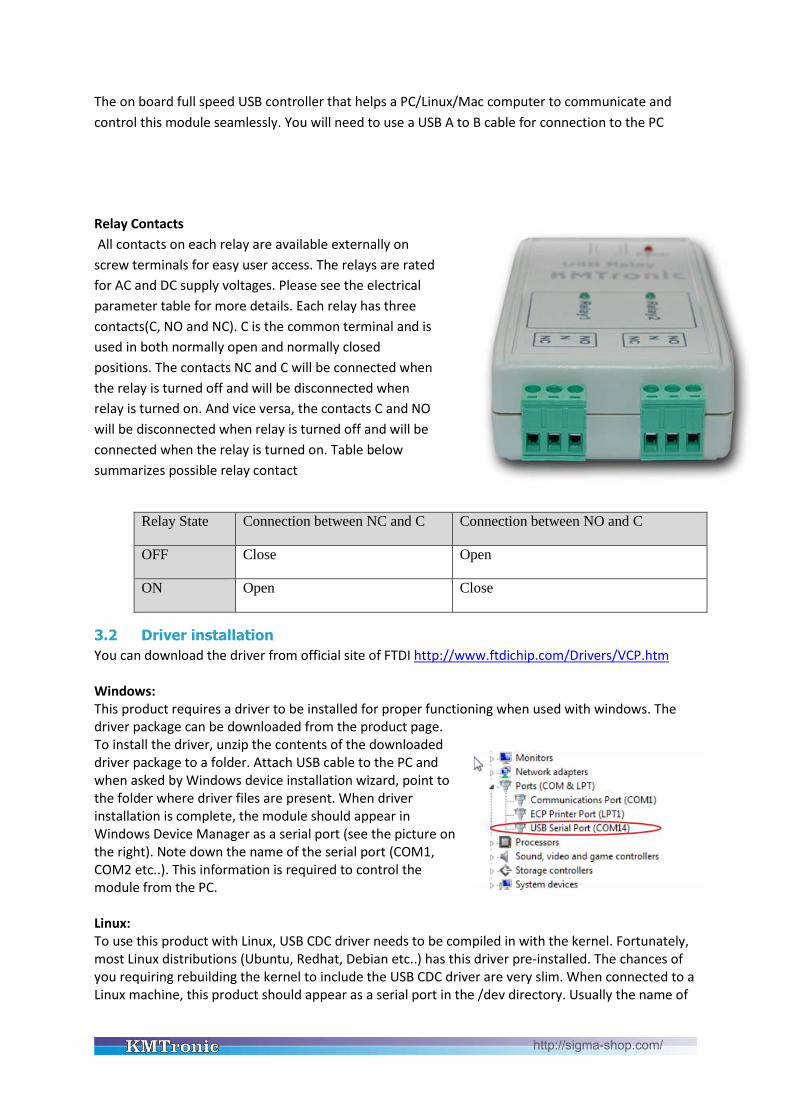
Relay Contacts
All contacts on each relay are available externally on
screw terminals for easy user access. The relays are rated
for AC and DC supply voltages. Please see the electrical
parameter table for more details. Each relay has three
contacts(C, NO and NC). C is the common terminal and is
used in both normally open and normally closed
positions. The contacts NC and C will be connected when
the relay is turned off and will be disconnected when
relay is turned on. And vice versa, the contacts C and NO
will be disconnected when relay is turned off and will be
connected when the relay is turned on. Table below
summarizes possible relay contact
Relay State Connection between NC and C Connection between NO and C
OFF Close Open
ON Open Close
3.2 Driver installation
You can download the driver from official site of FTDI http://www.ftdichip.com/Drivers/VCP.htm
Windows: This product requires a driver to be installed for proper functioning when used with windows. The driver package can be downloaded from the product page. To install the driver, unzip the contents of the downloaded driver package to a folder. Attach USB cable to the PC and when asked by Windows device installation wizard, point to the folder where driver files are present. When driver installation is complete, the module should appear in Windows Device Manager as a serial port (see the picture on the right). Note down the name of the serial port (COM1, COM2 etc..). This information is required to control the module from the PC. Linux: To use this product with Linux, USB CDC driver needs to be compiled in with the kernel. Fortunately, most Linux distributions (Ubuntu, Redhat, Debian etc..) has this driver pre-installed. The chances of you requiring rebuilding the kernel to include the USB CDC driver are very slim. When connected to a Linux machine, this product should appear as a serial port in the /dev directory. Usually the name of

the device will be “ttyUSBx” or similar. The name may be different depending on the Linux distribution you have. Mac: Similar to Linux, Mac operating system comes with the required drivers pre-installed. When connected to a Mac computer, the device should appear as a serial port.
3.3 Run our test program
You can download the program from: KMTronic_USB_Timer
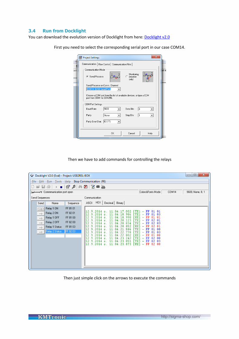
3.4 Run from Docklight
You can download the evolution version of Docklight from here: Docklight v2.0
First you need to select the corresponding serial port in our case COM14.
Then we have to add commands for controlling the relays
Then just simple click on the arrows to execute the commands

3.5 List of command set
No. Command Format Description
1 FF 01 01
FF 02 01
HEX Turn ON relay 1
Turn ON relay 2
2 FF 01 00
FF 02 00
HEX Turn OFF relay 1
Turn OFF relay 2
3 FF 01 03
FF 02 03
HEX Read the status of relay 1
Will return:
FF 01 01 if relay is ON
FF 01 00 if relay is OFF
Read the status of relay 2
Will return:
FF 02 01 if relay is ON
FF 02 00 if relay is OFF
4 Additional information
4.1 Handle inductive loads
General-purpose relays are typically designed to drive resistive loads, not inductive loads.
This is why electromechanical life ratings are published for resistive loads and not inductive loads. Inductive loads can best be defined as anything with a magnetic coil, such as a motor, solenoid, or a transformer. The purpose of this capacitor is to absorb the high voltages generated by inductive loads. Unlike resistive loads, inductive loads love power, and they will do everything they can to hold on to it. The unpleasant result of this power hunger is inductive kickback, and it has a devastating effect on the contact life of most general-purpose relays. This is true of both ac and dc inductive loads, although the inductive kickback is far worse with dc loads due to the constant current characteristic of dc power. How bad is the kickback? A 24-Vdc solenoid with a current consumption as low as a quarter of an amp will create a negative inductive kickback of more than 300 V. Also the high voltage kickbacks can easily brake the USB communication and the only way to fix it to unplug and plug it again.
Adding a suspension capacitor could easily reduce the problems. It has to be installed as close as possible to the Relay Board.

DME Polyester Film Capacitors are suitable for this job with capacitance around 0.47uF – 0,68uF will be satisfied.
Choose larger voltage rating than your power supply.
Search it at digikey.com -
http://www.digikey.com/scripts/dksearch/dksus.dll?FV=ffec2aa9%2Cfff40002%2Cfff80010%2Ce340003&k=Polyester+Film+Capacitor&vendor=0&mnonly=0&newproducts=0&ptm=0&fid=0&quantity=0&PV13=46&PV13=47&PV13=49
If you can't find it you can use other Metalized Polyester Film Capacitor.
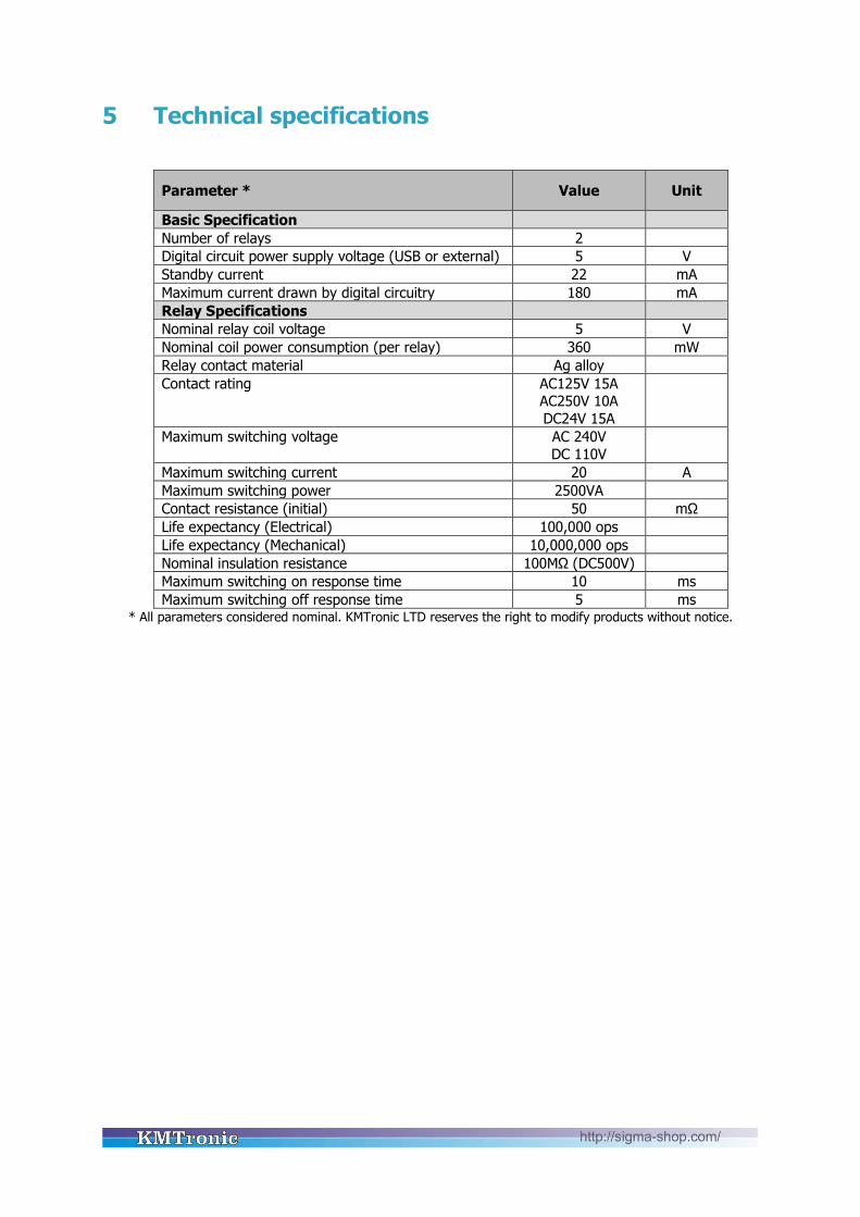
5 Technical specifications
Parameter * Value Unit
Basic Specification
Number of relays 2
Digital circuit power supply voltage (USB or external) 5 V
Standby current 22 mA
Maximum current drawn by digital circuitry 180 mA
Relay Specifications
Nominal relay coil voltage 5 V
Nominal coil power consumption (per relay) 360 mW
Relay contact material Ag alloy
Contact rating AC125V 15A AC250V 10A
DC24V 15A
Maximum switching voltage AC 240V
DC 110V
Maximum switching current 20 A
Maximum switching power 2500VA
Contact resistance (initial) 50 mΩ
Life expectancy (Electrical) 100,000 ops
Life expectancy (Mechanical) 10,000,000 ops
Nominal insulation resistance 100MΩ (DC500V)
Maximum switching on response time 10 ms
Maximum switching off response time 5 ms * All parameters considered nominal. KMTronic LTD reserves the right to modify products without notice.

6 Physical Dimensions
7 Sample code & Demo Applications You can find sample code and a demo application, as well as additional information and downloads
at:
http://info.kmtronic.com/
Manufacture By: KMTronic LTD
Bulgaria