relay logic student - universiti teknologi malaysiamohamed/ind automation notes/relay logic... ·...
TRANSCRIPT

ON/OFF CONTROL- RELAY LOGIC ON/OFF CONTROL ON/OFF control is a type of control which depends on discrete input signals to produce discrete output. Discrete signals are normally associated with binary numbers 1 or 0 (i.e. ON or OFF). INPUT SIGNAL LOGIC
INPUT ELEMENT (example: switches,
push buttons, sensors etc..)
ON/OFF
CONTROLLER
ACTUATORS (example:
solenoids, motors, light indicators,
alarms etc.)
input signal
output signal
I
O
N/O
TRUTH TABLE
I O
TRUTH TABLE
I O
I
O
N/C

ON/OFF CONTROL- RELAY LOGIC
TRUTH TABLE
I1 I2 O 0 0 1 0 0 1 1 1
O
I1
N/O
I2
N/O
I1 N/O
I2
O
N/O
TRUTH TABLE
I1 I2 O 0 0 1 0 0 1 1 1

ON/OFF CONTROL- RELAY LOGIC BASIC ELECTRO-PNEUMATICS Electro-pneumatics actuators are very popular and widely used in automated industries. Some basic electro-pneumatics arrangements are shown below.
single acting cylinder (spring return)
Y3/2-way single solenoid valve (spring return)
S
Y
24Vdc
0V
double acting cylinder
Y5/2-way single solenoid valve (spring return)
S
Y
24Vdc
0V

ON/OFF CONTROL- RELAY LOGIC RELAY : a relay is an electro-mechanical device which allows single input signal controlling multiple outputs.
N/O - normally open N/C - normally closed
double acting cylinder
Y1 5/2-way double solenoid valve
Y2
S1
Y1
24Vdc
0V
S2
Y2
24V/240V
0V
N/O N/C N/O N/C N/O N/C N/O N/C
Relay (R)
R1 R2 R3 R4

LOGIC CONTROL
ON/OFF control can be divided into two types:
i. ii.
LOGIC CONTROL In logic control the system output/s is controlled based on the pre-determined input logics. Example I A system consists of two indicator lights (L1 and L2) and an alarm. The system is controlled by a switch (S1). Initially indicator L2 is on. Build a control circuit as such when S1 switch is pressed indicator L1 will on, the alarm will trigger and indicator L2 will off.

LOGIC CONTROL Example II A system consists of three indicators (L1, L2 and L3), an alarm and a double-acting cylinder. The system is controlled by two switches (S1 and S2). Initially L3 is on. Build a control circuit as such when S1 is pressed L1 will on, the alarm will trigger and the cylinder extends. If S2 is pressed L2 will on, L3 will off, the alarm will trigger and the cylinder retracts.
Y1 Y2

LOGIC CONTROL Exercise I A system consists of three indicator lights (L1, L2 and L3), an alarm, two double-acting cylinders, and one single acting cylinder (refer to the Figure below). The system is controlled by four switches namely S1, S2, S3 and S4. Initially indicator L3 is on. Build a relay logic control circuit based on the following conditions:
If S1 is pressed L1 will on, cylinder A and cylinder B extends Cylinder A will only retracts if S2 is pressed Cylinder B will only retracts if both S2 and S4 is pressed Light L2 will on to indicates either cylinder A or cylinder B has been retracted Cylinder C will extend if S1 is pressed together with S3 or S4. If cylinder C extends L3 should go off and the alarm should trigger.
Y1 Y2 Y3 Y4 Y5
Cylinder A Cylinder B Cylinder C

LOGIC CONTROL Exercise I (ANSWER)

SELF-HOLDING CIRCUIT: CONTINUOUS START- STOP BUTTON - in the previous examples, all operations are directly controlled by the input signals. However, it is normal to have two
switches to control an operation of a system. One switch is used to start the system meanwhile the other is used to switch off the system.
- the circuit shown below can be used to let a system operates continuously until a stop switch (STOP) is pressed. - such circuit is known as self-holding circuit

SELF-HOLDING CIRCUIT: CONTINUOUS START- STOP BUTTON Example III Build a control circuit such that the pneumatic cylinder shown below operates continuously when the START button is pressed and stops when the STOP button is pressed.
Y1 Y2
a0 a1
a0 and a1 are limit switch

SELF-HOLDING CIRCUIT: SINGLE SOLENOID VALVE - the self –holding circuit is also required when a single solenoid (spring return) valve is used. Example IV Build a circuit which can operates a cylinder in and out continuously when the START button is pressed. The cylinder is controlled using a single solenoid valve and will only stops its operation when the STOP button is pressed.
Y1
a0 a1

SENSORS - there is a lot type of sensors. Sensor which does not need power supply has two wires and operates similar to
switches or contacts. - Sensor which need power supply has three wires. Two of the wires which are normally red/brown (+ve) and blue (-
ve) are connected to the power supply which is needed by the sensor circuitry. The third wire (which is normally black colour) provides the sensor’s high/low signal. The Figure below shows how three-wire sensors can be connected to replace the limit switches for the control circuit in Example III.

TIMER: DELAY ON - timer is a device which can be used to control a system operation within a certain preset time. There are two types of
timer; delay ON and delay OFF. Delay ON timer: when triggering rung goes on, the timer delays the output from switching on until the preset delay has
been timed out.
Example V : Delay ON
device symbol : contact symbol:
S1
0V
5sec
t1
11t 2
1t
24Vdc

TIMER: DELAY OFF Delay Off timer: when the triggering rung goes true, the timer immediately turns the output on, and doesn't turn the output
off until the preset delay has timed out.
Example VI : Delay OFF
S1
0V
5sec
t1
11t
21t
24Vdc I
0
I
0
I
0
5 sec
switch S1
alarm
light
device symbol : contact symbol :

COUNTER There are two basic counter types: count-up and count-down. When the input to a count-up counter goes true the accumulator value will increase by 1 (no matter how long the input is true.) If the accumulator value reaches the preset value of the counter, the output will be set. A count-down counter will decrease the accumulator value until the preset value is reached.
Example VII : Count UP counter
device symbol : contact symbol :
S1
0V
10
C1
11C 2
1C
24Vdc
0V
RESET
count up
count down

TIMER & COUNTER EXERCISES Exercise I Repeat Example III. Instead the cylinder operates continuously, it stops after 20 seconds Exercise II Repeat Example III but the system stops after 20 strokes.

SEQUENCE CONTROL Sequence control is used to control the operation of a system which has a series of sequence to be followed. There are several design techniques or methods which can be used to provide a sequence control to a sequential operation. One of the most popular techniques is the Shift Register technique. In this technique each operation output/s is control by an individual power line. The power lines are arranged according to the sequence of the system operation. All the power lines has to be linked to form a sequence controller. A general form of the power line is shown below.

SQUENCE CONTROL EXAMPLE Example I A system consists of two cylinders A and B has a series of sequence shown below. Build a control circuit for the system.
SYSTEM SQUENCE STEP 1 When the START switch is pressed and a0 is ON then cylinder extend A STEP 2 When a1 is ON extend cylinder B STEP 3 When b1 is ON retract cylinder B STEP 4 When b0 is ON retract cylinder A
Y1 Y2
a0 a1
a0 and a1 are limit switches Y3 Y4
b0 b1
b0 and b1 are limit switches
CYLINDER A CYLINDER B

SQUENCE CONTROL EXAMPLE
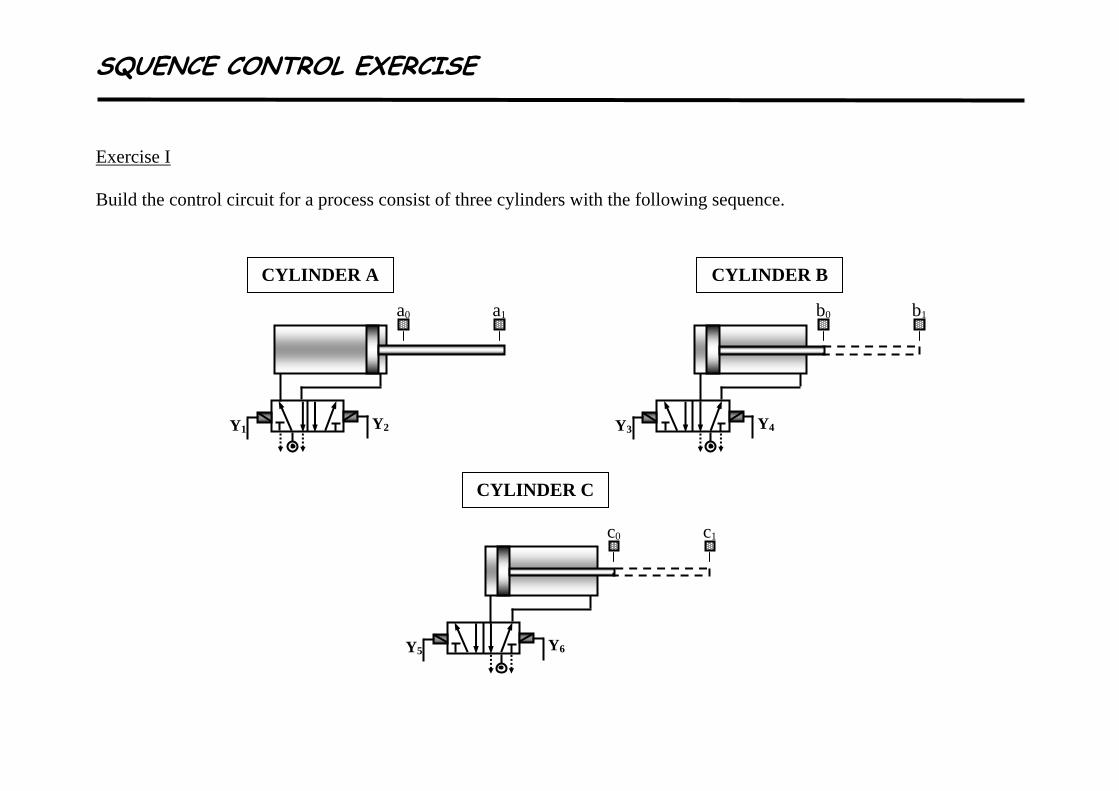
SQUENCE CONTROL EXERCISE Exercise I Build the control circuit for a process consist of three cylinders with the following sequence.
Y1 Y2
a0 a1
Y3 Y4
b0 b1
Y5 Y6
c0 c1
CYLINDER A CYLINDER B
CYLINDER C

SQUENCE CONTROL EXERCISE
PROCESS SQUENCE STEP 1 When the START switch is pressed and c0 is ON retract cylinder A STEP 2 When a0 is ON extend cylinder B STEP 3 When b1 is ON retract cylinder B ** REPEAT STEP 2 AND STEP 3 FOR 20 COUNTS ** STEP 4 When b0 is ON extend cylinder A
STEP 5 When a1 is ON extend cylinder C
STEP 6 When c1 is ON and approximately 30 seconds has elapsed retract cylinder C ** THE PROCESS CONTINUES UNTIL THE STOP SWITCH IS PRESSED **