reliability and voltage stability test system - home - … … · · 2015-09-21reliability and...
TRANSCRIPT
Reliability and Voltage Stability Test System
Leonardo Lima
Kestrel Power Engineering
1

Single Line Diagram
• 75 buses, 32 generators
• 3200 MW (generation)
• 230 kV (black) and 138 kV (blue)
2

System Characteristics
• Based on the 1979 IEEE Reliability Test System
• Added explicit representation of generator step-up transformers
• Moved loads to MV buses with step-down transformers with on-load tap changers (power flow and dynamics)
• This is a test system: system configuration and dispatch is not N-1 secure

Additional Features
• Slow voltage collapse phenomena
– Transformer automatic on-load tap changers
– Generator over-excitation limiter
– Load characteristics recovering from voltage-dependent models (usual representation for dynamics) to constant power (usual representation for power flow)
Additional Features
• Fast voltage collapse phenomena
– Fraction of total load represented by induction motor model
– Application of SVC

Critical Contingency
• 138 kV underground cable (106 to 110)
– 250 MVAr of total charging
– 75 MVAr reactor at each terminal
– Line-connected shunt reactors
R X
2
B
2
B
cable represented by -model
breakerBus
106
Bus
110
Line-connected
reactor

PV and QV Curves
0 MVAr

PV and QV Curves
• Base case (N-0) in red
• Two non-critical contingencies
• No power flow solution for critical contingencies

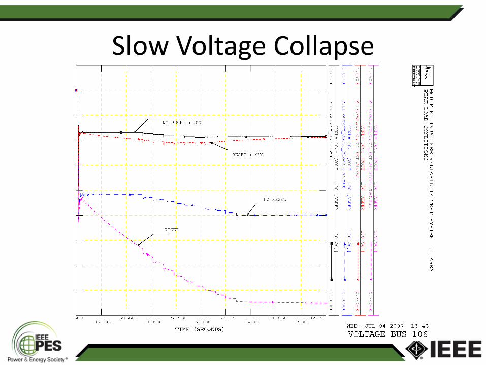
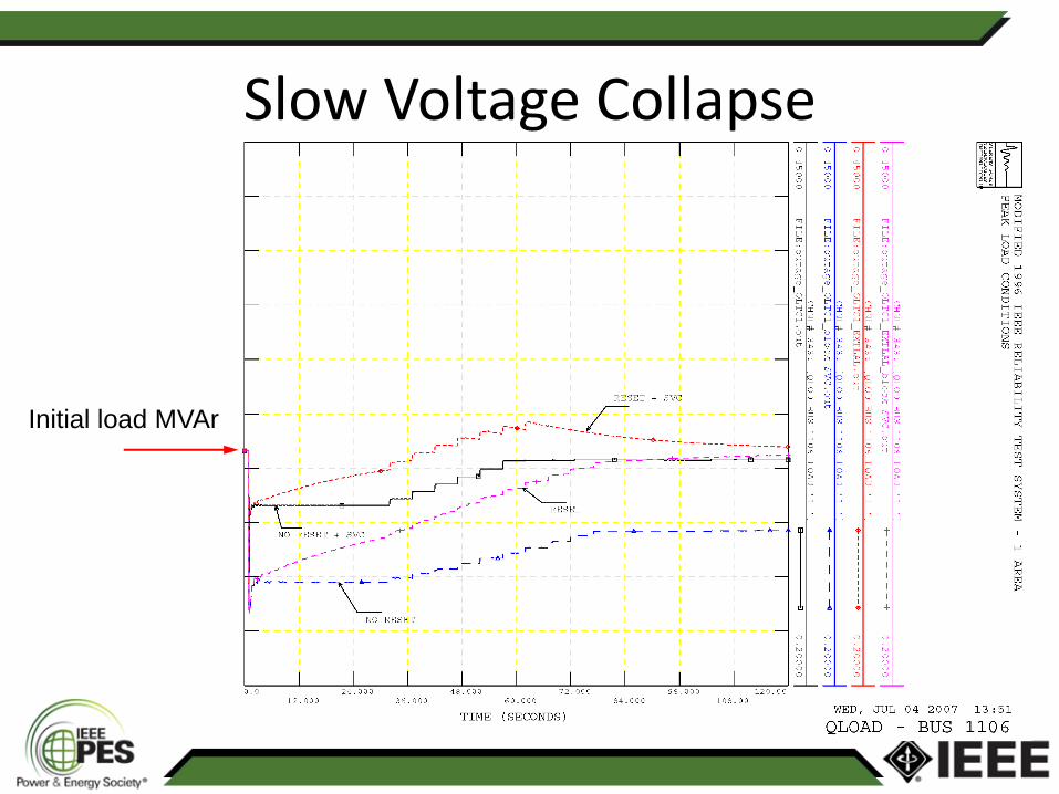
Slow Voltage Collapse
• Critical outage
– Trip cable (and line-connected reactors)
– No fault
• Simulations
– With automatic OLTC, without load recovery
– With automatic OLTC, with load recovery
– With SVC, without load recovery
– With SVC, with load recovery
Slow Voltage Collapse

Slow Voltage Collapse
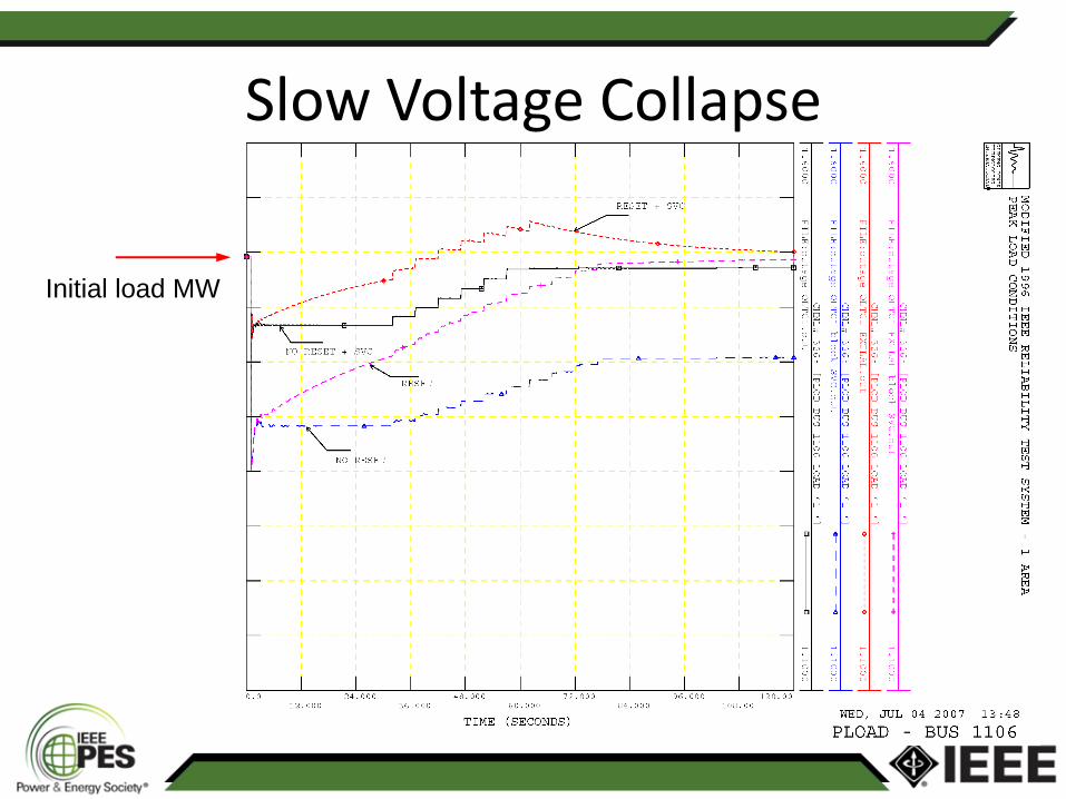
Slow Voltage Collapse
Initial load MW
Slow Voltage Collapse
Initial load MVAr
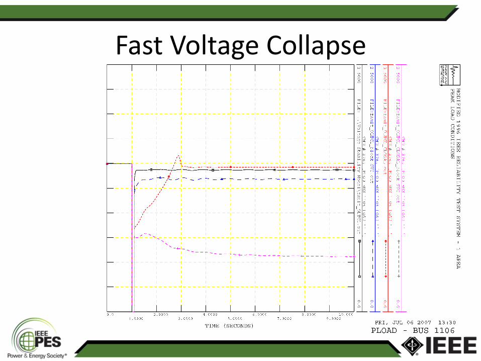
Fast Voltage Collapse
• Modeling a fraction of the total load as induction motors
• Three-phase fault at bus 106
• Total clearing time = 6 cycles
• Trip cable 106-110

Fast Voltage Collapse

Fast Voltage Collapse
Fast Voltage Collapse

Fast Voltage Collapse

System Data
• PSS/E format
• DSA Tools format
Specific Models
• Generators
– GENSAL (5th order model, salient pole machines)
– GENROU (6th order model, round rotor machines)
• Excitation Systems
– IEEET1 (IEEE Std. 421.5 DC1A)
– EXAC1 (IEEE Std. 421.5 AC1A)
– SCRX (simplified IEEE Std. 421.5 ST1A)
Specific Models
• Power System Stabilizers
– IEEE Std. 421.5 PSS2B
• Over-Excitation Limiter
– MAXEX2 (summation point OEL)
• Turbine/Speed Governors
– IEEEG1 (steam turbines)
– HYGOV (hydro turbines)
Specific Models
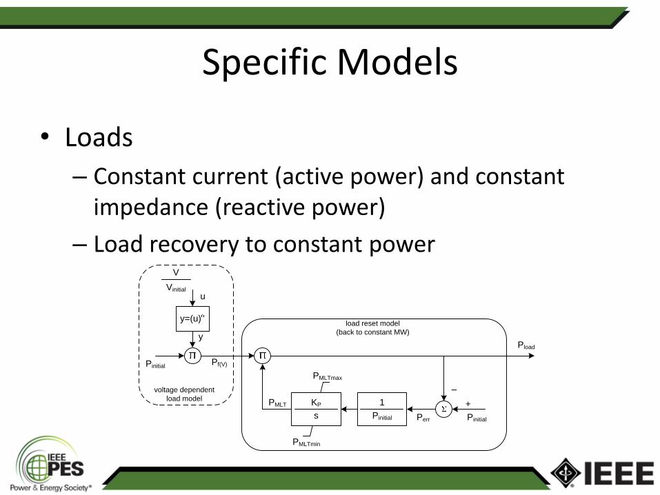
• Loads
– Constant current (active power) and constant impedance (reactive power)
– Load recovery to constant power
PMLTmax
PMLTmin
KP
s
1
Pinitial
PMLT
Pinitial
–
+
Pinitial
y=(u)
y
uVinitial
V
Pf(V)
voltage dependent
load model
Perr
Pload
load reset model
(back to constant MW)
Specific Models
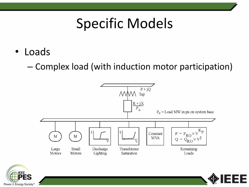
• Loads
– Complex load (with induction motor participation)
Specific Models
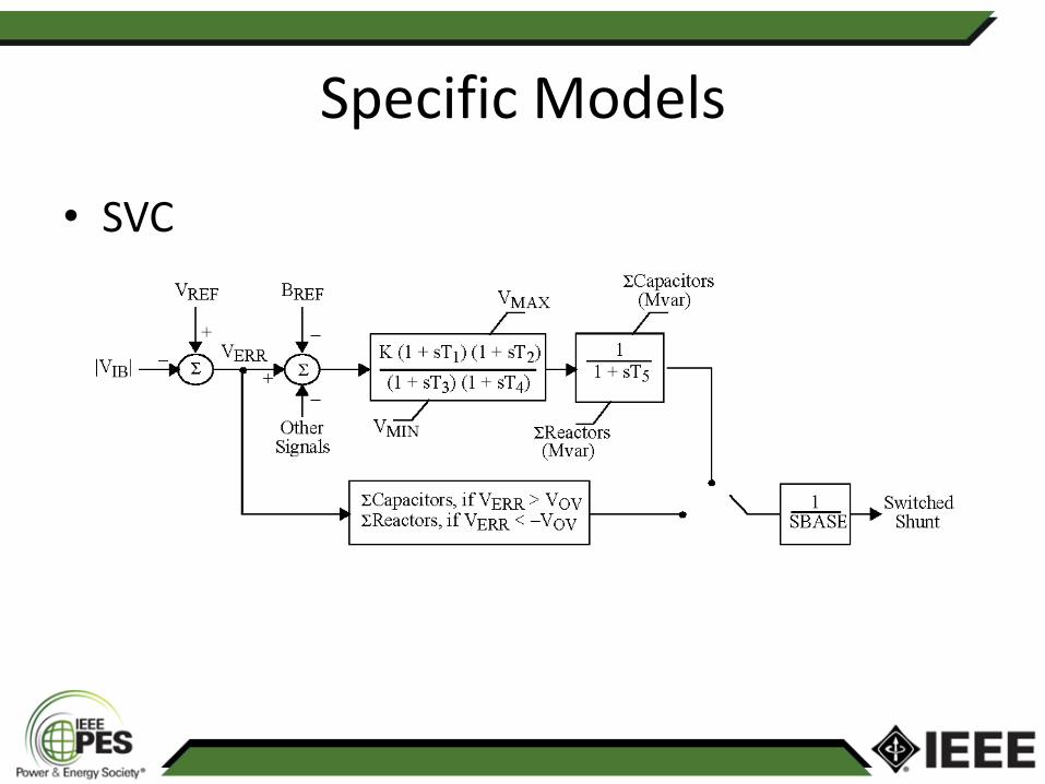
• SVC