reliability assesment and condition …yousefim/bfiles/shovel fault... · web viewkey words:...
TRANSCRIPT
RELIABILITY ASSESMENT AND CONDITION MONITORING OF A SHOVEL TEST BED
Rahman Yousefi Moghaddam and Michael G. Lipsett
Department of Mechanical Engineering, University of Alberta, Edmonton, Canada .
Excavation requires a high amount of interaction between the machine and the environment. Uncontrolled interactions can cause impacts and other high-load conditions that negatively affect operational performance and cause damage to the machine. Although such mechanical systems are controllable under specified control parameters for firm ground conditions, the dynamics of a shovel on an elastic foundation makes it prone to oscillation. On soft ground conditions such as oil sand, deformation of the ground under the tracks exacerbates the effect. High-bandwidth inputs can come from shock loading within the machine, such as in loose joints and poorly tuned motor controllers, or from the dynamics of the working environment, including fast contact of the bucket in hard digging conditions.
Reliability of a machine hydraulic shovel is classically studied based on monitoring the machine in a certain period of operating time while it’s doing the different tasks; but an excavator performs different tasks, which do not necessarily have the same hazard rate.
, while these operations are not necessarily following the same failure rate.
In this work we recognize the variable failure rate as an important factor which should be to considered in evaluatingon of reliability, and. In return we investigate the point of machine-environment interactionstage where the system has the highest hazard rate among all machine operations, compareding to the other basic operations. In this regard, aA laboratory setup has been developed to investigate the dynamic effects of well-defined faults and ground-tool interactions on the reliability of a simplified mechanism representing shovel digging shovels, using a simplified dynamics model. Reliability of the test rig has been will be assessed following a the classical system reliability approachanalysis; h. However, a more detailed study has been done takes place on the soil-tool interaction stage, in order to come up withto develop methods ways to recognize athe fault that might occur during machine operation. This fault recognition allows for enables us to modification of y the plant and machine controller mode in order to achieve an acceptable level of performance with a lower hazard rate on a specific and component, thereby making the machinea more reliable. Numerical experimental results are presented for working condition. Applying an idealized laboratory-scale model that includes a time-varying load to represent soil-machine interaction and controlled a model of a crack in one machine element, showing the effect of a crack such fault on the overall powerenergy utilizationrequirement of the system will be studied.
Key Words: Hydraulic Shovel, Reliability, Fault Monitoring
1 INTRODUCTION
The hHydraulic shovel has a long history ais athe primary loading machinetool in most mines and construction. Being the key products in all types of construction and building applications makes this machinery one of the most important equipments in such industries.
<MGL: I suggest we remove this next paragraph, because we do not consider human interactions in this work. That’s another paper…>
In 1898 Frederick W. Taylor performed studies to determine the most appropriate designs for shovels [1] . I, it was not until 1958 thatwhen Williams [2] recognized that human-element reliability must be included for a realistic in the overall system-reliability prediction; otherwise, such a prediction would not be realistic. In 1960, the work of Shapero et al. [2] further

stressed the importance of human reliability in engineering systems by pointing out that human error is the cause for 20 to 50% of all equipment failures.
Aside from the Human-Machine interaction and its role in the reliability of the Shovels, tDhe reliability of the system itself can be an interesting research area. Due to the fact that Hydraulic excavators and shovel are highly used in the construction and mining, the downtime of these machines can bewould be very costly. A comprehensive study by Edwards et al. presents a method on predicting the downtime costs of shovels in mining industry [21]; . gGreater downtime leads to loweress utilization of the machine, which consequently influences the total excavation cost. In studying mining technology, it is most convenient to applyTypically the term "reliability" is used to characterize the probability of satisfactorycorrect performance operation of the equipment for an interval of time. Although the research in this area is very promising, only a limited number of studies attacked the main problem directly. De [32] discussed the reliability assessment technique of a hydraulic excavator, based on the acquired data taken from an open- cast mine during its useful life. Majumdar [43] investigated failure of hydraulic excavator system in different environments to estimate the proper modeling of its reliability and applied FMEA to identify high risk prone failure modes. Samantha et al. [54,65] did a series of work to analyze the reliability of shovels based on the reliability of the subsystems. Hall [76] characterized the operation of a heavy hydraulic excavator and described the chronic and acute failure modes of the machine.
TIn the first section part of this work we will studyconsiders a systemthe real model of a hydraulic shovel, describing the components and the entire system, modes of failure, and its reliability assessment by aas the classical systems reliability approach. WiWe point out the fact ththin different operating modes, at the reliability of the system does not have the same failure rate, and so accordingly sucha single reliability assessments would not serve in favour ofprovide a realistic evaluation of reliability, unless the weighted average but would be an average of different reliability factors were modeledtasks.
Describing basic machine operations, we investigate the stage of machine-environment interaction, where it has the highest hazard rate, and consequently requires more attention.
Acquiring the real time data from a full- scale machineodel is generally very difficult, and so . Hence a test rig has been developed that represents athe simplified model of the hydraulic shovel digging dynamicsis designed. Certain physical faults can bewould be introduced to its components to and characterize its failure modes, with the objective of would be characterized. It is desired to capturinge the effects of these faults and possibly associatinge the variation in consumed energy with those faults. Such a connection might lead to a kind of constitutive relationship between the fault and energy dissipation in the damaged element over time, and thus a predictive model enabling us to monitor the condition of the system and characteristic of possibleof damage. Consequently the understanding of the dynamics of damage accumulation can be used to implement we will be able to engage properan appropriate control scheme mode to deliver satisfactory system performance without handle the situation and avoid furthering the damage.
2 HYDRAULIC SHOVELS
There are many different types of earthmoving equipments that usehave a bucket to dig into the ground, generally classed as with the general name of excavators; h. However, they can be classified into different categories according to the size, configuration, and the actuation method. Hydraulic excavators are a class of machines that use hydraulic cylinders as a mean of actuation and can come in two types: backhoe excavators (where the bucket, stick and boom system has the ground-engaging tool pointing toward the machine body)are attached to the rear side of loader or tractor) and shovels (where bucket pointsis toward the working face). Each This variation in the configuration has different manipulability and loading capacity. gives different capabilities of the two systems. Large front and heavy s shovels are mostly used in mining, while smaller shovelsones are used in construction industry.
2.1 Machine Components
Figure 1 showsdescribes the components of a heavy hydraulic shovel. The cCarriage includes major components of the excavator: the engine, fuel, hydraulic pumps, and supporting structure for the shovel attachmentdigging arm and the operator cabin. The shovel attachment comprises a boom, stick, and bucket. The bBoom is thea link of excavation arm connected and directly to the carriage through a revolute joint. Its main function is to raise and lower stick and bucket complex through
actuation of the boom hydraulics. Distal to the boom is Next to it is the stick, which is the second component of the linkage. The sStick also pivots through a revolute joint and attached to the end of the boomboom.
2
Hydraulic Actuators
Bucket
Stick
Boom Carriage
Power Units
Tracking System
Figure 1 – Full model of a Hydraulic Shovel Schematic

The bBucket is, considered to be the end effector of the system and is used to dig into the ground and carry the charge of excavated material. There are also three separately commanded hydraulic cylinders that are used to actuate each of the three links (b: Boom, sStick and bBucket. Power units and hydraulic pumps and electrical components are all locatedplaced in the carriage. The carriage and shovel attachment comprise entire above mentioned components form the upper body of the shovel, which and can rotates aboutround a vertical axis through a mechanical drive system. The lLower body is in charge of
movingmoves the machine on tracks driven by system and mainly is the other name for the tracking system which is a part of the propel system.
2.2 Basic machine operations
The basic mining machine operating cycle, shown in figure 2, consists of a digging pass through the bank or material, a loaded swinging with the load (or carry) to the dump position, the dumping (usually into a haul truck), swinging empty swing back to the digging face, and repositioning or spotting of the bucket at the face [76]. The hydraulic flow rate of each actuator at the boom, stick, and bucket is controlled and hence the speeds of those systems are also maintainable. Vertical and horizontal motion of the bucket are dictated by actuating the boom and stick cylinders, which draws the motion of the bucket
through the working space, while bucket cylinder controls the orientation of bucket in order to facilitate its motion through the bank, so that the machine has a good angle of attack to penetrate the soil, and does not spill material whilst swinging.
Since a sShovel has to penetrate (dig) and then separate (lift) the dog soil, two important parameters must to be taken into consideration, shown in . Figure 3 shows them as “crowd force” and the “breakout force,” withand both forces acting at the tip of the shovel’s bucket tooth line teeth [87]. The mMachine itself can also move about the pit and position the excavator at the digging face, either on wheels or tracked crawlers, so aswhich also has to be stable enough to support the machine’s weight and react to digging forces. This positioning is an
essential component to facilitate manoeuvres and minimize damage from material sliding down the face.
According to this brief review, tThere are different sources of damage that can occur during the machine operation. EBasically, evaluation of potential damage to such a dynamic systems is based on the average behaviour of the system - overin a certain time domain - which might vary over time time to time due to the changes in the working situation and operational requirements. This would consequently cause a change in the system's hazard rate.
(1)
where is time dependent failure rate, and are parameters of failure rate function. This log-linear failure rate function represents the possibility of error occurrence due to the structural weaknesses.
<MGL It would be good to express this mathematically.>
Spotting the bucket might be riskier at certain times due to physical constraints, and digging trajectorystyle might vary upon to different environmental conditions that affect soil strength. Such changes in operating conditions This can change the related hazard rate for each of these activitiesoperations during a set of tasks in within the dutya cycle. AHowever a comprehensive look at a shovel's duty cycle (Spotting, digging, swing, dumping and return) revealshelps us to recognize digging as the harshest part of operation, with high structural loads, as well as variability in since there is a major source of uncertainty within the interaction period, forces between bucket and ground. Variation of soil parameters affects the amount of force the machine must produce during digging - would face and the kind of damage the machine it might experience. H, hence a static hazard rate time distribution for this sort of damage during digging is likely inappropriatedoes not fit. Damage associated with other aspects of shovel However the remained operations and the associated damages can still be characterized on an average basies.
3
Shovel's Cycle
Swing
Dump
Return Swing Bucket Spot
Dig
Figure 2 - Shovel'ss Duty CycleSwing
Hydraulic Actuators
Bucket
Stick
Boom Carriage
Power Units
Tracking System
Figure 1 – Full model of a Hydraulic Shovel Schematic

DIn many cases downtimeDowntime from unreliable operation is substantial and can greatly affect productivity and should be considered in every decision before setting long- term fleet replacement programs and optimum changeover timeframes.
The associated costs of downtime can include the associated cost of the machine, the cost associated withof idle skilled operator, inconvenience costs, and cost associated with idle capital investment. <This needs to be explained in more detal, or leave it out.>
Comprehensive assessments of machineplan (or plant)t downtime enables informed decisions to be made on optimum replacement times for plant when developing long term plant replacement programs. It is then very important to detect a fault earlyat first place, identify it and respond properly to minimize costs ofthe damage and lost production. This can also be supported by selecting an
appropriate control mode for the type of operation to reduce costs of damage while the machine is still operating.
2.3 Reliability of Shovels
In the study of the reliability of hydraulic shovels, different approaches have been taken depending on the available data and initial assumptions in order to achieve a more realistic reliability estimate.
Considering the For the mMajormajor systems and components of a hydraulic shovel described in previous sections, . It is helpful to know the importance of each component affects nd how they are related to form the overall system performance and reliability. One classical approach is to identify the reliability of each component in order to build a bottom-up estimate of the reliability of the system. As there is no redundancy in a shovel attachment, the failure of even one link in the hydraulic shovel system leads to breakdown of the whole system; and so in calculating the reliability we need to pay attention to failure of the first link, independently of whether the remaining links are working [32]. The hydraulic excavator consists of a series of electro-mechanical units such as Power unit, Pump unit and Utilization unit. These units each also consist of several components (each with different reliabilities); but the reliability of the whole system is found from the combination of the reliabilities of the components. The reliability assessed for the useful life period of the equipment subject to the combination of the chance failure and wear out failure that is modeled by:
(2)
where chance failure is described by an exponential distribution ( is the chance failure rate). Wear out is described as fraction applying a normal distribution
(3)
where T is component age, is mean wear out life and is standard deviation from . When the components are combined in series, the reliability of the system, is the product of all component reliabilities in the period (t).
, . (4)
Another approach considers the system to be a repairablerepairable. In the probabilistic approach, stochastic point process is applied to model the repairable system's failure occurrence, considering the fact that the time of the system's repair is negligibly small compared to its time to failure [8]. Comparing this approach to a statistical one, the main idea here is to characterize the failure of the excavator system by a stochastic point process rather than by a component-related distribution function as applied to time of failure of parts or components. Majumdar [3] It is claimed that the best results are obtained using a failure rate that is independent of the environment type and can adequately modelled by Homogenous PPoisson PProcess (HPP) with constant failure rate estimated by:
(5)
4
Figure 3 - Bucket - Ground interaction: Break out (left) and Crowd (right) forces (reprint from [87])

where n is the number of failures observed for an excavator and the time to the nth failure. For an HPP model, the reliability
function in any time interval of for the excavator system is given by:
. (6)
Fault tree analysis is also regarded as an effective means of assessing the reliability of the complex system. Mosinets [9] mentioned that the probability of correct operation of a cyclic excavator corresponds to specific loading power consumption below 1.0 , while the probability of correct operation of a continuous-acting excavator corresponds to power consumption below 0.5 . These relative rates of expenditure of electrical energy are independent of the type of excavator, and correspond only to the state of the solid rock, on the working of which the differential characteristic of energy expenditure rises sharply within certain limits. <explain why this occurs.>
In the study of the reliability of hydraulic shovels, different approaches have been takenutilized, depending on the availableprovided data and initial assumptions. Some of these approaches are similarare in parallel to each other and are only slightly different. Examples are statistical approach, probabilistic approach, and fault tree analysis. <How are these different? Reference?> Fault-tree analysis mayIt can be used in the evaluation of the reliability of a hydraulic shovel or alternative design,s and to identifyies critical components for the success of such system and potential causes of system failure. The first step is to produce the minimal cut set list for each system top event. A minimum path set is the collection of the smallest component sets that are required to work in order to keep the system working. A minimum cut set is the collection of the smallest component sets that are required to fail in order for the system to fail [9]. Developing a reliability block diagram and fault tree of the shovel system, then the minimum cut sets and the minimum path sets can be obtained from the fault tree, which leads to identification of the reliability of the machine and its sub-systems. The reliability is equal to the probability that at least one of the minimal path sets works, while the unreliability of the system is equal to the probability that at least one minimal cut set is failed. <explain what cut sets and path sets are and give a reference>
Since the focus of this work However in this work we're focusing onis the digging taskperiod, where the interaction of machine/environment varies and the digging force can be several times higher than nominal, the . Thus variation of damage rate is higher than for systems operating with little variability in load.and requires more attention. The high variability of loads is demands a cautious monitoring of the system inputs and outputs, in order to monitor changes (damage) within the system, its progress (since damage effects generally increase with time), and how this affects the energy requirements of the system. For example, a damaged bearing will produce heat, which dissipates energy that could otherwise be covnverted to useful work.
3 SHOVEL TEST RIG
In order to investigate the effect of ground condition such as looseness and some other faults in the shovel system, a shovel test rig has been developed. In this regard, some of the duties of the hydraulic shovels are ignored. The main part of the excavation task – which is to dig the ground – is modeled using a slider-crank mechanism, but other capability of a hydraulic shovel is not modeled. – will be practiced. It is planned to utilize the test rig with data acquisition set and control unit in order to study the dynamic behaviour of the system under different conditions. A complete cycle is to have a full turn of the crank resulting in a single reciprocation of the slider. When the slider moves forward, it would engages with the soil and does a single dig, with data such as forces, pressures and deflections acquired in this period. The test rig will be operated under computer control to study the dynamic behaviour of the system under different conditions, including digging soils and operating with faulty components.
3.1 Models and Components
The sShovel test rig consists of four parts as shown in the photograph it appears inin figure (4): Power Unit: i Including an inductionthe electro motor and variable frequency drive (VFD);. Transmission: with gGear box, shafts and joints;. Utilization Unit: comprising a slider-crankCrank- slider M mechanism and bBlade; and . Control Unit: with a computer cController and
input sensors for measuring state variables of machine dynamics and machine condition indicators. The eElectrico motor has to provide enough power for the system to dig into the soil. A control signal commands the VFD, which provides the required torque at the nd
5
Figure 4 - Shovel testbed and its components

voltage offor the electricor motor. Power is transmitted through a spur-gear box connected to the crank through a coupling and a flange. Rotational motion of the crank is then converted to the translational motion of the slider through a connecting rod. The connectingCon- rod is connected to the cCrank and the sSlider through journal bearings. The sShovel blade, representing the bucket, is mounted to the slider (and so the two are considered to be one single part). Since the vertically oriented blade hais only having horizontal motion, this mechanism it's only models only ing the crowd force of athe bucket (according to figure 3).
In order to achieve the control action, a data acquisition system is required (in terms of transducers and sensors) to provide data to a controller in a timely manner, which in turn drives actuators to modify the system dynamics. In other words to haveTo achieve the required performance, both the controller and plant (the machine with its mechanical setup (pPower unit, tTransmission unit and uUtilization unit) mustshould be functioning.
Figure (5) shows one of the possible models for soil tool interaction, the coulomb model, in which parameters are: α the measured Tool tool Angleangle, β the soil Surface surface Angleangle, H the depth of Penetrationpenetration, ‘γ’ the unit Weight weight of the Soil soil (500 kg/m3 < γ < 3000 kg/m3), δ the soil-Tool tool Friction friction angle (10º < δ <40º), and ‘Φ’ the s‘oil-Soil soil Internal internal Friction friction Angle’ angle (10º< Φ<50º)), and c ‘Soil Cohesion’ (0< C<30). Applied force on the blade can be estimated as the differencesubtract of passive and active forces on the two sidesd of the blade [10]:
(17)
Assessing <where is C in this equation?>
Reliability
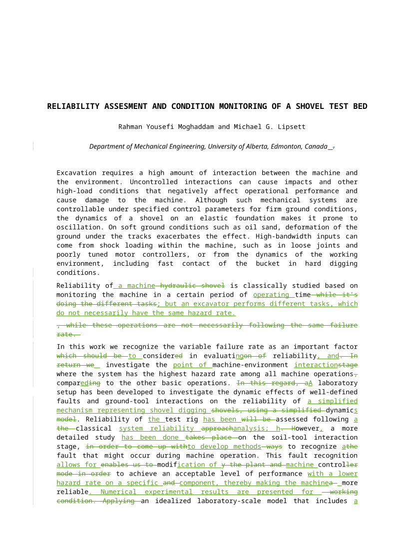
The proposed reliability block diagram (RBD) of the shovel rig is shown in figure (6), where it is divided into a control unit and a mechanical unit - which itself is divided into three subsystems P, T and U, with individual reliabilities as. shown in Table 1. This RBD can be used to find the fault tree as it is presented in figure (7). Tables should be presented in the form shown in Table 1.
Figure 6 - Reliability Block Diagram for the Shovel Rig (Power, transmission, utilization and control units)
VFDElectro motor
Gear box Coupling
sBearings Con-rod Slider Blade
PU
TU
UU
Controller Sensors
6
Table 1
Components of the Shovel rig and their reliabilities
Component VFD Electro motor
Gear box Coupling Bearings Con-rod Slider Blade Controller
Sensors
Reliability R1 R2 R3 R4 R5 R6 R7 R8 R9 R10
Figure 5 - Soil-Tool Interaction during a dig

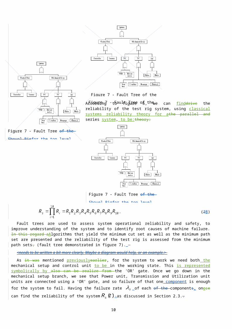
Figure 7 - Fault Tree of the Shovel Rig
Figure 7 - Fault Tree of the Shovel Rigfor
the top level failure of the Shovel test rig
Figure 7 - Fault Tree of the Shovel Rigfor
the top level failure of the Shovel test rig
Figure 7 - Fault Tree of the Shovel Rig
According to figure 6, we can finddrive the reliability of the test rig system, using classical systems reliability theory for athe parallel and series system, to be:theory:
. (28)
Fault trees are used to assess system operational reliability and safety, to improve understanding of the system and to identify root causes of machine failure. In this regard aAlgorithms that yield the minimum cut set as well as the minimum path set are presented and the reliability of the test rig is assessed from the minimum path sets, (fault tree demonstrated in figure 7).
<needs to be written a bit more clearly. Maybe a diagram would help, or an example.>
As it was mentioned previouslyearlier, for the system to work we need both the mechanical setup and control unit to be in the working state. This is represented symbolically by also can be realize from the ‘OR’ gate. Once we go down in the mechanical setup branch, we see that Power unit, Transmission and Utilization unit units are connected using a ‘OR’ gate, and so failure of that one component is enough for the system to fail. Having the failure rate of each of the components, onece can find the reliability of the system -as discussed in Section 2.3..
4 FAULT AND CONDITION MONITORING
As it is mentioned earlier, cChanges in the dynamics of the system will ould varyaffect the system response for the same inputs. These changes might come either from the environment or from the physical system. We discuss tThese two typetypes of changes can be considered faultsnamely as faults in the system and changes in environmental parameters (or, more specificallyexclusively, soil parameters).
7

Figure 9 - FE Model of system. Faults can be introduced to model.
Figure 9 - FE Model of system. Faults can be introduced to model.
Figure 8 - Fault Detection process
Figure 8 - Fault Detection process
4.1 Fault detection
Once we understand the potential effect of a fault on the system reliability is understood, then it can be managedof system, we need to manage it. One a Approach is to considering the fault as a disturbance and pursue fault rejection by adding energy to the system to compensate for the disturbance. This additional energy may well have the adverse effect consequently wouldof acceleratingof accelerating the fault damagedeteriorate the condition of fault and decreasing overall system reliability.in longer term might end up to complete shut down of the faulty system.
Another approach which makes more sense is to diagnose the fault and its weight in the overall performance, including the faultit in the dynamic model of the system, and modify the controlled input to produce way we are doing the required task output. This would modify the plant and controller and to produce acceptable dynamic behaviourbehavior, representing a more
realistic model of the system operating in a harm-reducing way.
In order to investigate this approachdo so, a series of experiments isare proposed to capture the behavior of different type of faults, including a loose pin and a crack in the connecting rod of the idealized shovel test rig. A fFault is first introduced to the physical system that has been modeled using we defined earlier in FEMa finite-element model, and then identifiability of such fault is investigated in numerical experiments described below(Sec 4.2). According to input/output result it is possible to search for a mathematical representation of the fault. Fault tolerant control is in fact a good method to overcome athis type of faults by modifying the plant and controller accordingly.
Online soil parameter estimation is also is a second step in refining the results in order to make a better prediction of the cutting force. This interaction force is an essential part of the system model and would largely affect the system response [11].
4.2 Numerical Simulation
A fFinite- element model of the test rig wasis developed in Pro/E, converted to an SAT file and imported into reopened in Visual
Nastran, defining all constraints again for every linkage, including joints, connections, actuators and solids, as shown in Figure (fig. (9)). To represent the digging force, a saturation-like function is defined, which increases the amount of force linearly relative to the distance shovel blade travels in the soil. This approximationIt represents a distributed force on the blade (- digging force) - where the total force function can be shown as,
where d is the maximum travel distance of 319 mm and xblade is displacement of blade. The cCoordinate system is located at the left end of travel, where practically soilmud will accumulatepile up. Figure (10) shows this representation of force in terms of time and also displacement.
4.3 Energy Calculations
8

System
flow of power
τ ).( mmN
ω )/( srad
F )(N
V )/( smm
Figure 10 - Power in and Power out Scheme for the test rig system.
Figure 10 11 - Faulty Case. Force input function vs. displacement (top left) and versus time (bottom left)., vVelocity readings of slider (top right), and Input shaft torque readings of input shaft (bottom right) for 3 cycles of motion.
Figure 9 - FE Model of system. Faults can be introduced to model.
System
flow of power
τ ).( mmN
ω )/( srad
F )(N
V )/( smm
Figure 10 - Power in and Power out Scheme for the test rig system.
The drive mMotor has a constant angular velocity of considering ‘power in’ source. The load on the system is In return it provides the required digging force, which in this case is we assumed to be it equal to the predefined force, rather than a tool-soil interaction force. .
TTo calculate the energy in of the system includes , we need to consider the potential energy and kinetic energy inertia associated with flywheel, connecting rod and slider assembly. Energy dissipation from friction in joints is not included. The effect of substituting a faulty component in the system is a variation , though we are only interested in the variation of energy flowing instantaneously through the system, compared to the fault-free case.while we substitute a faulty component back in the system. This can achieve Power input isby implementing a crack in the con-rod.
Simple energy calculations at input:
(39)
aAnd power load energy at the shovel blade is:
(410)
wWhere, angular velocity and force function are predetermined parameters in the numerical model. Torque and Velocity werecan be measured variables in from the simulation. Instantaneous energy storage wasmodel and stored. Following simple math, energy can be computed numerically at each time step..
where angular velocity and force function are predetermined parameters in the numerical model. Torque and Velocity were measured variables in the simulation. Instantaneous energy storage was computed numerically at each time step.
4.3.1 Normal vs. Faulty Component:Once the model is set up and running, we could do
the measurements (torque and velocity) required for energy calculations. Completing this set of acquisition, faulty con-rod can be replaced with the normal one, in order to study effect of such fault on the energy of the system.
While the flywheel of the rig is rotating, the con-rod goes into would be at tension and compression in
9
each cycle, causing the crack in the con-rod to open and close. This would consequently, be an alternating source of energy storage and releaseloss within the system. If the crack dissipates energy, then energy will be lost. In order to investigate the effect of the fault, the following numerical experiment is done with two cases: once with a totally normal connecting rod and once with a faulty rod. A crack with specifiedcertain angle, height and distance from center is introduced to the con-rod model in Pro/E and transferred to our dynamic modeling package. It is possible to tag this faulty component and do a FEA on it during the simulation, considering an adaptive meshing of the crack. Providing a constant angular velocity (a quarter of rotation perin each second), the same kind of forcing function was applied on the shovel blade in both cases (fig. 11), and the resulting torque on the input shaft was foundmeasured in both scenarios. Figure (11) shows the input shaft’s measured torque for the faulty case where it reaches its maximum while the flywheel is just passing the halfway mark (kT+2.28 s) of its rotation, and itsa minimum just before completing a full rotation (kT+3.64 s), where T=4 (s) and k=1,2,3,… is the number of rotations.
Since the angular velocity of flywheel and forcing function on the blade are not changing, almost the same values are foundacquired for velocities and force as expected. Thus, according to equations (9) and (10), this results into the same digging energy. Figure (12)A crack with certain angle, height and distance from center is introduced to the con-rod model in Pro/E and transferred to our dynamic modeling package. It is possible to tag this faulty component and do a FEA on it during the simulation, considering an adaptive meshing of the crack. Another set of data would be acquired to measure torque and velocity of input shaft and shovel assembly (Figure 10).
It is also possible to compare the measured data from the two cases to study the effect of crack on the required energy of the system. Hence the angular velocity of flywheel and forcing function on the blade are not changing, almost the same values are acquired for velocities and force as expected, which results into the same digging energy.
However shows variation the difference in torque readings can be monitored as the differencesubtract betweenof the readings from two cases,, with the maximum value of (figure 5)at kT+2.73 (s). Here, Mmaximum value of torque variation occurs during tensile, while con-rod is experiencing the highest stress in the cycle ( ).represents the maximum amount of energy if multiplied by the angular velocity (fig. 12). This increase in the input energy ( ) can be interpreted as the energy losses due to the openings and closings of the crack.
10

5
6
7
8
9
10
11
12
13
14 CONCLUSION
Excavatingon machines have different power requirements for different operating activitiesface different levels of difficulty during their operation, which makes it difficulthard to use a time average of failure for the whole process of their duty cycle. Hence it is very important to recognize the dynamic behaviour of such machines to analyze system reliability and ultimately to control it. Recognizing this vVariability ofle failure rates is an important factor and should be consideredto consider in evaluating theon of reliability for machines with time-varying loads, such as excavators and shovels. Classic reliability approaches that are used for shovels and the disadvantage associated with them is studied. In order tTo achieve a better representation of the reliability of such a system, the aspect of machine operation machine-environment interaction stage waswas selected where shovel has the highest hazard rate among all machine operations. In order to recognize the effect of variable failure rate in reliability evaluation of shovels, a laboratory setup has been developed to investigate the dynamic effects of well-defined faults and ground-tool interactions on the reliability of shovels. Reliability of the test rig system wasis assessed following the classical approach. FHence fault identificationrecognition enables us to modifyallows for modification of the plant and controller mode in order to achieve an acceptable level of performance, and thereby a more reliable working condition. The idealized laboratory-scale model that includes soil-machine interaction and controlled model of a crack used to study the effect of such a fault on the overall energy requirement of system. Numerical results shows that it is possible to monitor the fault in the system through the variation of energy and thus to define pick up a proper control mode to keep the performance of such machinesechanisms aton a satisfactory level.
11
4(s)
1(s)3(s)
2(s)
Max 2.78(s)

-40
-30
-20
-10
0
10
20
30
40
50
60
time
(s)
0.6
1.22
1.84
2.46
3.08 3.7
4.32
4.94
5.56
6.18 6.8
7.42
8.04
8.66
9.28 9.9
10.5
2
11.1
4
11.7
6
12.3
8
Time (s)
Torq
ue (N
mm
)
Figure 11 - Comparing the torque readings on input shaft for the two cases of normal and faulty component shows a slight change in the magnitude (3 cycles of motion).
-40
-30
-20
-10
0
10
20
30
40
50
60
time
(s)
0.6
1.22
1.84
2.46
3.08 3.7
4.32
4.94
5.56
6.18 6.8
7.42
8.04
8.66
9.28 9.9
10.5
2
11.1
4
11.7
6
12.3
8
Time (s)
Torq
ue (N
mm
)
Figure 11 12 - Comparing Difference of the readings of the input shaft’s torque readings on input shaft for the two cases of normal and faulty componentcon-rod in shows a slight change in the magnitude (3 cyclescycles oof motion). Maximum Torque of occurs at kT+2.73 (s), where T=4 (s) and k=1,2,3,… the number of rotations.
Classic reliability approaches that are used for shovels and the disadvantage associated with them is studied. In order to achieve a better representation of the reliability of system, machine-environment interaction stage was selected where shovel has the highest hazard rate among all machine operations.
In order to recognize the effect of variable failure rate in reliability evaluation of shovels, a laboratory setup developed to investigate the dynamic effects of well-defined faults and ground-tool interactions on the reliability of shovels. Reliability of test rig is assessed following the classical approach. Hence fault recognition enables us to modify the plant and controller mode in order to achieve an acceptable level of performance and a more reliable working condition. Thus an idealized laboratory-scale model that includes soil-machine interaction and controlled model of a crack were used to study the effect of such fault on overall energy requirement of system and numerical results are presented.
15 REFERENCES
1 B. S. Dhillon, Design Reliability: Fundamentals and Applications, CRC Press, 1999.
21 D. J. Edwards, G. D. Holt and F. C. Harris, Predicting downtime costs of tracked hydraulic excavators operating in the UK opencast mining industry, Construction Management and Economics, Vol. 20, pp. 581-591, 2002
23 A. De, Reliability Assessment of Hydraulic Excavator, Journal of the Institution of Engineers - India, Mechanical Engineering Division, Vol. 67, No. 5, pp. 102-105, 1987.
43 S. K. Majumdar, Study on reliability modeling of hydraulic excavator system, Quality and Reliability Engineering International, Vol. 11, pp. 49-63, 1995.
54 B. Samantha, B. Sarkar and S. K. Mukherjee, Reliability Analysis of Shovel Machine Used in An Open Cast Coal Mine, Mineral Resources Engineering, Vol. 10, No. 2, pp. 219-231, 2001
12

65 B. Samantha, B. Sarkar and S. K. Mukherjee, Reliability Assessment of Hydraulic Shovel System Using Fault Tree, Mining Technology: IMM Transactions, section A, Vol. 111, No. 2, pp. 129-135, 2002
76 A. Hall , Characterizing the Operation of a Large Hydraulic Excavator, M. Sc. Thesis, University of Queensland, pp 7-9, 2002
87 F. Geu flores, A. Kecskemethy and A. Poettker, Workspace Analysis and Maximal Force Calculation of a Face-Shovel Excavator using Kinematical Transformers, 12th IFToMM World Congress, Besanc'onBesancon¸ pp. 18-21, 2007
8 V. Krivtsov, “Recent Advances in Theory & Applications of Stochastic Point Process Models in Reliability Engineering”, Reliability Engineering & System Safety, Volume 92, Issue 5, May 2007, pp. 549-551
9 Pham, Hoang (Ed.), Springer Handbook of Engineering Statistics - Statistical Reliability with Applications: Part A, Springer, 2006, p. 9
9 V. N. Mosinets, Assessment of new mining technologies using the theory of reliability, Journal of Mining Science, Vol. 1, No. 4, July, 1965.
10 V. Krivtsov , “Recent Advances in Theory & Applications of Stochastic Point Process Models in Reliability Engineering”, Reliability Engineering & System Safety, Volume 92, Issue 5, May 2007, pp. 549-551
11 Review of Resistive Force Models for Earthmoving Processes, Stéphane Blouin1, Ahmad Hemami and Mike Lipsett, ASCE Journal of Aerospace Engineering, Vol. 14, No. 3, pp. 102-111, (2001)
12 Learning to predict resistive forces during robotic excavation, Singh S., Proc IEEE Int Conf Rob Autom, v 2, 1995, p2102-2107
13 Modeling and Identification of Soil-tool Interaction in Automated Excavation, O. Luengo, S. Singh, and H. Cannon, Proceedings, IEEE/RSJ International Conference on Intelligent Robotic Systems, October, (1998)
14 Online Soil-bucket Interaction Identification for Autonomous Excavation, ChooPar Tan, Yahya H Zweiri, Kaspar Althoefer and Lakmal D Seneviratne, Proceedings of IEEE International Conference on Robotics and Automation (2005)
15 10 W. Hong, Modeling, Estimation, and Control of Robot-Soil Interactions, Won Hong, Ph.D. Thesis, Department of Mechanical Engineering, MIT, September (2001).
11 C. Tan, Y. H. Zweiri, K. Althoefer and L. D. Seneviratne, Online Soil-bucket Interaction Identification for Autonomous Excavation, Proceedings of IEEE International Conference on Robotics and Automation (2005)
16 Soil Cutling and Tillage, McKyes, E., Elsevier, Amsterdam, 1985
Acknowledgments
Financial support for this work was provided by the Natural Sciences and Engineering Research Council of Canada (NSERC) and the University of Alberta. Authors would also like to thank Mr. James Hendry for his contribution on the designing stage of the test rig.
13