reliability of a cryogenic liquid storage vesse
TRANSCRIPT

Lehigh UniversityLehigh Preserve
Theses and Dissertations
1-1-1982
Reliability of a cryogenic liquid storage vesse.Raymond F. Ponden
Follow this and additional works at: http://preserve.lehigh.edu/etd
Part of the Mechanical Engineering Commons
This Thesis is brought to you for free and open access by Lehigh Preserve. It has been accepted for inclusion in Theses and Dissertations by anauthorized administrator of Lehigh Preserve. For more information, please contact [email protected].
Recommended CitationPonden, Raymond F., "Reliability of a cryogenic liquid storage vesse." (1982). Theses and Dissertations. Paper 1989.
brought to you by COREView metadata, citation and similar papers at core.ac.uk
provided by Lehigh University: Lehigh Preserve

RELIABILITY OF A CRYOGENIC
LIQUID STORAGE VESSEL
by
Raymond F. Ponden
A Thesis
Presented to the Graduate Committee
of Lehigh University
in Candidacy for the Degree of
Master of Engineering
in
Mechanical Engineering
Lehigh University
1982

ProQuest Number: EP76262
All rights reserved
INFORMATION TO ALL USERS The quality of this reproduction is dependent upon the quality of the copy submitted.
In the unlikely event that the author did not send a complete manuscript and there are missing pages, these will be noted. Also, if material had to be removed,
a note will indicate the deletion.
uest
ProQuest EP76262
Published by ProQuest LLC (2015). Copyright of the Dissertation is held by the Author.
All rights reserved. This work is protected against unauthorized copying under Title 17, United States Code
Microform Edition © ProQuest LLC.
ProQuest LLC. 789 East Eisenhower Parkway
P.O. Box 1346 Ann Arbor, Ml 48106-1346

(•
CERTIFICATE OF APPROVAL
This thesis is accepted and approved in partial
fulfillment of the requirements for the degree of1 Master
of Engineering.
(/(date)
Professor in Charge
Chairman of Department
11
TABLE OF CONTENTS
Pa9e
Abstract 1
1. Introduction 2
1.1 Vessel 4
1.2 Limitations in Scope 7
2. Design and Construction Practices 8
2.1 Introduction 8
2.2 Materials 10
2.3 Design 12
2.4 Fabrication and Inspection 24
2. 5 Testing 29
2.6 Additional Measures 29
2.7 Adequacy of the Construction Practices... 31
3. Possible Modes of Failure 33
3.1 Introduction 33
3.2 Fracture Mechanics Approach 35
3. 3 Fracture Mechanics Analysis 36
3.4 Accident Conditions That Could Cause Failure 45
4. Failure Statistics and Failure Probability... 47
4.1 Approach 4 7
4.2 Definition of Failure 47
in

TABLE OF CONTENTS
Page
4.3 Available Failure Statistics 48
4.4 Probability of a Disruptive Pressure Vessel Failure 52
4.5 Differences Between Boiler Practice and Cryogenic Practice 52
4.6 Assessment of the Probability of Disruptive Failure for the Cryogenic Vessel 55
4.7 Further Improvement in Reliability 58
References 60
Appendix 6 5
IV

ABSTRACT
The reliability of a cryogenic liquid storage
vessel is assessed on the basis of failure statistics
for other types of pressurized components such as boilers
and unfired pressure vessels. The design, construction,
inspection and operating practices for boilers and
unfired pressure vessels are compared to those for cryo-
genic vessels to estimate the effects of any differences
on the relative probability of failure of the vessel
types.
The possible modes of failure for a cryogenic stor-
age vessel are investigated. A fracture analysis is
conducted to evaluate the fracture resistance qualities
of the design. The results demonstrated the high tol-
erance the materials of construction have to flaws.
On the basis of the areas evaluated, the probability
of failure for the cryogenic liquid storage' yessel is
judged to be lower in comparison to the conventional
type vessels contained in the statistical data.

1. INTRODUCTION
In quantifying reliability (or conversely, the
failure rate), there are three (3) basic approaches
which can be identified'1':
1) stress/strength interference
2) reliability testing
3) evaluation of service failure data
The stress/strength interference methodd) £s an
analytical approach that is used to find the probability
of failure from known statistical distributions of
"stress" and "strength" acting on the structure.
Reliability testing(3,4) involves the demonstration
of the equipment capability for meeting a specified
reliability. The general approach to reliability testing
is that the desired reliability is known and the quantity
of data necessary to establish this fact with a certain
degree of confidence is to be determined. In highly
reliable equipment such as pressure vessels and piping,
it.is almost impossible, both in cost and time to conduct
statistically meaningful reliability testing.
By the third method, the failure rate is calculated
on the basis of actual service history' . This approach
to reliability evaluation is highly recommended in many
design applications.
For this report, the third approach is used to
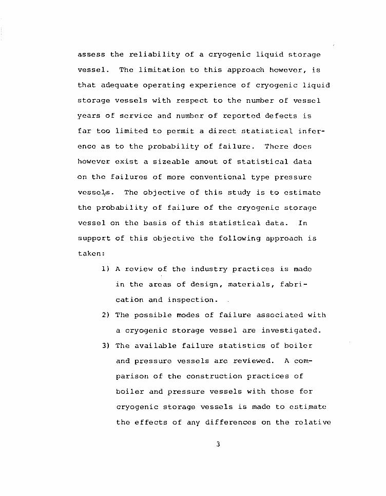
assess the reliability of a cryogenic liquid storage
vessel. The limitation to this approach however, is
that adequate operating experience of cryogenic liquid
storage vessels with respect to the number of vessel
years of service and number of reported defects is
far too limited to permit a direct statistical infer-
ence as to the probability of failure. There does
however exist a sizeable amout of statistical data
on the failures of more conventional type pressure
vessels. The objective of this study is to estimate
the probability of failure of the cryogenic storage
vessel on the basis of this statistical data. In
support of this objective the following approach is
taken:
1) A review of the industry practices is made
in the areas of design, materials, fabri-
cation and inspection.
2) The possible modes of failure associated with
a cryogenic storage vessel are investigated.
3) The available failure statistics of boiler
and pressure vessels are reviewed. A com-
parison of the construction practices of
boiler and pressure vessels with those for
cryogenic storage vessels is made to estimate
the effects of any differences on the relative

probability of failure of the two types.
4) Based on the above findings, an estimate is
made on the probability of failure of the
cryogenic vessel.
1.1 VESSEL
The basis for the assessment is a cryogenic storage
vessel which has been in service for approximately twelve
(12) years. The vessel can generally be described as a
flat-bottom, double-walled design with the inner vessel
having a rated capacity for holding 600,000 gallons of
liquid. As illustrated in Figure 1-1, the inner vessel
rests on foam block insulation and the annular space
between the inner and outer vessels is filled with perlite
powder insulation and the insulation is constantly purged
with dry nitrogen gas. The inner vessel is designed with
a vapor space equivalent to five percent of its rated
capacity. The change in pressure in the vapor space as
a result of boil-off, filling or withdrawing of liquid
is controlled by a pressure control system which main-
tains the vapor space below the design pressure. The
components in such a design which comprise the pressure
boundary include the inner vessel and the piping
connected to it which terminates at the thermal sleeves
on the outer vessel. Table 1-1 lists the pertinent
parameters of the vessel design.
4
y

:—r
Block Insulation
Outer Vessel
Inner Vessel
Perlite Insulation
Anchor Bar
CRYOGENIC LIQUID STORAGE VESSEL
FIGURE 1-1

TABLE 1-1
SUMMARY OF DESIGN PARAMETERS
Inner Vessel and Piping
Design Pressure 34.5 kPa(5 psig) plus Liquid Head (31145.4 kg/m-*(71.5 lb/ft3)
Design Temperature 77°K(-320°F)
Operating Pressure 20.7 kPa(3 psig)
External loadings Seismic-10%
Materials of Vessel: 9% Nickel Steel Construction Piping: 304 Stainless Steel
Construction Method Welded
Outer Vessel
Design Pressure .5 kPa(2 IN H2o) plus insulation
Design Temperature 29 4°K(70°F)
Material of Structural Carbon Steel Construction
Construction Method Welded

In normal operating service, the vessel is filled
to approximately seventy-five (75) percent of its rated
capacity. Part of this is held in reserve while the
balance is used in filling other smaller cryogenic
vessels. Over a period of one week, the liquid level
drops to twenty-five (25) percent of normal capacity
as a result of the filling operations.
1.2 LIMITATION IN SCOPE
The failure probability developed in this report is
based on normal operation of the vessel. It does not
include failures caused by accident conditions, natural
disasters or sabotage. The probability of vessel failures
from such accidents would have to be derived from system
analysis to determine the probability of the accident
and calculations to determine the resulting stresses in
the vessel.

2. CONSTRUCTION PRACTICES
2.1 INTRODUCTION
The quality level initially built into the vessel
considered here is an important factor in the expected
service reliability. This quality level is related
directly to the practices used to design and construct
the vessel. The documents which prescribed the material,
design, fabrication and testing requirements for the
vessel under study were provided by the following codes
and standards:
ASME Boiler and Pressure Vessel Codca, Section VIII, Division 1
ASME Boiler and Pressure Vessel Code, Code Case 1308-5
API Standard 620, Appendix R"
ANSI B31.3, Pressure Piping Code
API Standard 620, Appendix R'*>) is best suited for
a,design of the vessel type under study. These rules
cover the construction of large, flat bottom, welded,
low pressure above ground storage vessels. At the time
of vessel construction, this Appendix R was limited to
vessels containing refrigerated liquids with design aThe ASME Boiler and Pressure Vessel Code will be referred to elsewhere as the "ASME Code" along with its various sections.
Section I Power Boilers Section III Nuclear Power Plant Components Section V Non-destructive Examinations Section VIII Pressure Vessels (Division 1 and 2) Section IX Welding Procedures and Qualifications

temperatures down to 222°K(-60°F). The ASME Code(7)
however, along with Code Case 1308-5^) provided the
rules to meet the minimum design temperature require-
ments of 77°K(-320°F) .
Code Case 1308-5 established the requirements for
the use of the 9% nickel steel for the low temperature
service. It defines the material requirements for manu-
facturing including chemical composition, heat treatment,
tensile testing and impact testing. In addition, the
allowable stress levels and fabrication requirements,
including weld procedure and performance qualification
are also defined. As a result, a combination of API
Standard 620, ASME Section VIII and Code Case 1308-5
were used in the construction of the inner vessel.
The piping between the inner and outer vessels was
constructed to the rules of ANSI D31.3^9^. This section
of the pressure piping code covers the design and con-
struction of piping for use within a chemical plant or
petroleum refinery. In this section of the report, the
coverage and adequacy of the Codes of Construction are
reviewed along with the measures taken by the owner/
operator to enhance the quality level. From this review,
an assessment is made on the quality level of the vessel
and piping with respect to the level of those vessels
contained in the statistical data in Section 4.

2.2 MATERIALS
The materials of construction include quench and
tempered 9% Ni steel for the vessel and nozzles and 304
stainless steel for the annular space piping. In
selecting the materials for a low temperature application,
the primary concern is the effect of the low temperature
on the material toughness. 9% Ni steel was developed in
the 1940's to meet the needs of cryogenic applications.
The material has a relatively high strength and retains
high toughness levels down to liquid nitrogen tempera-
tures 77K(-320°F)(10-12)_ Tnc gGnGrai effect of a
decrease in temperature is an increase in the yield and
tensile properties of the material. As shown in Table
2.1, the yield and tensile strengths increase 56% and
52% respectively over room temperature strength prop-
erties for the 9% Ni steel. With the allowable stress
criteria for this vessel being based on the tensile
properties at room temperature, the result is a more
conservative design when operating at the low service
temperatures.
9% Ni steel has been used extensively in contain-
ments for the overseas transporting of liquefied natural
gas (LNG). Unlike stationary tanks, the tanks on LNG
carriers are subjected to static and dynamic loadings
resulting from ship motion. A fail safe approach has
10

TABLE 2.1
9% Ni Steel d2) 304 Stainless Steel (26)
294K(70°F) 77K(-320°F) 294K(70°F) 77K(-320°F) Tensile Strength, MPaW(KSI) 760(110) ,,=„„„,
/buuioj 1150(167) 566(82) 1524(221) Yield Strength, MPa (KSI) 585(85)
Elongation (50.8 mm) % 20
920(133) 241(35) 209(39]
32 60 40

been taken in the design of these vessels, e. i., the
vessel design is based on the 'leak-before-break
criteria * (13/14)< ^0 meet this criteria, extensive
fracture mechanics studies(14-24) have been conducted
to examine the configuration and propagation rate of
the through cracks in light of the fracture toughness
of 9% Ni steel. The results of these studies will be
used in Section 3 to assess the fracture behavior
related to this design.
Also shown in Table 2.1 are the increases in the
yield and tensile strengths of 304 stainless steel at
the operating temperature. The material has been found
to exhibit good ductility and toughness down to
20K(-423°F)(25). In addition, results of impact tests
indicate that the material is very stable over long
periods of exposure and does not exhibit any marked
degradation of toughness'^o).
2.3 DESIGN
The rules of the Codes of Construction to which the
vessel and piping were designed provide formulas which
establish the wall thickness necessary to maintain the
average membrane stress below the allowable stress
limits. The formulas are based on the assumption that
there is continuous elastic action throughout the member
and the stresses are evenly distributed. To account for
12

the high localized and secondary bending stresses which
exist when designing and fabricating to these design
rules, safety factors and design rules for details are
incorporated to hold such stresses at a safe level. The
design rules for details include such approaches as the
area replacement method for the reinforcement of
openings. With respect to safety factors, an allowable
membrane stress of 163.8 MPa (23,750 psi) for the 9%
nickel steel and 129.6 MPa (18,800 psi) for the 304
stainless steel was used in designing the vessel and
piping. By this criteria, a safety factor of 4 which
is based on the ultimate tensile strength of the materials
at room temperature has been built into the vessel design.
This margin of safety is further increased if the
increase in strength of the material is considered at the
operating temperature.
Additional safety factors are incorporated into the
design formulas to account for the type of weld design
and nondestructive testing. These will be noted when
discussing the various components.
2.3.1 LOADINGS. With respect to the inner vessel, the
significant loading conditions are the internal pressure
within the vapor space, the loading of the liquid head
and the reaction loads from the attachments. The most
critical attachments being the piping and the anchor
13

brackets. The pressure within the vapor space is held
constant whereas the change in liquid level as a result
of filling or withdrawing of liquid creates a cyclic
pressure loading condition. In addition to the internal
pressure and liquid head loads, the fill and withdrawal
pipes are subjected to thermal cyclic loading. The
effects of the cyclic conditions will be further inves-
tigated in Section 3.
2.3.2 SHELL. The shell of the vessel consists of six
(6) courses ranging in thickness from 6.35 mm at the top
to 8.66 mm at the bottom (.250 to .341 inch) with' four
(4) stiffening rings evenly spaced along the outside of
the shell. The shell was designed for the loadings due
to pressure within the vapor space and the liquid head
at the various levels. The wall thickness of the lower
three (3) courses was determined with a weld efficiency
factor of 1.0 while an efficiency factor of .85 was
used on the remaining courses. These efficiency factors
correspond to 100% and spot radiography of the shell
longitudinal welds. The courses were joined in the
longitudinal and circumferential direction by full
penetration, double butt-weld joints.
2.3.3 DOME (ROOF). The spherically shaped roof is
constructed from 4.76 mm (3/16 inch) thick plates which
14

are joined by double-lap weld joints. These joints are
designed to have a minimum overlap of 25.4 mm (1.0 inch)
with a 4.76 mm (3/16 inch) two (2) pass fillet weld
on the outside and a single pass seal, weld on the inside.
The wall thickness was established on the basis of the
external loads resulting from the weight of the insul-
ation and roof. The minimum wall thickness required to
withstand the internal loading due to 34.4 kPa (5 psig)
design pressure in the vapor space was determined to be
2.59 mm (.102 inch). In calculation this thickness, an
efficiency factor of .45 was incorporated into the
design formula. This factor includes a weld joint
efficiency factor of .56 and an allowable stress reduc-
tion of .80.
The joining of the dome ±o the shell is accomplished
by means of a compression ring. This ring is provided
for the purpose of resisting the circumferential force
at the juncture due to the pressure loading on the dome.
The rules for the design of this ring are defined in
API Standard 620 wherein the minimal cross sectional
area of the compression ring region is determined on
basis of an allowable compressive stress of 103.4 MPa
(15/000 psi). By this method, the design of the com-
pression ring exceeds the minimum area requirement by
30%. With regards to the weld design, a double full-
15

fillet lap joint with 4.76 nun (3/16 inch) fillet welds
was used in connecting the dome to the compression ring.
The shell to compression ring joint was a full pene-
tration weld with a 6.35 mm (1/4 in^^T) fillet weld on
the outside.
2.3.4 FLAT BOTTOM. As will illustrated in Figure 1.1,
the inner vessel and contents are supported by the block
insulation and concrete foundation under the entire flat
bottom section of the vessel. The forty-eight (48) anchor
bars which are evenly spaced and attached along the lower
end of the shell are provided to secure the inner vessel
and to resist the upward lifting force due to the pressure
loading of the vapor space and the liquid head. The
flat-bottom is constructed from 4.76 mm (3/16 inch) thick
plates and are joined by single two (2) pass fillet lap
joints. The outer section of the flat-bottom is comprised
of an annular ring 7.62 mm (.30 inch) thick and is butt
welded to provide a flat surface for connecting to,the
shell.
The shell to floor joint follows the weld design
rules outlined by the ASME Code Section VIII for the
forming of a corner joint. The attachment is made with
a full penetration butt weld and reinforced with a
6.35 mm (1/4 inch) fillet weld on the outside. This
joint will develop secondary bending stresses when
16

the shell is subjected to pressure from the liquid head
and vapor pressure. In analyzing this joint as a fixed
connection, the secondary bending stresses were found
to be within allowable limits for a more detailed stress
analysis<27"30).
The radial end force transmitted through the ring
acts on the single full-fillet lap joint which joins
the flat-bottom to the ring. In analyzing as a non-
symmetrically loaded fillet weld(31)t the stresses induced
by the radial end load for the maximum loading condition
is determined to be less than 20% of the allowable stress.
2.3.5 ANCHOR SYSTEM. The anchor bars are attached to
the side of the shell by means of a bracket and keeper
bar. The arrangement of a typical bar is illustrated
in Figure 2-1. During the assembly of the anchor system,
the welding of the keeper to anchor bar is completed
when the vessel is preloaded with water. This action
results in a loading on the foundation equivalent to
89% of the cryogenic liquid weight at maximum capacity.
The limitation in achieving equivalent liquid weight is
due to the higher density of the cryogenic liquid. At
various intervals during the filling operation, the
elevation of the foundation is measured and is again
checked when the vessel is drained. By securing in this
17

Keeper Bar
Anchor Bracket
Shell
Anchor Bar
TYPICAL ANCHOR ARRANGEMENT
FIGURE 2-1
18
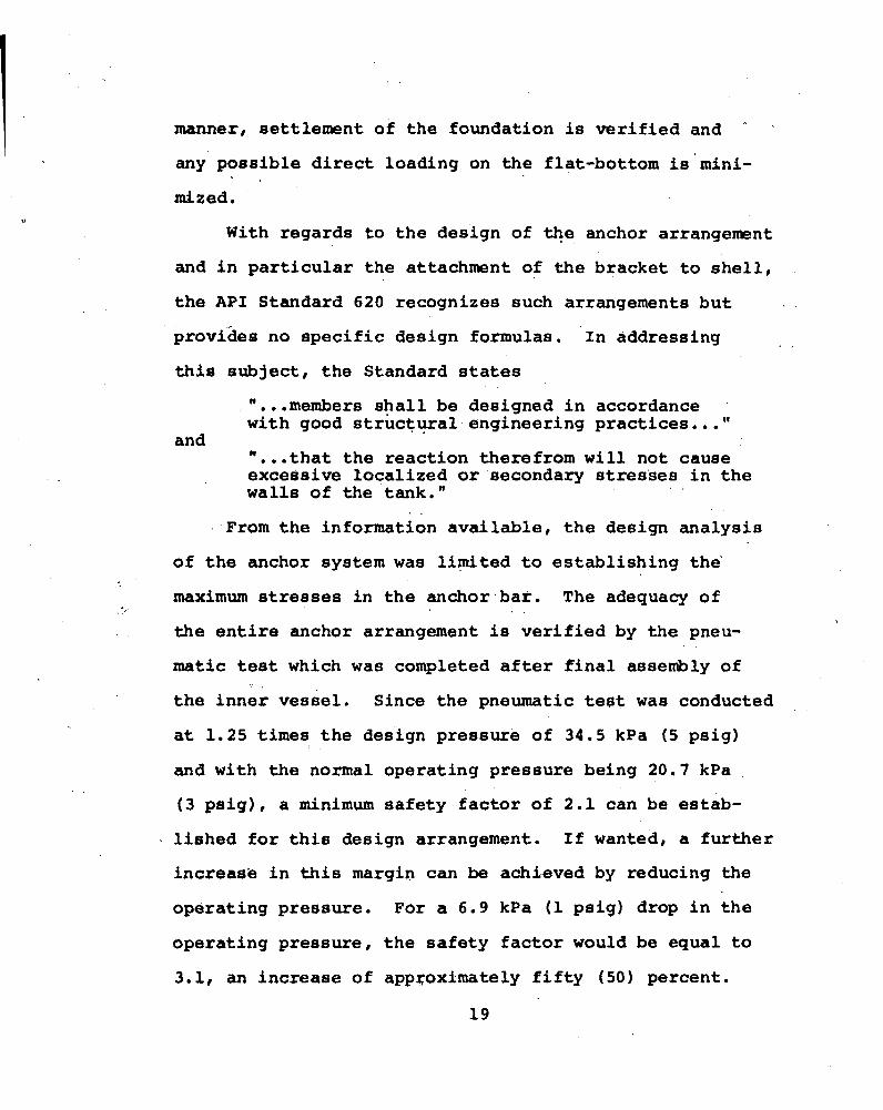
manner/ settlement of the foundation is verified and
any possible direct loading on the flat-bottom is mini-
mized.
With regards to the design of the anchor arrangement
and in particular the attachment of the bracket to shell,
the API Standard 620 recognizes such arrangements but
provides no specific design formulas. In addressing
this subject, the Standard states
"...members shall be designed in accordance with good structural engineering practices..."
and "...that the reaction therefrom will not cause excessive localized or secondary stresses in the walls of the tank."
From the information available, the design analysis
of the anchor system was limited to establishing the
maximum stresses in the anchor bar. The adequacy of
the entire anchor arrangement is verified by the pneu-
matic test which was completed after final assembly of
the inner vessel. Since the pneumatic test was conducted
at 1.25 times the design pressure of 34.5 kPa (5 psig)
and with the normal operating pressure being 20.7 kPa
(3 psig), a minimum safety factor of 2.1 can be estab-
lished for this design arrangement. If wanted, a further
increase in this margin can be achieved by reducing the
operating pressure. For a 6.9 kPa (1 psig) drop in the
operating pressure, the safety factor would be equal to
3.1, an increase of approximately fifty (50) percent.
19

Further assurance on the integrity of this design
arrangement can be realized when the following facts are
considered:
1) Except for the infrequent occasion when the
vessel is taken out of service, the loading
is steady on the anchor system.
2) The material possesses good ductile properties
and yielding at these highly stressed loca-
tions on the vessel will allow for the distri-
bution of these stresses to adjacent under-
stressed areas.
Also to be noted is the fact that the failure of the
anchor system would be a reBult of overpressurization.
Therefore, failure of the anchor system is directly
related to the probability of failure of the safety
relief devices to function.
2.3.6 NOZZLES. A total of ten (10) nozzles ranging
in pipe size from 1 to 18 inches penetrate the boun-
daries of the vessel. By the design rules of API
Standard 620, the attachment of these nozzles requires
that a minimum reinforcement be added to compensate
for the weakening effect of the opening. The design
rules are based on the commonly known "area replacement
method" which requires sufficient reinforcing material
20

V I
to be placed immediately adjacent to the opening in a
prescribed manner to evenly distribute the stress
concentrations. The method is simple in approach and
has been verified by both analytical and experimental
techniques ^-2-35) # rpjjg design rules determine the
amount of reinforcement as well as the boundary limits
for the reinforcing material to be effective. The
design rules are limited, however, to determining
the reinforcement for the internal pressure loadings
of the vessel. For the external loadings associated
with the piping, other methods, not provided by either
API Standard 620 or ASME Code, need to be used to
determine the effects on the vessel.
For this reason a detailed analysis was performed
on a typical nozzle attachment. The 4 inch product
outlet line which is connected to the flat bottom
floor was selected and analyzed using the' computer
program, Pipdyn II. The results of this computer
analysis provided the reaction loads which would be
transmitted through the nozzle onto the vessel. In
establishing these reactions, the loadings due to
pressure and deadweight, along with thermal movement
of the vessel and piping, were considered in the
analysis. The reaction loads from this analysis were
then used to determine the local stresses in the area
21

of the nozzle attachment^36). By this approach, the
stresses were found to be within the allowable stress
criteria as defined by Division 2 of ASME Code Section
VIII.
In continuing the investigation on the adequacy of
the nozzle design, the nozzle attachment was reviewed
, for its resistance to fatigue. This area of the vessel
represents the greatest exposure to cyclic loads. In
addition, from the failure statistics on pressure
vessels, a large number of failures are attributed
to fatigue at the nozzle attachment. The Codes of
Construction require cyclic loadings to be considered.
but provide no specific details on their treatment.
The fatigue evaluation was based on the set of
rules in Division 2 of the ASME Code, Section VIII.
The rules evaluate the need for a detailed fatigue
analysis on the basis of the number of cyclic loads
and resulting stresses and the temperature differences
between points within the area being studies. In this
evaluation, the cyclic loadings due to piping reactions
were also considered. By this approach, the nozzle area
met all the applicable requirements of the rules and
further analysis was not necessary.
22

2.3.7 PIPING. The piping in the annular space
contains such construction features as seamless pipe
and full penetration butt weld joints. The significant
loadings imposed on the piping are a result of the
effects of thermal contraction. The piping which
serves in the filling or withdrawing of liquid from
the vessel are also exposed to thermal cycling which
occurs during the filling or withdrawing operation.
To account for the effects of thermal contraction,
the piping runs contain loops to provide the needed
flexibility. The loops are designed to minimize the
reaction loads acting on the vessel and to keep the
stresses in the pipe run within acceptable limits.
By the empirical equation in the Piping Code, suffi-
cient flexibility exists in the pipe runs and further
detailed analysis is not required. Using this equa-
tion, however, the Piping Code warns that there is no
assurance that the reaction loads will be acceptably
low. In order to confirm the adequacy of the piping
flexibility, the computer analysis of a typical line
as previously described was completed to determine
the reaction loads and the stresses within the piping
run. The reaction loads were shown to be Of no conse-
quence in the analysis of the nozzle to shell attachment,
The ANSI B16.3 Piping Code recognizes the effects
23
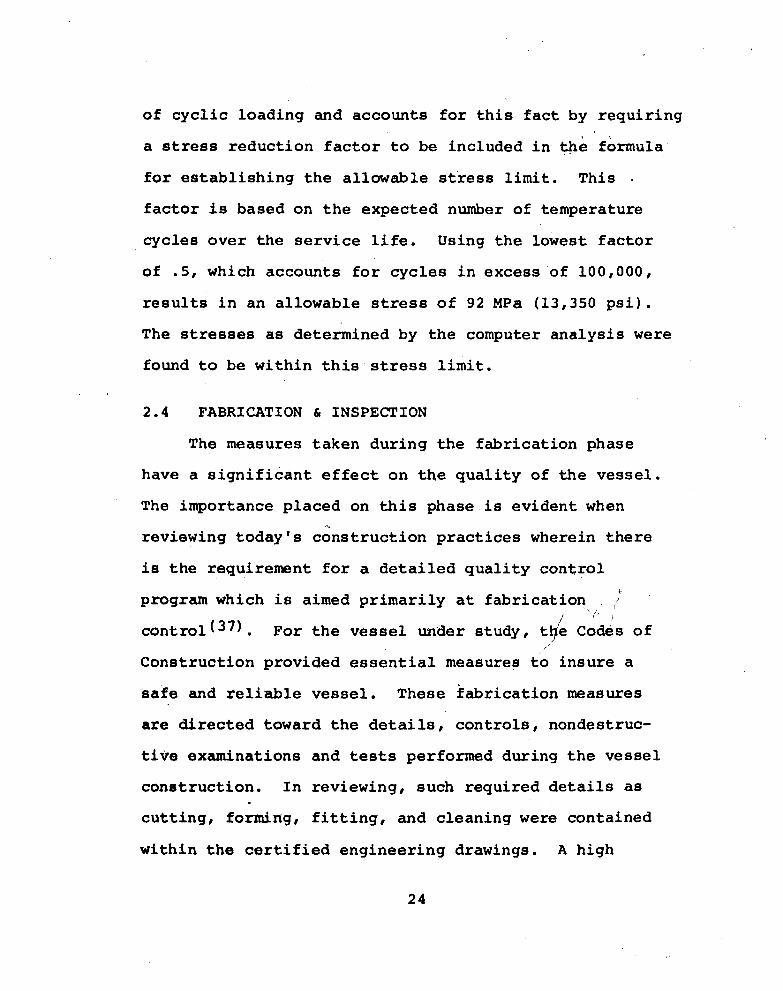
of cyclic loading and accounts for this fact by requiring
a stress reduction factor to be included in the formula
for establishing the allowable stress limit. This •
factor is based on the expected number of temperature
cycles over the service life. Using the lowest factor
of .5, which accounts for cycles in excess of 100,000,
results in an allowable stress of 92 MPa (13,350 psi).
The stresses as determined by the computer analysis were
found to be within this stress limit.
2.4 FABRICATION & INSPECTION
The measures taken during the fabrication phase
have a significant effect on the quality of the vessel.
The importance placed on this phase is evident when
reviewing today's construction practices wherein there
is the requirement for a detailed quality control
program which is aimed primarily at fabrication
control(37)# For the vessel under study, the Codes of
Construction provided essential measures to insure a
safe and reliable vessel. These fabrication measures
are directed toward the details, controls, nondestruc-
tive examinations and tests performed during the vessel
construction. In reviewing, such required details as
cutting, forming, fitting, and cleaning were contained
within the certified engineering drawings. A high
24

degree of control was found to be exercised in the area
of material and welding. Material control can be traced
to the time of material manufacture where additional
testing was completed to assure the strength, ductility
and toughness of the material to meet the low tempera-
ture service.
As the material was received at the job sight, it
was visually inspected for defects and checked for
traceability to the mill test reports by owner/operator
Inspectors. Material identification during construction
was established by the assigning of a unique piece mark
utilizing the drawing number as the prefix. This piece
mark identification is shown on the drawing for the
particular item and was affixed by the fabricator on
each item upon receipt from the material manufacturer.
This identification practice is an important aid in
preventing the use of improper or nonconforming
materials during fabrication.
In the area of welding, controls were established
over the three (3) key elements which, in combination,
make it possible to repeatedly achieve welds of suitable
quality and known properties. The three (3) key
elements include the weld procedure, welder, and
examination of the weld.
Weld procedures were generated to define and docu-
25
merit the essential details in welding the specific
materials. Such details as process, base metal, filler
metal, joint configuration and power input were included
as part of the weld procedure. These procedures were
also qualified in accordance with the requirements in
Section IX of the ASME Code. The procedure qualifi-
cation was based on the results of testing to determine
the strength, ductility, soundness, and adequacy of
fusion. This testing was conducted at the minimum
design temperature as was the additional impact testing
to determine the notch ductility of the weld metal and
the heat affected zone.
Control df the welder was maintained by qualifying
the welders to the applicable requirements in Section IX
of the ASME Code. By these requirements, welders were
qualified on the basis of testing to produce a sound
weld in accordance with the qualified weld procedure.
The testing also included details which, for the most
part, represent the actual weld conditions to be encoun-
tered during fabrication. Also, as part of the welder
control, records of ti\e qualifications on each welder
were maintained by the fabricator and each welder was
assigned an identifying symbol which was stamped by
the welder on his work. x
With regards to examination, the measure of soundness
26
and final quality of the welds is based on the number
and extent of nondestructive examinations conducted
and the sensitivity of the methods employed to detect
any flaws within the welds. The nondestructive exam-
ination program utilized in the construction included
visual, radiographic, liquid penetrant, solution film,
and vacuum box examinations. The longitudinal joints
in the lower three (3) courses of the shell and all
weld joints in the piping were 100% radiographically
examined. Spot radiography was conducted on the
remaining longitudinal and all circumferential welds
in the shell. Liquid penetrant examination was used
to detect any surface flaws after the removal of tem-
porary attachments and on the corner weld that joins
the shell to the flat bottom. The dome was inspected
by solution film examination and the flat-bottom lap
joints were examined by the vacuum box technique.
The nondestructive examinations were performed
by trained personnel to the requirements and acceptance
standards established by Section V of the ASME Code.
The acceptance standards for each specified nondes-
tructive examination has evolved from experience over
the years. They are based on high fabrication quality
through superior workmanship using proven fabrication
practices. Service experience with pressure vessels and
27

boilers has demonstrated the general adequacy of these
standards.
Another noteworthy point concerning the nondes-
tructive examinations is the time of performance. For
this purpose, the performing of these examinations is
discussed with respect to the hydro-pneumatic test.
Prior to this test, the radiographic, liquid pene-
trant, and vacuum box examinations were completed in
the particular areas. The vessel was given a visual
examination after filling with water and once again
after reducing the pressure from the test to operating
condition. At this time the dome was inspected by
solution film method. A visual examination was also
made on the anchor system after draining the vessel
and repressurizing to design condition. After com-
pleting all testing, the flat-bottom and corner weld
of the shell to flat-bottom were once again examined
by the vacuum box technique.
The performance of these nondestructive examinations
however, does not assure that all flaws will be detected
since the examination techniques do have limitations in
detecting certain flaw geometries. In addition, human
error also limits the effectiveness of the nondestructive
program. To compensate for these limitations, relia-
bility is best assured by the use of materials which have
28

toughness characteristics to meet the conditions of
service. As will be shown in Section 3, the materials
of construction possess these toughness characteristics
which make them tolerant to flaws.
2.5 TESTING
As mentioned, a hydro-pneumatic test was performed
following the completion of fabrication. The test sub-
jected the vessel to an overpressure of 25% greater than
the design pressure. Except for very localized areas of
geometric discontinuities, the stress created by this
test is significantly below the yield point of the
materials of construction. For the major portion of
the design, the test stress is well within the elastic
range.
By this test the vessel integrity is confirmed by
exposing excessive deformations, faulty materials, or
leaks. The test also provides a means of attaining
shakedown in localized stress regions where peak
stresses exceed the yield strength. Shakedown by
local plastic deformation permits subsequent loading
responses to be elastic.
2.6 ADDITIONAL MEASURES
The owner/operator took several noteworthy steps
in an effort to achieve a vessel of highest quality.
29

These measures included the following:
A design specification was prepared wherein the
specific functions and complete range of operating
conditions were defined. In addition, thermal and
mechanical loads which the vessel Would be expected
to withstand during service were detailed in the
specification. From the failure statistics, a number
of the vessel failures reported are associated with
conditions not intended by design. The importance
of the design specification in establishing the design
parameters is recognized by the ASME Code and is a
requirement for Section VIII Division 2 and Section
III vessel designs.
All engineering documents were required to be
submitted to the owner/operator for approval. These
documents included such items as the detail drawings
of the vessel and piping, design calculations, and
welding procedures. These documents were reviewed by
the competent individuals involved in generating the
design specification. In addition, certified as-built
drawings were required after completion of the vessel.
The owner/operator furnished on-site inspection to
monitor all operations, examinations and tests. In
addition, the owner/operator required the right to
witness fit-ups, welding, and nondestructive testing
30

and to review such items as reports of examinations
and tests, radiographs, repair procedures. This
measure, along with the document approval requirement,
can be considered as fulfilling the inspection require-
ment of the Codes of Construction.
2.7 ADEQUACY OF THE CONSTRUCTION PRACTICES
The review provides strong evidence to support
the belief that for the intended service the quality
level is comparable to and in some areas better than
that of the high quality vessels that form the basis
of the failure statistics. The reasons can be
summarized as follows:
1) Extensive studies have established the behavior
of the materials of construction at the low temperature
service for this design and the suitability of these
materials has been demonstrated by the acceptable
service performance in vessels of similar construction.
In addition, the control measures to establish the
strength, toughness and ductility at the low temperature
assures consistent material properties. These same
controls were imposed on the weld and heat affected zone
to assure the same mechanical properties as the base
metal.
2) The design of the pressure boundary components
31

was based on the design formulas in Division 1 of the
ASME Code, Section VIII using an allowable stress limit
equal to one-fourth (1/4) the ultimate tensile strength
and the applicable efficiency factors. The detailed
analysis of the more critical areas where local stresses
could be significant showed the stresses to be within
the allowable limits as defined for the type of analysis.
The computer analysis of a typical pipe line demonstrated
the adequacy of the piping design. The loops within the
lines provide adequate flexibility to keep the reaction
loads on the vessel and the stresses within the pipe to
acceptable limits.
3) The design specification prepared by the owner/
operator defined the appropriate design and operating
conditions of the system. The requirement for docu-
ment approval by the owner/operator provides assurance
that the manufacturer properly interpreted the design
specification and provided another check for any gross
oversights which could potentially lead to a failure.
32

3. POSSIBLE MODES OF FAILURE
3.1 INTRODUCTION
By ASME Code criteria^387, the modes of failure to
be considered when designing a pressure vessel include:
(1) Plastic collapse
(2) Excessive deformation
(3) Instability
(4) Fatigue failure
(5) Material failure
(a) Brittle fracture
(b) Creep
(c) Corrosion
Not all are relevant to a design of the type under study
and some failures result from a combination of the above
modes as will be discussed.
Instability which may be elastic or inelastic is
generally associated with compressive stresses in thin
members and would not be a dominating factor in this
internally pressurized vessel. Likewise, creep failure,
which is a result of slow continuous plastic deformation
shown by materials at elevated temperatures, would not be
possible at the low temperature.
With the system designed to the codes of construction
previously discussed, failure by excessive elastic or
plastic deformation is extremely remote. As discussed
33

the design formulas are based on elastic stress analysis
and incorporate a safety factor of four (4).
Of the more common types of corrosion, stress
corrosion is an important consideration for many vessels
because of the wide range of susceptible materials and
aggressive environments. To date, however, stress
corrosion has not been reported to occur at cryogenic
temperatures(39,40). The reason for stress corrosion
being less a problem in cryogenic designs is attri-
buted to the low temperatures which preclude the exis-
tence of an aggressive environment. Hydrogen embrit-
tlement is also classified as a form of corrosion. With
high strength steels, embrittlement can occur giving low
ductility resulting in brittle type failures associated
with delayed cracking. At cryogenic temperatures, how-
ever, cracking due to hydrogen embrittlement has not been
observed(39»4*) .
The brittle fracture and fatigue modes of failure
are the most common types of pressure vessel failures
and present the greatest concern. Brittle fracture is
the most dangerous of the failure types since it occurs
at stresses considerably below the yield point and with-
out prior noticeable deformation. Service failures have
shown that brittle fractures are initiated by small flaws
that grow to critical size^42^. The temperature of the
34

material as well as the stress state also contribute in
the failure mechanism.
Fatigue is considered to account for a larger per-
centage of failures and often precedes the onset of
brittle failure. Since the end result of fatigue failure
is not always catastrophic, fatigue failure is normally
ranked second in importance to brittle fracture, even
though it is more common.
The key element in these types of failures is the
initiation or existence of a flaw or notch. In reality,
all vessels will contain flaws of some type or size such
as metal imperfections, weld defects or local variations
from the design geometry or surface finish. The nondes-
tructive testing and inspection during the fabrication
phase provide a means for minimizing these flaws.
3.2 FRACTURE MECHANICS APPROACH
Linear elastic fracture mechanics provides an
approach to fracture control and is used in this study
to assess the fracture safeness of the design. This
approach has been adopted by the ASME and is incorporated
into Section III and Section IX for the design and evalu-
ation of flaws of nuclear pressure vessels. The fracture
mechanics approach to fatigue assessment makes the assump-
tion that cracks or crack-like discontinuities are present
from the onset. Therefore, the problem of crack initia-
35

tion is of no consequence and only the crack propagation
need be considered in the fatigue process. In applying
the fracture mechanics to design, the material proper-
ties of interest are the fracture toughness which is
used to compute critical crack sizes and the fatigue
crack growth rate which is used to estimate the cycle
life expectancy ^29f 42) .
3.3 FRACTURE MECHANICS ANALYSIS<29r43,44)
To assess the fracture resistance qualities of the
design, a fatigue crack growth analysis was performed.
Crack depths varying from 2.16 to 6.35 mm (.065 to .250
in) were analyzed to determine the sensitivity of the
results to the initial flaw depth assumption. The flaws
are assumed to be located in the shell, nozzle and piping.
3.3.1 CYCLIC CONDITIONS. The design cyclic conditions
are based on a conservative estimate of the magnitude
and frequency of the temperature and pressure transients
which result during normal operation. The cyclic pressure
loading is a result of the change in liquid head which
occurs on a weekly basis. During periods when there is
no withdrawing of liquid from the vessel, the associated
piping in the annular space will begin to warm. A tem-
perature gradient develops through the length of the line
due to the cold inner vessel and ambient temperature
36
conditions of the outer vessel. To account for this
condition, the very conservative assumption is made
that the temperature in the entire line through to the
nozzle connection rises to ambient state once a day.
The total number of cycles for these transient condit-
ions are assumed to occur over an estimated forty (40)
year operating life. i;
3.3.2 STRESSES. The stresses used for this evaluation
appear in Table 3.1 and are derived from the review
conducted in Section 2. The shell stress represents the
highest circumferential value as a result of the change
in liquid head. This stress condition occurs in the
lower shell course.
The nozzle has several regions of high stresses but
one of the more critical locations is the inside corner
where stresses provided by pressure can be three (3)
times the average membrane stress. The evaluation
focuses on this location and is based strictly on the
pressure cyclic loading condition. It' is recognized
that nozzle loads of the type due to temperature effect
this nozzle region, however, the available published
papers are.limited to analyzing the effects of internal
pressure only.
The results of the stress analysis on the piping
indicate the circumferential stresses due to internal
37

pressure to be far less than the stresses created by the
bending mements within the line. For this reason, the
analysis is based on the existence of a flaw lying in the
circumferential direction of the line,
3.3.3 STRESS INTENSITY FACTORS. For an analysis of
this type, assumptions regarding the location, orientation,
and size of cracks which could exist needs to be made.
The worst type of flaw which can be postulated is a
surface crack on the inside. For the shell, the most
detrimental orientation for this assumed flaw is perpen-
dicular to the maximum principal stress, i.e. axial. As
already noted, the assumed flaw in the piping is assumed
to be normal to the axial stresses while the flaw in the
nozzle is assumed to be located on the inside corner as
shown in Figure 3-1.
The assumed shape of the flaw needs also to be con-
sidered. For the piping and shell, a semi-elliptical
shape, with a length to depth ratio of six (6), was used.
This reasonably characterizes the type of flaws reported
within a pressure vessel(43)#
Since the fracture,mechanics approach to the design
against failure is basically a stress intensity consid-
eration, an expression which relates the material para-
meters, stresses and defect information in terms of stress
intensity is required for the analysis. The expressions
38
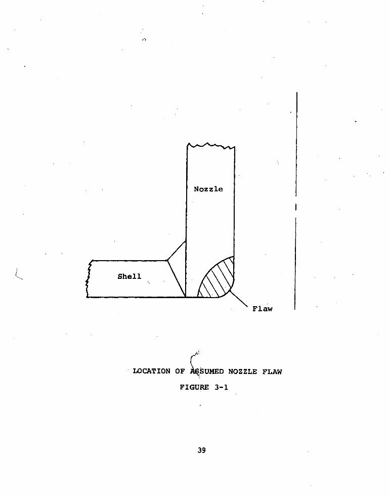
Shell
Nozzle
Flaw
LOCATION OF ASSUMED NOZZLE FLAW c
FIGURE 3-1
39

for the analysis were taken from the work ^5) sponsored
by the Pressure Vessel Research Committee (PVRC) of the
Weld Research Council (WRC). This work contains the
recommendations of the PVRC to the ASME on the toughness
requirements for vessels built to Section III.
3.3.4 FRACTURE GROWTH. From the work of Paris<46), the
crack propagation rate of existing flaws in a structure
caused by cyclic loading is primarily a function of the
range of applied stress intensity factor, AK. In general,
fatigue crack growth data is correlated reasonably well
by the expression
da/dN = C(AK)n
where n is the slope of the log da/dN versus log AK and
C is a scaling constant. This expression can be used to
derive the number of cycles required to extend the
assumed initial crack to a size that will penetrate
through the thickness of the wall. The general form of
the equation is (47);
N *> 2 ajn-2/2 afH-2/2
i—/
(n-2) C Mn/2 Acrn
where C and n are as described above and
a^: assumed initial crack depth I
af: thickness of vessel under investigation
a: the applied cyclic load range
M: flaw shape factor
. 40
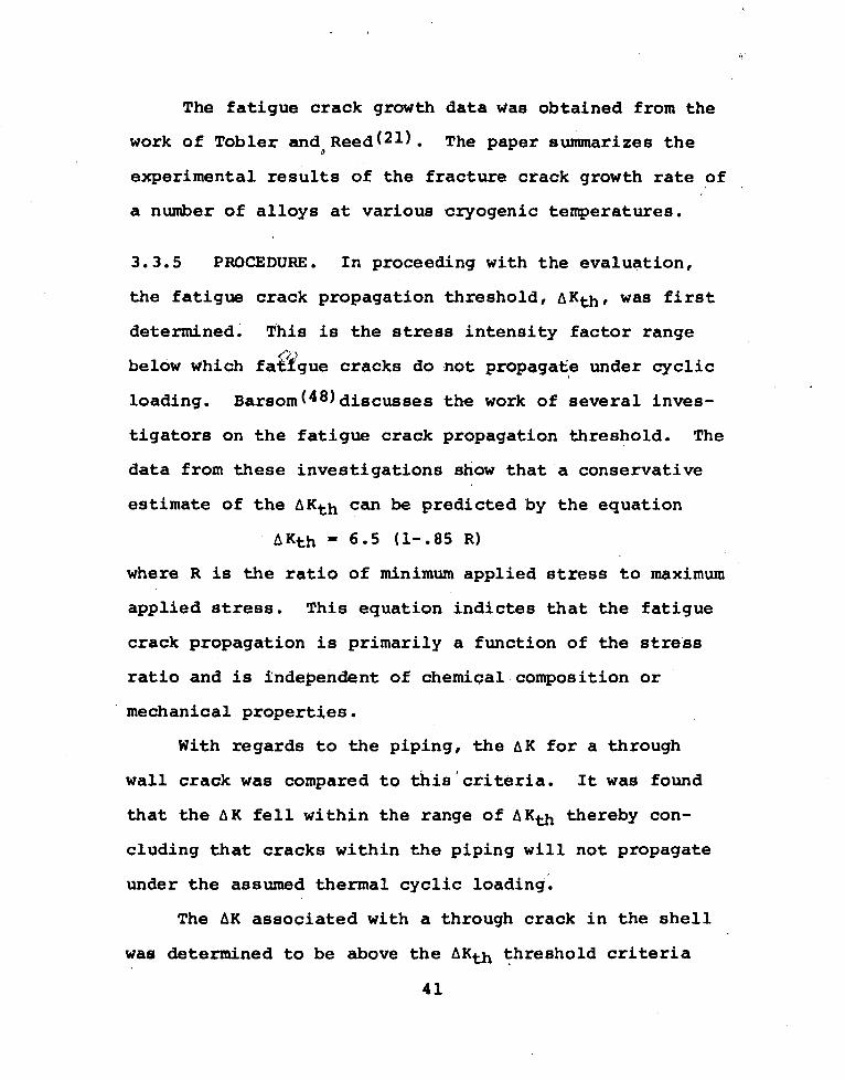
The fatigue crack growth data Was obtained from the
work of Tobler and Reed(21). The paper summarizes the
experimental results of the fracture crack growth rate of
a number of alloys at various cryogenic temperatures.
3.3.5 PROCEDURE. In proceeding with the evaluation,
the fatigue crack propagation threshold, AK^, was first
determined. This is the stress intensity factor range
below which fatigue cracks do not propagate under cyclic
loading. Barsom^8) discusses the work of several inves-
tigators on the fatigue crack propagation threshold. The
data from these investigations show that a conservative
estimate of the AKt^ can be predicted by the equation
AKth - 6.5 (1-.85 R)
where R is the ratio of minimum applied stress to maximum
applied stress. This equation indictes that the fatigue
crack propagation is primarily a function of the stress
ratio and is independent of chemical composition or
mechanical properties.
With regards to the piping, the AK for a through
wall crack was compared to this criteria. It was found
that the AK fell within the range of AK^ thereby con-
cluding that cracks within the piping will not propagate
under the assumed thermal cyclic loading.
The AK associated with a through crack in the shell
was determined to be above the AKtn threshold criteria
41

but below the AK range of the available fatigue crack
growth data. For the purpose of this evaluation, the
assumption is made that fatigue crack propagation occurs
and is based on the fatigue growth data.
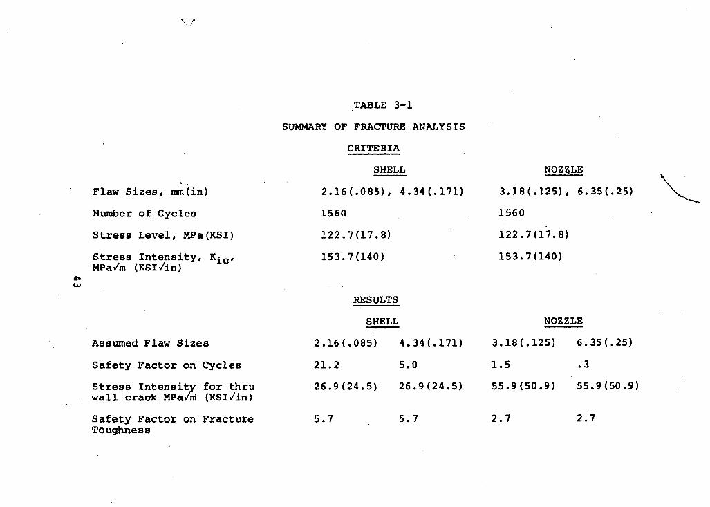
On the basis of the preceeding information, the
following evaluation was made.
(1) Using the initial and final through wall
crack sizes along with the applied cyclic
stress from Table 3-1, the number of cycles
to cause a crack to propagate through the
wall was determined.
(2) The calculated number of cycles was compared
to the estimated cycled to establish a
safety factor with respect to cycles to
cause crack propagation through the wall.
This value is shown in Table 3.1.
(3) The stress intensity factor associated with
a through wall crack was determined and
compared to the fracture toughness, K^c,
which would Cause an unstable condition.
This ratio also appears in Table 3.1 as
the safety factor with respect to fracture
toughness.
42
\/
Flaw Sizes, mm(in)
Number of Cycles
Stress Level, MPa(KSI)
Stress Intensity, K^c, MPa/m (KSl/in)
Assumed Flaw Sizes
Safety Factor on Cycles
Stress Intensity for thru wall crack MPa/ni (KSl/in)
Safety Factor on Fracture Toughness
TABLE 3-1
SUMMARY OF FRACTURE ANALYSIS
CRITERIA
SHELL
2.16(.085), 4.34M71)
1560
122.7(17.8)
153.7(140)
RESULTS
SHELL
2.16(.085) 4.34M71)
21.2 5.0
26.9(24.5) 26.9(24.5)
5.7 5.7
NOZZLE
3.18(.125), 6.35(.25)
1560
122.7(17.8)
153.7(140)
NOZZLE
3.18(.125) 6.35(.25)
1.5 .3
55.9(50.9) 55.9(50.9)
2.7 2.7

3.3.6 DISCUSSION OF RESULTS. The analysis provides a
quantitative means in assessing the fatigue resistance
and fracture toughness of the design. The results
indicate the nozzle to be the most susceptable having
the lowest margin with respect to both number of cycles
and fracture toughness. The margin would be somewhat
lower if the effects of the nozzle loadings were con-
sidered. There is, however, some degree of conservatism
in the stress intensity value K^c which was used./ The
stress intensity value is based on section thicknesses
greater than those in the vesse^-^A decrease in thick-
ness would lower the con&t/raint around a crack thus
giving an increase in fracture toughness. The increase
in fracture toughness with decrease of section size was
demonstrated on the 9% Ni steeld^) . Fracture toughness
values for 6 to 12mm sections, typical of the size range
of this design, generally ranged thirty (30) to seventy
(70) percent higher than those for sections around 30mm
thick.
Finally, with respect to the nozzles, a crack
located in this region should only propagate a limited
distance into the vessel where relatively low stresses
would permit crack arrest.
The results also demonstrate that the vessel design
supports the leak-be,f ore-break concept, that a detectable
44

leak can be supported by the material without resulting
in disruptive failure. The use of this concept, however,
would require the installation of leak detection equip-
ment to monitor the annular space. This approach has
been taken in the design of LNG tanks where fracture
mechanism analysis is used to compute the minimum flaw
size that will allow leakage of sufficient gas to be
sensed by the detector(13,14).
In summary, the results demonstrate the high toler-
ance the materials of construction have to flaws. In
addition, fatigue failure in the piping is unlikely and
failure by brittle fracture appears extremely remote.
3.4 ACCIDENT CONDITIONS THAT COULD CAUSE VESSEL FAILURE
The causes and consequences of all accidents that
could conceivably lead to loss of vessel integrity are
not considered in this report. Sighted below are some
examples of possible accidents not covered by the failure
statistics discussed in Section 4.
Overpressurization: Overpressurization may occur
due to failure of the safety relief devices to function
or could result from inadequate pressure relieving
capacity conditions not covered by the design specifi-
cation. Depending on the pressure, the vessel could be
expected to withstand minor distortion or in the unlikely
event of gross overpressurization, complete distortion.
. 45

To minimize the potential for failure by overpressuri-
zation, the owner/operator has incorporated redundant
safety devices. The effect of the redundant safety
relief system is a probability to failure by overpres-
surization of 1 X 10~7 events per year.
Copldown: Failure to slowly cool down the vessel
when bringing it into service could lead to a prohibi-
tive material temperature condition. Such an event
increases the potential for crack initiation and/or
growth.
Seismic: Postulated vessel failures caused by an
earthquake could result from failure of the support
system, piping failures, or nozzle failures. The anchor
support rods have been designed to take into account
earthquake factors of 1.1 'g'.
46

4. FAILURE STATISTICS AND FAILURE PROBABILITY
4.1 APPROACH
Operating experience with cryogenic vessels is
inadequate, both with respect to the number of vessel-
years of service and the number of known failures, to
permit a direct statistical determination of the proba-
bility of failure. For this reason, the following
approach is taken which involves
1. Consideration of operational and failure data
for other types of pressurized components,
such as boiler drums and unfired pressure
vessels.
2. Comparison of the design, construction,
inspection, and operating procedures used
for boiler drums and unfired pressure
vessels, and estimation of the effects of
any differences on the relative probability
of failure of the two types of vessels.
3. Utilization of the information from the above
steps, to assess the probability of disruptive
failure for the cryogenic storage vessel.
4.2 DEFINITION OF FAILURE
The words "accident" and "failure" have been used
in the various reports available to cover a wide range
of incidents requiring pressure vessels or boilers to
47

be taken out of service for repairs. To establish a
definitive basis for the analysis of vessel performance
Statistics, "vessel failure" is defined herein as a
condition in which a crack, leak, or other defect has
developed in the pressure retaining components of the
vessel, requiring repair or replacement of the vessel.
Two classes of failure are considered: 1) noncritical -
a local degradation of the pressure vessel boundary,
limited to localized cracks which may or may not result
in leakage; 2) potentially disruptive and disruptive -
a potential or actual breaching of the vessel by rupture
of the shell, head or nozzle, leading to rapid release
of a large volume of the contained pressurized liquid.
4.3 AVAILABLE FAILURE STATISTICS
4.3.1 U.S. PRESSURE VESSEL STATISTICS(49,50). Tne
failure statistics collected within the U.S. are a
result of the efforts by the nuclear industry. The statis-
tical population is predominantly for fossil-fueled
boiler drums used by electric utilities in the generation
of electricity. The most meaningful statistics come
from a survey in which the Edison Electric Institute
(EEI), American Boiler Manufacturer Association (ABMA)
and National Board of Boiler and Pressure Vessex
Inspectors (NBBPVI) provided information to the U.S.
Atomic Energy Commission (USAEC) on pressure vessels
48

constructed to ASME Section I and Section VIII. The EEI
and NBBPVI information dealt with operating experience
while the ABMA data pertained to fabrication information.
The EEI data included 5120 vessels which had experienced
22/692 vessel service years with only one occurrence of
a noncritical event. The ABMA data pertaining to the
number of ASME Section 1 and Section VIII pressure
vessels for fossil fueled fired water-tube boilers
installed in central station electric utility plants
cover over 33,000 vessels for the surveyed period.
Most of these vessels were ASME Section 1 steam drums
and headers. The ASME Section VIII vessels were prin-
cipally feedwater heaters. To obtain a larger and more
significant vessel population, the data was extrapolated
back in time to estimate the total number of comparable
pressure vessels manufactured for central station boilers
and feedwater heaters. The period chosen corresponded
to service years from 1943 to 1972. The extrapolation
was based on the reported statistics of the ABMA for the
number of vessels manufactured. The results provided a
conservative estimate of 68,317 vessels with 725,170
vessel years of service. Based on this extrapolated
data along with the fact there were no critical failures
reported, an upper limit (99% confidence) probability of
a disruptive failure event occurring in any one vessel
49
year during any one service year was determined to be
no greater than 6.3 X 10"6.
4.3.2 UNITED KINGDOM PRESSURE VESSEL STATISTICS. Stat-
istical data on pressure vessel failures in the U.K. have
been reported in three (3) surveys(51-53) which span the
years 1962-19 78. The most recent by Smith and Warwick
includes the 103,000 vessel years of the first survey,
1962-1967, the 105,400 vessel years of the second survey,
1967-1972 and the 104,370 vessel year covering 1973-1978
with some 20,000 pressure vessels and piping being
reported. The vessels which are predominantly from
power plant service include those built to design codes
similar in construction to ASME Section VIII. The piping
included in the survey reflects that built to comparable
pressure vessel standards. Results of the survey indi-
cate that for the 20,000 pressure vessels with over
310,000 vessel years of service, the critical failure
rate averages 4.2 X 10~5 per vessel year and for a 99%
confidence limit the value is 8.3 X 10 per vessel
year. The terms potentially dangerous and catastrophic
as used in the survey are judged to relate to the
failure categories as defined in this report. The
report also contains information on the defect causes,
mechanisms, location and materials involved. In reviewing
the reported critical failures, the following statistics
50

were derived: 1) Of the reported failures, 73% were
associated with vessels having less than 10 years of
service. This tends to support the ASME philosophy,
which by Section XI requires more inspection early in
the vessel life as opposed to the more traditionally
evenly spaced inspection intervals. 2) Piping failures
accounted for 64% of the failures. 3) There were six
(6) failures related to failure modes not relevant to
a cryogenic application. Excluding these failures,
the probability of failure instead of being 4.2 X 10~5
would then be 1.6 X 10"^ for a critical failure.
4.3.3 FEDERAL REPUBLIC OF GERMANY PRESSURE VESSEL FAILURE STATISTICS. The Institut fur Reactor-
sicherheit der Technischen Uberwachungs-Vereine (Institute
for Reactor Safety of the Technical Inspection Associa-
tions) has, on a continuing basis, accumulated the largest
body of pressure vessel data available in the world. The
statistics represent a rapidly increasing number of
vessels and vessel-years of operation. As of 1972, there
were over 470,000 vessels in the data set comprising over
4.3 million vessel years of service. However, little is
published regarding the design, fabrication, and opera-
ting practice for many of these vessels.
These statistics have provided the basis for several
papers giving studies of failure probabilities. From
51

these studies, failure rates have been determined to
be in the range from .27 X 10-5 to 6.9 X 10⁻⁵(54,55).
4.4 PROBABILITY OF A DISRUPTIVE PRESSURE VESSEL FAILURE
On the basis of the first U.K. survey and the other
sighted vessel statistics, the Advisory Committee on
Reactor Safeguards concluded(49) that an appropriate
99% confidence upper bound for probability of critical
failure of non-nuclear vessels to be less than 1 X 10~5
per vessel year. In arriving at this value, the ABMA
data was recognized as the most useful and significant
having the largest data base. This same value was also
concluded in a later report by Bush'5*>) j.n which the
same failure statistics were examined along with the
second U.K. survey. The conclusions from these studies
are generalizations and provide some indication of the
norm that has been achieved with current standards of
design, materials, construction and inspection.
4.5 DIFFERENCES BETWEEN BOILER PRACTICE AND CRYOGENIC PRACTICE
The assessment of the cryogenic storage vessel
reliability is based primarily on boiler statistics
because no substantial body of statistical data is avail-
able for other components in comparable service. It is
recognized that there are important differences between
boiler and cryogenic practice, and this section reviews
52

conditions that might be considered as either favorable
or unfavorable to the reliability of the cryogenic
storage vessel as compared to that of boilers.
4.5.1 DESIGN DIFFERENCES. The same general design
formulas and rules used in the design of boilers have
also been used in the design of the cryogenic vessel.
The cryogenic vessel however, is a less complex design
and therefore, the number of areas where localized and
secondary stresses could exist are less than would be
found in a boiler design. When considering the design
rules do not require detailed analysis of these high
stressed areas but rely only on the safety factor to
account for these conditions, a less complex design
would tend to be more, reliable. In addition, the
detailed analysis of the higher stressed regions in
the cryogenic vessel design, as described in Section 2,
has verified the stress levels to be within acceptable
limits.
4.5.2 MATERIAL DIFFERENCES. Materials for any pressure
vessel application need to possess some degree of material
toughness. In comparison with the broad range of
materials used for the vessels included in the failure
data, the 9% Ni steel and 304 stainless steel of the
cryogenic vessel have far superior toughness qualities.
53

The use of these materials together with the control
measures to assure uniform properties and high toughness
gives the cryogenic vessel a decided reliability advantage.
4.5.3 FABRICATION AND INSPECTION DIFFERENCES. The
large size and unique design features of the cryogenic
vessel require fabrication techniques that differ in many
respects from those used in boiler construction. Like-
wise, some of the specialized skills unique to the fabri-
cation of a complete boiler are not required for a
cryogenic storage vessel. By the nondestructive exam-
inations and testing, however the different fabrication
techniques are verified. For the cryogenic vessel, the
nondestructive examination and testing program provides
adequate assurance that the fabrication techniques
employed will yield a reliable vessel and are comparable
to those used in boilers.
4.5.4 OPERATING DIFFERENCES.
Contained Fluid: In boilers, there must be good control
of water chemistry to protect against corrosion and scale
formation. In a cryogenic vessel, the problem of corro-
sion is nonexistent due to the low temperature of the
liquid.
Cyclic Loadings: The number of pressure and temperature
cyclic loads for a boiler are far greater than those
54

associated with the cryogenic storage vessel. In
addition, the analysis completed in Section 3 demon-
strates the fatigue resistance qualities of the cryo-
genic vessel design.
4.5.5 CONCLUSION. In view of the previous facts, the
reliability of the cryogenic storage vessel is judged to
be greater than that of a boiler.
4.6 ASSESSMENT OF THE PROBABILITY OF DISRUPTIVE FAILURE FOR THE CRYOGENIC STORAGE VESSEL
In consideration of all the facts presented, the
probability of disruptive failure of the cryogenic
storage vessel.is judged to be significantly lower in
comparison to the vessels contained in the statistical
data. This statement is based on the following:
1) The statistical failure data is comprised
largely of ASME Section I boiler drums.
From Section 4.5 the cryogenic vessel was
judged to have a reliability advantage and
therefore a failure rate lower than a Section
I boiler design. This conclusion was based on
the differences in material, design, fabrication
and inspection.
2) The balance of the statistical data includes
other types of vessels. Judging from the
large number of vessels which span a long
55

service period, the statistics are likely to
include many vessels' of lower quality and
lesser inspection requirements.
As a result, the conclusion is made that the disrup-
tive failure rate for the cryogenic storage vessel is on
an order of one magnitude less than the value which was
established for pressure vessels as reported in Section
4.4. On this basis, the probability of disruptive failure
for the cryogenic storage vessel is considered to be less
than 1.4 X 10~6 per vessel year. The quantitative assess-
ment was established by studying the more significant
factors which enhance the reliability of the cryogenic
storage vessel and assigning values to these factors.
This type of probability synthesis is somewhat analogous
to the fault-tree analysis and is similar to the approach
taken by O'Niel and Jordan (5?) in assessing the probabil-
ity of vessel failure between inservice inspections.
To determine the probability of critical failure for
the cryogenic vessel the following expression is used:
Pe = Pa X P;L X P2 X ...Pn. Pa is the probability
that failure in design, material and construction will
lead to a failure in a vessel constructed to ASME Section
VIII requirements. P^, P2, Pn are the reliability
enhancing factors which are assessed to have values in
the range of 1 - 10~1.
56

TABLE 4-1
ASSIGNED VALUES FOR ASSESSING CRYOGENIC STORAGE VESSEL RELIABILITY
ITEM ASSIGNED VALUE
en
Pa 1 X 10⁻⁵
Pi .8
P2 .8
p3 .7
P4 .7
P5 1.0
p6 .8
p7 .7
Pfl .8
DESCRIPTION
Probability of failure
Detailed stress analysis
Fracture analysis
Material qualities
Material controls
Nondestructive examination
Operating differences
Vessel age
Vessel wall thickness

The values assigned to the equation in arriving
at the probability of critical failure appear in Table
4-1. As shown in the Table, the improvement in the
reliability has been achieved by a modest assumption
of the reliability enhancing factors.
4.7 FURTHER IMPROVEMENT TO THE FAILURE PROBABILITY
The U.K. survey<53) indicated that thirty-three (33)
percent of the reported failures were found by leakage.
This indicates that leakage can provide a useful advance
warning of a potentially dangerous situation. In the
work of O'Niel and Jordan(57)f the authors assessed the
probability that leakage will fail to reveal a poten-
tially dangerous failure as 1 to 10"^-. As demonstrated
in Section 3, the vessel design supports the concept of
leak-before-failure. ,With the proposed installation of
leak detection equipment, the reliability of the vessel
can be further enhanced.
In addition, the owner/operator plans to remove the
vessel from service for an inspection of the interior
surfaces. With regards to inservice inspection, consid-
erable efforts have been made to quantify the degree of
enhancement as a function of the level of inservice
inspection. Cave and Holmes(58) suggested a factor of
about 100 between failure probability for no inspection
versus full inspection and a factor of 10 for partial
58

inspection. O'Niel and Jordan(53) suggested similar
relationships with a factor range of 10 to 100 depending
on the extent of inspection.
To assess the enhancing effects of the installation
of leak detection equipment and the inservice inspection/
values of .8 and .5 respectively are assigned and
included in the probability of failure equation. By
including these factors, the probability of failure than
becomes 5.6 X 10"^ per vessel year.
59

REFERENCES
1 Gangadharan, A. C, Gupta, G. D., and Berman, I., "Reliability Evaluation of a Sodium Heated Steam Generator," Nuclear Safety, 1972.
2 Kececioglu, D., "Reliability Analysis of Mechanical Components and Systems," Nuclear Engineering and Design, 19, 1972.
3 Amstadter, B. L., Reliability Mathematics, McGraw- Hill Book Company, 19 71.
4 Smith, A. M;, and Waltz, W. R., "Testing For Space- Craft Reliability - A Management Overview," Analysis of Reliability and Maintainability, Vol. 7, 1968.
5 Vesley, W. E., The Evaluation of Failure and Failure Related Data," ACNR-1024, U6-32, August 1971.
6 API Standard 620, Fourth Edition, 19 70.
7 ASME Boiler and Pressure Vessel Code, Section VIII, Division 1, 1972.
8 ASME Boiler and Pressure Vessel Code, Code Case 1308-5, 1963.
9 ANSI B31.3, Code for Pressure Piping, Chemical Plant and Petroleum Refinery Piping, 1976.
10 Cambell, J. E., "Low Temperature Materials" - Pressure Vessels and Piping Design and Analysis - A Decade of Progress, Vol. 3, ASME, 1976.
11 Bruner, J. P. and Sarno, D. A., "An Evaluation of Three Steels For Cryogenic Service," Advances in Cryogenic Engineering, Vol. 24, Plenum Press, T9~78.
12 International Nickel Company a 9% Nickel Steel For Low Temperature Service.
13 Sakai, T., Takashima, H., Tanaka, K., Matsumae, H. and Yajima, H., "Studies on Nine Percent Nickel Steels For Liquefied Natural Gas Carriers," ASTM STP 579, 1975, pp. 205-237.
14 Tenge, P., Solli, O., and Forli, 0., "Significance of Defects in Liquified Natural Gas Tanks in Ships," ASTM STP 556, 1973.
60
15 Tobler, R. L., Mikesell, R. P., Durcholz, R. L., and Reed, R. P., "Low Temperature Fracture Behavior of Iron-Nickel Alloy Steels," ASTM STP 579, 1975, pp. 261-287.
16 Haynes, A. G., Firth, K., Hollox, G. E., Buchan, J., "Strength and Fracture Toughness of Nickel Containing Steels," ASTM 5 79, 1975, pp. 288-323.
17 "Fatigue and Fracture Toughness - Cryogenic Behavior," ASTM STP 556, 1973.
18 "Fracture Toughness of Cryogenic Alloys," Advances in Cryogenic Engineering, Vol. 24, Plenum Press, 197¥.
19 Bruscata, R. M., "Measurement of Crack Arrest Fracture Toughness in Welded 9% Nickel Steels Used in Cryogenic Storage Tanks," Supplement to Welding Journal, July, 1981.
20 Pense, A. W. and Stout, R. D., "The Fracture Toughness of Cryogenic Steels," First Institute Cryogenic Materials Conference, 19 75 (Plenum Press).
21 Tobler, R. L. and Reed, R. P., "Fatigue Crack Growth Rates of Structural Alloys at 4K," First International Cryogenic Conference, 1975 (Plenum Press).
22 Tobler, R. L. and Reed, R. P., "Fatigue Crack Growth Resistance of Structural Alloys at Cryo- genic Temperatures," 2nd International Cryogenic Materials Conference, 1977 (Plenum Press).
23 Tharby, R. H., Heath, D. J. and Flannery, J. W., "Welding 9% Nickel Steel - Review of Current Practices," Welding Institute, 1973.
24 Tenge, P., Karlsen, A. and Mauritzon, B., "Static and Dynamic Fracture Toughness of 9% Ni Steel," Weld Institute/ASM Conference on Dynamic Fracture Toughness, 1977.
25 Read, D. T. and Reed, R. P., "Fracture and Strength Properties of Selected Austenitic Stainless Steels at Cryogenic Temperatures," Cryogenics, July 1981.
61

26 Committee of Stainless Steel Producers, "Design Guidelines for the Selection and Use of Stainless Steels," AISI, 1977.
21 Baker, E., Kovalevsky, L., Rish, F. L., Structural Analysis of Shells, McGraw-Hill, 1972.
28 Roark, R., Young, W. C., Formulas for Stress and Strain, McGraw-Hill, 19 75.
29 Harvey, J. F., Theory and Design of Modern Pressure Vessels, Van Nostrand Reiiihold Co., 1974.
30 ASME Boiler and Pressure Vessel Code, Section VIII, Div. 2, 1980.
31 Koopman, K. H., "Elements of Joint Design for Welding," Welding Journal, 1958.
32 Mershon, J. L., "Preliminary Evaluation of PVRC Photoelastic Test Data on Reinforced Openings in Pressure Vessels," WRC Bulletin 113, 1966.
i
33 Rodabaugh, E. E. and Cloud, R. L., "Proposed Reinforcement Design Procedure for Radial Nozzles in Spherical and Cylindrical Shells with Internal Pressure," WRC Bulletin 133, 1968.
34 Ellyin, F. and Turkkan, N., "Limit Analysis of Nozzles in Cylindrical Shells," ASME Publication Paper 72-WA/PVP-l, 1972.
35 Atterbury, T. J. and Bert, C. W., "A New Approach for Thin Shells," 2nd International Conference on Pressure Vessel Technology, San Antonio, 1973.
36 Wichman, K. R., Hopper, A. G., Mershon, J. L., "Local Stresses in Spherical and Cylindrical Shells Due to External Loadings," WRC Bulletin 107, 1965.
37 Varnum, E. E., "Application of Total Quality Control to a Field Assembled R.P.V.," Pressure Vessels and Piping; Design and Analysis - A Decade of Progress, Vol. A, 1976.
38 Brown, S. J., "Pressure Vessel Failure," Pressure Vessels and Piping: Design and Analysis - A Decade °of Progress, Vol. 4, ASME 1976".
62

39 McHenry, H. I., "Fracture Mechanics and its Application to Cryogenic Structures," 1st Inter- national Cryogenic Materials Conference, 1975 (Plenum Press) .
40 Hutchings, F. R., "Service Failures in the Chemical Industry," Symposium on Corrosion and Safety in Chemical Plant, London, 1976.
41 Boulton, C. F., "Acceptance Levels of Weld Defects for Fatigue Service," AWS Meeting, St. Louis, 1976.
42 Lundin, C. D., "The Significance of Weld Discon- tinuities," WRC Bulletin 222, 1976.
43 Wessel, E. T. and Mager, T. R., "Fracture Mechanics Technology as Applied to Thick-Walled Nuclear Pressure Vessels," Pressure Vessels and Piping: Design and Analysis - A Decade of Progress, Vol. 1,
44 Riccardella, P. C. and Mager, T. R., "Fatigue Crack Growth in Pressurized Water Reactor Vessels," Pressure Vessels and Piping: Design and Analysis - A Decade of Progress, Vol. 1, ASME, 1972.
45 PVRC Ad Hoc Task Group on Toughness. Requirements, "PVRC Recommendations on Toughness Requirements for Ferritic Materials," Welding Research Council Bulletin 175, 1972.
46 Paris, P. C, "Fracture Mechanics Approach to Fatigue," Pressure Vessels and Piping: Design and Analysis - A Decade of Progress, Vol. 1, ASME, 19 72.
47 Irwin, G. R., Krafft, J. M., Paris, P. C. and Wells, A. A., "Basic Aspects of Crack Growth and Fracture," NRL Rept. 659 8, 196 7.
48 Barsom, J. M., "Fatigue Behavior of Pressure Vessel Steels," Welding Research Council Bulletin 194, 1974.
49 USAEC - The Advisory Committee on Reactor Safeguards, "Integrity of Reactor Vessels for Light-Water Power Reactors," WASH-1285, 1974.
63

50 Regulatory Staff of the USAEC, "Analysis of Pressure Vessel Statistics From Fossil-Fueled Power Plant Service and Assessment of Reactor Vessel Relia- bility in Nuclear Power Service," WASH-1318, 1974.
51 Phillips, C. A. G., Warwick, R. G., "A Survey of Defects in Pressure Vessels Built to High Standards of Construction and its Relevance to Nuclear Primary Circuit Envelopes," AHSB(S) R 162 UKAEA, 1968.
52 Smith, T. A. and Warwick, R. G., "The Second Survey of Defects in Pressure Vessels Built to High Standards of Construction and its Relevance to Nuclear Primary Circuits," SRD R 30, UKAEA, 1974.
53 Smith, T. A. and Warwick, R. G., "A Survey of Defects in the U.K. for the Period 1962-19 78 and its Relevance to Nuclear Primary Circuits," SRD R 20 3, 1981.
54 Kellermann, 0., and Seipel, H. G., "Analysis of the Improvement in Safety Obtained by Containment and by Other Safety Devices for Water Cooled Reactors," IAEA SM-89/8 T.P. 89, 1967.
55 Kellermann, 0., Kraegeloh, E., Kussmaul, K. and Sturm, D., "Considerations About the Reliability of Nuclear Pressure Vessels - Status and Research Planning," Paper 1-2, Pressure Vessel Technology, Part 1, Design and Analysis, 2nd International Conference for Pressure Vessel Technology, San Antonio, Texas, 19 73.
56 Bush, S. H., "Pressure Vessel Reliability," Transactions of the ASME, February 1975.
57 O'Niel, R. and Jordan, G. M., "Safety and Relia- bility Requirements for Periodic Inspection of Pressure Vessels in the Nuclear Industry," Con- ference on Periodic Inspection of Pressure Vessels, London, 1972.
58 Cave, L. and Holmes, R. E./'Suitability of the Advanced Gas-Cooled Reactor for Urban Siting," IAEA S-89/32, 1967.
64

APPENDIX
BIOGRAPHY
Raymond F. Ponden was born on September 28, 1948 in
Philadelphia, Pennsylvania and is the son of William and
Lucy Ponden.
Mr. Ponden received a B.S. degree in Mechanical
Engineering Technology from Spring Garden College in
1972. He is a registered Professional Engineer in
the state of Pennsylvania and is a member of the ASME.
The professional experience of Mr. Ponden includes
the stress analysis and seismic testing of safeguard
systems for nuclear power plants; the design, analysis,
and seismic qualification of centrifugal pumps for nuclear
power services; the design and development of a rotary
screw compressor unit for a helium liquefaction process and
the thermodynamic design of steam turbines. At present,
he is engaged in the design and development of cryogenic
storage vessels.
65