reliable and secure body fall detection algorithm in a
TRANSCRIPT

Rochester Institute of Technology Rochester Institute of Technology
RIT Scholar Works RIT Scholar Works
Theses
5-1-2013
Reliable and secure body fall detection algorithm in a wireless Reliable and secure body fall detection algorithm in a wireless
mesh network mesh network
Sanjana Rakhecha
Follow this and additional works at: https://scholarworks.rit.edu/theses
Recommended Citation Recommended Citation Rakhecha, Sanjana, "Reliable and secure body fall detection algorithm in a wireless mesh network" (2013). Thesis. Rochester Institute of Technology. Accessed from
This Thesis is brought to you for free and open access by RIT Scholar Works. It has been accepted for inclusion in Theses by an authorized administrator of RIT Scholar Works. For more information, please contact [email protected].

1
Reliable and Secure Body Fall Detection Algorithm in a
Wireless Mesh Network
By
Sanjana Rakhecha
A Thesis Submitted in Partial Fulfillment of the Requirements for the Degree of
Master of Science in Computer Engineering
Supervised by
Dr. Kenneth Hsu
Department of Computer Engineering
Kate Gleason College of Engineering
Rochester Institute of Technology
Rochester, NY
May, 2013
Approved By:
______________________________________________________________________________
Dr. Kenneth Hsu Date:
Primary Advisor – R.I.T. Dept. of Computer Engineering
______________________________________________________________________________
Dr. Andres Kwasinski Date:
Secondary Advisor – R.I.T. Dept. of Computer Engineering
______________________________________________________________________________
Dr. Amlan Ganguly Date:
Secondary Advisor – R.I.T. Dept. of Computer Engineering

2
Dedicated to my parents, Mr. Rajendra Rakhecha
and Mrs. Chanchala Rakhecha

3
Acknowledgements
Foremost, I would like to express my sincere gratitude to my primary thesis advisor Dr. Kenneth Hsu for his
patience, motivation and constant support and guidance that he extended throughout the duration of this
research. His valuable suggestions and useful comments, this work would not have been possible. This
thesis owes much of its contents to his ideas and guidance. My sincere thanks to Dr. Amlan Ganguly and Dr.
Andres Kwasinski, whose constructive comments and suggestions improved the quality of this dissertation.
Special thanks to Sam Skalicky who helped me with coding throughout the research. I have no words to
express my gratitude to my family for their endless support and love and my friends for their continued
support and encouragement.

4
Abstract
Falls in elderly is one of the most serious causes of severe injury. Lack in immediate medical help makes
these injuries life threatening. An automatic fall detection system, presented in this research, would help
reduce the arrival time of medical attention, reduce mortality rate and promote independent living.
Therefore, the algorithm finds its application in the medical field, specifically in nursing homes. The system
designed and presented in this research is not only capable of detecting human falls but also distinguishing
them from routine fall-like activities. Falls are detected with the help of a small wearable embedded device,
i.e. Texas Instruments’ eZ430 Chronos watch which is wireless development kit. The watch operates at an
RF frequency of 915MHz to communicate with each other in a wireless network.
The wearable wrist watch is programmable and has an in-built accelerometer sensor and microcontroller
circuitry. The accelerometer sensor is motion sensitive and measures the acceleration due to gravity.
Whenever a fall is detected the watch sends a signal to the neighboring watch, which is always in the
monitoring mode. Signal transmission and reception between these devices is via wireless communication,
where every node is a sensor forwarding the signal to the next node. A wireless mesh network helps in quick
transmission of signals thereby alerting the authorities.
In order to differentiate between body fall and Activities of Daily Life, various body motions and gestures
have been studied and presented. The features of a real fall and that of normal human motions are extracted
and analyzed from the data obtained by volunteers who participated in the research. Evaluation of results led
to setting forth threshold values for parameters like acceleration, change in co-ordinate axes and angle of
orientation. Over-passing the threshold raises a fall alarm to bring to the attention of the hospital authority.

5
Contents
Acknowledgements ........................................................................................................................................... 3
Abstract ............................................................................................................................................................. 4
Contents ............................................................................................................................................................ 5
Chapter 1 Introduction ............................................................................................................................... 10
1.1. TI Chronos eZ430 watch setup ........................................................................................................ 11
1.2. Accelerometer .................................................................................................................................. 12
1.3. Wireless mesh network .................................................................................................................... 13
1.3.1. Wireless Sensor network ........................................................................................................... 16
1.4. Zigbee ............................................................................................................................................... 16
1.5. Fall detection .................................................................................................................................... 18
Chapter 2 Related work ............................................................................................................................. 19
Chapter 3 Methodology and Algorithm design ......................................................................................... 21
3.1. Approach .......................................................................................................................................... 22
3.2. Fall detection algorithm.................................................................................................................... 25
3.3. Statistical analysis ............................................................................................................................ 27
3.4. Working ............................................................................................................................................ 34
3.5. Extended research............................................................................................................................. 36
Chapter 4 Energy and power analysis ....................................................................................................... 38
Chapter 5 Results ....................................................................................................................................... 42
5.1. Acceleration...................................................................................................................................... 42

6
5.2. Angle of orientation and angle of Tilt .............................................................................................. 44
5.3. Sensitivity and specificity ................................................................................................................ 45
Chapter 6 Conclusion and future improvemnt ........................................................................................... 48
Chapter 7 References ................................................................................................................................. 51

7
List of Figures
Figure 1.1: (a)Watch module attached to debugger (b) eZ430 Chronos watch with USB emulator .............. 11
Figure 1.2: Axes of measurement for a triple axis accelerometer .................................................................. 12
Figure 1.3: Accelerometer functions ............................................................................................................... 13
Figure 1.4: (a) Wireless mesh network with source S and destination D (b) Wireless mesh network with
intermediate nodes [3] ..................................................................................................................................... 14
Figure 1.5: Data rate Vs. Power for BANs [4]................................................................................................ 15
Figure 1.6: Zigbee protocol stack [9] .............................................................................................................. 17
Figure 1.7: Block diagram of fall detection system ........................................................................................ 18
Figure 2.1: Hierarchy of approaches and classes of fall detection methods [7]. ............................................ 19
Figure 3.1: eZ chronos watch block diagram .................................................................................................. 23
Figure 3.2: Chronos watch in transmit and receive mode............................................................................... 24
Figure 3.3 Fall detection system [15] .............................................................................................................. 26
Figure 3.4: The figure shows the orientation and calculation of angle of inclination[1] ................................ 28
Figure 3.5: Fall positions and angles .............................................................................................................. 30
Figure 3.6: IPhone app "data logger"showing acceleration value at different sampling frequency ............... 31
Figure 3.7: Fall detection algorithm ................................................................................................................ 33
Figure 3.8: (a) Patient Watch in "Safe" mode (b) Nurse’s watch waiting for the data ................................... 34
Figure 3.9: Fall signal on the patient's watch -programmed as node 1, Data being received on the display of
nurse watch showing node 1. .......................................................................................................................... 35
Figure 3.10: Freescale's Zstar 3 device ........................................................................................................... 36
Figure 3.11: Freescale's FRDM board ............................................................................................................ 37

8
Figure 4.1: Current versus frequency values for the micro-controller in the watch ....................................... 38
Figure 4.2: Current consumption and battery life for different modes of eZ430 Chronos watch ................. 39
Figure 4.3: Current consumption and battery life for 3 modes in the programmed watch ............................. 40
Figure 4.4 Power consumption for monitoring ambulatory devices ............................................................... 41
Figure 5.1: (a)Changes in acceleration values for ADL and fall positions (b) Total acceleration for fall
positions and ADL .......................................................................................................................................... 42
Figure 5.2: Angle of tilt in different axes for fall positions and ADL ............................................................ 44

9
List of Tables
Table 1 BAN specification [4] ........................................................................................................................ 15
Table 2 Mode of operation, current consumption and corresponding battery life ......................................... 39
Table 3: Mode of operation and corresponding current consumption and battery life for programmed
watches ............................................................................................................................................................ 40
Table 4: Total acceleration for different fall position and ADL .................................................................... 43
Table 5 Success and failure rate for fall detection. ......................................................................................... 46
Table 6 Comparison with other designs .......................................................................................................... 47

10
Chapter 1 Introduction
A fall is defined as “unintentionally coming to ground, or some lower level not as a consequence of
sustaining a violent blow, loss of consciousness, sudden onset of paralysis as in stroke or an epileptic
seizure”. [1] Approximately 3% of all fallers lie for more than 20 minutes without external support. [2] The
need of assistance in the case of unconsciousness or extreme injury is the main reasons why elders leave the
comfort and privacy of their own home to live in an assisted-care environment (40% of nursing home
admissions are due to falls). [1] Thirty-two percent of elderly people aged over 75 years have ever fallen at
least once a year, and among them, 24% have seriously injured. [1] In the recent years the number of fall
detection systems has increased but very little work has been done for the same in the wireless domain.
Body attached accelerometers and gyroscopes are used for detecting human motions and falls. This design
presented in this research uses body mounted embedded System on Chip (SoC) device with in-built
accelerometer and micro-controller circuitry to distinguish between Activities of Daily Life (ADL) and a
genuine fall so as to avoid triggering false alarms. The fall detection algorithm takes into account the
parameters like acceleration due to gravity and the co-ordinate reference points for fall detection. The
detected fall triggers a mechanism to alert the authority via other sensor nodes. The signal wirelessly reaches
the destination node in minimum number of hops. The minimum range of communication between a sender
and a receiver node is 1meter. The range may be increased by introducing additional sensors in the path.
11
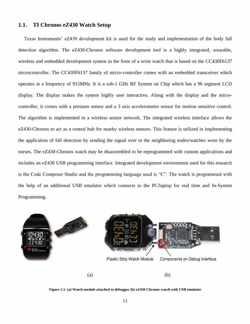
1.1. TI Chronos eZ430 Watch Setup
Texas Instruments’ eZ430 development kit is used for the study and implementation of the body fall
detection algorithm. The eZ430-Chronos software development tool is a highly integrated, wearable,
wireless and embedded development system in the form of a wrist watch that is based on the CC430F6137
microcontroller. The CC430F6137 family of micro-controller comes with an embedded transceiver which
operates at a frequency of 915MHz. It is a sub-1 GHz RF System on Chip which has a 96 segment LCD
display. The display makes the system highly user interactive. Along with the display and the micro-
controller, it comes with a pressure sensor and a 3 axis accelerometer sensor for motion sensitive control.
The algorithm is implemented in a wireless sensor network. The integrated wireless interface allows the
eZ430-Chronos to act as a central hub for nearby wireless sensors. This feature is utilized in implementing
the application of fall detection by sending the signal over to the neighboring nodes/watches worn by the
nurses. The eZ430-Chronos watch may be disassembled to be reprogrammed with custom applications and
includes an eZ430 USB programming interface. Integrated development environment used for this research
is the Code Composer Studio and the programming language used is “C”. The watch is programmed with
the help of an additional USB emulator which connects to the PC/laptop for real time and In-System
Programming.
(a) (b)
Figure 1.1: (a) Watch module attached to debugger (b) eZ430 Chronos watch with USB emulator
12
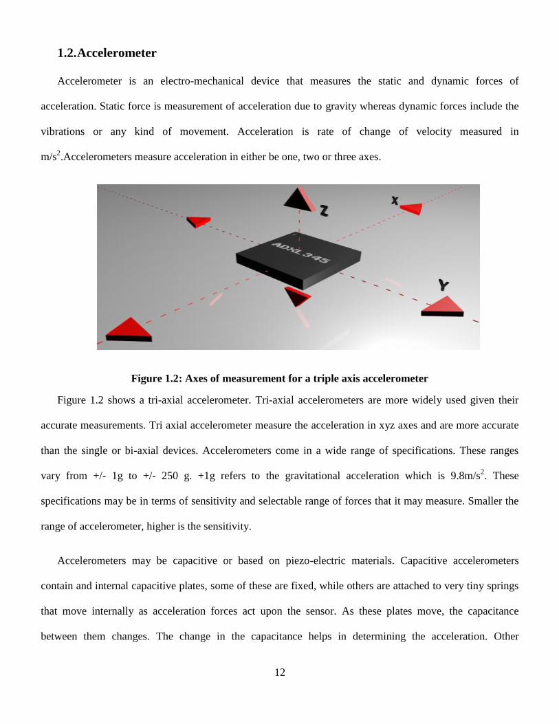
1.2. Accelerometer
Accelerometer is an electro-mechanical device that measures the static and dynamic forces of
acceleration. Static force is measurement of acceleration due to gravity whereas dynamic forces include the
vibrations or any kind of movement. Acceleration is rate of change of velocity measured in
m/s2.Accelerometers measure acceleration in either be one, two or three axes.
Figure 1.2: Axes of measurement for a triple axis accelerometer
Figure 1.2 shows a tri-axial accelerometer. Tri-axial accelerometers are more widely used given their
accurate measurements. Tri axial accelerometer measure the acceleration in xyz axes and are more accurate
than the single or bi-axial devices. Accelerometers come in a wide range of specifications. These ranges
vary from +/- 1g to +/- 250 g. +1g refers to the gravitational acceleration which is 9.8m/s2. These
specifications may be in terms of sensitivity and selectable range of forces that it may measure. Smaller the
range of accelerometer, higher is the sensitivity.
Accelerometers may be capacitive or based on piezo-electric materials. Capacitive accelerometers
contain and internal capacitive plates, some of these are fixed, while others are attached to very tiny springs
that move internally as acceleration forces act upon the sensor. As these plates move, the capacitance
between them changes. The change in the capacitance helps in determining the acceleration. Other

13
accelerometers can be centered on piezoelectric materials. They are basically used to measure dynamic
changes in any mechanical quantity. These tiny crystal structures output electrical charge when placed under
mechanical stress. The accelerometer used for this research is a BMA 250- capacitive tri-axial accelerometer
and the selected range is ±4g.
Accelerometers find their applications in the industrial field as the measure dynamic changes like
shock, acceleration and vibration. They are also used for gaming, medical monitoring, compass,
seismographs etc.
Figure 1.3: Accelerometer functions
1.3. Wireless Mesh Network
Wireless communication provides unprecedented freedom and mobility for a growing number of
devices. Wireless network eliminates laborious task of wiring as these devices need no wires to stay
connected. Wireless network facilitates easy, reliable and secure data transfer over long or short distance.
Mesh is a network topology where devices are inter-connected via many links to forward the traffic flow [3].

14
(a) (b)
©
Figure 1.4: (a) Wireless mesh network with source S and destination D (b) Wireless mesh network with intermediate nodes [3]
©Body area network
A Body Area Network is formally defined by IEEE 802.15 as, “a communication standard optimized
for low power devices and operation on, in or around the human body (but not limited to humans) to serve a
variety of applications including medical, consumer electronics / personal entertainment and other” [4].
Novel technology enhancements, constant miniaturization of sensor devices and wide applications of
wireless network has made Wireless Body Area Network (WBAN) very popular in the field of healthcare.
In WBANs, sensors are used to measure and/or monitor various human activities such as heart beat, body
movement, temperature, etc by placing them on the body of the patient or by implanting them [5].

15
Figure 1.5: Data rate Vs. Power for BANs [4]
Figure 1.5 shows a graph between the power consumption and data rates for Body Area Networks. It
is seen that BAN occupies majority of the graph as compared to other protocols such as Zigbee, Bluetooth
and wireless USB. It can also be seen that BAN accounts for the lowest power consumption in spite of
having a larger range of data rates. Therefore, most of the medical applications use BANs for its ultra low
power consumption, ease of data transfer and higher data rate.
Distance 2 meter – Standard
Network Density 2-4 nets/m2
Network Size Maximum: 100 devices/ network
Power consumption 1mW/Mbps
Startup time <100uS
Latency (end to end) 10mS
Network Setup time <1 sec
Table 1 BAN specification [4]

16
Table 1 shows basic features of a Body Area Network. BANs have higher bandwidth, more
scalability, less start up time and good coverage in terms of range of communication.
1.3.1. Wireless Sensor Network
A multi hop network in which stationery routers relay traffic on behalf of other routers or client station
wirelessly is known as a Wireless Mesh Network (WMN) [6]. Mesh is a network topology where devices
are connected via many links and select the optimal path to forward traffic [7]. In a sensor network, data
collection is related to the connectivity between the sensor nodes and the coverage. In this research, data is
collected from the sensor nodes and forwarded to the receiving node which may be thought of as the base
station. Relaying data to the data sink is uniform in nature and relieves other sensor nodes from getting
overburdened with data. The type of communication in the network is simplex and only one way. The
receiver nodes receive the data but will not transmit and vice versa.
Lifetime is the most critical issue for sensor networks as most of them work on battery powered nodes
and energy consumption is extremely high. However, researchers suggest that energy consumption could be
reduced by considering the interdependencies between individual layers in the network protocol stack. Also,
using a low power model for transmission and forwarding the packets will help mitigate power losses, lower
energy consumption and improve the lifetime of the network. Sensor networks are found to interest most of
the monitoring fields like surveillance, warfare, medical applications, micro-surgery and environmental
monitoring [8]
1.4. Zigbee
In a wireless sensor network, the communication method varies depending on the application either at
the medical, industrial or scientific. One of the most widely used communication protocols is the ZigBee
protocol, which is a technology composed of a set of specifications designed for wireless sensor networks.
This system is characterized by the conditional type of communication, its mean, which not 20 require a

17
high volume of information (just over a few kilobits per second) and also have a limited walking distance.
ZigBee, also known as IEEE 802.15.4, can operate at three different frequency bands. Freescale module
presented in section 3.5 uses the Zigbee protocol for data transfer and to communicate with the controller
unit. ZigBee is a low-cost, low-power, wireless mesh network standard. Zigbee is widely deployed in
wireless control and monitoring applications due to its low cost. The Ultra low power feature not only
allows longer battery life but also improves the reliability and the range.
Figure 1.6: Zigbee protocol stack [9]
For sensor network applications, key design requirements revolve around long battery life, low cost,
small footprint, and mesh networking to support communication between large numbers of devices in an
interoperable and multi-application environment. ZigBee is targeted at applications that require a low data
rate and long battery life. ZigBee has a data rate of 250 Kbit/s, which is best suited for periodic or
intermittent data transmission from a sensor or input device. The technology defined by the ZigBee
specification is intended to be simpler and less expensive than other WPANs, such as Bluetooth [9].

18
1.5. Fall Detection
Fall is one of the most serious causes of fatal injuries amongst the elderly population. Most of the
prevalent fall detection systems fail to distinguish between Activities of Daily Life (ADL) and a real fall. In
this research, the system developed successfully identifies a genuine fall and also distinguishes it from fall
like activities like sudden movement. Texas Instrument’s eZ430 Chronos embedded watch system with a
built-in accelerometer. Primary objective of this research is to reduce the mortality rate occurring due to
elderly falls and to promote independent living.
Parameters such as acceleration, angle of orientation, angle of tilt and reference points in 3D co-
ordinate space has been considered. Threshold limits have been set for all these parameters, crossing of
which will result in setting of an alarm. Following sections present a detailed approach and explanation with
regards to the design of the algorithm, statistical analysis and the implementation.
Figure 1.7: Block diagram of fall detection system
19
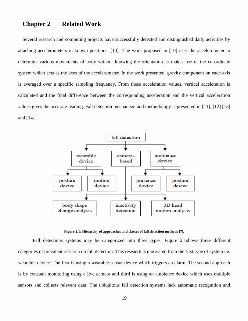
Chapter 2 Related Work
Several research and computing projects have successfully detected and distinguished daily activities by
attaching accelerometers in known positions. [10] The work proposed in [10] uses the accelerometer to
determine various movements of body without knowing the orientation. It makes use of the co-ordinate
system which acts as the axes of the accelerometer. In the work presented, gravity component on each axis
is averaged over a specific sampling frequency. From these acceleration values, vertical acceleration is
calculated and the final difference between the corresponding acceleration and the vertical acceleration
values gives the accurate reading. Fall detection mechanism and methodology is presented in [11], [12] [13]
and [14].
Figure 2.1: Hierarchy of approaches and classes of fall detection methods [7].
Fall detections systems may be categorized into three types. Figure 2.1shows three different
categories of prevalent research on fall detection. This research is motivated from the first type of system i.e.
wearable device. The first is using a wearable sensor device which triggers an alarm. The second approach
is by constant monitoring using a live camera and third is using an ambience device which uses multiple
sensors and collects relevant data. The ubiquitous fall detection systems lack automatic recognition and

20
hence, the patient is left in fallen state until help reaches him. The present systems also make use of
accelerometer sensors for motion detection. Many devices also take into consideration the altitude along
with the change in acceleration for accuracy. Bluetooth and Zigbee is a common mode of communication
for thesis devices.
The research presented in D. Chen et al. [1] uses a micro-controller circuitry and a data-logger for
collecting and processing the data. The processed data is sent over to the monitoring centre through Zigbee
gateway and detects if a fall has occurred or not. Similar model was showcased A. Sorvala in [15]. The team
made use of a gyroscope along with accelerometer sensor to set two threshold limits for detecting fall. This
led to higher accuracy as the gyroscope used also measured the angular velocity and angle of tilt. M Silva
and et al [16] used mobile with in-built accelerometer and developed and Android based application to
monitor human motion and detect body fall. The application was programmed to calculate the time lapse
between the “pre-fall” position and the “free-fall” or “real fall” positions. If the time difference and the
change in acceleration due to gravity were found to be higher than the set threshold, an email or message
would be sent to the pre-defined contact saved in the mobile device. A. Bourke and et all in [13] used the
Bluetooth technology to send the fall signal from the device to the emergency contact. The algorithm is not
implemented in wireless network but the waist mounted embedded fall detection device transmits data to the
nearest Bluetooth device on one-on-one basis. They have also presented the change in values for different
daily life activities and compared it with the real fall.

21
Chapter 3 Methodology and Algorithm Design
In order to successfully implement the fall detection algorithm, it first important to differentiate and
understand the basic difference between a real fall and fall-like activities. Fall-like activities are regular
activities that a person does in everyday life like walking, jogging, standing quickly, lying down, jumping
etc. All these activities are similar to fall except that the change in acceleration is not same. The daily life
activities are tested and different parameters like acceleration due to gravity, change in the co-ordinates in
three axis, angle of orientation and angle of tilt are measured and analyzed. All these parameters are then
compared with that of the real fall to correctly define a fall signal. Analysis and calculations presented in the
sections below clearly show that the difference in change of acceleration for regular activities is extremely
small as compared to that of a real fall. The most significant parameter is the change of acceleration in the Z
axis. It is observed that whenever the watch is dropped in the vertical direction, maximum change occurs in
the acceleration in the z axis. Therefore, the change in the Az component of acceleration is the highest.
Setting a threshold limit on Az and the total acceleration led to the precise calculation of the fall signal. The
algorithm for body fall detection takes into account the values obtained from the accelerometer and the
changes in the co-ordinate axes. The tri-axial accelerometer in the watch measures the acceleration due to
gravity in the x, y and z axes. The single axis change in acceleration (Az) works significantly in determining
a real fall. The formula mentioned below makes use of this phenomenon to distinguish between a genuine
body fall and ADL. The data obtained from the accelerometer is processed at real time to avoid time lapses.
Different ADL and body fall scenarios have been studied and identified to characterize and specify
differences between them. It not only helps in developing a new algorithm but also helps in improving
existing designs. 6 different ADL are characterized depending on the body movement. Similarly 4 different
fall positions are considered. The characteristics are mentioned below:

22
1. Forward fall: Ends up lying in a flat position. The body position remains lateral to ground if fell on
knees and unable to recover. Time of fall may last from 1 to 2 seconds.
2. Backward fall: Most severe type of fall. Body position remains lateral. Change in acceleration is
maximum and may cause serious head injury. Fall time may be 1 to 2 seconds
3. Fall to the left: Higher probability of recovering from the fall. Higher chances of triggering a false
alarm due to orientation change.
4. Fall to the right: Higher probability of recovering from the fall. Higher chances of triggering a false
alarm due to orientation change.
5. Fall from bed: Fall altitude is less. Injury may depend if the person fell on ground or mattress.
6. Fall from a chair: Fall height is slightly higher. Time of fall varies from 1 to 2 seconds.
3.1. Approach
The fully reprogrammable development kit is based on the CC430F6137. The CC430 is an MSP430 that
has an integrated <1GHz wireless transceiver for custom wireless applications. Along with the
accelerometer, a pressure sensor, temperature sensor and voltage battery monitor is also embedded in the
watch. The watch has a 96 segment LCD display drive directly by the CC430. Integrated development
environment used for this research is the Code Composer Studio and the programming language used is
“C”. The watch is programmed with the help of an additional USB emulator which connects to the
PC/laptop for real time and In-System Programming. After the watch is programmed, the side buttons on the
watch are used for navigating through the menu and selecting the desired option from it. The Menu consists
of 5 options:
i) Idle: This is similar to reset condition. If the watch is not transmitting or receiving any data, it stays in
the idle state. Power consumption of the watch in “idle” mode is the least. Also, after successful fall
detection, the watch needs to be brought out of the radio mode and set to idle mode again.

23
ii) Node Address: This option allows the user to set patient’s node to a unique single digit node address.
Each node number represents the patient. The network can have maximum up to 9 patients with their
watch ready to transmit fall signal. On discovering a fall, this node address is displayed on the receiver
node worn by the nurse.
iii) Transmit start: The patient’s watch needs to be in “transmit” mode for fall to be detected. This mode
activates the radio module of the watch and also activates the accelerometer. Power consumption is the
highest as the accelerometer and radio device both are functioning together.
iv) View node: “View node” menu option is for the nurse’s watch. The selected node number is
continuously monitored for fall. The watch is capable of monitoring multiple nodes and detects more
than one fall.
v) Battery Voltage: Shows the battery life and notifies if the battery needs to be replaced. The voltage of a
new battery is 3V and may function up to when it reaches 1.2 V.
Figure 3.1: eZ chronos watch block diagram

24
Figure 3.1 shows the basic block diagram of the Chronos watch module. It shows a micro-controller
unit which acts as the driving block for the Display, buzzer, antenna and the acceleration sensor or acceloro-
meter. In this research due to the simultaneous operation of the display, antenna and the acceleration sensor,
the buzzer cannot be triggered due to the very high energy consumption by the antenna in the radio mode.
Figure 3.2: Chronos watch in transmit and receive mode
Figure 3.2 shows basic diagram of the implemented algorithm. It can be seen that the watch in the
center is transmitting data to the other watches which are receiving the data. The transmitting node
represents the patient whereas the receiving nodes are the nurses or any hospital staff. The actual
implemented design may have up to 9 transmitting nodes. The number of receiving nodes may vary from 5
to 9. A single receiver node is capable of monitoring all 9 transmitter sensors but to avoid over burdening,
the number of receiver nodes are considered to be half of transmitter nodes. As mentioned earlier,
communication and information relaying throughout the network follows simplex type of communication.
Five student volunteers wore the watch to test the correctness of the algorithm and observe different
patterns of daily activities and falls. The watch worn by the patient is set to single digit number i.e. node
number and no two watch can have the same node number. All these watches are always set in the
“transmit” mode with an accelerometer in active state. The accelerometer keeps collecting data at real time

25
until a real fall is detected. The watches worn by the hospital authorities or nurses are in the
“monitor/receive” mode. If a patient falls, an alert signal is broadcasted across the wireless nodes. This
signal reaches all the neighboring sensor nodes which are constantly in the “monitor” mode. The display of
the watches shows the node number of the patient who fell and needs assistance. Once the authority reaches
the patient, the transmission is stopped manually using the reset button present on the watch. The signal
reaches the nurse watches via intermediate watches in minimum number of hops. The intermediate watches
may not be worn and be used only for the purpose of increasing the radius of the network. The range of the
signal may be further extended by introducing additional watches in the path. This embedded system adds
excellent features to the ubiquitous devices in heath care. The features are:
i. Distinguishes between real fall and daily life activities like jumping or sudden jolt.
ii. Reliable and protected transmission of signal in wireless network when a real fall is detected.
iii. Hands free device which automatically alarms the authority on the detection of fall. It does not
require the patient to activate the device on falling.
iv. The algorithm is secure in nature as no other device may intercept the radio transmission or disturb it
in any way.
v. The algorithm is highly reliable as most of the significant parameters such as co-ordinates reference
points, acceleration, angle of orientation and Tilt angle has been considered
3.2. Fall Detection Algorithm
The in-built accelerometer plays the most significant role in the accomplishment of the body fall
detection algorithm. The entire algorithm revolves around the readings measured by the accelerometer and
the threshold values. Accelerometer is a motion sensitive electro-mechanical device which measures the
acceleration due to gravity. The algorithm follows the following 2 important steps:

26
1) Calculation of the acceleration values in x, y and z co-ordinate axes, calculating the overall acceleration
value and comparing it with the threshold value.
2) If the value of the calculated acceleration is found to be greater than the threshold value, fall flag is
raised and alert signal transmitted across the wireless network, if not, the accelerometer continues its
normal mode of operation until a genuine fall is detected.
Figure 3.3 fall detection system [15]
Figure 3.3 shows a fall detection system which follows almost similar approach as presented in this
thesis. The system uses wireless communication for data transmission, not in a mesh network. The Inertial
Measurement Unit (IMU) consists of an acceleration sensor and a gyroscope for estimating the impact of
fall. TI chromos module is used for determining the posture after the fall. The Impact of the fall can be
determined by computing the total change in acceleration force with respect to Earth’s gravitational pull.
Similarly, posture determination is done by calculating the angle of orientation.

27
3.3. Statistical Analysis
To consider the acceleration uniformly, data change the three axes can be taken, which is the magnitude
of acceleration in three-dimensional space when the three acceleration values are for the same point in time.
The TI Chronos circuitry processes these samples sequentially but fast enough to estimate the total change
in acceleration. The value is calculated at the rate that the accelerometers are sampled and when it exceeds a
threshold then it is safe to say that a fall has occurred. The threshold can be set based on the results obtained
from fall and non-fall activities. The lowest change in acceleration measured for fall is about three times
“g”. It is also confirmed that the acceleration does not exceed 3g for daily activities. However, for a rigorous
movement or sudden jolt, the value may rise and equal 3g. Due to the overlap of ranges for fall-like and fall
scenarios, it is extremely important to set another threshold limit to validate and correctly detect fall. The
following formulas give an exact idea about the implementation of the fall detection algorithm.
Atotal = 3.1
ωTot = 3.2
In equation 3.1, Atotal is the total sum vector magnitude for the 3-D acceleration data and ωTot is the
angular movement where Ax, Ay, and Az denote accelerations whereas ωx, ωy and ωz is the angular velocity
along x, y and z-axis [1]. The threshold value is set using Eg. Atotal =
3.1, if the acceleration was more than 3g in the z axis, fall flag would be raised to alert the
authorities. Also if 2 > , severe category fall is detected. The comparison with the
acceleration in the Az component is used as a second threshold.
In the absence of actual acceleration with respect to the ground, the accelerometers detect the normal
force of gravity, 1 G, directed upward from the ground [15] . This force is always present and is a static
component in the acceleration data. Whenever the patient is in stationery position, the force is equivalent to
1g and reflects the normal force. When a person falls, he or she undergoes a large change in position from
28
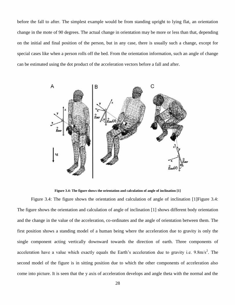
before the fall to after. The simplest example would be from standing upright to lying flat, an orientation
change in the mote of 90 degrees. The actual change in orientation may be more or less than that, depending
on the initial and final position of the person, but in any case, there is usually such a change, except for
special cases like when a person rolls off the bed. From the orientation information, such an angle of change
can be estimated using the dot product of the acceleration vectors before a fall and after.
Figure 3.4: The figure shows the orientation and calculation of angle of inclination [1]
Figure 3.4: The figure shows the orientation and calculation of angle of inclination [1]Figure 3.4:
The figure shows the orientation and calculation of angle of inclination [1] shows different body orientation
and the change in the value of the acceleration, co-ordinates and the angle of orientation between them. The
first position shows a standing model of a human being where the acceleration due to gravity is only the
single component acting vertically downward towards the direction of earth. Three components of
acceleration have a value which exactly equals the Earth’s acceleration due to gravity i.e. 9.8m/s2. The
second model of the figure is in sitting position due to which the other components of acceleration also
come into picture. It is seen that the y axis of acceleration develops and angle theta with the normal and the

29
z axis. The angle also brings tilt angle into calculation which aids in achieving accuracy. The third model
shows a different human movement where the angle is formed between the y axes. These angle formation
and analysis of angle of tilt is performed for daily activities to differentiate their characteristic results from a
genuine fall. The values obtained from the daily activities and that of fall vary in very high magnitude as fall
happens with greater force, impact and the change in the angle formation along with the tilt is very sudden.
However, for some fall-like activities, also have certain characteristics which are exactly same as that of a
genuine fall. It can lead to give incorrect results and set off a false alarm if a sudden activity is wrongly
identified as a fall. So as to avoid false triggering of alarm, the data is processed and analyzed for its
acceleration and change in angle of orientation along with co-ordinates. Body movement or activity may be
categorized as ADL if the differences between the analyzed values are small; else they are categorized as
fall.
The second aspect of the algorithm is the determination of the angle of tilt or tilt angle and angle of
orientation. The measurement of angle of orientation is an essential component in determining a fall. It helps
in determining the exact position of the patient before fall and also how severe or amenable the fall was. The
angle of orientation is calculated as follows:
Θorientation = 3.3
Where Ax, Ay, Az are the accelerometer values in 3D space co-ordinates [17]. The Tilt Angle TA describes
the body’s posture, when the body is static. Its value was defined as indicated in Eq 3.4, 3.5, 3.6 below:
TAx =
3.4
TAy =
3.5
TAz =
3.6
Where G is gravity acceleration (=1g). As the sensor position of a standing user, the value of TAx, TAy, and
TAz are 90°, 90°, and 0°, respectively [11].
30
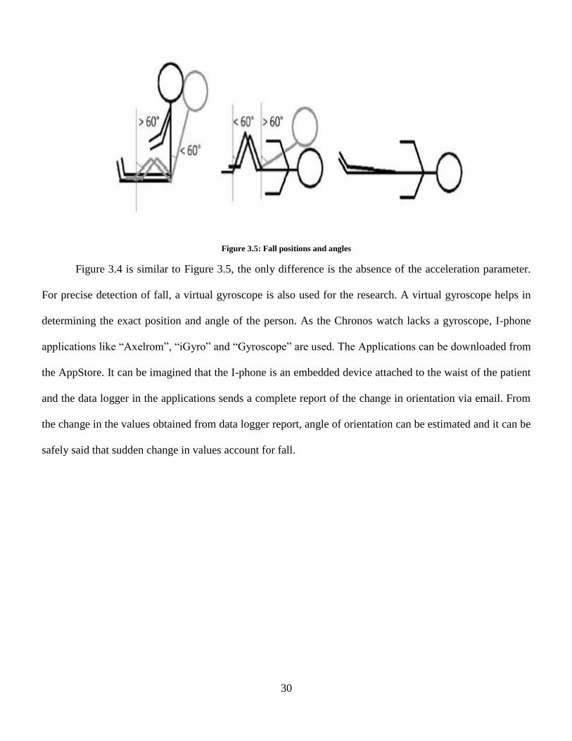
Figure 3.5: Fall positions and angles
Figure 3.4 is similar to Figure 3.5, the only difference is the absence of the acceleration parameter.
For precise detection of fall, a virtual gyroscope is also used for the research. A virtual gyroscope helps in
determining the exact position and angle of the person. As the Chronos watch lacks a gyroscope, I-phone
applications like “Axelrom”, “iGyro” and “Gyroscope” are used. The Applications can be downloaded from
the AppStore. It can be imagined that the I-phone is an embedded device attached to the waist of the patient
and the data logger in the applications sends a complete report of the change in orientation via email. From
the change in the values obtained from data logger report, angle of orientation can be estimated and it can be
safely said that sudden change in values account for fall.

31
Figure 3.6: I Phone app "data logger “showing acceleration value at different sampling frequency
Figure 3.6 shows the I phone applications used for the purpose of finding acceleration and the angle
of orientation. The sampling frequency is varied from 27Hz to 16Hz depending on the position of the
person. It can be see that at some time interval the change in acceleration is extremely abrupt and higher
than the normal, this account for body fall. Sudden change in Z axes of the acceleration component when the
sampling frequency is higher confirms the fall. If the acceleration changes are very high but the change in
Az is not more than the set threshold, the activity is normal human movement.
This algorithm extracts features of falls by wireless communication by discriminating between
genuine falls and ADL events. The change in acceleration describes the activity level of the body, which
contains both the dynamic acceleration and the gravity acceleration.
The following algorithm was used as reference and modified for accuracy, correctness and scalability:
i. If |αAmax-αAmin| < 0.4g | and |ωAmax – ωAmin| < 60˚/s| then
ii. Recognize the presence of static posture

32
iii. Determine the transition before the present lying posture is intentional
iv. If αAmax-αAmin > αthreshold, detect a fall then return yes
Else return No. [18]
It is modified accordingly to co-ordinate reference system, acceleration, tilt angle and angle of
orientation. A threshold value for the acceleration is set for standing and lying body positions. The device
needs to be set in the particular mode to monitor the change in threshold values of acceleration due to
gravity, orientation or co-ordinates. A fall is detected when acceleration due to gravity changes by thrice the
actual acceleration.
The time between the changes in the values of the parameters to be measured also plays in detecting
a fall and differentiating it from ADL. Generally, a fall lasts for 1-2 seconds. So the difference in the values
at the start and a few seconds after the fall determines if a fall has been detected or not. However, in this
research, the time has not been considered as the data is processed at real time and a buffer for keeping the
time count is not used. For reliable operation of the fall detection system, genuine fall events should not be
missed while sudden body activity and jerks should be minimized. This is taken care by the algorithm as the
magnitudes of acceleration in falling are generally greater than those in normal activity [19]. Setting
thresholds for each of the three axes of measurement does not work well, because it does not cover all the
possible directions of impact in a uniform way. [20] To consider the acceleration uniformly, the norm of the
three axes can be taken, which is the magnitude of acceleration in three-dimensional space when the three
acceleration values are for the same point in time.

33
Figure 3.7: Fall detection algorithm

34
3.4. Working
Figure 3.8: (a) Patient Watch in "Safe" mode (b) Nurse’s watch waiting for the data
Figure 3.8a shows “safe” mode on the display of the watch. This watch is worn by the patient and is
programmed to be node one. Since it is meant to detect fall signals it is always in the transmit mode. When
the patient is in a stationery position or when fall has not occurred the watch will always display “Safe”.
Figure 3.8b shows the watch of the nurse. This watch is used for the purpose of monitoring transmitter
nodes and waiting for fall signal. Therefore, the watch displays “Data Wait”. As long as the patient remains
in stationery position and doesn’t fall, the watch will continue to wait for the data.
At this time, the display, the accelerometer and the antenna are the active components of the watch.
It is made sure that other features are turned off to save battery power. The power consumed in the radio
Transmission and reception mode is highest and may drain the battery.

35
Figure 3.9: Fall signal on the patient's watch -programmed as node 1, Data being received on the display of nurse watch showing node 1.
After a patient falls, the display on the watch changes from “safe” to “fall”. This is shown in Figure 3.9.
This signal is immediately transmitted to the nearest receptor node. Thus, the display on the receiver
watches changes from “data wait” to “data rx 01” 01 is the node number representing the fallen patient. This
helps in identifying the fallen patient and sending him timely help. After the nurse reaches the patient who
fell, his/ her watch must be turned off or set to idle mode to stop transmission and avoid the signal to reach
other receiver nodes. Setting the watch in idle state also saves the battery and energy consumption.
Sometimes, a rigorous activity may also trigger a false alarm. This happens due to the overlapping
ranges of acceleration. In case of a false alarm, the patient can stop the transmission and set the watch again
into safe mode. Also, a fall signal may not be detected sometimes. In this case too, the patient has the option
of manually setting alerting the authority to notify that he/ she fell. To avoid the false triggering, a buffer
period of 1 to 2 seconds is required for the accelerometer to come back to its normal functioning after
recovering from a sudden shock or a jolt.

36
3.5. Extended Research
Along with Texas Instruments’ Chronos Module, Freescale Zstar3 device and FRDM board may also
be used for fall detection. Having studied both the modules, the fall detection algorithm will be easier to
implement in the Zstar3 module but programming it would become extremely difficult. The Zstar3
module comes with a tri-axial accelerometer sensor, 8bit micro-controller, 2.4GHZ transceiver and uses
Zigbee protocol for communication purpose.
Figure 3.10: Freescale's Zstar 3 device
Zstar3 module is capable of having 16 nodes sensors in a star topology with a single base station
controller unit. The controller unit is the computer running the Freescale application which monitors all the
16 nodes for fall detection. It offers flexibility to change the sampling frequency. Like the TI Chronos
watch, even Zstar3 requires a 3V battery for operation. The range of communication ranges from 2m. Along
with fall detection, it also has ability to detect taps and recognize gestures.

37
Figure 3.11: Freescale's FRDM board
Freescale’s FRDM board consists of an 8 bit ARM Cortex micro-controller which has made it
widely popular. It comes with a tri-color LED, tri0axial accelerometer and 16 I/O pins for further extension
and development. A capacitive touch slider adds the feature of touch and tap recognition. Open SDA debug
interface eases programming. External boards such Mbed or Arduino shield needs to be interfaced with the
board for establishing wireless communication. Interfacing the board with a wireless USB device may solve
the problem but may give rise to power issues. FRDM board is ultra low power and low cost development
board. Successful implementation of the algorithm on it will not only save power but also reduce cost and
introduce a very sophisticated product in market.

38
Chapter 4 Energy and Power Analysis
TI Chronos eZ430 development kit is a low power SoC. In the CPU active mode, the current
consumption is 160uA/MHz In the radio RF reception/transmission mode at a frequency of 915MHz, the
figure goes upto 15mA at a data rate of 250kbps.
The kit uses a Lithium battery of 3Volt for functioning. The estimated battery life for continuous
acceleration measurement is one and a half months with average current of 166 uA. When in transmission
mode, the battery life reduces to 2 days with current of 3.7 mA. Due to the very high current consumption
during the transmission and reception of RF signals, the buzzer of the watch cannot be made to function on
reception of the alert signal. This drains the battery completely and the display of the watch goes blank.
Therefore, the watch needs frequent human monitoring.
Power= Current * Voltage 4.7
Figure 4.1: Current versus frequency values for the micro-controller in the watch
39
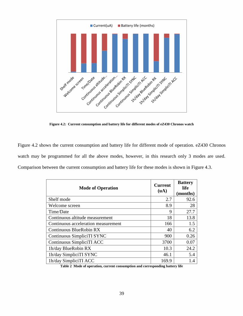
Figure 4.2: Current consumption and battery life for different modes of eZ430 Chronos watch
Figure 4.2 shows the current consumption and battery life for different mode of operation. eZ430 Chronos
watch may be programmed for all the above modes, however, in this research only 3 modes are used.
Comparison between the current consumption and battery life for these modes is shown in Figure 4.3.
Mode of Operation Current
(uA)
Battery
life
(months)
Shelf mode 2.7 92.6
Welcome screen 8.9 28
Time/Date 9 27.7
Continuous altitude measurement 18 13.8
Continuous acceleration measurement 166 1.5
Continuous BlueRobin RX 40 6.2
Continuous SimpliciTI SYNC 900 0.26
Continuous SimpliciTI ACC 3700 0.07
1h/day BlueRobin RX 10.3 24.2
1h/day SimpliciTI SYNC 46.1 5.4
1h/day SimpliciTI ACC 169.9 1.4 Table 2 Mode of operation, current consumption and corresponding battery life
Current(uA) Battery life (months)

40
Figure 4.3: Current consumption and battery life for 3 modes in the programmed watch
Mode of
operation Current (uA)
Battery Life
(months)
Acceleration 166 1.5
Radio mode 3700 0.07
Idle 2.7 92.6 Table 3: Mode of operation and corresponding current consumption and battery life for programmed watches
Table 3. shows the battery life and current consumption for the modes of operation implemented in this
research. The watch is programmed only to function in the above three modes to save energy. Radio mode
has the highest energy consumption due transmission and reception of data at a very high frequency of
915MHz. Along with the transmission; the watch module has an active accelerometer and a functional
display which add to the current consumption. All these factors account for a shorter battery life and faster
energy drain. The least energy consuming mode is the “idle” mode where the accelerometer and the antenna
are disabled. Overall energy consumption also increases if the number of intermediate nodes increases
between the paths from source to destination.
Acceleration Radio mode
Idle
166
3700
2.7
1.5 0.07
92.6
Current consumption and battery life
current consumption(uA) Battery life(months)
41
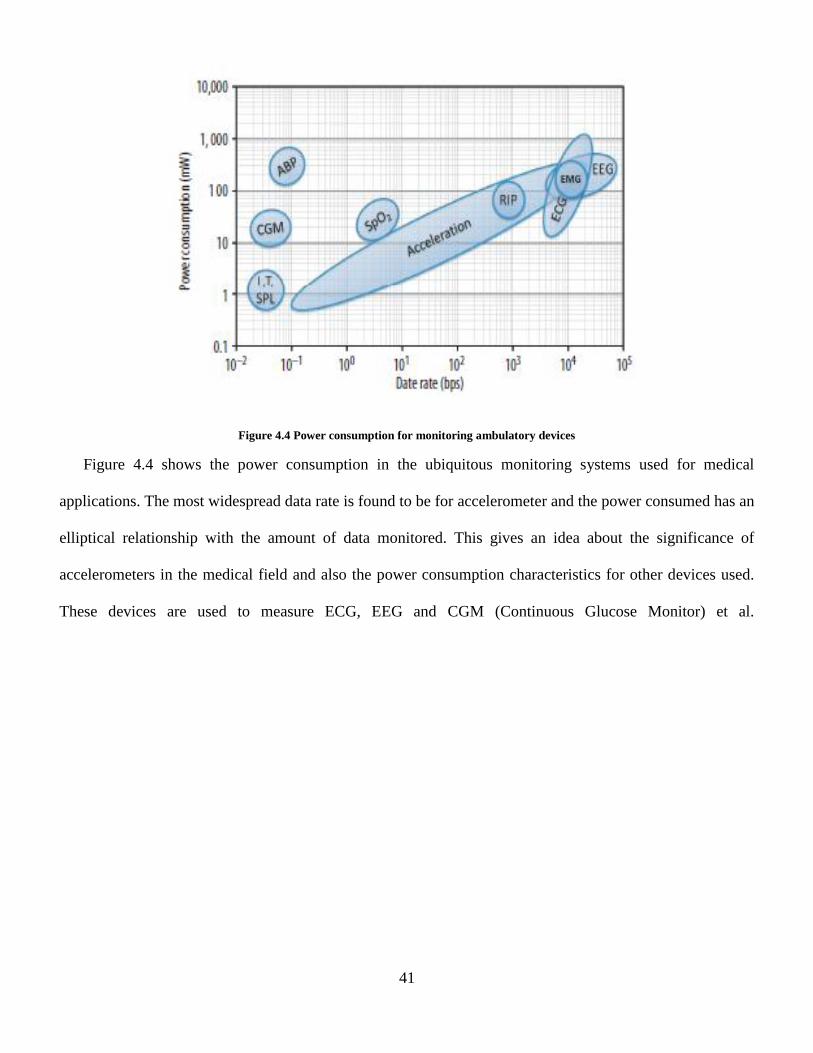
Figure 4.4 Power consumption for monitoring ambulatory devices
Figure 4.4 shows the power consumption in the ubiquitous monitoring systems used for medical
applications. The most widespread data rate is found to be for accelerometer and the power consumed has an
elliptical relationship with the amount of data monitored. This gives an idea about the significance of
accelerometers in the medical field and also the power consumption characteristics for other devices used.
These devices are used to measure ECG, EEG and CGM (Continuous Glucose Monitor) et al.

42
Chapter 5 Results
The entire setup is capable of monitoring up to 9 sensors simultaneously. The number of patient nodes may be
increased if required. This helps in forming a mesh network. Other factors like tilt, tap and free fall may also be
measured using the accelerometer, sensor and the transceiver module. The sensor measures the x, y, and z co-
ordinates and measures the change in acceleration due to gravity. The device software tool is also capable of
plotting the change in co-ordinates on a scope window.
5.1. Acceleration
(a) (b)
Figure 5.1: (a)Changes in acceleration values for ADL and fall positions (b) Total acceleration for fall positions and ADL
As mentioned earlier, acceleration plays the most important role in determining and distinguishing between a real
fall and fall like activity. The graph above shows the difference in the acceleration values in 3 axes for fall and
different ADL. Different positions and directions have been considered for fall. It is clearly seen that the bars on
the left which represent fall activities are taller than the bars for fall like activities.
-3
-2
-1
0
1
2
3
Rig
ht
Fall
Left
Fal
l
Forw
ard
fal
l
Bac
kwar
d f
all
Sitt
ing
Up
righ
t
Lyin
g o
n t
he
bed
Stan
din
g
AD
L 1
AD
L 2
AD
L 3
AD
L 4
Ax
Ay
Az
0 0.5
1 1.5
2 2.5
3 3.5
4 4.5
Rig
ht
Fall
Left
Fal
l
Forw
ard
fal
l
Bac
kwar
d f
all
Sitt
ing …
Lyin
g o
n …
Stan
din
g
AD
L 1
AD
L 2
AD
L 3
AD
L 4
Total acceleration
Total acceleration

43
Body Position/fall Total value of
Acceleration-“g”times (m/s2)
Right Fall 3.071657433
Left Fall 3.307628141
Forward fall 3.44573145
Backward fall 3.705086457
Sitting Upright 0.971802449
Lying on the bed 1.03024269
Standing 0.974525526
ADL 1 0.908295106
ADL 2 1.012916581
ADL 3 1.004241007
ADL 4 1.007720199
Table 4: Total acceleration for different fall position and ADL
Table 4 estimates the total acceleration due to gravity for different fall scenarios and activities of daily life. It
can be observed that the values of acceleration are extremely high for all the fall scenarios as compared to normal
activities. The values are found to be three times the actual gravitational pull whereas, for routine activities the
acceleration remains around the 1 g limit. For all ADL, the “g” value revolves around its real value because there
is no sudden change either in the angle of bending or acceleration components in the x, y and z axes. It can also be
seen that the highest range of “g” is four times its original value. This is the most critical and severe case of fall i.e.
Backward fall. The analysis and approximations in the above table makes it easy to understand the difference in a
fall and a fall-like activity in terms of mathematical calculations.

44
5.2. Angle of Orientation and Angle of Tilt
Figure 5.2: Angle of tilt in different axes for fall positions and ADL
Above graph gives the total acceleration for body fall and ADL. It is observed that the acceleration values
for fall, especially backward fall is higher than the daily activities. Figure 4.2 gives a comparison between the
position and the angle of tilt. It is observed that the angle of tilt is null for all the fall positions as the angle exceeds
the threshold, whereas for ADL the angle remains within the threshold value.
Activity Angle of Tilt for static bodies
X Y Z
Right Fall - - -
Left Fall - - -
Forward fall - - -
Backward fall - - -
Sitting Upright 99.20689622 151.642363 112.3336827
Lying on the bed 61.96570347 77.290967 27.12675312
Standing 92.86598398 163.739795 99.20689622
ADL 1 124.0557977 132.067065 104.4775122
ADL 2 99.20689622 91.145992 180
ADL 3 88.854008 95.1636071 0
ADL 4 96.31531557 122.005455 148.2116694 Table 5 Angle of Tilt for fall positions and ADL
0 20 40 60 80
100 120 140 160 180 200
Rig
ht
Fall
Left
Fal
l
Forw
ard
fal
l
Bac
kwar
d f
all
Sitt
ing
Up
righ
t
Lyin
g o
n t
he
bed
Stan
din
g
AD
L 1
AD
L 2
AD
L 3
AD
L 4
X axis tilt
y axis tilt
Z axis tilt
Angle of tilt Vs. Position
0
20
40
60
80
100
120
140
160
180
Angle of orientation Vs Position
Angle of orientation

45
Table 5 gives a comparative analysis between fall scenarios and ADL in terms of the angle of tilt. Angle of Tilt
cannot be measured for any of the falls as the change in angle is so rapid that the reference normal which forms an
angle with the acceleration normal may have more than one component together. This makes it extremely difficult
to analyze tilt angles for falls. Therefore the columns for the x, y and z components have been left blank. Tilt-angle
played a vital role in distinguishing static postures: lying, sitting and standing, as well as, the transitions between
these static postures. However, in order to have an accurate estimate for the tilt-angle from the tri-axial activity
acceleration-signals, accelerometer needs to be firmly attached to the human body. Loosely placing the sensor on
the human body could result in changes in sensor’s orientation while subjects perform a dynamic activity and,
thus, makes it very difficult to land on a correct estimate for the tilt-angle. Therefore, tilt-angle was excluded from
the feature-list in the case of accelerometer’s position and attachment free recognition. Consequently, the three
static postures: sitting, standing and lying, were combined into a single class called the resting-activity. Moreover,
transitions between different activities were also not included in this study.
5.3. Sensitivity and Specificity
The algorithm needed statistical analysis and result activity base on series of tests performed. There are 4
possible situations:
True positive (TP): a fall occurs and the device detects it.
False positive (FP): the device announces a fall, but it did not occur.
True negative (TN): a normal (no fall) movement is performed, the device does not declare a fall.
False Negative (FN): a fall occurs but the device does not detect it.
In [16], it was also proposed a classification and evaluation of fall detectors. Two criteria were proposed to
evaluate the response to these four situations. Sensitivity is the capacity to detect a fall, eq 5.1 and specificity is the
ability to detect only a fall, Eq. (5.2) [16]

46
Sensitivity =
5.1
Specificity =
5.2
Results show that the sensitivity of algorithm to distinguish between a real and false fall is 78% and
specificity was found to be 69.2%. The rate of detecting false alarms was higher when the person moved wrist
from higher to lower level with a free-fall like motion. Series of tests performed gave the following results in terms
of success and failure percentage.
Scenario
Wrist Waist/trunk
Success % Failure % Success % Failure %
Falls 81 17 89 11
Non-Falls 73 27 88 12
Table 5 Success and failure rate for fall detection.
5.4. Comparison with Present Algorithms
Implemented algorithm has several benefits over the ubiquitous algorithms in terms of design
approach, privacy protection, reliability, fall detection, its success rate and energy consumption. As
mentioned in [1]. Their experimental results show that the average accuracy rate for falls is around 95%.
As compared to the presented algorithm which has an accuracy of 81%. However, the algorithm uses a
one-to-one system i.e. every patient monitoring device is monitored by its corresponding terminal unlike
in the presented algorithm where a number of patients may be monitored using one single device.
Therefore, the scalability of algorithm is higher. Also seen in [2], [18] algorithm uses a truncated
multiplier to set the threshold limits. This makes the algorithm extremely complex in terms of
computations as it involves filtering data, multiplication and squaring. The complexity of the algorithm

47
designed and implemented in this research process the data at real time and the computations are quick
too. Although the accuracy of the design in [2] is near 100% which is better than the presented
algorithm. Also the power saved is higher as the system does not use battery powered monitoring
devices. It can be said the algorithm presented in this thesis is more reliable than other algorithm
mentioned above. Considering the change in reference co-ordinate points, calculating the Az component
of acceleration along with total acceleration makes it extremely valid and accurate. Not only does the
algorithm successfully differentiate between jolts, quick activities or sudden rigorous activity from a real
fall but also prevents false alarm triggering. The algorithm protects the privacy of the patient as there is
no video device employed for the algorithm implementation and detection of fall. It gives 100% privacy
to the person. The wrist watch makes it comfortable for the patient to wear the device as compared to
wear or implant it on waist. The following table gives the comparison results.
Parameters of
comparison Presented algorithm
Compared algorithm 1
[21] Compared algorithm 2
[22]
Position of the
device Wrist Waist Chest
Privacy Total privacy protection, video
devices not employed
Privacy invaded due to
presence of video
monitoring cameras
Privacy remains intact
Threshold
parameter
Change in reference co-ordinates,
total acceleration, change of
acceleration in Z axes, Angle of tilt
Change in human posture Change in acceleration
Method of
communication Wireless transmission at 915MHz
Data transferred to
computer from wired
camera module
Bluetooth
Alarm
triggering Automatic alarm triggering
Automatic alarm triggering
absent
Automatic alarm
triggering absent
Reliability
Extremely reliable, avoids false
triggering, differentiates between
fall and fall-like activities, more
reliable due to multiple thresholds
No differentiation between
ADL and real fall. Less
reliable
Side falls not detected,
differentiates between
ADL and fall
Power 100uW-1mW Not considered Not considered
Accuracy 81% 90% 96%
Range of
communication 2-5 meters
Depends on lens’ focal
length 2 meters
Table 6 Comparison with other designs

48
Table 6 shows the comparison of the presented algorithm with other 2 designs. It can be seen that the
implemented algorithm considers 2 threshold limits which makes it extremely reliable. The use of
Chronos watch makes it very comfortable to wear. Also, alarm triggering is automatic which works well
if the fallen patient goes in to and unconscious state. The algorithm takes in into account the energy and
power consumption and makes efforts to mitigate the losses. Power analysis has not been presented by
the compared algorithms. The fall detection mechanism makes sure to guard the privacy of the patient
by not employing video devices for monitoring. The communication between the watches is secure i.e it
prevents interception from other wireless devices and avoids false alarm triggering.

49
Chapter 6 Conclusion and Future Improvements
This research aimed at developing a portable, compact and a wearable device for detecting human falls.
The research has achieved its specified goal of differentiating between fall and non fall gestures and the
setup successfully detects body fall. The wireless sensor networks helps in adding the feature of automatic,
hand free assistance calling. It is also observed that the algorithm is 81% efficient when the watch is worn
on the wrist. However, if the SoC is placed on waist or trunk of the patient, the efficiency increases to 89%.
Since the TI Chronos kit is low power SoC, it consumes very little power and has an option of setting the
watch in idle mode to save power.
Process flow of detection algorithm designed, it is small-size and more comfortable. The data is
processed at real time and data processing is performed using micro-controller circuitry. Each sensor node
processes the data and therefore, the fall-detection terminal is capable for independent work, and detects
falls timely. The algorithm of fall detection is low-complexity and effective. The posture detection included
most ADL events, except lying down in horizontal. Some falls were undetected, because of the factors of
range overlap and buffer time for accelerometer restart. The experiments were not performed on the elderly
and hence results may vary from the ones that are presented here. All tests were taken by young volunteers
and fall were performed on mattress and not ground to ensure the safety of the volunteers. Through analysis
of the kinetics characteristics of fall events, an effective method using a tri-axes accelerometer was proposed
for automatic fall detection.
There are plenty features which can be included to improve the current setup. Also, false triggering of
alarms due to overlap of range can be taken care by introducing another parameter like altitude. Change in
altitude will help in giving perfect results. Altitude is an important criterion which may be considered to
enhance the accuracy of the overall algorithm. In order to increase the range of the device, power amplifiers
may be used in the path between the transmitter and the receiver node. Also, utilizing a higher voltage

50
battery may clear away the constant human monitoring by implementing application to trigger a buzzer or
call an emergency phone. Further research and implementation of the above features will result in a fully
functional product for nursing homes and hospitals of fall detection system which will be reliable and
transmit data over the wireless mesh network and mitigate falls completely.

51
Chapter 7 References
[1] D. Chen, W. Feng, Y. Zhang, X. Li and T. Wang, "A wearable wireless fall detection
system with accelerators," in Robotics and Biomimetics (ROBIO), 2011 IEEE International
Conference on, 2011., Phuket
[2] M. de la Guia Solaz, A. Bourke, R. Conway, J. Nelson and G. OÌ?Laighin, "Real-time low-
energy fall detection algorithm with a Programmable Truncated MAC," in Engineering in
Medicine and Biology Society (EMBC), 2010 Annual International Conference of the IEEE,
2010, Buenos Aires
[3] Firetide, I. N. C. An introduction to wireless mesh networking. 2005-03-31) [2007-10-07].
http://www. Firetide. com.
[4] Karulf, Erik. "Body Area Networks (BAN)." (2008), Washington
[5] Latré, Benoît, Bart Braem, Ingrid Moerman, Chris Blondia, and Piet Demeester. "A survey
on wireless body area networks." Wireless Networks 17, no. 1 (2011): 1-18, Hingham,MA
[6] Dely, Peter, Andreas Kassler, and Nico Bayer. "Openflow for wireless mesh networks."
In Computer Communications and Networks (ICCCN), 2011 Proceedings of 20th
International Conference on, pp. 1-6. IEEE, 2011, Maui, HI
[7] MINGOzzI, ENzO, and Claudio Cicconetti. "Enabling Technologies and Standards for
Mobile Multihop Wireless Networking." Mobile Ad Hoc Networking: Cutting Edge
Directions, Second Edition (2013): 34-76

52
[8] Puccinelli, Daniele, and Martin Haenggi. "Wireless sensor networks: applications and
challenges of ubiquitous sensing." Circuits and Systems Magazine, IEEE 5, no. 3 (2005):
19-31.
[9] Z. Primer, "Getting Started with ZigBee and IEEE 802.15. 4," Daintree Networks
Publication, http://www. daintree. net/downloads/whitepapers/zigbee\_primer. pdf,
accessed, vol. 12, no. 02, 201, UC Berkeley.
[10] Mizell, David. "Using gravity to estimate accelerometer orientation." InProceedings of the
Seventh IEEE International Symposium on Wearable Computers (ISWC’03), vol. 1530, no.
0811/03, pp. 17-00. 2003. Whiteplains
[11] J. Chen, K. Kwong, D. Chang, J. Luk and R. Bajcsy, "Wearable sensors for reliable fall
detection," in Engineering in Medicine and Biology Society, 2005. IEEE-EMBS 2005. 27th
Annual International Conference of the, 2006, Shanghai
[12] Hwang, J. Y., J. M. Kang, Y. W. Jang, and H. C. Kim. "Development of novel algorithm
and real-time monitoring ambulatory system using Bluetooth module for fall detection in
the elderly." In Engineering in Medicine and Biology Society, 2004. IEMBS'04. 26th Annual
International Conference of the IEEE, vol. 1, pp. 2204-2207. IEEE, 2004.San Francisco,
CA.
[13] A. Bourke, J. O'brien, G. Lyons and others, "Evaluation of a threshold-based tri-axial
accelerometer fall detection algorithm," Gait \& posture, vol. 26, no. 2, pp. 194-199, 2007.
[14] S. Abbate, M. Avvenuti, G. Cola, P. Corsini, J. Light and A. Vecchio, "Recognition of false
alarms in fall detection systems," in Consumer Communications and Networking
53
Conference (CCNC), 2011 IEEE, 2011, Las Vegas, NV
[15] A. Sorvala, E. Alasaarela, H. Sorvoja and R. Myllyla, "A two-threshold fall detection
algorithm for reducing false alarms," in Medical Information and Communication
Technology (ISMICT), 2012 6th International Symposium on, 2012, La Jolla, CA.
[16] M. Silva, P. M. Teixeira, F. Abrantes and F. Sousa, "Design and Evaluation of a Fall
Detection Algorithm on Mobile Phone Platform," Ambient Media and Systems, pp. 28-35,
2011, Porto, Portugal
[17] M. Tolkiehn, L. Atallah, B. Lo and G. Yang, "Direction sensitive fall detection using a
triaxial accelerometer and a barometric pressure sensor," in Engineering in Medicine and
Biology Society, EMBC, 2011 Annual International Conference of the IEEE, 2011, Boston,
MA
[18] Q. Li, J. Stankovic, M. Hanson, A. Barth, J. Lach and G. Zhou, "Accurate, fast fall detection
using gyroscopes and accelerometer-derived posture information," in Wearable and
Implantable Body Sensor Networks, 2009. BSN 2009. Sixth International Workshop on,
2009, Berkeley, CA.
[19] A. Bourke and G. Lyons, "A threshold-based fall-detection algorithm using a bi-axial
gyroscope sensor," Medical Engineering and Physics, vol. 30, no. 1, p. 84, 2008,
Vancouver, BC.
[20] M. Kangas, A. Konttila, I. Winblad and T. Jamsa, "Determination of simple thresholds for
accelerometry-based parameters for fall detection," in Engineering in Medicine and Biology
Society, 2007. EMBS 2007. 29th Annual International Conference of the IEEE, 2007, Lyon.

54
[21] X. Yu, "Approaches and principles of fall detection for elderly and patient," in e-health
Networking, Applications and Services, 2008. HealthCom 2008. 10th International
Conference on, 2008, Singapore.
[22] M. Estudillo-Valderrama, L. Roa, J. Reina-Tosina and D. Naranjo-, "A proposal of a fall
detection algorithm for a Multidevice Personal Intelligent Platform," in BioInformatics and
BioEngineering, 2008. BIBE 2008. 8th IEEE International Conference on, 2008, Athens.
[23] A. Willsky, "A survey of design methods for failure detection in dynamic systems,"
Automatica, vol. 12, no. 6, pp. 601-611, 1976.
[25] K.-H. Wolf, A. Lohse, M. Marschollek and R. Haux, "Development of a fall detector and
classifier based on a triaxial accelerometer demo board," IEEE Journal for Pervasive
Computing \& UbiWell Workshop for Healthcare Applications, 2007, vancouver, BC.
[26] Tuck, Kimberly. "Tilt sensing using linear accelerometers." Freescale Semiconductor
Application Note AN3107 (2007)
[27] K. S. Tee, M. Awad, A. Dehghani, D. Moser and S. Zahedi, "Triaxial Accelerometer Static
Calibration," Proceedings of the World Congress on Engineering, vol. 3, 2011.
[28] L. Sun, D. Zhang, B. Li, B. Guo and S. Li, "Activity recognition on an accelerometer
embedded mobile phone with varying positions and orientations," in Ubiquitous Intelligence
and Computing, Springer, 2010, pp. 548-562.
[29] S. Sim, H. Jeon, G. Chung, S. Kim, S. Kwon, W. Lee and K. Park, "Fall detection algorithm
for the elderly using acceleration sensors on the shoes," in Engineering in Medicine and
Biology Society, EMBC, 2011 Annual International Conference of the IEEE, 2011, Boston

55
MA.
[30] Schräder, Niklas. "Detecting falls and poses in image silhouettes." (2011).
[31] Ruiz-del-Solar, Javier, Javier Moya, and Isao Parra-Tsunekawa. "Fall detection and
management in biped humanoid robots." In Robotics and Automation (ICRA), 2010 IEEE
International Conference on, pp. 3323-3328. IEEE, 2010, Anchorage, AK.
[32] Ren, Lingmei, Quan Zhang, and Weisong Shi. "Low-power fall detection in home-based
environments." In Proceedings of the 2nd ACM international workshop on Pervasive
Wireless Healthcare, pp. 39-44. ACM, 2012, New York, NY.
[33] M. P. Rajasekaran, S. Radhakrishnan and P. Subbaraj, "Elderly patient monitoring system
using a wireless sensor network," Telemedicine and e-Health, vol. 15, no. 1, pp. 73-79,
2009.
[34] Pinto, Alvaro. "Wireless Embedded Smart Cameras: Performance Analysis and their
Application to Fall Detection for Eldercare." (2011).
[35] G. Pang and H. Liu, "Evaluation of a low-cost MEMS accelerometer for distance
measurement," Journal of Intelligent and Robotic Systems, vol. 30, no. 3, pp. 249-265,
2001.
[36] O. Ojetola, E. I. Gaura and J. Brusey, "Fall detection with wearable sensors--safe (Smart
Fall Detection)," in Intelligent Environments (IE), 2011 7th International Conference on,
2011, Nottingham.
[37] H. Nait-Charif and S. J. McKenna, "Activity summarisation and fall detection in a
supportive home environment," in Pattern Recognition, 2004. ICPR 2004. Proceedings of

56
the 17th International Conference on, 2004.
[38] Mubashir, Muhammad. "A Study of Fall Detection: Review and Implementation." (2011).
[39] Marinkovic, Stevan, Riccardo Puppo, Roberto Lan Cian Pan, and Emanuel Popovici.
"Implementation and testing of a secure fall detection system for Body Area Networks."
In Microelectronics Proceedings (MIEL), 2010 27th International Conference on, pp. 315-
318. IEEE, 2010.
[40] Klubnik, Renard. "Measuring displacement using accelerometers."MAINTENANCE
TECHNOLOGY 21, no. 3 (2008): 30.
[41] A. M. Khan, "Human Activity Recognition Using A Single Tri-axial Accelerometer,"
Department of Computer Engineering, Graduate School, Kyung Hee University, Seoul,
Korea, 2011.
[42] Kas, M. I. R. A. Y., S. A. N. D. E. E. P. Appala, C. H. A. O. Wang, KATHLEEN M.
Carley, L. RICHARD Carley, and OZAN K. Tonguz. "What if wireless routers were social?
Approaching wireless mesh networks from a social networks perspective." Wireless
Communications, IEEE 19, no. 6 (2012): 36-43.
[43] Jovanov, Emil, Aleksandar Milenkovic, Chris Otto, and Piet C. De Groen. "A wireless body
area network of intelligent motion sensors for computer assisted physical
rehabilitation." Journal of NeuroEngineering and rehabilitation 2, no. 1 (2005): 6.
[44] J. Hwang, J. Kang, Y. Jang and H. Kim, "Development of novel algorithm and real-time
monitoring ambulatory system using Bluetooth module for fall detection in the elderly," in
Engineering in Medicine and Biology Society, 2004. IEMBS'04. 26th Annual International

57
Conference of the IEEE, 2004, San Francisco, CA.
[45] M. Humenberger, S. Schraml, C. Sulzbachner, A. N. Belbachir, A. Srp and F. Vajda,
"Embedded fall detection with a neural network and bio-inspired stereo vision," in
Computer Vision and Pattern Recognition Workshops (CVPRW), 2012 IEEE Computer
Society Conference on, 2012.
[46] M. A. Blake, G. Winstanley and W. Wilkinson, "Deriving Displacement from a 3 axis
Accelerometer," Proceedings of Computer Games, Multimedia \& Allied Technology 09,
2009.
[47] S. Bersch, D. Azzi and R. Khusainov, "Fall detection using biologically inspired
monitoring: artificial immune system in the area of assisted living," 2011.
[48] P. Axelsson and M. Norrl{\"o}f, "Method to estimate the position and orientation of a
triaxial accelerometer mounted to an industrial manipulator," in Proceedings of 10th
International IFAC Symposium on Robot Control, 2012.
[49] M. Arraigada and M. Partl, "Calculation of displacements of measured accelerations,
analysis of two accelerometers and application in road engineering," Proceedings of 6th
Swiss Transport Research Conference STRC, Monte Verita, Ascona, 2006.
[50] D. Mizell, "Using Gravity to Estimate Accelerometer Orientation".
[51] K. J. J. Y. K. H. Hwang JY, Development of Novel Algorithm and Real-time Monitoring
Ambulatory System, Conference proceeding Eng Biological Society, 2004.