reliable subsea oil& gas transportation paper - presentation slides 6 november 2015
TRANSCRIPT

www.seafloconsultancy.co.uk
Reliable Subsea Oil & Gas Transportation Systems 6th November 2015 – WMTC, Rhode Island, USA. Charles A. Reith and Kaj B. Lagstrom

www.seafloconsultancy.co.uk
Long Subsea Tie-Backs to FLNG and the Safe Export and Transportation of LNG to Strategic Global Gas Sales Hubs.
www.seafloconsultancy.co.uk
Operator’s Perspective on Applying API-RP-17N
Underpinning subsea system operability, integrity into a
Production Assurance Program with high reliability/
availability over life of field on long offset subsea tie-back
to shore in a remote location overall tie-back 140km.

www.seafloconsultancy.co.uk
Key Expectations and Status - API-RP-17N and ISO 20815
• Improving reliability performance into SPS equipment, rather than working on the reliance upon redundancy, maintainability to achieve availability, particularly in deep water.
• Seeking to mitigate any deferred production scenario’s. This may end up in developing a cost optimal IMR Inspection maintenance and repair strategy over the life of field.
• ISO 20815 defines 12 Common Key Performance objective requirements over the life of field operations.
Modelled data
www.seafloconsultancy.co.uk
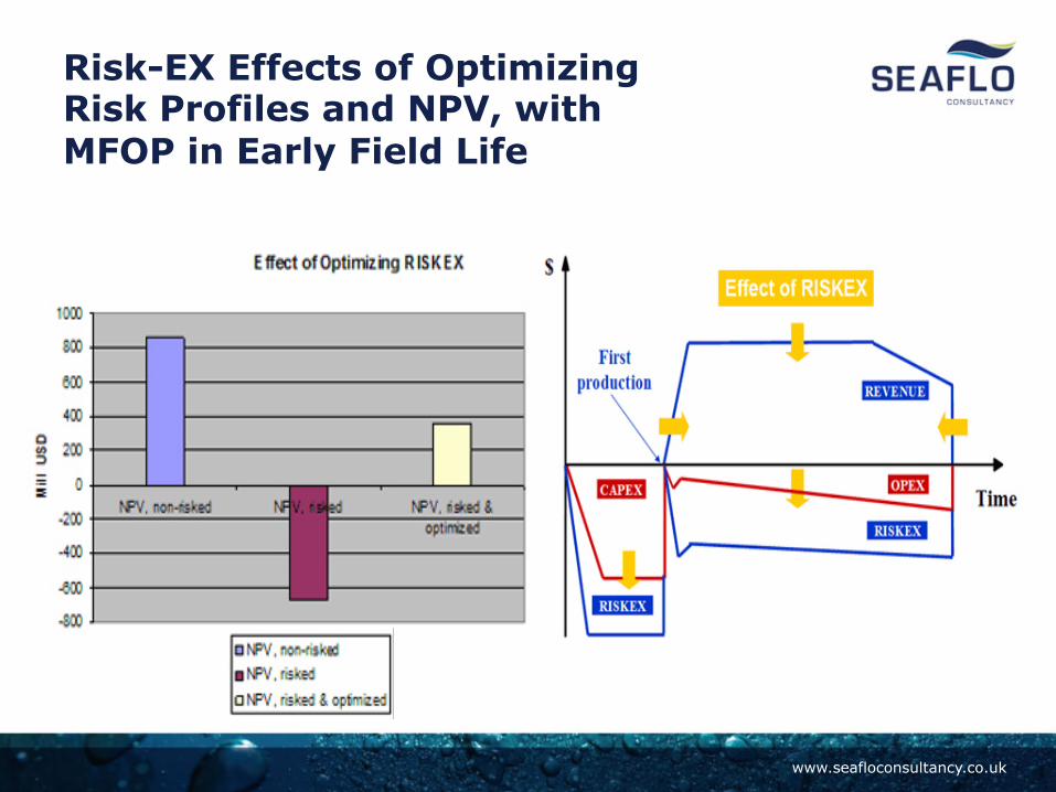
Risk-EX Effects of Optimizing Risk Profiles and NPV, with MFOP in Early Field Life

www.seafloconsultancy.co.uk
‘ RISKEX ’ This figure illustrates how different RISKEX™ components affect different parts of the project lifecycle, such as CAPEX, OPEX, production and revenue changes, time of 1st Oil or Gas and production profile shape elements.
How to Achieve Improved Availability Uptime, Reduce your OPEX and Asset Risk Profile

www.seafloconsultancy.co.uk 7 - COMOPS Meeting 8th Dec, 11
Long Offset Subsea – Tie Back 140 Km to shore with over 230 Km export pipelines

www.seafloconsultancy.co.uk Flow Assurance – OPS 2011
TORMORE MANIFOLD
LAGGAN MANIFOLD
2 x 18” PRODUCTION PIPELINES – 140 km
SEVEN SEAS – 2012
MEG LINE AND SERVICE LINE UMBILICAL
Dual 18” Flowlines, 8” Meg Injection, 3” Service Line and Umbilical

www.seafloconsultancy.co.uk
One of Worlds Longest Umbilical Installations- with a Critical Weather Window over the initial 125km
www.seafloconsultancy.co.uk
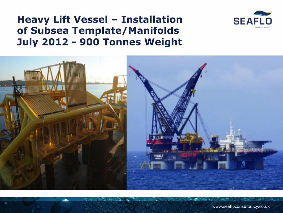
Heavy Lift Vessel – Installation of Subsea Template/Manifolds July 2012 - 900 Tonnes Weight

www.seafloconsultancy.co.uk 11 09/11/2015
SPS- (API-RP-17N *MFOP criteria) Operating Performance, Acceptance Standards • Performance / Operability
Standards & Acceptance Criteria were set within the Production Assurance Programme-PAP

www.seafloconsultancy.co.uk
ROV–ROT Intervention Tooling Accessibility Checks via Simulator

www.seafloconsultancy.co.uk
Subsea Compression Required in Life of Field Operations
Modular Design Interface Built Into Template/Manifolds, Close to Well Slots

www.seafloconsultancy.co.uk 14 PAP Programme
09/11/2015
Production Assurance Programme (PAP) - Moving Forward
• Incentive mechanism to primary contracting entities to deliver high reliability, operability and asset integrity.
• Improve the maintenance free operating period (MFOP) from FMECA and RAM analysis outputs.
• Develop IMR Vessel Strategy and reduce operational- Intervention life cycle risks.

www.seafloconsultancy.co.uk 15 PAP Programme 09/11/2015
PAP-Strategy Framework - Lifecycle Levels
Por?olio Management-‐Level 1 Strategic Asset the
Business case – value adding contribuEon. Programme Management Level 2-‐ The planning
level of PAP into asset-‐operaEons. Level 3 & 4 ImplementaLon & ExecuLon modes of developing the Subsea Performance Standards-‐Integrity criteria +IMR Strategy Plan–Reliability
Assurance Documents-‐Procedures + Manuals, etc.

www.seafloconsultancy.co.uk
API-RP-17N - Production Assurance Programme - Reliability / Availability
Design
Detail Design Manufacture
Install
Operate Failure -Mitigations
errors
defects
Errors Defects
Prev
ent
Prev
ent
Prev
ent
Prev
ent
Reliability led Design + FMECA and RAM Analysis + PAP Installation risk mitigation planning
Data collection Data analysis Feedback Feedback Feedback Feedback
Quality& Reliability led Manufacture Qualification testing
Pre-commissioning – Ops (Risk) assessment-procedure checks
IMR Strategy - PLAN + Risk based inspection Monitoring

www.seafloconsultancy.co.uk Laggan Tormore Project 09/11/2015
Production Assurance Programme – PAP Where we are today !
• API-‐RP-‐17N is sEll relaEvely new by applicaEon across the industry, not all operators have a General SpecificaEon (GS) or defined requirements in terms of how to develop reliability /availability across SPS contract’s.
• Most operators align to API-‐RP-‐17N and seek subsea producEon systems availability to 96 % -‐ greater than > via safe operaEng pracEces, with high reliability management.
www.seafloconsultancy.co.uk
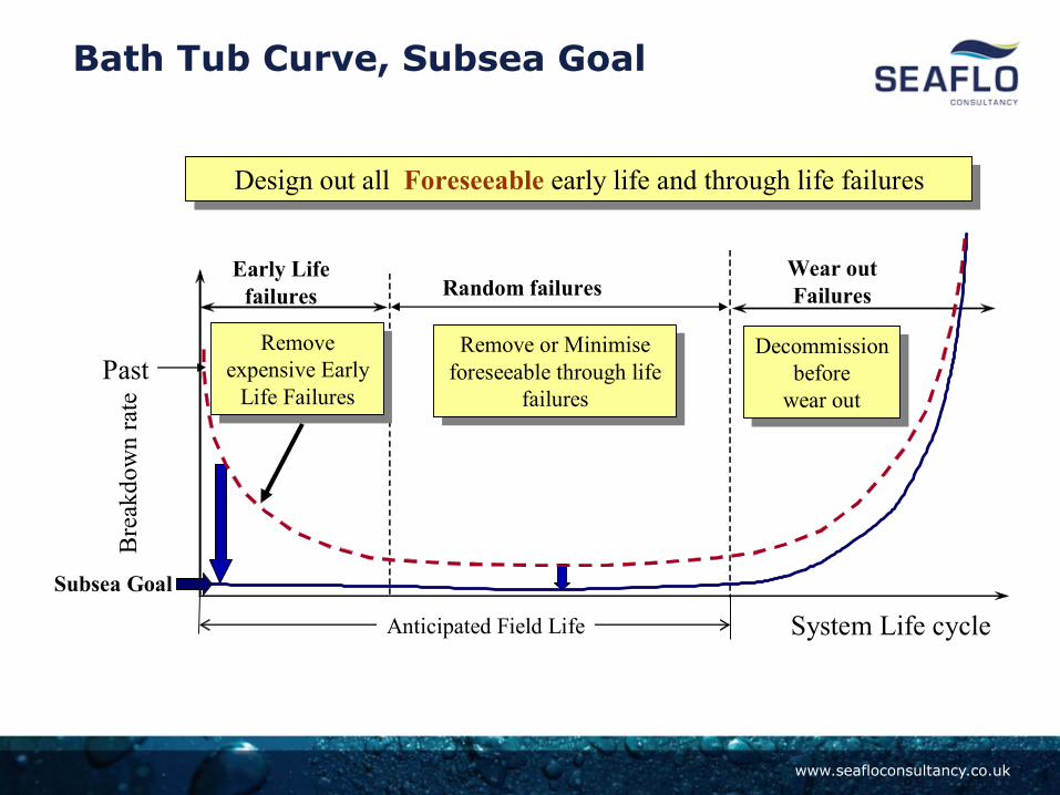
Bath Tub Curve, Subsea Goal
B
reak
dow
n ra
te
System Life cycle
Early Life failures Random failures
Wear out Failures
Remove expensive Early
Life Failures
Remove expensive Early
Life Failures
Design out all Foreseeable early life and through life failures Design out all Foreseeable early life and through life failures
Past
Subsea Goal
Decommission before
wear out
Decommission before
wear out
Remove or Minimise foreseeable through life
failures
Remove or Minimise foreseeable through life
failures
Anticipated Field Life

www.seafloconsultancy.co.uk
Condition Performance Monitoring Across Subsea Production Systems
• Dual Redundant Channel Modules
• Monitoring abnormal trends, in pressures, temperatures, sensor readings, reporting and alerting to Control Room Operators
• Back to operations support teams in office Desk-Top

www.seafloconsultancy.co.uk
Condition Performance Monitoring
• Identify abnormal trends, diagnose, advise and alert. Data Collector, Event Logs, Historian data base.
• Stable asset integrity across the life cycle via effective risk management tools.
Asset Integrity Management Services

www.seafloconsultancy.co.uk
“LIFE OF FIELD” – SUBSEA INSPECTION, INTERVENTION, MAINTENANCE AND REPAIR (IMR) VESSEL CONTRACTING AGREEMENT
Asset Integrity Management Services
Early Contractual Engagement for Subsea (IMR ) Vessel

www.seafloconsultancy.co.uk
Regionally Shared Vessel; (IMR) specification, tool pool of ROV Intervention Tooling, common interfaces, ISO 13628-8- ST 001,+ Critical Spares
IMR Vessel Strategy 09/11/2015

www.seafloconsultancy.co.uk
Why –Subsea Integrity Management is Important
23 Laggan -Tormore 09/11/2015
“Aims to ensure the integrity of an asset within a set of specified operational limitations throughout the lifecycle ”
Ref- DNV-OS codes of practice
Verify, to be in compliance with original design specifications
www.seafloconsultancy.co.uk
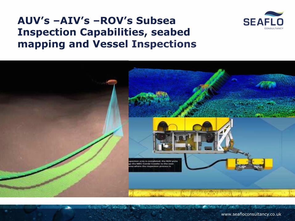
AUV’s –AIV’s –ROV’s Subsea Inspection Capabilities, seabed mapping and Vessel Inspections

www.seafloconsultancy.co.uk
AIV’s & Pipeline Scanning Tools support Subsea Integrity Management Inspection Regimes

www.seafloconsultancy.co.uk
Subsea Wells to Floating Production Systems

www.seafloconsultancy.co.uk
Integrated Dynamic Analysis of Floating Production Vessels and Subsea Infrastructure, Riser Systems

www.seafloconsultancy.co.uk
Vessel Hull characteristics, Dis-connectable Turrets, Sea State Conditions, +40 Years Basis Of Design

www.seafloconsultancy.co.uk
Some FLNG Vessel Design Considerations for High Subsea Uptime
• Limitation of excessive FLNG vessel motions impacting operability and any steel catenary riser designs.
• Mooring system line failure or inability to cope with future surface
facility and riser upgrades.
• Inability of the riser to vessel interface design to accommodate any future expansion requirements.
• Riser System Inspection or Failure Prevention. • Subsea Power Supply or Chemical Injection System availability.
• Offloading System Availability.
• Storage and Ballast System Failure (inability to offload hydrocarbons due to resulting global hull strength constraints).

www.seafloconsultancy.co.uk
Roll Raos at beam seas
0.00E+00
5.00E-01
1.00E+00
1.50E+00
2.00E+00
2.50E+00
3.00E+00
3.50E+00
4.00E+00
4.50E+00
5.00E+00
0.00 5.00 10.00 15.00 20.00 25.00 30.00
Period (sec)
Ampl
itude
(deg
./m)
Bilge radius = 2.50mBilge radius = 1.80mBilge radius = 1.50mBilge radius = 0.80m
The Effect of Bilge Radius Reduction Analysis on Floating Production System Motions Analysis Output from new build floater Roll Raos at beam seas
0.00E+00
5.00E-01
1.00E+00
1.50E+00
2.00E+00
2.50E+00
3.00E+00
3.50E+00
4.00E+00
4.50E+00
5.00E+00
0.00 5.00 10.00 15.00 20.00 25.00 30.00
Period (sec)
Ampli
tude (
deg./
m)
Bilge radius = 2.50mBilge radius = 1.80mBilge radius = 1.50mBilge radius = 0.80m

www.seafloconsultancy.co.uk
• Currently little experience regarding failure types and operational issues experienced with LNG Offloading systems at sea. Potentially insufficient data available for a meaningful system RAM analysis.
• Recent design concepts are based on tandem offloading in conjunction
with a conventional mooring hawser system and a cryogenic offloading hoses often supplied in 12m sections for easy IMR. Offloading hose design life is still being debated, hence consideration should be given to redundancy in the system.
• Currently this concept appears to be the most CAPEX and OPEX efficient. • A safety benefit of the tandem offloading system based on a mooring
hawser and offloading hoses is the increased distance between the FLNG facility and the LNG carrier (70 – 100m) reducing collision risks and domino effects.
• A dedicated DP LNG shuttle tanker (carrier) would potentially allow for
offloading concepts based on offloading from a mid-ships manifold.
FLNG Facility - LNG Offloading System - Designs and Availability Issues

www.seafloconsultancy.co.uk
LNG Offloading System Mooring Howser and Cryogenic Hoses-in Tandem offloading System

www.seafloconsultancy.co.uk
Subsea Wells to FLNG, LNG Offloading Evolving Technology, Needs to Deliver Safe, Robust and Reliable Design Solutions
•

www.seafloconsultancy.co.uk
Monetizing Stranded Gas Fields: Shell Prelude Significant Offshore FLNG Facility
600,000 Tonnes x 488 m Long. Bigger than the Empire State building and is a Floating Production Facility.

www.seafloconsultancy.co.uk
FLNG Barge with Moored FSRU-LNG Carrier Offloading LNG Carrier Offloading Facility, Multi (3) Body Model Dynamic Analysis, Complex Mooring Arrangements, Operability / Availability Uptime
www.seafloconsultancy.co.uk
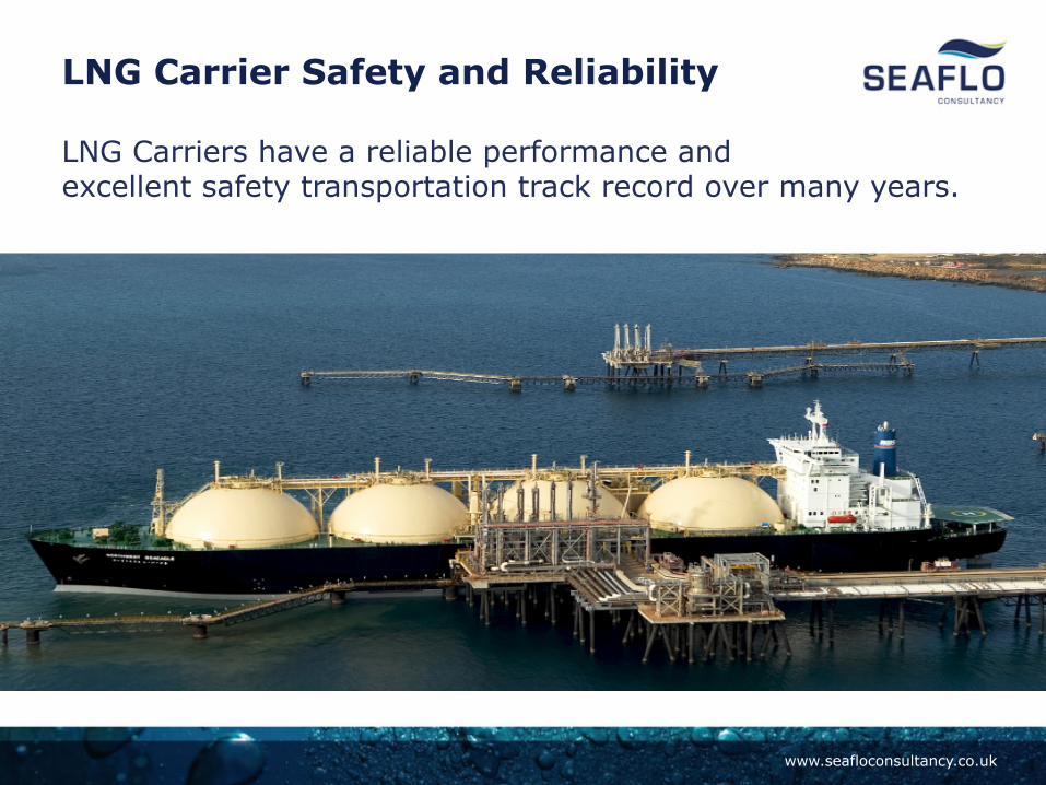
LNG Carriers have a reliable performance and excellent safety transportation track record over many years.
LNG Carrier Safety and Reliability

www.seafloconsultancy.co.uk
LNG Carrier Development

www.seafloconsultancy.co.uk
Ageing Assets & Life Extension Regimes
Project Example: • Implications on Agreed Operating Life expectations, Asset
Integrity, CAPEX and OPEX budgets, sparing philosophy, and agreed minimum operating spare parts lists.
• Implications on pertinent Regulatory or Code changes. • Class Rules and Maintenance of Floating Production facility
in Class.
• Safety Case and defined Safety Critical Elements (SCE), 3rd Party (IRC) and or Client Self Verification Requirements.
• Re-commissioning, Decommissioning Budget Costs. • Implications for facilities IMR Strategy.

www.seafloconsultancy.co.uk
Life Extension – Process
• Criticality system reviews, component risk based assessments were carried out in 2 Phases- 1. Preliminary & 2. Detailed reviews, analysis and re- design calculations performed where applicable
Evaluation Define Components
Assess BOD , consider Failure Consequences
Define Probability of Failure
Business Environment Safety CriEcal Elements
Likelihood Time Element Current Status Anomalies
Review and conduct risk based assessments, document
miEgaEons
Define InspecEon Type & Frequency changes in IRM where appropriate.
Available Methods Applicability + Industry best pracEces.
Follow agreed methodology –flow diagram Phase 1, 2.
Original –Design
Document
Ageing Assets & Life Extension Regimes

www.seafloconsultancy.co.uk
Field Life Extension Philosophy Age
Ageing Assets & Life Extension Regimes

www.seafloconsultancy.co.uk
LE Screening Process Ageing Assets and Life Extension Regimes for Subsea to Floaters
www.seafloconsultancy.co.uk
The Reliability Philosophy
‘Leave no
stone unturned’ Make every possible effort to check and verify all equipment design, operaEng envelope condiEons, funcEonaliEes, interfaces and performance criteria are in
acceptable state before installaEon deployment subsea.

www.seafloconsultancy.co.uk
Lessons Learned
• Create a project environment, encouraging CAPEX and OPEX optimized risk control process for the design, operation, IMR and, if applicable, life extension of the complete field facilities.
• For a field development, both subsea and surface facilities system reliability
and availability requirements and associated design, operating and IMR solutions from wellhead to point of export should be developed in an integrated manner to allow for an overall optimization of CAPEX, OPEX and Life Time Costs.
• FMEA and RAM Analysis and incorporation of analysis results into the facilities
designs should be an ongoing process through all project design phases.
• Project Management to allow for in project budgets and Level 3 schedules for reliability, redundancy, robustness, expansion, IMR, sparing and life extension during early design phases and in the basis of design, technical specifications and contract scope of work documents.
• A strong management focus on CAPEX reductions may result in significantly increased life time costs, safety and environmental risks.

www.seafloconsultancy.co.uk
Lessons Learned
• Create the right working environment across project execution teams, with a realistic focus on both CAPEX to OPEX and Asset Integrity, Life of Field implications.
• Supply Chain Capacity, availability of certain materials globally.
• People understanding, appreciating
The importance of FMECA & RAM
analysis outputs
• Engineering Design house experience in the use and application of API-RP-17N in Pre-Feed or FEED was mixed not a consistent understanding of how to apply it. Thereafter, once in Execute mode difficult to implement.
• Data to support MFOP criteria not well defined
• FLNG systems is still new technology
Life of Field Operability, Asset
Integrity with high Reliability/
Availability
Reduce Design Complexity
Remove poor
Designs Before
Installation
SPS EPC and EPCI-SURF Contracting Strategies

www.seafloconsultancy.co.uk
Equipment Standardisation
Conclusions: • Clear guidance on techniques • API 17’s, NORSOK U001,
DNVGL-RP0002 • Experience gap,
focus on detail • Reliability Engineering is key • Create the right working
environment with right culture
• It is a Cyclic Industry, Low oil prices
• Simplification • It’s a Risky Business
-Effective Project Management Execution Delivery teams is required
Cost Reductions will come from
more standardisation
Reduce Complexity
Remove Defects Before
Installation
Results in Reduced Risk

www.seafloconsultancy.co.uk
The Reliability Philosophy Conclusions: • Encourage the use of standard
equipment design solutions. • More proactive approach to
obsolescence issues. • DNV-RP-0401 been in place
since 1985 Ref: Safety & Reliability. Criteria for Statement of Compliance
• Latest RP’s, NORSOK U-001 • Updates in SINTEF-OREDA Data • SURFIM JIP Forum, PSA Norway • Adherence will underpin safety,
operability and consistent criteria • FLNG systems are still
new technology • Industry Collaboration,
Share Lessons Learnt
Fault Tolerant Configurations
Reduce Complexity
Remove Defects Before
Installation
Residual Risk

www.seafloconsultancy.co.uk
The Principles of the Reliability Capability Maturity Model
D Definition of Reliability Goals & Requirement
P Organising and planning for Reliability
I
Design and manufacture for Reliability
Risk and Reliability Analysis and Modeling
Verification and Validation
Project Risk Management
Reliability Qualification
Performance Tracking & Data Management
Supply Chain Management
Management of Change
F Reliability Assurance
Organisational Learning
5 Reliability OPTIMISED using adaptive processes.
4 Reliability MANAGED and influences design. Improvements made in response to failures.
3 Reliability DEFINED and measured but there is limited feedback for improvement.
2 REPEATABLE performance but standard procedures do not address reliability/improvement.
1 Reliability uncontrolled and procedures AD-HOC.

www.seafloconsultancy.co.uk
How to Achieve Improved Availability or Uptime
I Drive a Mercedes for Reliable Performance!

www.seafloconsultancy.co.uk
Questions Please ?