reminders - wittig · pdf filereminders product ... bk 1005hm601-tv rohs 600 ±25%...
TRANSCRIPT

14
Notice for TAIYO YUDEN products Please read this notice before using the TAIYO YUDEN products.
REMINDERS
Product information in this catalog is as of October 2013. All of the contents specified herein are subject to change
without notice due to technical improvements, etc. Therefore, please check for the latest information carefully be-
fore practical application or usage of the Products.
Please note that TAIYO YUDEN CO., LTD. shall not be responsible for any defects in products or equipment incor-
porating such products, which are caused under the conditions other than those specified in this catalog or indi-
vidual specification.
Please contact TAIYO YUDEN CO., LTD. for further details of product specifications as the individual specification
is available.
Please conduct validation and verification of products in actual condition of mounting and operating environment
before commercial shipment of the equipment.
All electronic components listed in this catalogue are intended for use in general electronic equipment such as AV/
OA equipment, home electrical appliances, office equipment, and information-communication equipment (mobile
phone, PC, etc.), Medical equipment, Industrial equipment, and in automotive applications (for comfort). Please be
sure to contact TAIYO YUDEN CO., LTD. for further information before using the components for any equipment
which might have a negative impact directly on human life, such as transportation equipment (automotive pow-
ertrain/train/ship control systems, etc.) and traffic signal system.
Please do not incorporate the components into any equipment requiring a high degree of safety and reliability, such
as aerospace equipment, avionics, nuclear control equipment, submarine system, and military equipment.
For use in high safety and reliability-required devices/circuits of general electronic equipment, thorough safety
evaluation prior to use is strongly recommended, and a protective circuit should be designed and installed as nec-
essary.
The contents of this catalog are applicable to the products which are purchased from our sales offices or distribu-
tors (so called “TAIYO YUDEN’s official sales channel”). It is only applicable to the products purchased from any of TAIYO YUDEN’ s official sales channel.
Please note that TAIYO YUDEN CO., LTD. shall have no responsibility for any controversies or disputes that may
occur in connection with a third party's intellectual property rights and other related rights arising from your usage
of products in this catalog. TAIYO YUDEN CO., LTD. grants no license for such rights.
Caution for export
Certain items in this catalog may require specific procedures for export according to “Foreign Exchange and For-
eign Trade Control Law” of Japan, “U.S. Export Administration Regulations”, and other applicable regulations.
Should you have any question or inquiry on this matter, please contact our sales staff.
54 14
hq_i_mlci_BK_e-E02R01
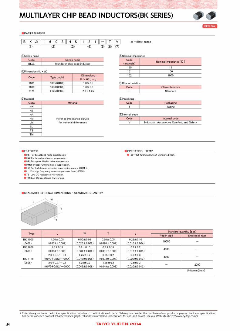
MULTILAYER CHIP BEAD INDUCTORS (BK SERIES)
PARTS NUMBER
B K 1 6 0 8 H S 1 2 1 - T V =Blank space
① ② ③ ④ ⑤ ⑥ ⑦
①Series name
Code Series name
BK Multilayer chip bead inductor
②Dimensions(L×W)
Code Type(inch) Dimensions
(L×W)[mm]
1005 1005(0402) 1.0×0.5
1608 1608(0603) 1.6×0.8
2125 2125(0805) 2.0×1.25
③Material
Code Material
HW
Refer to impedance curves
for material differences
HS
HR
HM
LM
LL
TS
TM
④Nominal impedance
Code
(example) Nominal impedance[Ω]
150 15
101 100
102 1000
⑤Characteristics
Code Characteristics
- Standard
⑥Packaging
Code Packaging
T Taping
⑦Internal code
Code Internal code
V Industrial、Automotive Comfort、and Safety
FEATURES
OPERATING TEMP. HS:For broadband noise suppression.
HW:For broadband noise suppression.
HR:For upper 10MHz noise suppression.
HM:For upper 20MHz noise suppression.
LM:For high frequency noise suppression around 200MHz.
LL:For high frequency noise suppression from 100MHz.
TS:Low DC resistance HS version.
TM:Low DC resistance HM version.
-55~125(Including self-generated heat)
STANDARD EXTERNAL DIMENSIONS / STANDARD QUANTITY
Type L W T e Standard quantity [pcs]
Paper tape Embossed tape
BK 1005
(0402)
1.00±0.05
(0.039±0.002)
0.50±0.05
(0.020±0.002)
0.50±0.05
(0.020±0.002)
0.25±0.10
(0.010±0.004) 10000 -
BK 1608
(0603)
1.6±0.15
(0.063±0.006)
0.8±0.15
(0.031±0.006)
0.8±0.15
(0.031±0.006)
0.3±0.2
(0.012±0.008) 4000 -
BK 2125
(0805)
2.0+0.3/-0.1
(0.079+0.012/-0.004)
1.25±0.2
(0.049±0.008)
0.85±0.2
(0.033±0.008)
0.5±0.3
(0.020±0.012) 4000 -
2.0+0.3/-0.1
(0.079+0.012/-0.004)
1.25±0.2
(0.049±0.008)
1.25±0.2
(0.049±0.008)
0.5±0.3
(0.020±0.012) - 2000
Unit:mm(inch)
MULTILAYER CHIP BEAD INDUCTORS(BK SERIES)REFLOW
Thiscatalogcontainsthetypicalspecificationonlyduetothelimitationofspace.Whenyouconsiderthepurchaseofourproducts,pleasecheckourspecification. Fordetailsofeachproduct(characteristicsgraph,reliabilityinformation,precautionsforuse,andsoon),seeourWebsite(http://www.ty-top.com/).
5514
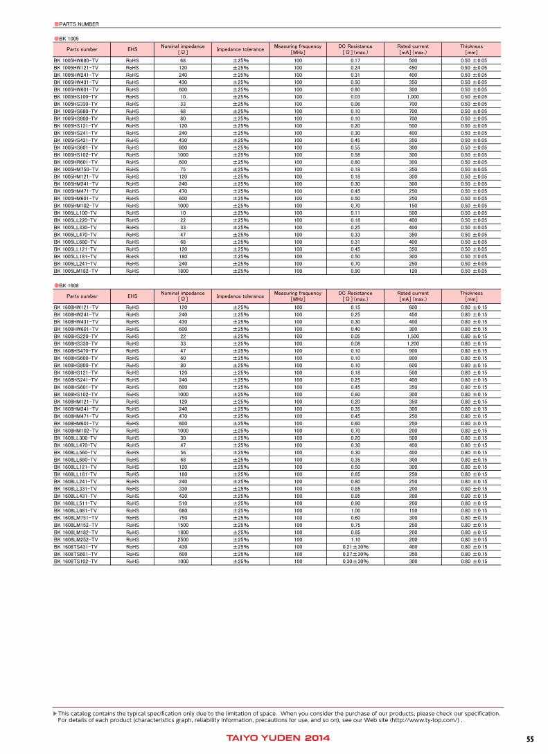
PARTS NUMBER
BK 1005
BK 1005HW680-TV RoHS 68 ±25% 100 0.17 500 0.50 ±0.05
BK 1005HW121-TV RoHS 120 ±25% 100 0.24 450 0.50 ±0.05
BK 1005HW241-TV RoHS 240 ±25% 100 0.31 400 0.50 ±0.05
BK 1005HW431-TV RoHS 430 ±25% 100 0.50 350 0.50 ±0.05
BK 1005HW601-TV RoHS 600 ±25% 100 0.60 300 0.50 ±0.05
BK 1005HS100-TV RoHS 10 ±25% 100 0.03 1,000 0.50 ±0.05
BK 1005HS330-TV RoHS 33 ±25% 100 0.06 700 0.50 ±0.05
BK 1005HS680-TV RoHS 68 ±25% 100 0.10 700 0.50 ±0.05
BK 1005HS800-TV RoHS 80 ±25% 100 0.10 700 0.50 ±0.05
BK 1005HS121-TV RoHS 120 ±25% 100 0.20 500 0.50 ±0.05
BK 1005HS241-TV RoHS 240 ±25% 100 0.30 400 0.50 ±0.05
BK 1005HS431-TV RoHS 430 ±25% 100 0.45 350 0.50 ±0.05
BK 1005HS601-TV RoHS 600 ±25% 100 0.55 300 0.50 ±0.05
BK 1005HS102-TV RoHS 1000 ±25% 100 0.58 300 0.50 ±0.05
BK 1005HR601-TV RoHS 600 ±25% 100 0.60 300 0.50 ±0.05
BK 1005HM750-TV RoHS 75 ±25% 100 0.18 350 0.50 ±0.05
BK 1005HM121-TV RoHS 120 ±25% 100 0.18 300 0.50 ±0.05
BK 1005HM241-TV RoHS 240 ±25% 100 0.30 300 0.50 ±0.05
BK 1005HM471-TV RoHS 470 ±25% 100 0.45 250 0.50 ±0.05
BK 1005HM601-TV RoHS 600 ±25% 100 0.50 250 0.50 ±0.05
BK 1005HM102-TV RoHS 1000 ±25% 100 0.70 150 0.50 ±0.05
BK 1005LL100-TV RoHS 10 ±25% 100 0.11 500 0.50 ±0.05
BK 1005LL220-TV RoHS 22 ±25% 100 0.18 400 0.50 ±0.05
BK 1005LL330-TV RoHS 33 ±25% 100 0.25 400 0.50 ±0.05
BK 1005LL470-TV RoHS 47 ±25% 100 0.33 350 0.50 ±0.05
BK 1005LL680-TV RoHS 68 ±25% 100 0.31 400 0.50 ±0.05
BK 1005LL121-TV RoHS 120 ±25% 100 0.45 350 0.50 ±0.05
BK 1005LL181-TV RoHS 180 ±25% 100 0.50 300 0.50 ±0.05
BK 1005LL241-TV RoHS 240 ±25% 100 0.70 250 0.50 ±0.05
BK 1005LM182-TV RoHS 1800 ±25% 100 0.90 120 0.50 ±0.05
BK 1608
BK 1608HW121-TV RoHS 120 ±25% 100 0.15 600 0.80 ±0.15
BK 1608HW241-TV RoHS 240 ±25% 100 0.25 450 0.80 ±0.15
BK 1608HW431-TV RoHS 430 ±25% 100 0.30 400 0.80 ±0.15
BK 1608HW601-TV RoHS 600 ±25% 100 0.40 300 0.80 ±0.15
BK 1608HS220-TV RoHS 22 ±25% 100 0.05 1,500 0.80 ±0.15
BK 1608HS330-TV RoHS 33 ±25% 100 0.08 1,200 0.80 ±0.15
BK 1608HS470-TV RoHS 47 ±25% 100 0.10 900 0.80 ±0.15
BK 1608HS600-TV RoHS 60 ±25% 100 0.10 800 0.80 ±0.15
BK 1608HS800-TV RoHS 80 ±25% 100 0.10 600 0.80 ±0.15
BK 1608HS121-TV RoHS 120 ±25% 100 0.18 500 0.80 ±0.15
BK 1608HS241-TV RoHS 240 ±25% 100 0.25 400 0.80 ±0.15
BK 1608HS601-TV RoHS 600 ±25% 100 0.45 350 0.80 ±0.15
BK 1608HS102-TV RoHS 1000 ±25% 100 0.60 300 0.80 ±0.15
BK 1608HM121-TV RoHS 120 ±25% 100 0.20 350 0.80 ±0.15
BK 1608HM241-TV RoHS 240 ±25% 100 0.35 300 0.80 ±0.15
BK 1608HM471-TV RoHS 470 ±25% 100 0.45 250 0.80 ±0.15
BK 1608HM601-TV RoHS 600 ±25% 100 0.60 250 0.80 ±0.15
BK 1608HM102-TV RoHS 1000 ±25% 100 0.70 200 0.80 ±0.15
BK 1608LL300-TV RoHS 30 ±25% 100 0.20 500 0.80 ±0.15
BK 1608LL470-TV RoHS 47 ±25% 100 0.30 400 0.80 ±0.15
BK 1608LL560-TV RoHS 56 ±25% 100 0.30 400 0.80 ±0.15
BK 1608LL680-TV RoHS 68 ±25% 100 0.35 300 0.80 ±0.15
BK 1608LL121-TV RoHS 120 ±25% 100 0.50 300 0.80 ±0.15
BK 1608LL181-TV RoHS 180 ±25% 100 0.65 250 0.80 ±0.15
BK 1608LL241-TV RoHS 240 ±25% 100 0.80 250 0.80 ±0.15
BK 1608LL331-TV RoHS 330 ±25% 100 0.85 200 0.80 ±0.15
BK 1608LL431-TV RoHS 430 ±25% 100 0.85 200 0.80 ±0.15
BK 1608LL511-TV RoHS 510 ±25% 100 0.90 200 0.80 ±0.15
BK 1608LL681-TV RoHS 680 ±25% 100 1.00 150 0.80 ±0.15
BK 1608LM751-TV RoHS 750 ±25% 100 0.60 300 0.80 ±0.15
BK 1608LM152-TV RoHS 1500 ±25% 100 0.75 250 0.80 ±0.15
BK 1608LM182-TV RoHS 1800 ±25% 100 0.85 200 0.80 ±0.15
BK 1608LM252-TV RoHS 2500 ±25% 100 1.10 200 0.80 ±0.15
BK 1608TS431-TV RoHS 430 ±25% 100 0.21±30% 400 0.80 ±0.15
BK 1608TS601-TV RoHS 600 ±25% 100 0.27±30% 350 0.80 ±0.15
BK 1608TS102-TV RoHS 1000 ±25% 100 0.30±30% 300 0.80 ±0.15
Measuring frequency[MHz]
DC Resistance[Ω](max.)
Rated current[mA](max.)
Thickness[mm]
Parts number EHSNominal impedance
[Ω]Impedance tolerance
Measuring frequency[MHz]
DC Resistance[Ω](max.)
Rated current[mA](max.)
Thickness[mm]
Parts number EHSNominal impedance
[Ω]Impedance tolerance
hq_i_mlci_BK_e-E02R01
Thiscatalogcontainsthetypicalspecificationonlyduetothelimitationofspace.Whenyouconsiderthepurchaseofourproducts,pleasecheckourspecification. Fordetailsofeachproduct(characteristicsgraph,reliabilityinformation,precautionsforuse,andsoon),seeourWebsite(http://www.ty-top.com/).

56 14
PARTS NUMBER
BK 2125
BK 2125HS150-TV RoHS 15 ±25% 100 0.05 1,200 0.85 ±0.2
BK 2125HS220-TV RoHS 22 ±25% 100 0.05 1,200 0.85 ±0.2
BK 2125HS330-TV RoHS 33 ±25% 100 0.05 1,200 0.85 ±0.2
BK 2125HS470-TV RoHS 47 ±25% 100 0.05 1,000 0.85 ±0.2
BK 2125HS750-TV RoHS 75 ±25% 100 0.10 1,000 0.85 ±0.2
BK 2125HS101-TV RoHS 100 ±25% 100 0.10 900 0.85 ±0.2
BK 2125HS121-TV RoHS 120 ±25% 100 0.15 800 0.85 ±0.2
BK 2125HS241-TV RoHS 240 ±25% 100 0.20 600 0.85 ±0.2
BK 2125HS431-TV RoHS 430 ±25% 100 0.25 500 0.85 ±0.2
BK 2125HS601-TV RoHS 600 ±25% 100 0.30 500 0.85 ±0.2
BK 2125HS102-TV RoHS 1000 ±25% 100 0.40 300 0.85 ±0.2
BK 2125HM121-TV RoHS 120 ±25% 100 0.15 800 0.85 ±0.2
BK 2125HM241-TV RoHS 240 ±25% 100 0.20 600 0.85 ±0.2
BK 2125HM471-TV RoHS 470 ±25% 100 0.25 500 0.85 ±0.2
BK 2125HM601-TV RoHS 600 ±25% 100 0.25 500 0.85 ±0.2
BK 2125HM102-TV RoHS 1000 ±25% 100 0.35 400 0.85 ±0.2
BK 2125LL560-TV RoHS 56 ±25% 100 0.20 600 0.85 ±0.2
BK 2125LL121-TV RoHS 120 ±25% 100 0.30 400 0.85 ±0.2
BK 2125LL241-TV RoHS 240 ±25% 100 0.35 300 0.85 ±0.2
BK 2125LM751-TV RoHS 750 ±25% 100 0.30 400 0.85 ±0.2
BK 2125LM152-TV RoHS 1500 ±25% 100 0.35 400 0.85 ±0.2
BK 2125LM182-TV RoHS 1800 ±25% 100 0.45 300 1.25 ±0.2
BK 2125LM252-TV RoHS 2500 ±25% 100 0.75 200 1.25 ±0.2
Measuring frequency[MHz]
DC Resistance[Ω](max.)
Rated current[mA](max.)
Thickness[mm]
Parts number EHSNominal impedance
[Ω]Impedance tolerance
hq_i_mlci_BK_e-E02R01
Thiscatalogcontainsthetypicalspecificationonlyduetothelimitationofspace.Whenyouconsiderthepurchaseofourproducts,pleasecheckourspecification. Fordetailsofeachproduct(characteristicsgraph,reliabilityinformation,precautionsforuse,andsoon),seeourWebsite(http://www.ty-top.com/).
5714
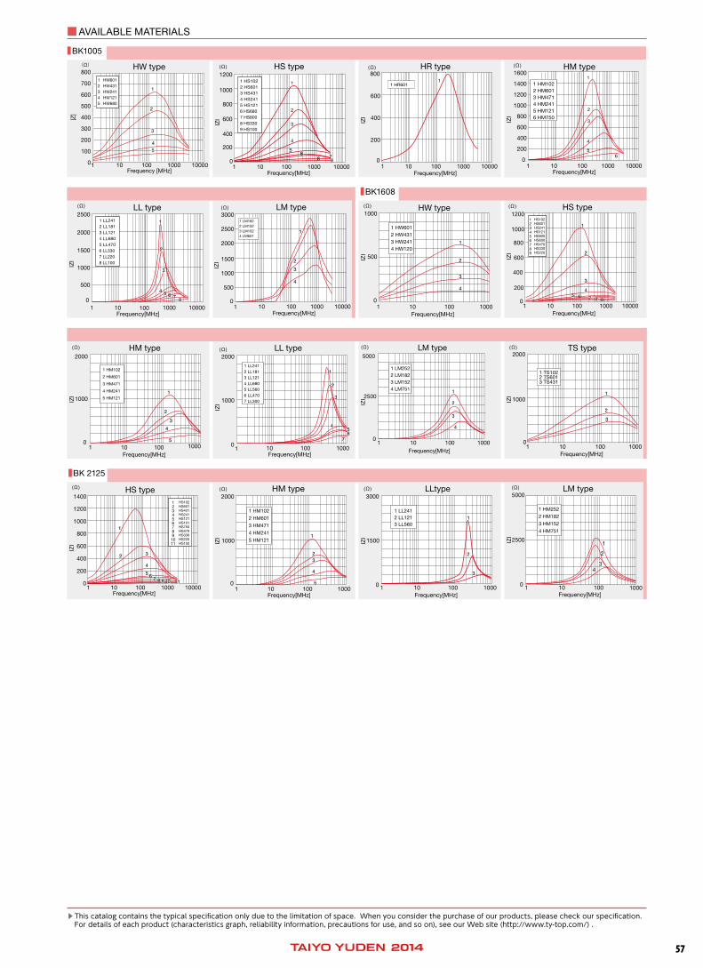
AVAILABLE MATERIALS
1200
01 10 100 1000 10000
200
400
600
800
1000
(Ω)
Frequency[MHz]
IZI
HS type
1 HS1022 HS6013 HS4314 HS2415 HS1216 HS6807 HS8008 HS3309 HS100
1
2
3
4
566
77988
IZI
01 10 100 1000 10000
200
400
600
800(Ω)
Frequency[MHz]
HR type
1 HR6011
01 10 100 1000 10000
200
400
600
800
1000
1200
1400
1600(Ω)
Frequency[MHz]
IZI
HM type
1 HM1022 HM6013 HM4714 HM2415 HM1216 HM750
1
2
3
4
556
2500
IZI
01 10 100 1000 10000
500
1000
1500
2000
(Ω)
Frequency[MHz]
LL type1 LL2412 LL1813 LL1214 LL6805 LL4706 LL3307 LL2208 LL100
11
22
33
44 55 66 7788
IZI
010 100 1000 10000
500
1000
1500
2000
2500
3000(Ω)
Frequency[MHz]
LM type
1
1 LM1822 LM1523 LM1024 LM601
11
22
33
44
IZI
01 10 100 1000
500
1000(Ω)
Frequency[MHz]
HW type
1 HW6012 HW4313 HW2414 HW120
11
22
33
44
IZI
01 10 100 1000 10000
200
400
600
800
1000
1200(Ω)
Frequency[MHz]
HS type123456789
HS102HS601HS241HS121HS800HS600HS470HS330HS220
66 77 88 9955
11
22
33
44
IZI
01 10 100 1000
1000
2000(Ω)
Frequency[MHz]
LL type
1 LL2411 LL2412 LL1813 LL1214 LL6805 LL5606 LL4707 LL300
6677
11
22
33
4455
IZI
5000
2500
0
1 LM2522 LM1823 LM1524 LM751
(Ω)
1 10 100 1000Frequency[MHz]
LM type
11
22
33
44
IZI
01 10 100 1000
1000
2000
(Ω)
Frequency[MHz]
HM type
1 HM102
2 HM601
3 HM471
4 HM241
5 HM12111
22
33
44
55
IZI
1 TS1022 TS6013 TS431
01 10 100 1000
1000
2000(Ω)
Frequency[MHz]
TS type
11
22
33
800
700
600
500
400
300
200
100
0
(Ω)
100 100001000101Frequency [MHz]
HW type|Z
|
1
2
3
4
5
1 HW6012 HW431 3 HW2414 HW1215 HW680
BK1005
BK1608
IZI
01 10 100 1000 10000
200
400
600
800
1000
1200
1400
(Ω)
Frequency[MHz]
HS type1234567891011
HS102HS601HS431HS241HS121HS101HS750HS470HS330HS220HS150
66 77 88 99 1010 1111
11
22 33
44
55
IZI
01 10 100 1000
1000
2000(Ω)
Frequency[MHz]
HM type
1 HM102
2 HM601
3 HM471
4 HM241
5 HM12111
2233
44
55
IZI
1 LL2412 LL1213 LL560
0 1 10 100 1000
1500
3000(Ω)
Frequency[MHz]
LLtype
11
22
33
0 1 10 100 1000
2500
5000(Ω)
Frequency[MHz]
IZI
LM type
1 HM252
2 HM182
3 HM152
4 HM751
1
2
3344
BK 2125
Thiscatalogcontainsthetypicalspecificationonlyduetothelimitationofspace.Whenyouconsiderthepurchaseofourproducts,pleasecheckourspecification. Fordetailsofeachproduct(characteristicsgraph,reliabilityinformation,precautionsforuse,andsoon),seeourWebsite(http://www.ty-top.com/).

58 14
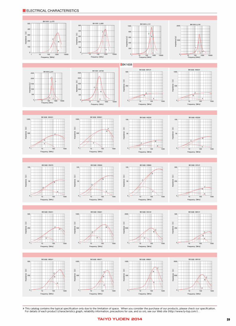
BK1005 HW121250
200
150
100
50
0
Frequency [MHz]
Imp
edan
ce[Ω]
100101 1000 10000
Z
R
X
BK1005 HW241500
400
300
200
100
0
Frequency [MHz]
Imp
edan
ce[Ω]
100101 1000 10000
R
X
Z
BK1005 HW4311000
800
600
400
200
0
Frequency [MHz]
Imp
edan
ce[Ω]
100101 1000 10000
R
X
Z
BK1005 HW6011000
800
600
400
200
0
Frequency [MHz]
Imp
edan
ce[Ω]
100101 1000 10000
R
X
Z
BK1005 HS100100
80
60
40
20
0
Frequency [MHz]
Imp
edan
ce[Ω]
100101 1000 10000
RX
Z
BK1005 HS330100
80
60
40
20
0
Imp
edan
ce[Ω]
100101 1000 10000
Frequency [MHz]
R
X
Z
BK1005 HS680250
200
150
100
50
0
Frequency [MHz]
Imp
edan
ce[Ω]
100 100001000101
X
Z
R
250
200
150
100
50
0
BK1005 HS800250
200
150
100
50
0
Frequency [MHz]
Imp
edan
ce[Ω]
100101 1000 10000
R
X
Z
BK1005 HW680
Frequency [MHz]
Imp
edan
ce[Ω]
250
200
150
100
50
0100101 1000 10000
RX
Z
BK1005
ELECTRICAL CHARACTERISTICS
BK1005 HS4311000
800
600
400
200
0100101 100001000
Frequency [MHz]
Imp
edan
ce[Ω]
RRX
ZZ
RRX
ZZ
BK1005 HS1022000
1000
01000100101 10000
Frequency [MHz]
Imp
edan
ce[Ω]
BK1005 HR6011000
800
600
400
200
0
BK1005 HM750200
150
100
50
0
BK1005 HM121250
200
150
100
50
0100 1000101 10000
Frequency [MHz]
Imp
edan
ce[Ω]
RR
X
Z
500
100
200
300
400
1 10 100 1000 100000
2000
1000
01 10 1000100 10000
BK1005 HM102250
150
200
100
50
01 10 100 1000 10000
BK1005 LL100250
200
150
100
50
01 10 100 1000 10000
BK1005 LL220500
400
300
200
100
01 10 100 1000 10000
BK1005 LL330
Thiscatalogcontainsthetypicalspecificationonlyduetothelimitationofspace.Whenyouconsiderthepurchaseofourproducts,pleasecheckourspecification. Fordetailsofeachproduct(characteristicsgraph,reliabilityinformation,precautionsforuse,andsoon),seeourWebsite(http://www.ty-top.com/).
5914
ELECTRICAL CHARACTERISTICS
500
400
300
200
100
01 10 100 1000 10000
BK1005 LL470
500
400
300
200
100
01 10 100 1000 10000
BK1005 LL680
2500
2000
1500
1000
500
01 10 100 100001000
BK1005 LM182
RR
X
ZZ
BK1608
Thiscatalogcontainsthetypicalspecificationonlyduetothelimitationofspace.Whenyouconsiderthepurchaseofourproducts,pleasecheckourspecification. Fordetailsofeachproduct(characteristicsgraph,reliabilityinformation,precautionsforuse,andsoon),seeourWebsite(http://www.ty-top.com/).

60 14
ELECTRICAL CHARACTERISTICS
500
250
01 10 100 1000 10000
BK1608 LL300500
250
01 10 100 1000 10000
BK1608 LL470500
250
01 10 100 1000 10000
BK1608 LL560500
250
01 10 100 1000 10000
BK1608 LL680
1500
750
01 10 100 1000
BK1608 LL121
2000
4000
BK2125
Thiscatalogcontainsthetypicalspecificationonlyduetothelimitationofspace.Whenyouconsiderthepurchaseofourproducts,pleasecheckourspecification. Fordetailsofeachproduct(characteristicsgraph,reliabilityinformation,precautionsforuse,andsoon),seeourWebsite(http://www.ty-top.com/).

6114
ELECTRICAL CHARACTERISTICS
R
Z
X
10001001010
500
1000
R
Z
10001001010
500
1000
X
Thiscatalogcontainsthetypicalspecificationonlyduetothelimitationofspace.Whenyouconsiderthepurchaseofourproducts,pleasecheckourspecification. Fordetailsofeachproduct(characteristicsgraph,reliabilityinformation,precautionsforuse,andsoon),seeourWebsite(http://www.ty-top.com/).
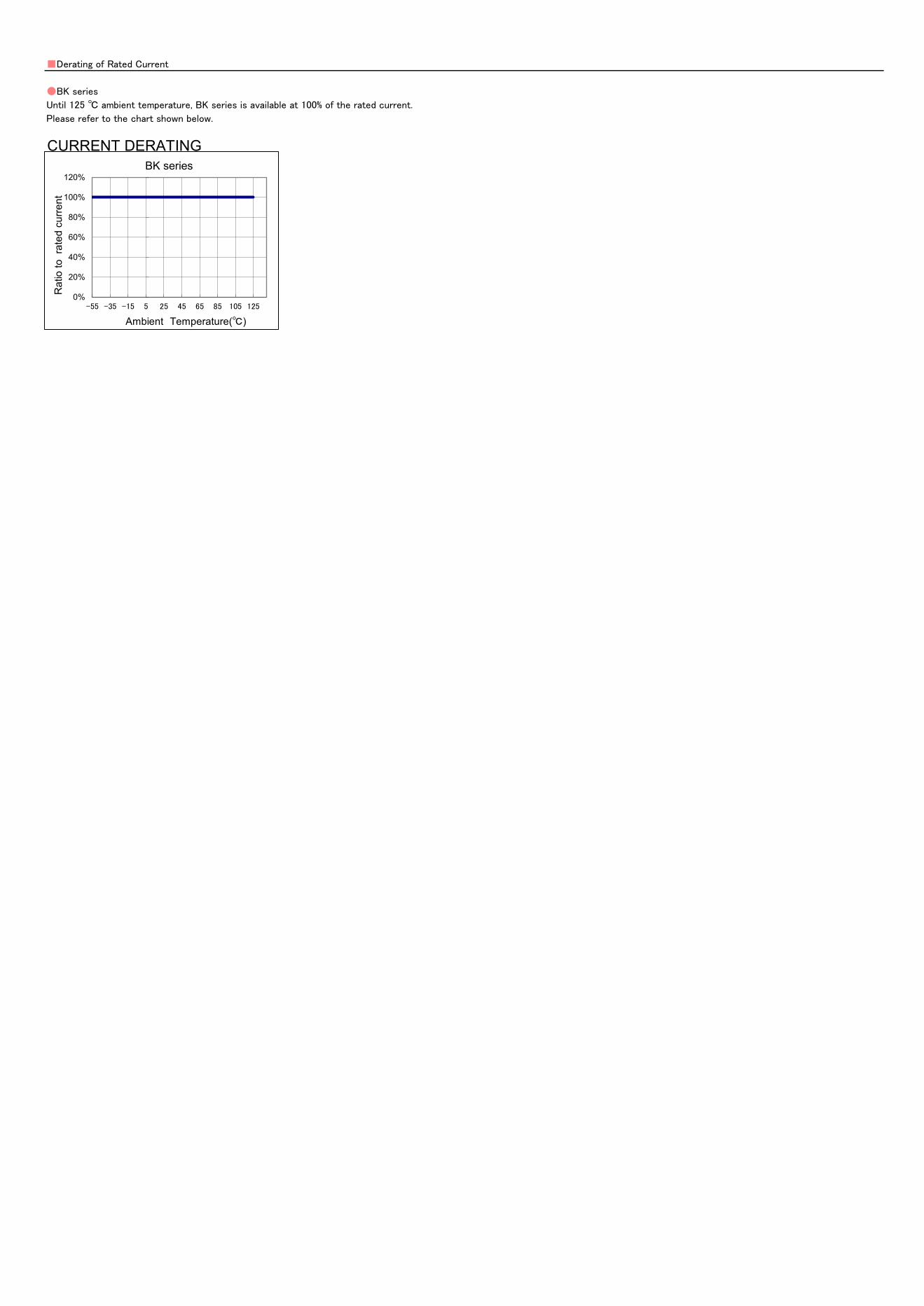
Derating of Rated Current
BK series
Until 125 ambient temperature, BK series is available at 100% of the rated current.
Please refer to the chart shown below.
CURRENT DERATING
0%
20%
40%
60%
80%
100%
120%
-55 -35 -15 5 25 45 65 85 105 125
Rat
io to
rat
ed c
urre
nt
Ambient Temperature()
BK series

This catalog contains the typical specification only due to the limitation of space. When you consider the purchase of our products, please check our specification.
For details of each product (characteristics graph, reliability information, precautions for use, and so on), see our Web site (http://www.ty-top.com/) .
i_mlci_pack_e-E02R01
Multilayer chip inductors
Multilayer chip inductors for high frequency, Multilayer chip bead inductors
Multilayer common mode choke coils(MC series F type)
PACKAGING
①Minimum Quantity
Tape & Reel Packaging
Type Thickness
mm(inch)
Standard Quantity [pcs]
Paper Tape Embossed Tape
CK1608(0603) 0.8 (0.031) 4000 -
CK2125(0805) 0.85(0.033) 4000 -
1.25(0.049) - 2000
CKS2125(0805) 0.85(0.033) 4000 -
1.25(0.049) - 2000
CKP1608(0603) 0.8 (0.031) 4000 -
CKP2012(0805) 0.9 (0.035) - 3000
CKP2016(0806) 0.9 (0.035) - 3000
CKP2520(1008)
0.7 (0.028) - 3000
0.9 (0.035) - 3000
1.1 (0.043) - 2000
NM2012(0805) 0.9 (0.035) - 3000
NM2520(1008) 0.9 (0.035) - 3000
1.1 (0.043) - 2000
LK1005(0402) 0.5 (0.020) 10000 -
LK1608(0603) 0.8 (0.031) 4000 -
LK2125(0805) 0.85(0.033) 4000 -
1.25(0.049) - 2000
HK0402(01005) 0.2 (0.008) 20000 -
HK0603(0201) 0.3 (0.012) 15000 -
HK1005(0402) 0.5 (0.020) 10000 -
HK1608(0603) 0.8 (0.031) 4000 -
HK2125(0805) 0.85(0.033) - 4000
1.0 (0.039) - 3000
HKQ0402(01005) 0.2 (0.008) 20000 40000
HKQ0603W(0201) 0.3 (0.012) 15000 -
HKQ0603C(0201) 0.3 (0.012) 15000 -
HKQ0603S(0201) 0.3 (0.012) 15000 -
HKQ0603U(0201) 0.3 (0.012) 15000 -
AQ105(0402) 0.5 (0.020) 10000 -
BK0402(01005) 0.2 (0.008) 20000 -
BK0603(0201) 0.3 (0.012) 15000 -
BK1005(0402) 0.5 (0.020) 10000 -
BKH0603(0201) 0.3 (0.012) 15000 -
BKH1005(0402) 0.5 (0.020) 10000 -
BK1608(0603) 0.8 (0.031) 4000 -
BK2125(0805) 0.85(0.033) 4000 -
1.25(0.049) - 2000
BK2010(0804) 0.45(0.018) 4000 -
BK3216(1206) 0.8 (0.031) - 4000
BKP0603(0201) 0.3 (0.012) 15000 -
BKP1005(0402) 0.5 (0.020) 10000 -
BKP1608(0603) 0.8 (0.031) 4000 -
BKP2125(0805) 0.85(0.033) 4000 -
MCF0605(0202) 0.3 (0.012) 15000 -
MCF0806(0302) 0.4 (0.016) - 10000
MCF1210(0504) 0.55(0.022) - 5000
MCF2010(0804) 0.45(0.018) - 4000
This catalog contains the typical specification only due to the limitation of space. When you consider the purchase of our products, please check our specification.
For details of each product (characteristics graph, reliability information, precautions for use, and so on), see our Web site (http://www.ty-top.com/) .
i_mlci_pack_e-E02R01
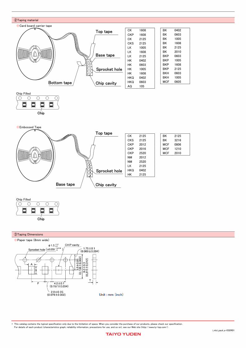
②Taping material
Card board carrier tape
Top tape
Base tape
Sprocket hole
Bottom tape Chip cavity
Chip Filled
Chip
CK 1608
CKP 1608
CK 2125
CKS 2125
LK 1005
LK 1608
LK 2125
HK 0402
HK 0603
HK 1005
HK 1608
HKQ 0402
HKQ 0603
AQ 105
BK 0402
BK 0603
BK 1005
BK 1608
BK 2125
BK 2010
BKP 0603
BKP 1005
BKP 1608
BKP 2125
BKH 0603
BKH 1005
MCF 0605
Embossed Tape
Top tape
Base tape
Sprocket hole
Chip cavity
Chip Filled
Chip
CK 2125
CKS 2125
CKP 2012
CKP 2016
CKP 2520
NM 2012
NM 2520
LK 2125
HKQ 0402
HK 2125
BK 2125
BK 3216
MCF 0806
MCF 1210
MCF 2010
③Taping Dimensions
Paper tape (8mm wide)

This catalog contains the typical specification only due to the limitation of space. When you consider the purchase of our products, please check our specification.
For details of each product (characteristics graph, reliability information, precautions for use, and so on), see our Web site (http://www.ty-top.com/) .
i_mlci_pack_e-E02R01
Type Thickness
mm(inch)
Chip cavity Insertion Pitch Tape Thickness
A B F T
CK1608(0603) 0.8 (0.031) 1.0±0.2
(0.039±0.008)
1.8±0.2
(0.071±0.008)
4.0±0.1
(0.157±0.004)
1.1max
(0.043max)
CK2125(0805) 0.85(0.033) 1.5±0.2
(0.059±0.008)
2.3±0.2
(0.091±0.008)
4.0±0.1
(0.157±0.004)
1.1max
(0.043max)
CKS2125(0805) 0.85(0.033) 1.5±0.2
(0.059±0.008)
2.3±0.2
(0.091±0.008)
4.0±0.1
(0.157±0.004)
1.1max
(0.043max)
CKP1608(0603) 0.8 (0.031) 1.0±0.2
(0.039±0.008)
1.8±0.2
(0.071±0.008)
4.0±0.1
(0.157±0.004)
1.1max
(0.043max)
LK1005(0402) 0.5 (0.020) 0.65±0.1
(0.026±0.004)
1.15±0.1
(0.045±0.004)
2.0±0.05
(0.079±0.002)
0.8max
(0.031max)
LK1608(0603) 0.8 (0.031) 1.0±0.2
(0.039±0.008)
1.8±0.2
(0.071±0.008)
4.0±0.1
(0.157±0.004)
1.1max
(0.043max)
LK2125(0805) 0.85(0.033) 1.5±0.2
(0.059±0.008)
2.3±0.2
(0.091±0.008)
4.0±0.1
(0.157±0.004)
1.1max
(0.043max)
HK0402(01005) 0.2 (0.008) 0.25±0.04
(0.010±0.002)
0.45±0.04
(0.018±0.002)
2.0±0.05
(0.079±0.002)
0.36max
(0.014max)
HK0603(0201) 0.3 (0.012) 0.40±0.06
(0.016±0.002)
0.70±0.06
(0.028±0.002)
2.0±0.05
(0.079±0.002)
0.45max
(0.018max)
HK1005(0402) 0.5 (0.020) 0.65±0.1
(0.026±0.004)
1.15±0.1
(0.045±0.004)
2.0±0.05
(0.079±0.002)
0.8max
(0.031max)
HK1608(0603) 0.8 (0.031) 1.0±0.2
(0.039±0.008)
1.8±0.2
(0.071±0.008)
4.0±0.1
(0.157±0.004)
1.1max
(0.043max)
HKQ0402(01005) 0.2 (0.008) 0.25±0.04
(0.010±0.002)
0.45±0.04
(0.018±0.002)
2.0±0.05
(0.079±0.002)
0.36max
(0.014max)
HKQ0603W(0201) 0.3 (0.012) 0.40±0.06
(0.016±0.002)
0.70±0.06
(0.028±0.002)
2.0±0.05
(0.079±0.002)
0.45max
(0.018max)
HKQ0603C(0201) 0.3 (0.012) 0.40±0.06
(0.016±0.002)
0.70±0.06
(0.028±0.002)
2.0±0.05
(0.079±0.002)
0.45max
(0.018max)
HKQ0603S(0201) 0.3 (0.012) 0.40±0.06
(0.016±0.002)
0.70±0.06
(0.028±0.002)
2.0±0.05
(0.079±0.002)
0.45max
(0.018max)
HKQ0603U(0201) 0.3 (0.012) 0.40±0.06
(0.016±0.002)
0.70±0.06
(0.028±0.002)
2.0±0.05
(0.079±0.002)
0.45max
(0.018max)
AQ105(0402) 0.5 (0.020) 0.75±0.1
(0.030±0.004)
1.15±0.1
(0.045±0.004)
2.0±0.05
(0.079±0.002)
0.8max
(0.031max)
BK0402(01005) 0.2 (0.008) 0.25±0.04
(0.010±0.002)
0.45±0.04
(0.018±0.002)
2.0±0.05
(0.079±0.002)
0.36max
(0.014max)
BK0603(0201) 0.3 (0.012) 0.40±0.06
(0.016±0.002)
0.70±0.06
(0.028±0.002)
2.0±0.05
(0.079±0.002)
0.45max
(0.018max)
BK1005(0402) 0.5 (0.020) 0.65±0.1
(0.026±0.004)
1.15±0.1
(0.045±0.004)
2.0±0.05
(0.079±0.002)
0.8max
(0.031max)
BK1608(0603) 0.8 (0.031) 1.0±0.2
(0.039±0.008)
1.8±0.2
(0.071±0.008)
4.0±0.1
(0.157±0.004)
1.1max
(0.043max)
BK2125(0805) 0.85(0.033) 1.5±0.2
(0.059±0.008)
2.3±0.2
(0.091±0.008)
4.0±0.1
(0.157±0.004)
1.1max
(0.043max)
BK2010(0804) 0.45(0.018) 1.2±0.1
(0.047±0.004)
2.17±0.1
(0.085±0.004)
4.0±0.1
(0.157±0.004)
0.8max
(0.031max)
BKP0603(0201) 0.3 (0.012) 0.40±0.06
(0.016±0.002)
0.70±0.06
(0.028±0.002)
2.0±0.05
(0.079±0.002)
0.45max
(0.018max)
BKP1005(0402) 0.5 (0.020) 0.65±0.1
(0.026±0.004)
1.15±0.1
(0.045±0.004)
2.0±0.05
(0.079±0.002)
0.8max
(0.031max)
BKP1608(0603) 0.8 (0.031) 1.0±0.2
(0.039±0.008)
1.8±0.2
(0.071±0.008)
4.0±0.1
(0.157±0.004)
1.1max
(0.043max)
BKP2125(0805) 0.85(0.033) 1.5±0.2
(0.059±0.008)
2.3±0.2
(0.091±0.008)
4.0±0.1
(0.157±0.004)
1.1max
(0.043max)
BKH0603(0201) 0.3 (0.012) 0.40±0.06
(0.016±0.002)
0.70±0.06
(0.028±0.002)
2.0±0.05
(0.079±0.002)
0.45max
(0.018max)
BKH1005(0402) 0.5 (0.020) 0.65±0.1
(0.026±0.004)
1.15±0.1
(0.045±0.004)
2.0±0.05
(0.079±0.002)
0.8max
(0.031max)
MCF0605(0202) 0.3 (0.012) 0.62±0.03
(0.024±0.001)
0.77±0.03
(0.030±0.001)
2.0±0.05
(0.079±0.002)
0.45max
(0.018max)
Unit : mm(inch)

This catalog contains the typical specification only due to the limitation of space. When you consider the purchase of our products, please check our specification.
For details of each product (characteristics graph, reliability information, precautions for use, and so on), see our Web site (http://www.ty-top.com/) .
i_mlci_pack_e-E02R01
Embossed Tape (8mm wide)
Type Thickness
mm(inch)
Chip cavity Insertion Pitch Tape Thickness
A B F K T
CK2125(0805) 1.25(0.049) 1.5±0.2
(0.059±0.008)
2.3±0.2
(0.091±0.008)
4.0±0.1
(0.157±0.004)
2.0
(0.079)
0.3
(0.012)
CKS2125(0805) 1.25(0.049) 1.5±0.2
(0.059±0.008)
2.3±0.2
(0.091±0.008)
4.0±0.1
(0.157±0.004)
2.0
(0.079)
0.3
(0.012)
CKP2012(0805) 0.9 (0.035) 1.55±0.2
(0.061±0.008)
2.3±0.2
(0.091±0.008)
4.0±0.1
(0.157±0.004)
1.3
(0.051)
0.3
(0.012)
CKP2016(0806) 0.9 (0.035) 1.8±0.1
(0.071±0.004)
2.2±0.1
(0.087±0.004)
4.0±0.1
(0.157±0.004)
1.3
(0.051)
0.25
(0.01)
CKP2520(1008)
0.7 (0.028)
2.3±0.1
(0.091±0.004)
2.8±0.1
(0.110±0.004)
4.0±0.1
(0.157±0.004)
1.4
(0.055)
0.3
(0.012) 0.9 (0.035)
1.4
(0.055)
1.1 (0.043) 1.7
(0.067)
NM2012(0805) 0.9 (0.035) 1.55±0.2
(0.061±0.008)
2.3±0.2
(0.091±0.008)
4.0±0.1
(0.157±0.004)
1.3
(0.051)
0.3
(0.012)
NM2520(1008)
0.9 (0.035) 2.3±0.1
(0.091±0.004)
2.8±0.1
(0.110±0.004)
4.0±0.1
(0.157±0.004)
1.4
(0.055) 0.3
(0.012) 1.1 (0.043)
1.7
(0.067)
LK2125(0805) 1.25(0.049) 1.5±0.2
(0.059±0.008)
2.3±0.2
(0.091±0.008)
4.0±0.1
(0.157±0.004)
2.0
(0.079)
0.3
(0.012)
HK2125(0805)
0.85(0.033) 1.5±0.2
(0.059±0.008)
2.3±0.2
(0.091±0.008)
4.0±0.1
(0.157±0.004)
1.5
(0.059) 0.3
(0.012) 1.0 (0.039)
2.0
(0.079)
BK2125(0805) 1.25(0.049) 1.5±0.2
(0.059±0.008)
2.3±0.2
(0.091±0.008)
4.0±0.1
(0.157±0.004)
2.0
(0.079)
0.3
(0.012)
BK3216(1206) 0.8(0.031) 1.9±0.1
(0.075±0.004)
3.5±0.1
(0.138±0.004)
4.0±0.1
(0.157±0.004)
1.4
(0.055)
0.3
(0.012)
MCF0806(0302) 0.4 (0.016) 0.75±0.05
(0.030±0.002)
0.95±0.05
(0.037±0.002)
2.0±0.05
(0.079±0.002)
0.55
(0.022)
0.3
(0.012)
MCF1210(0504) 0.55(0.022) 1.15±0.05
(0.045±0.002)
1.40±0.05
(0.055±0.002)
4.0±0.1
(0.157±0.004)
0.65
(0.026)
0.3
(0.012)
MCF2010(0804) 0.45(0.018) 1.1±0.1
(0.043±0.004)
2.3±0.1
(0.091±0.004)
4.0±0.1
(0.157±0.004)
0.85
(0.033)
0.3
(0.012)
Unit : mm(inch)
Embossed Tape (4mm wide)
Type Thickness
mm(inch)
Chip cavity Insertion Pitch Tape Thickness
A B F K T
HKQ0402(01005) 0.2 (0.008) 0.23 0.43 1.0±0.02 0.5max. 0.25max.
Unit : mm

This catalog contains the typical specification only due to the limitation of space. When you consider the purchase of our products, please check our specification.
For details of each product (characteristics graph, reliability information, precautions for use, and so on), see our Web site (http://www.ty-top.com/) .
i_mlci_pack_e-E02R01
④LEADER AND BLANK PORTION
Blank portion Chip cavity Blank portion Leader
160mm or more
(6.3inches or more)
Direction of tape feed
100mm or more
(3.94inches or more)
400mm or more
(15.7inches or more)
⑤Reel Size
E
C
D R B
t
A
W A B C D E R
φ178±2.0 φ50 or more φ13.0±0.2 φ21.0±0.8 2.0±0.5 1.0
t W
4mm width tape 1.5max. 5±1.0
8mm width tape 2.5max. 10±1.5
(Unit : mm)
⑥Top tape strength
The top tape requires a peel-off force of 0.1~0.7N in the direction of the arrow as illustrated below.
0~15° Top tape
Base tape
Pull direction
This catalog contains the typical specification only due to the limitation of space. When you consider the purchase of our products, please check our specification.
For details of each product (characteristics graph, reliability information, precautions for use, and so on), see our Web site (http://www.ty-top.com/) .
hq_i_mlci_reli_e-E02R01
Multilayer chip inductors
Multilayer chip inductors for high frequency, Multilayer chip bead inductors
RELIABILITY DATA
1. Operating Temperature Range
Specified Value
BK1005
-55~+125 (Including self-generated heat) BK1608
BK2125
BKP1005
-55~+125 (Including self-generated heat) BKP1608
BKP2125
HK1005 -55~+125 (Including self-generated heat)
HK1608 -40~+125 (Including self-generated heat)
HK2125
2. Storage Temperature Range
Specified Value
BK1005
-55~+125 BK1608
BK2125
BKP1005
-55~+85 BKP1608
BKP2125
HK1005 -55~+125
HK1608 -40~+85
HK2125
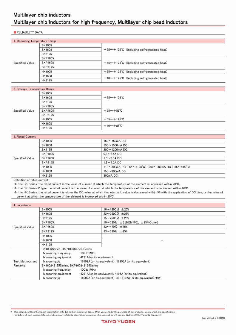
3. Rated Current
Specified Value
BK1005 150~750mA DC
BK1608 150~1500mA DC
BK2125 200~1200mA DC
BKP1005 0.8~2.4A DC
BKP1608 1.0~3.0A DC
BKP2125 1.5~4.0A DC
HK1005 110~300mA DC (-55~+125) 200~900mA DC (-55~+85)
HK1608 150~300mA DC
HK2125 300mA DC
Definition of rated current:
・In the BK Series, the rated current is the value of current at which the temperature of the element is increased within 20.
・In the BK Series P type the rated current is the value of current at which the temperature of the element is increased within 40.
・In the HK Series, the rated current is either the DC value at which the internal L value is decreased within 5% with the application of DC bias, or the value of
current at which the temperature of the element is increased within 20.
4. Impedance
Specified Value
BK1005 10~1800Ω ±25%
BK1608 22~2500Ω ±25%
BK2125 15~2500Ω ±25%
BKP1005 10~330Ω ±5Ω(EM100), ±25%(Other)
BKP1608 33~470Ω ±25%
BKP2125 33~330Ω ±25%
HK1005
- HK1608
HK2125
Test Methods and
Remarks
BK1005Series, BKP1005Series Series
Measuring frequency : 100±1MHz
Measuring equipment : 4291A(or its equivalent)
Measuring jig : 16192A(or its equivalent), 16193A(or its equivalent)
BK1608・2125Series, BKP1608・2125Series
Measuring frequency : 100±1MHz
Measuring equipment : 4291A(or its equivalent), 4195A(or its equivalent)
Measuring jig : 16092A(or its equivalent) or 16192A(or its equivalent)/HW

This catalog contains the typical specification only due to the limitation of space. When you consider the purchase of our products, please check our specification.
For details of each product (characteristics graph, reliability information, precautions for use, and so on), see our Web site (http://www.ty-top.com/) .
hq_i_mlci_reli_e-E02R01
5. Inductance
Specified Value
BK1005
-
BK1608
BK2125
BKP1005
BKP1608
BKP2125
HK1005 1.0~6.2nH: ±0.3nH 6.8~270nH: ±5%
HK1608 1.0~5.6nH: ±0.3nH 6.8~470nH: ±5%
HK2125 1.5~5.6nH: ±0.3nH 6.8~470nH: ±5%
Test Methods and
Remarks
HK Series
Measuring frequency : 100MHz(HK1005)
Measuring frequency : 50/100MHz(HK1608・HK2125)
Measuring equipment /jig : ・4291A+16193A(or its equivalent)/HK1005
・4291A+16092A + in-house made jig(or its equivalent)/HK1608・HK2125
6. Q
Specified Value
BK1005
-
BK1608
BK2125
BKP1005
BKP1608
BKP2125
HK1005 8 min.
HK1608 8~12 min.
HK2125 10~18 min.
Test Methods and
Remarks
HK Series
Measuring frequency : 100MHz(HK1005)
Measuring frequency : 50/100MHz(HK1608・HK2125)
Measuring equipment /jig : ・4291A+16193A(or its equivalent)/HK1005
・4291A+16092A + in-house made jig(or its equivalent)/HK1608, HK2125
7. DC Resistance
Specified Value
BK1005 0.03~0.90Ω max.
BK1608 0.05~1.10Ω max.
BK2125 0.05~0.75Ω max.
BKP1005 0.0273~0.220Ω max.
BKP1608 0.025~0.18Ω max.
BKP2125 0.020~0.075Ω max.
HK1005 0.08~4.8Ω max.
HK1608 0.05~2.6Ω max.
HK2125 0.10~1.5Ω max.
Test Methods and
Remarks Measuring equipment:VOAC-7412, VOAC-7512, VOAC-7521(made by Iwasaki Tsushinki)
8. Self Resonance Frequency(SRF)
Specified Value
BK1005
-
BK1608
BK2125
BKP1005
BKP1608
BKP2125
HK1005 400~10000MHz min.
HK1608 300~10000MHz min.
HK2125 200~4000MHz min.
Test Methods and
Remarks
HK Series :
Measuring equipment : 8719C(or its equivalent)・8753D(or its equivalent)/HK2125

This catalog contains the typical specification only due to the limitation of space. When you consider the purchase of our products, please check our specification.
For details of each product (characteristics graph, reliability information, precautions for use, and so on), see our Web site (http://www.ty-top.com/) .
hq_i_mlci_reli_e-E02R01
9. Temperature Characteristic
Specified Value
BK1005
-
BK1608
BK2125
BKP1005
BKP1608
BKP2125
HK1005
Inductance change:Within ±10% HK1608
HK2125
Test Methods and
Remarks
HK Series:
Temperature range : -30~+85
Reference temperature : +20
10. Resistance to Flexure of Substrate
Specified Value
BK1005
No mechanical damage.
BK1608
BK2125
BKP1005
BKP1608
BKP2125
HK1005
HK1608
HK2125
Test Methods and
Remarks
Warp : 2mm(BK Series 、BKP、HK Series)
Testing board : glass epoxy-resin substrate
Thickness : 0.8mm
20
Warp Board
(Unit:mm)
R-230
45 45
Deviation±1
11. Solderability
Specified Value
BKH1005
At least 75% of terminal electrode is covered by new solder.
BK1608
BK2125
BKP1005
BKP1608
BKP2125
HK1005
HK1608
HK2125
Test Methods and
Remarks
Solder temperature :230±5 (JIS Z 3282 H60A or H63A)
Solder temperature :245±3 (Sn/3.0Ag/0.5Cu)
Duration :4±1 sec.
12. Resistance to Soldering
Specified Value
BK1005
Appearance:No significant abnormality
Impedance change:Within ±30%
BK1608
BK2125
BKP1005
BKP1608
BKP2125
HK1005 No mechanical damage.
Remaining terminal electrode:70% min.
Inductance change: Within ±5%
HK1608
HK2125
Test Methods and
Remarks
Solder temperature :260±5
Duration :10±0.5 sec.
Preheating temperature :150 to 180
Preheating time :3 min.
Flux :Immersion into methanol solution with colophony for 3 to 5 sec.
Recovery :2 to 3 hrs of recovery under the standard condition after the test.(See Note 1)

This catalog contains the typical specification only due to the limitation of space. When you consider the purchase of our products, please check our specification.
For details of each product (characteristics graph, reliability information, precautions for use, and so on), see our Web site (http://www.ty-top.com/) .
hq_i_mlci_reli_e-E02R01
13. Thermal Shock
Specified Value
BK1005
Appearance:No significant abnormality
Impedance change: Within ±30%
BK1608
BK2125
BKP1005
BKP1608
BKP2125
HK1005 No mechanical damage.
Inductance change: Within ±10% Q change: Within ±20% HK1608
HK2125
Test Methods and
Remarks
Conditions for 1 cycle
Step temperature() time(min.)
1 Minimum operating temperature +0/-3 30±3
2 Room temperature 2~3
3 Maximum operating temperature +3/-0 30±3
4 Room temperature 2~3
Number of cycles:5
Recovery:2 to 3 hrs of recovery under the standard condition after the test.(See Note 1)
(Note 1) When there are questions concerning measurement result;measurement shall be made after 48±2 hrs of recovery under the standard condition.
14. Damp Heat( Steady state)
Specified Value
BK1005
Appearance:No significant abnormality
Impedance change: Within ±30%
BK1608
BK2125
BKP1005
BKP1608
BKP2125
HK1005 No mechanical damage.
Inductance change: Within ±10% Q change: Within ±20% HK1608
HK2125
Test Methods and
Remarks
BK、BKP Series:
Temperature :40±2
Humidity :90 to 95%RH
Duration :500+24/-0 hrs
Recovery :2 to 3 hrs of recovery under the standard condition after the removal from test chamber.(See Note 1)
HK Series:
Temperature :60±2( HK Series)
Humidity :90 to 95%RH
Duration :500±12 hrs
Recovery :2 to 3 hrs of recovery under the standard condition after the removal from test chamber.(See Note 1)
15. Loading under Damp Heat
Specified Value
BK1005
Appearance:No significant abnormality
Impedance change: Within ±30%
BK1608
BK2125
BKP1005
BKP1608
BKP2125
HK1005 No mechanical damage.
Inductance change: Within ±10% Q change: Within ±20% HK1608
HK2125
Test Methods and
Remarks
BK、BKP Series:
Temperature :40±2
Humidity :90 to 95%RH
Applied current :Rated current
Duration :500+24/-0 hrs
Recovery :2 to 3 hrs of recovery under the standard condition after the removal from test chamber.(See Note 1)
HK Series:
Temperature :60±2( HK Series)
Humidity :90 to 95%RH
Applied current :Rated current
Duration :500±12 hrs
Recovery :2 to 3 hrs of recovery under the standard condition after the removal from test chamber.(See Note 1)
Note on standard condition: "standard condition" referred to herein is defined as follows:
5 to 35 of temperature, 45 to 85% relative humidity, and 86 to 106kPa of air pressure.
When there are questions concerning measurement results:
In order to provide correlation data, the test shall be conducted under condition of 20±2 of temperature, 60 to 70% relative humidity, and 86 to 106kPa of air
pressure.
Unless otherwise specified, all the tests are conducted under the "standard condition."
(Note 1) Measurement shall be made after 48±2 hrs of recovery under the standard condition.

This catalog contains the typical specification only due to the limitation of space. When you consider the purchase of our products, please check our specification.
For details of each product (characteristics graph, reliability information, precautions for use, and so on), see our Web site (http://www.ty-top.com/) .
hq_i_mlci_reli_e-E02R01
16. Loading at High Temperature
Specified Value
BK1005
Appearance:No significant abnormality
Impedance change: Within ±30%
BK1608
BK2125
BKP1005
BKP1608
BKP2125
HK1005 No mechanical damage.
Inductance change: Within ±10% Q change: Within ±20% HK1608
HK2125
Test Methods and
Remarks
BK、BKP Series:
Temperature : 125±3(BK Series)
: 85±3(BKP Series)
Applied current :Rated current
Duration :500+24/-0 hrs
Recovery :2 to 3 hrs of recovery under the standard condition after the removal from test chamber.
(See Note 1)
HK Series:
Temperature : 85±2(HK1608,2125)
: 85±2(HK1005: operating temperature range-55~+85)
: 125±2(HK1005:operating temperature range-55~+125)
Applied current :Rated current
Duration :500±12 hrs
Recovery :2 to 3 hrs of recovery under the standard condition after the test.(See Note 1)
Note on standard condition: "standard condition" referred to herein is defined as follows:
5 to 35 of temperature, 45 to 85% relative humidity, and 86 to 106kPa of air pressure.
When there are questions concerning measurement results:
In order to provide correlation data, the test shall be conducted under condition of 20±2 of temperature, 60 to 70% relative humidity, and 86 to 106kPa of air
pressure. Unless otherwise specified, all the tests are conducted under the "standard condition."
(Note 1) Measurement shall be made after 48±2 hrs of recovery under the standard condition.

This catalog contains the typical specification only due to the limitation of space. When you consider the purchase of our products, please check our specification.
For details of each product (characteristics graph, reliability information, precautions for use, and so on), see our Web site (http://www.ty-top.com/) .
hq_i_mlci_prec_e-E02R01
Precautions on the use of Multilayer chip inductors
Multilayer chip inductors for high frequency, Multilayer chip bead inductors
PRECAUTIONS
1. Circuit Design
Precautions
Verification of operating environment, electrical rating and performance
1. A malfunction in medical equipment, spacecraft, nuclear reactors, etc. may cause serious harm to human life or have severe social
ramifications.
As such, any inductors to be used in such equipment may require higher safety and/or reliability considerations and should be clearly
differentiated from components used in general purpose applications.
Operating Current(Verification of Rated current)
1. The operating current for inductors must always be lower than their rated values.
2. Do not apply current in excess of the rated value because the inductance may be reduced due to the magnetic saturation effect.
2. PCB Design
Precautions
Pattern configurations(Design of Land-patterns)
1. When inductors are mounted on a PCB, the size of land patterns and the amount of solder used(size of fillet)can directly affect inductor
performance.
Therefore, the following items must be carefully considered in the design of solder land patterns:
(1) The amount of solder applied can affect the ability of chips to withstand mechanical stresses which may lead to breaking or
cracking. Therefore, when designing land-patterns it is necessary to consider the appropriate size and configuration of the solder
pads which in turn determines the amount of solder necessary to form the fillets.
(2) When more than one part is jointly soldered onto the same land or pad, the pad must be designed so that each component's
soldering point is separated by solder-resist.
(3) The larger size of land patterns and amount of solder, the smaller Q value after mounting on PCB. It makes higher the Q value to
design land patterns smaller than terminal electrode of chips.
Pattern configurations(Inductor layout on panelized[ breakaway] PC boards)
1. After inductors have been mounted on the boards, chips can be subjected to mechanical stresses in subsequent manufacturing
processes (PCB cutting, board inspection, mounting of additional parts, assembly into the chassis, wave soldering the reflow soldered
boards etc.)For this reason, planning pattern configurations and the position of SMD inductors should be carefully performed to
minimize stress.
Technical
considerations
Pattern configurations(Design of Land-patterns)
1. The following diagrams and tables show some examples of recommended patterns to prevent excessive solder amounts(larger fillets
which extend above the component end terminations). Examples of improper pattern designs are also shown.
(1) Recommended land dimensions for a typical chip inductor land patterns for PCBs
C
B A B
Chip inductor
Land pattern
Solder-resist
L
W
Chip inductor
Recommended land dimensions for wave-soldering (Unit:mm)
Type 1608 2125
Size L 1.6 2.0
W 0.8 1.25
A 0.8~1.0 1.0~1.4
B 0.5~0.8 0.8~1.5
C 0.6~0.8 0.9~1.2
Recommended land dimensions for reflow-soldering (Unit:mm)
Type 1005 1608 2125
Size L 1.0 2.0 1.6
W 0.5 1.25 0.8
A 0.45~0.55 0.8~1.0 0.8~1.2
B 0.40~0.50 0.6~0.8 0.8~1.2
C 0.45~0.55 0.6~0.8 0.9~1.6
Excess solder can affect the ability of chips to withstand mechanical stresses. Therefore, please take proper precautions when designing
land-patterns.

This catalog contains the typical specification only due to the limitation of space. When you consider the purchase of our products, please check our specification.
For details of each product (characteristics graph, reliability information, precautions for use, and so on), see our Web site (http://www.ty-top.com/) .
hq_i_mlci_prec_e-E02R01
(2) Examples of good and bad solder application
Item Not recommended Recommended
Mixed mounting of SMD and
leaded components
Lead wire of component Solder-resist
Component placement close to
the chassis
Chassis
Solder (for grounding)
Electrode pattern
Solder-resist
Hand-soldering of leaded
components near mounted
components
Soldering iron
Lead wire of component
Solder-resist
Horizontal component
placement
Solder-resist
Pattern configurations(Inductor layout on panelized[ breakaway] PC boards)
1-1. The following are examples of good and bad inductor layout; SMD inductors should be located to minimize any possible mechanical
stresses from board warp or deflection.
Item Not recommended Recommended
Deflection of the board
Position the component at a
right angle to the direction of
the mechanical stresses that
are anticipated.
1-2. To layout the inductors for the breakaway PC board, it should be noted that the amount of mechanical stresses given will vary
depending on inductor layout.
An example below should be counted for better design.
E
D
C
A B
Slit
Magnitude of stress A>B=C>D>E
Perforation
1-3. When breaking PC boards along their perforations, the amount of mechanical stress on the inductors can vary according to the
method used. The following methods are listed in order from least stressful to most stressful: push-back, slit, V-grooving, and
perforation. Thus, any ideal SMD inductor layout must also consider the PCB splitting procedure.
This catalog contains the typical specification only due to the limitation of space. When you consider the purchase of our products, please check our specification.
For details of each product (characteristics graph, reliability information, precautions for use, and so on), see our Web site (http://www.ty-top.com/) .
hq_i_mlci_prec_e-E02R01
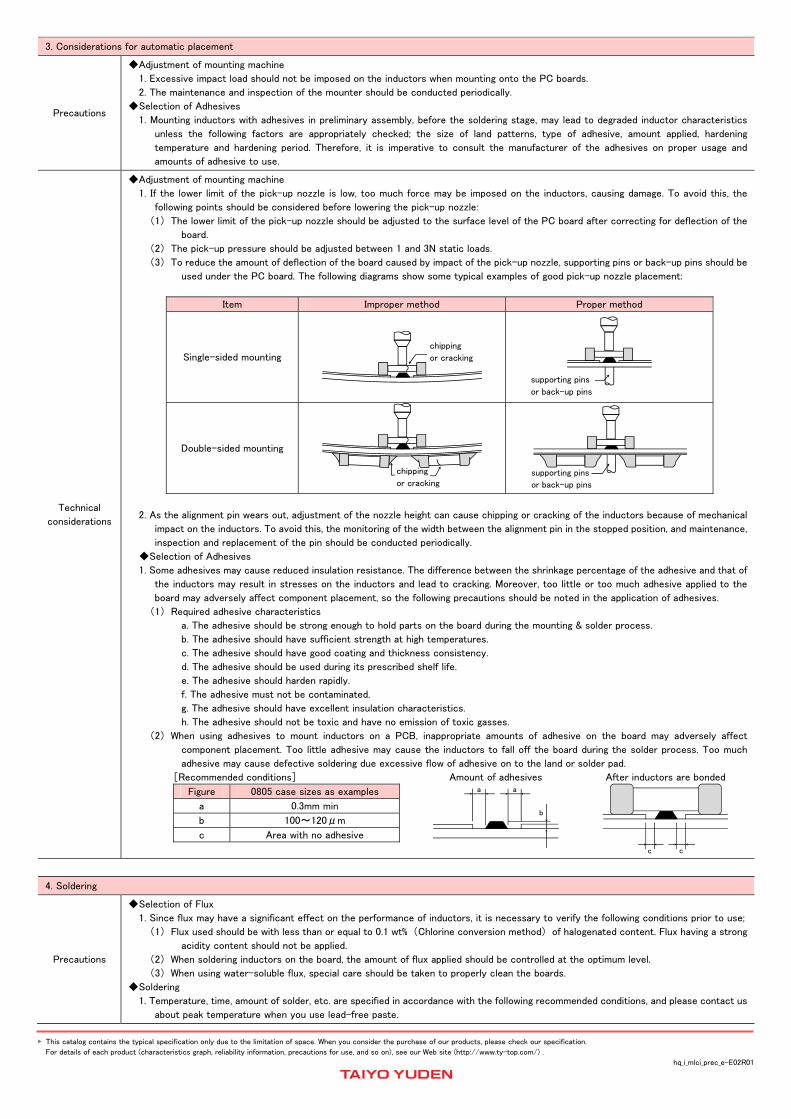
3. Considerations for automatic placement
Precautions
Adjustment of mounting machine
1. Excessive impact load should not be imposed on the inductors when mounting onto the PC boards.
2. The maintenance and inspection of the mounter should be conducted periodically.
Selection of Adhesives
1. Mounting inductors with adhesives in preliminary assembly, before the soldering stage, may lead to degraded inductor characteristics
unless the following factors are appropriately checked; the size of land patterns, type of adhesive, amount applied, hardening
temperature and hardening period. Therefore, it is imperative to consult the manufacturer of the adhesives on proper usage and
amounts of adhesive to use.
Technical
considerations
Adjustment of mounting machine
1. If the lower limit of the pick-up nozzle is low, too much force may be imposed on the inductors, causing damage. To avoid this, the
following points should be considered before lowering the pick-up nozzle:
(1) The lower limit of the pick-up nozzle should be adjusted to the surface level of the PC board after correcting for deflection of the
board.
(2) The pick-up pressure should be adjusted between 1 and 3N static loads.
(3) To reduce the amount of deflection of the board caused by impact of the pick-up nozzle, supporting pins or back-up pins should be
used under the PC board. The following diagrams show some typical examples of good pick-up nozzle placement:
Item Improper method Proper method
Single-sided mounting
chipping
or cracking
supporting pins
or back-up pins
Double-sided mounting
chipping
or cracking supporting pins
or back-up pins
2. As the alignment pin wears out, adjustment of the nozzle height can cause chipping or cracking of the inductors because of mechanical
impact on the inductors. To avoid this, the monitoring of the width between the alignment pin in the stopped position, and maintenance,
inspection and replacement of the pin should be conducted periodically.
Selection of Adhesives
1. Some adhesives may cause reduced insulation resistance. The difference between the shrinkage percentage of the adhesive and that of
the inductors may result in stresses on the inductors and lead to cracking. Moreover, too little or too much adhesive applied to the
board may adversely affect component placement, so the following precautions should be noted in the application of adhesives.
(1) Required adhesive characteristics
a. The adhesive should be strong enough to hold parts on the board during the mounting & solder process.
b. The adhesive should have sufficient strength at high temperatures.
c. The adhesive should have good coating and thickness consistency.
d. The adhesive should be used during its prescribed shelf life.
e. The adhesive should harden rapidly.
f. The adhesive must not be contaminated.
g. The adhesive should have excellent insulation characteristics.
h. The adhesive should not be toxic and have no emission of toxic gasses.
(2) When using adhesives to mount inductors on a PCB, inappropriate amounts of adhesive on the board may adversely affect
component placement. Too little adhesive may cause the inductors to fall off the board during the solder process. Too much
adhesive may cause defective soldering due excessive flow of adhesive on to the land or solder pad.
[Recommended conditions]
Figure 0805 case sizes as examples
a 0.3mm min
b 100~120μm
c Area with no adhesive
Amount of adhesives
a a
b
After inductors are bonded
c c
4. Soldering
Precautions
Selection of Flux
1. Since flux may have a significant effect on the performance of inductors, it is necessary to verify the following conditions prior to use;
(1) Flux used should be with less than or equal to 0.1 wt% (Chlorine conversion method) of halogenated content. Flux having a strong
acidity content should not be applied.
(2) When soldering inductors on the board, the amount of flux applied should be controlled at the optimum level.
(3) When using water-soluble flux, special care should be taken to properly clean the boards.
Soldering
1. Temperature, time, amount of solder, etc. are specified in accordance with the following recommended conditions, and please contact us
about peak temperature when you use lead-free paste.
This catalog contains the typical specification only due to the limitation of space. When you consider the purchase of our products, please check our specification.
For details of each product (characteristics graph, reliability information, precautions for use, and so on), see our Web site (http://www.ty-top.com/) .
hq_i_mlci_prec_e-E02R01
Technical
considerations
Selection of Flux
1-1. When too much halogenated substance(Chlorine, etc.)content is used to activate the flux, or highly acidic flux is used, an excessive
amount of residue after soldering may lead to corrosion of the terminal electrodes or degradation of insulation resistance on the
surface of the Inductor.
1-2. Flux is used to increase solderability in flow soldering, but if too much is applied, a large amount of flux gas may be emitted and may
detrimentally affect solderability. To minimize the amount of flux applied, it is recommended to use a flux-bubbling system.
1-3. Since the residue of water-soluble flux is easily dissolved by water content in the air, the residue on the surface of Inductor in high
humidity conditions may cause a degradation of insulation resistance and therefore affect the reliability of the components. The
cleaning methods and the capability of the machines used should also be considered carefully when selecting water-soluble flux.
Soldering
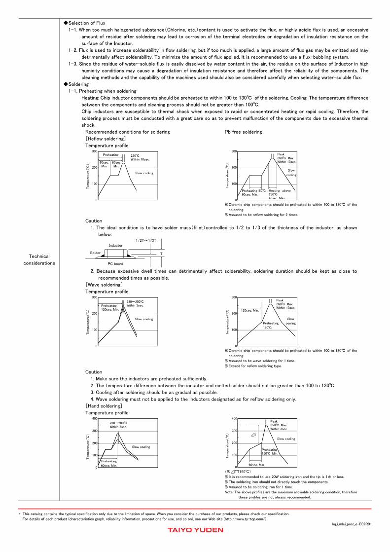
1-1. Preheating when soldering
Heating: Chip inductor components should be preheated to within 100 to 130 of the soldering. Cooling: The temperature difference
between the components and cleaning process should not be greater than 100.
Chip inductors are susceptible to thermal shock when exposed to rapid or concentrated heating or rapid cooling. Therefore, the
soldering process must be conducted with a great care so as to prevent malfunction of the components due to excessive thermal
shock.
Recommended conditions for soldering Pb free soldering
[Reflow soldering]
Temperature profile
Preheating 230 Within 10sec.
Slow cooling
60sec. Min.
60secMin.
300
200
100
0
Tem
pera
ture
()
Peak 260 Max. Within 10sec.
Slow
cooling
Heating above230 40sec. Max.
300
200
100
0
Tem
pera
ture
(
)
Preheating15060sec. Min.
※Ceramic chip components should be preheated to within 100 to 130 of the
soldering.
※Assured to be reflow soldering for 2 times. Caution
1. The ideal condition is to have solder mass(fillet)controlled to 1/2 to 1/3 of the thickness of the inductor, as shown
below:
1/2T~1/3T
PC board
Solder
Inductor
T
2. Because excessive dwell times can detrimentally affect solderability, soldering duration should be kept as close to
recommended times as possible.
[Wave soldering]
Temperature profile
230~250 Within 3sec.
Slow cooling
Preheating 120sec. Min.
300
200
100
0
Tem
pera
ture
()
Peak 260 Max. Within 10sec.
Slow
cooling
120sec. Min.
300
200
100
0
Tem
pera
ture
(
)
Preheating
150
※Ceramic chip components should be preheated to within 100 to 130 of the
soldering.
※Assured to be wave soldering for 1 time.
※Except for reflow soldering type. Caution
1. Make sure the inductors are preheated sufficiently.
2. The temperature difference between the inductor and melted solder should not be greater than 100 to 130.
3. Cooling after soldering should be as gradual as possible.
4. Wave soldering must not be applied to the inductors designated as for reflow soldering only.
[Hand soldering]
Temperature profile
230~280 Within 3sec.
Slow cooling
Preheating
60sec. Min.
400
200
100
0
Tem
pera
ture
(
)
300
Peak 350 Max. Within 3sec.
Slow cooling ⊿T
400
200
100
0
Tem
pera
ture
(
)
Preheating 150 Min.
60sec. Min.
300
(※⊿TT190)
※It is recommended to use 20W soldering iron and the tip is 1φ or less.
※The soldering iron should not directly touch the components.
※Assured to be soldering iron for 1 time.
Note: The above profiles are the maximum allowable soldering condition, therefore
these profiles are not always recommended.
This catalog contains the typical specification only due to the limitation of space. When you consider the purchase of our products, please check our specification.
For details of each product (characteristics graph, reliability information, precautions for use, and so on), see our Web site (http://www.ty-top.com/) .
hq_i_mlci_prec_e-E02R01
Caution
1. Use a 20W soldering iron with a maximum tip diameter of 1.0 mm.
2. The soldering iron should not directly touch the inductor.
5. Cleaning
Precautions
Cleaning conditions
1. When cleaning the PC board after the Inductors are all mounted, select the appropriate cleaning solution according to the type of flux
used and purpose of the cleaning(e.g. to remove soldering flux or other materials from the production process.)
2. Cleaning conditions should be determined after verifying, through a test run, that the cleaning process does not affect the inductor's
characteristics.
Technical
considerations
Cleaning conditions
1. The use of inappropriate solutions can cause foreign substances such as flux residue to adhere to the inductor, resulting in a degradation
of the inductor's electrical properties(especially insulation resistance).
2. Inappropriate cleaning conditions(insufficient or excessive cleaning)may detrimentally affect the performance of the inductors.
(1) Excessive cleaning
a. In the case of ultrasonic cleaning, too much power output can cause excessive vibration of the PC board which may lead to the
cracking of the inductor or the soldered portion, or decrease the terminal electrodes' strength. Thus the following conditions
should be carefully checked;
Ultrasonic output Below 20W/ℓ
Ultrasonic frequency Below 40kHz
Ultrasonic washing period 5 min. or less
6. Post cleaning processes
Precautions
Application of resin coatings, moldings, etc. to the PCB and components.
1. With some type of resins a decomposition gas or chemical reaction vapor may remain inside the resin during the hardening period or while
left under normal storage conditions resulting in the deterioration of the inductor's performance.
2. When a resin's hardening temperature is higher than the inductor's operating temperature, the stresses generated by the excess heat
may lead to inductor damage or destruction.
3. Stress caused by a resin's temperature generated expansion and contraction may damage inductors.
The use of such resins, molding materials etc. is not recommended.
7. Handling
Precautions
Breakaway PC boards(splitting along perforations)
1. When splitting the PC board after mounting inductors and other components, care is required so as not to give any stresses of deflection
or twisting to the board.
2. Board separation should not be done manually, but by using the appropriate devices.
General handling precautions
1. Always wear static control bands to protect against ESD.
2. Keep the inductors away from all magnets and magnetic objects.
3. Use non-magnetic tweezers when handling inductors.
4. Any devices used with the inductors( soldering irons, measuring instruments) should be properly grounded.
5. Keep bare hands and metal products(i.e., metal desk)away from chip electrodes or conductive areas that lead to chip electrodes.
6. Keep inductors away from items that generate magnetic fields such as speakers or coils.
Mechanical considerations
1. Be careful not to subject the inductors to excessive mechanical shocks.
(1) If inductors are dropped on the floor or a hard surface they should not be used.
(2) When handling the mounted boards, be careful that the mounted components do not come in contact with or bump against other
boards or components.
8. Storage conditions
Precautions
Storage
1. To maintain the solderability of terminal electrodes and to keep the packaging material in good condition, care must be taken to control
temperature and humidity in the storage area. Humidity should especially be kept as low as possible.
Recommended conditions
Ambient temperature Below 40
Humidity Below 70% RH
The ambient temperature must be kept below 30. Even under ideal storage conditions inductor electrode solderability decreases as
time passes, so inductors should be used within 6 months from the time of delivery.
*The packaging material should be kept where no chlorine or sulfur exists in the air.
Technical
considerations
Storage
1. If the parts are stocked in a high temperature and humidity environment, problems such as reduced solderability caused by oxidation of
terminal electrodes and deterioration of taping/packaging materials may take place. For this reason, components should be used within
6 months from the time of delivery. If exceeding the above period, please check solderability before using the inductors.