remote control method for mobile robot based on force
TRANSCRIPT
IEEJ Journal of Industry ApplicationsVol.8 No.4 pp.727–735 DOI: 10.1541/ieejjia.8.727
Paper
Remote Control Method for Mobile Robot Based on Force FeedbackGenerated using Collision Prediction Map
Naoki Motoi∗ Senior Member, Masato Kobayashi∗ Student Member
Ryo Masaki∗ Student Member
(Manuscript received Aug. 1, 2018, revised Dec. 12, 2018)
This paper proposes a remote control method for a mobile robot based on the force feedback generated using a colli-sion prediction map. The collision prediction map expresses the relation between the mobile robot and its surroundingenvironment as the collision prediction time at each translational and angular velocity. The force feedback is generatedby using this collision prediction map. In the proposed method, the operator can feel the environmental information asthe tactile sensation. This improves the operability of the remote control system. The validity of the proposed methodwas confirmed from the experimental results.
Keywords: motion control, mobile robot, remote control, force feedback
1. Introduction
Japan has faced many natural disasters such as earthquakesand tsunami. From this background, several disaster defensesystems by using robotics technology have been developed.Mobile robots to collect the environmental information in thedisaster sites are treated as one of these systems (1) (2). There-fore, researches on mobile robots have been actively reported.
Focused on the researches on mobile robots, the controlmethods are roughly classified into two types; One is the au-tonomous control type, and the other is the remote controltype. The autonomous mobile robots have achieved intelli-gent tasks by using several sensor information (3) (4). This tech-nology is useful for the contribution of the labor force, sinceit is possible to conduct tasks without operators. Abbas etal. proposed the obstacle avoidance with the nonlinear modelpredictive control of the autonomous vehicle (5). Lee et al. de-veloped the efficient simultaneous localization and mapping(SLAM) using a monocular vision sensor for indoor servicerobots (6). Hirose et al. reported the following control ap-proach based on the model predictive control (7). However, itis hard for these mobile robots to be applied in the compli-cated environment such as the disaster site.
On the other hand, there are also a lot of researches onremote control of mobile robots. By the assistance basedon the operator’s judgement, remote control systems canachieve several tasks in the complicated environment. Okuraet al. proposed the free-viewpoint mobile robot teleopera-tion based on the vision sensor (8). Zhao et al. developed thebrain-machine interfacing-based teleoperation for the mobilerobots (9). Frank et al. reported the mobile mixed-reality ap-proach to interact with and control a multi-robot system (10).However, it is hard to recognize surrounding environment by
∗ Graduate School of Maritime Sciences, Kobe University5-1-1, Fukaeminami, Higashinada-ku, Kobe 658-0022, Japan
using the only visual information. Therefore, the operatorneeds training for the skillful operation.
For the operability improvement, the remote control meth-ods with the force feedback have been reported. In these con-trol methods, the operator recognizes the surrounding envi-ronment by not only the visual information but also the tac-tile information (11) (12). Pecka et al. reported the tactile terrainexploration by using the mobile robot for traversing roughterrains (13). Xu et al. presents the visual-haptic aid teleop-eration system (14). Ma and Ben-Tzvi developed the teleop-eration with the haptic glove for the mobile robot naviga-tion (15). Masone et al. proposed the shared framework forthe trajectory planning via the force-feedback haptic inter-face for the mobile robots (16). However, most of these con-ventional methods do not consider the non-holonomic con-straint. Therefore, the force commands that mobile robotsdo not realize may be generated. As a result, the operabil-ity of the remote control may not be improved. Consideringthe non-holonomic constraint, we proposed the force com-mand generation method based on the translational and an-gular velocity dimension (17) (18). This research showed the im-proper force feedback did not improve the operability. Onthe other hand, the operability improvement was experimen-tally shown by using the proper force feedback at appropriatetiming (18).
This paper focuses on the remote control method for themobile robot with the force feedback. As with the meth-ods (17) (18), the force commands are generated based on thetranslational and angular velocity dimension. This paper pro-poses the collision prediction map which is calculated fromthe prediction trajectory and the environmental information.This map expresses the collision probability on several trans-lational and angular velocities. By using this collision pre-diction map and the velocity commands, the force feedbackdepending on the collision probability is achieved. As a re-sult, the operator can feel the environmental information as
c© 2019 The Institute of Electrical Engineers of Japan. 727

Remote Control for Mobile Robot with Force Feedback(Naoki Motoi et al.)
Fig. 1. Coordinate Systems
the tactile sensation. Therefore, the operability for the remotecontrol is improved. The validity of the proposed method wasconfirmed from the experimental results.
This paper is organized as follows. Section 2 describes themodeling of the mobile robot. In section 3, the remote con-trol system with the force feedback is explained. Sections 4and 5 describe the generation method of force commands asthe conventional and proposed methods. In section 6, exper-imental results are shown to confirm the validity of the pro-posed remote control system. Finally, this paper is concludedin section 7.
2. Modeling
This section explains the modeling of the mobile robot.Figure 1 shows the coordinate systems. As shown in Fig. 1,the global coordinate system ΣGL and the local coordinatesystem ΣLC are defined. The origin of the global coordinatesystem is constant, and is defined as the center point of therobot at the initial position. On the other hand, the origin ofthe local coordinate system is set to the center point of therobot, and is changed during the moving. The directions ofX-axis and Y-axis are defined as the same direction as thetranslational motion, and the vertical left direction of X-axis.
The relation between the velocities in the global coordinatesystem and these in the local coordinate system is expressedas follows.
GLx = v cos (GLθ) · · · · · · · · · · · · · · · · · · · · · · · · · · · · · · · (1)GLy = v sin (GLθ) · · · · · · · · · · · · · · · · · · · · · · · · · · · · · · · · (2)GLθ = ω · · · · · · · · · · · · · · · · · · · · · · · · · · · · · · · · · · · · · · · · (3)
where x, y and θ represent the positon and posture of the mo-bile robot. The superscript GL means the value in the globalcoordinate system. On the other hand, the values in the localcoordinate system do not use the superscript. v and ω standfor the translational and angular velocities.
3. Remote Control System
This section shows the remote control system for the mo-bile robot. Figure 2 shows the remote control system with theforce feedback. This remote control system consists of themobile robot and two motors as the control device. Two PCsare utilized to control the mobile robot and the control device.As the laser range finder, URG manufactured by HOKUYOAUTOMATIC CO., LTD. is used (19). URG was attached tothe mobile robot to measure the environmental information.3.1 Velocity Commands This subsection describes
the generation of velocity commands. One linear motor is
Fig. 2. Remote Control System with Force Feedback
used for the translational velocity command, and one rotarymotor is utilized for the angular velocity command. Thetranslational velocity command vcmd and the angular veloc-ity command ωcmd are generated in proportional to the move-ment of each motor.
vcmd = Vmax · xresv /X
max · · · · · · · · · · · · · · · · · · · · · · · · · (4)
ωcmd = Ωmax · θresω /Θ
max · · · · · · · · · · · · · · · · · · · · · · · · (5)
where Vmax and Ωmax represent the maximum values of thetranslational and angular velocities. Xmax and Θmax mean themaximum displacement and maximum rotation angle of mo-tors. These values are decided from the specifications of themobile robot and motors. xres
v and θresω stand for the position
response of linear motor and the angle response of the rotarymotor. The translational and angular velocity commands aresent to the mobile robot by UDP.3.2 Force Controller This subsection shows the
force feedback in the control device. For the accelerationcontrol, disturbance observer (DOB) (21) is implemented ineach motor. In addition, reaction force observer (RFOB) (22) isalso implemented to estimate the reaction force without theforce sensor. The force controller based on the accelerationcontrol is expressed.
xre fv = Kf ( f cmd
v − f extv ) · · · · · · · · · · · · · · · · · · · · · · · · · · (6)
θre fω = Kf ( f cmd
ω − f extω ) · · · · · · · · · · · · · · · · · · · · · · · · · · (7)
where Kf means the force feedback gain. f cmd and f ext rep-resent the force command and reaction force estimated byRFOB. The superscript re f means the reference value. Thesubscripts v and ω stand for the values related to the transla-tional velocity and the angular velocity.
By using (6) and (7), the force commands are realized.Therefore, the operator can feel the force feedback as the tac-tile sensation. On the other hand, it is possible to manipulatethe control device with the small operational force, if forcecommands are equal to 0 ( f cmd = 0). The generation meth-ods of force commands are detailed in sections 4 and 5.
4. Conventional Method
Figure 3 shows the force command generation for theremote control as the conventional method (11) (12). In thismethod, the force command is generated in proportion tothe distance between the obstacle and the mobile robot. Theforce command f cmd is calculated as follows.
728 IEEJ Journal IA, Vol.8, No.4, 2019

Remote Control for Mobile Robot with Force Feedback(Naoki Motoi et al.)
(a) Side View
(b) Top View
Fig. 3. Force Command Generation using GeometricRelation
f cmd =
{Ki · (R0 − R) R0 > R0 otherwise
· · · · · · · · · · · · · · · · (8)
where R and R0 stand for the distance from the mobile robotto the closest environment and the distance threshold. Ki isthe variable feedback gain to generate the force command.As shown in Fig. 3(a), the force command is generated in thecondition of R0 > R.
The feedback gain Ki is modified due to the differentiationof the distance from the mobile robot to the closest environ-ment.
Ki =
⎧⎪⎪⎪⎪⎨⎪⎪⎪⎪⎩Kmin dR
dt ≥01γ(Kmax−Kmin) dR
dt +Kmin −γ < dRdt <0
Kmax dRdt ≤−γ
· · · · · · · · · · · · · · · · · · · · (9)
where Kmax and Kmin mean the maximum and minimum feed-back gains. γ represents the velocity limitation.
In order to achieve this force command, it is necessary todivide the force command into the translational and angulardirections. For this division, the angle between the mobilerobot and closest environment as shown in Fig. 3(b) is uti-lized.
f cmdv = f cmd · sin θenv · · · · · · · · · · · · · · · · · · · · · · · · · · · (10)
f cmdω = f cmd · cos θenv · · · · · · · · · · · · · · · · · · · · · · · · · · · (11)
where θenv represents the angle between the mobile robot andthe closest environment.
5. Proposed Method
This section proposes the force generation method usingthe collision prediction map. Firstly, the collision predictionmap is detailed. Secondly, the force commands are gener-ated by the relation between the collision prediction map andvelocity commands.5.1 Collision Prediction Method This subsection
explains the collision prediction method between the mobilerobot and environment. This collision prediction is used togenerate the force commands. For the collision prediction,dynamic window is calculated (4). Dynamic window is com-posed of the translational and angular velocities which the
mobile robot can realize after the unit time ΔT [s]. The unittime ΔT should be set considering the relation between themaximum/minimum velocities and maximum accelerationsfrom the robot specification. Dynamic window is expressedas follows.
vmaxd = vres + Vmax · ΔT · · · · · · · · · · · · · · · · · · · · · · · · (12)
vmind = vres − Vmax · ΔT · · · · · · · · · · · · · · · · · · · · · · · · · (13)
ωmaxd = ωres + Ωmax · ΔT · · · · · · · · · · · · · · · · · · · · · · · (14)
ωmind = ωres − Ωmax · ΔT · · · · · · · · · · · · · · · · · · · · · · · (15)
where vres and ωres mean the translational and angular ve-locity responses. These velocity responses are treated as thecurrent velocities. The subscript d is the values related todynamic window. The superscripts max and min represent themaximum and minimum values. Vmax and Ωmax stand forthe maximum translational and angular velocities. vmax
d , vmind ,
ωmaxd and ωmin
d are the maximum and minimum values of thetranslational and angular velocities after ΔT [s]. Consideringthe robot specification, dynamic window is modified.
vmaxd =
{Vmax i f vmax
d > Vmax
vmaxd otherwise
· · · · · · · · · · · · · · · · (16)
vmind =
{Vmin i f vmin
d < Vmin
vmind otherwise
· · · · · · · · · · · · · · · · · · (17)
ωmaxd =
{Ωmax i f ωmax
d > Ωmax
ωmaxd otherwise
· · · · · · · · · · · · · · · (18)
ωmind =
{Ωmin i f ωmin
d < Ωmin
ωmaxd otherwise
· · · · · · · · · · · · · · · · (19)
where Vmin andΩmin mean the minimum translational and an-gular velocities from the robot specification. In this research,the minimum translational velocity is equal to 0 (Vmin = 0).In other words, this research focuses on the forward motion.Dynamic window is expressed as the velocity area from vmin
dto vmax
d and from ωmind to ωmax
d .In order to calculate the collision prediction, dynamic win-
dow is divided into N along the translational velocity and Malong the angular velocity. N and M are natural numbers andare defined as follows.
N =
⎢⎢⎢⎢⎢⎢⎢⎢⎣ vmaxd − vmin
d
ΔV
⎥⎥⎥⎥⎥⎥⎥⎥⎦ · · · · · · · · · · · · · · · · · · · · · · · · · · · · · (20)
M =
⎢⎢⎢⎢⎢⎢⎢⎢⎣ωmaxd − ωmin
d
ΔΩ
⎥⎥⎥⎥⎥⎥⎥⎥⎦ · · · · · · · · · · · · · · · · · · · · · · · · · · · · (21)
where ΔV and ΔΩ represent the resolutions of the transla-tional and angular velocities for the collision prediction. � �means floor function. As a result, dynamic window is di-vided into N × M. The higher the resolutions of velocitiesare, the more precise the collision prediction is calculated.However, the communication time delay between two PCsoccurs, since the calculation cost and the data amount of thecollision prediction are increased. Considering this tradeoff,it is necessary to set resolutions of the translational and an-gular velocities for the collision prediction.
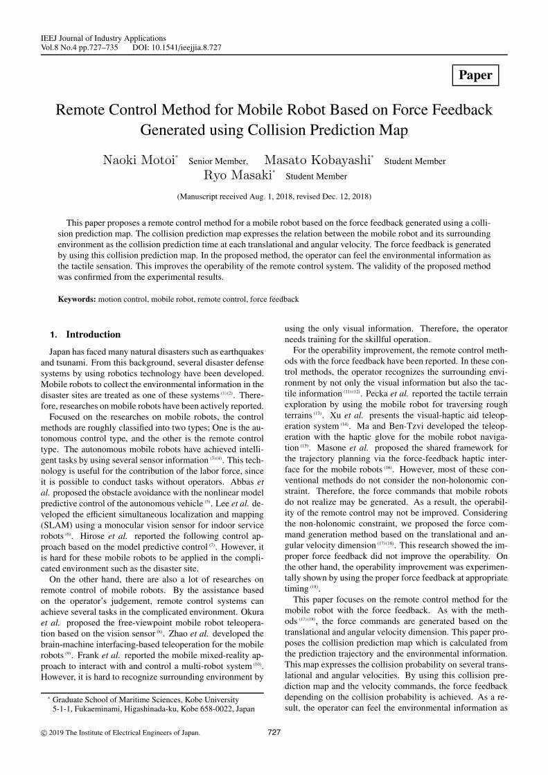
Figure 4 shows the flowchart of the collision prediction be-tween the robot and environment. As shown in Fig. 4, thisflowchart consists of 6 steps.
729 IEEJ Journal IA, Vol.8, No.4, 2019
Remote Control for Mobile Robot with Force Feedback(Naoki Motoi et al.)
Fig. 4. Flowchart for Collision Check
Step 1: Coefficients i(i = 0, 1, 2, · · · ,N) and j( j =0, 1, 2, · · · ,M) are initialized.
i = 0 · · · · · · · · · · · · · · · · · · · · · · · · · · · · · · · · · · · · · · · · · (22)
j = 0 · · · · · · · · · · · · · · · · · · · · · · · · · · · · · · · · · · · · · · · · · (23)
Step 2: The translational velocity for the collision check vi iscalculated.
vi = vmind + i · ΔV · · · · · · · · · · · · · · · · · · · · · · · · · · · · · · · (24)
Step 3: The angular velocity for the collision check ω j is cal-culated.
ω j = ωmind + j · ΔΩ · · · · · · · · · · · · · · · · · · · · · · · · · · · · · (25)
Step 4: The collision check is conducted by using the trans-lational velocity vi, the angular velocity ω j and the environ-mental information measured by URG. The detail of the col-lision check is described in Section 5.2.Step 5: If j is larger than M, go to Step 6. Otherwise, j = j+1and go to Step 3.Step 6: If i is larger than N, this flowchart is finished. Other-wise, i = i + 1, j = 0 and go to Step 2.5.2 Collision Prediction Map This subsection pro-
poses the collision prediction map. Figure 5 shows theflowchart to calculate the collision prediction map. Thisflowchart is inserted in Step 4 of Fig. 4. As shown in Fig. 5,the collision check is conducted.Step 4-1: By the relation between |ω j| and Ωth, the robot mo-tion is divided into 2 cases. Ωth is the threshold value in theangular velocity. In addition, Ωth should be set to the valueclose to 0.Step 4-2A: In the case of |ω j| ≤ Ωth, the robot motion istreated as the straight motion as shown in Fig. 6(a). Theseenvironmental information measured by URG is expressedas (xs
l , ysl )(l = 1, 2, · · · , P). P is the number of measurement
points by URG. By using the prediction trajectory consider-ing the robot width D, the environment where there is thecollision possibility is extracted.
ysl > −
D2· · · · · · · · · · · · · · · · · · · · · · · · · · · · · · · · · · · · · · (26)
ysl <
D2· · · · · · · · · · · · · · · · · · · · · · · · · · · · · · · · · · · · · · · (27)
Fig. 5. Flowchart for Collision Prediction Map
(a) |ω j | ≤ Ωth (b) |ω j | > Ωth
Fig. 6. Calculation of Prediction Collision Time
The closest environment within (26) and (27) is defined as(xs
min, ysmin). The distance from the robot to (xs
min, ysmin) is cal-
culated.
Lsi j = xs
min · · · · · · · · · · · · · · · · · · · · · · · · · · · · · · · · · · · · · · (28)
where Lsi j means the distance to the closest environment from
the robot in the case of vi and ω j.Step 4-2B: In the case of |ω j| > Ωth, the robot motion is
treated as the circular movement. In this case, the turningradius R is calculated from the vi and ω j.
R =viω j· · · · · · · · · · · · · · · · · · · · · · · · · · · · · · · · · · · · · · · · (29)
The center of the rotation is expressed as (0,R) in the localcoordinate system. Therefore, the environment of the highcollision probability is extracted by using the prediction tra-jectory considering the robot width D.
(xsl − 0)2 + (ys
l − R)2 >(R − D
2
)2· · · · · · · · · · · · · · · (30)
(xsl − 0)2 + (ys
l − R)2 <(R +
D2
)2· · · · · · · · · · · · · · · (31)
In (30) and (31), the closest environment to the mobile robotis searched. This closest environment has the highest proba-bility of collision with the robot. The angle between the robotand closest environment is defined as θs
min. The distance fromthe robot to the closest environment is calculated from thecircumference.
Lsi j = Rθs
min · · · · · · · · · · · · · · · · · · · · · · · · · · · · · · · · · · · · (32)
730 IEEJ Journal IA, Vol.8, No.4, 2019

Remote Control for Mobile Robot with Force Feedback(Naoki Motoi et al.)
Step 4-3: The prediction time T ci j to the collision between the
robot and the environment is calculated.
T ci j =
Lsi j
vi· · · · · · · · · · · · · · · · · · · · · · · · · · · · · · · · · · · · · · (33)
In (33), the prediction time in the case of vi and ω j is esti-mated. As shown in Fig. 4, this calculation for the collisionprediction is conducted for N×M sets of translational and an-gular velocities. By using N × M sets of the prediction time,the collision prediction map is obtained.5.3 Generation Method of Force Commands This
subsection proposes the generation method of force com-mands by using the collision prediction map and velocitycommands. The collision prediction map is composed ofthe prediction time calculated from vi and ω j. vi and ω j
are the translational and angular velocities for the collisioncheck, and these values are discrete values. On the otherhand, the velocity commands vcmd and ωcmd are continuesvalues. Therefore, the interpolation using Bezier surface isconducted.
The closest points of the velocity commands in the colli-sion prediction map are calculated as follows.
n =
⎢⎢⎢⎢⎢⎢⎢⎢⎣ vcmd − Vmin
d
ΔV
⎥⎥⎥⎥⎥⎥⎥⎥⎦ · · · · · · · · · · · · · · · · · · · · · · · · · · · · ·(34)
m =
⎢⎢⎢⎢⎢⎢⎢⎢⎣ωcmd −Ωmin
d
ΔΩ
⎥⎥⎥⎥⎥⎥⎥⎥⎦ · · · · · · · · · · · · · · · · · · · · · · · · · · · · ·(35)
where n and m mean the integral numbers. The collision pre-diction time for vcmd and ωcmd is obtained by the interpolationusing Bezier surface. At first, the interpolation along the an-gular velocity is conducted.
tcv(n+k)ωcmd = akω
3p + bkω
2p + ckωp + dk · · · · · · · · · · · · (36)
where ak, bk, ck, dk (k = −1, 0, 1) and ωp are expressed asfollows.
ak =−T c
(n+k)(m+1) + 2T c(n+k)m − T c
(n+k)(m−1)
4ΔΩ3· · · · · · · (37)
bk =3(T c
(n+k)(m+1) − 2T c(n+k)m + T c
(n+k)(m−1))
4ΔΩ2· · · · · · (38)
ck =T c
(n+k)(m+1) − T c(n+k)(m−1)
2ΔΩ· · · · · · · · · · · · · · · · · · · (39)
dk = T c(n+k)m · · · · · · · · · · · · · · · · · · · · · · · · · · · · · · · · · · · (40)
ωp = ωcmd − ωm · · · · · · · · · · · · · · · · · · · · · · · · · · · · · · · (41)
where tcv(n+k)ωcmd means the collision prediction time in the case
of v(n+k) and ωcmd.By using (36), the interpolation along the translational ve-
locity is calculated.
tcvcmdωcmd = ev3p + f v2p + gvp + h · · · · · · · · · · · · · · · · · · · (42)
where e, f , g, h and vp are described as follows.
e =−T c
(n+1)m + 2T cnm − T c
(n−1)m
4ΔV3· · · · · · · · · · · · · · · · · (43)
f =3(T c
(n+1)m − 2T cnm + T c
(n−1)m)
4ΔV2· · · · · · · · · · · · · · · · (44)
g =T c
(n+1)m − T c(n−1)m
2ΔV· · · · · · · · · · · · · · · · · · · · · · · · · · (45)
h = T cnm · · · · · · · · · · · · · · · · · · · · · · · · · · · · · · · · · · · · · · · (46)
vp = vcmd − vn · · · · · · · · · · · · · · · · · · · · · · · · · · · · · · · · · (47)
where tcvcmdωcmd means the collision prediction time in the case
of vcmd and ωcmd.By using the collision prediction time tc
vcmdωcmd , the forcecommands are generated.
f cmd=
{α(tcvcmdωcmd−Tth) i f tc
vcmdωcmd < Tth
0.0 otherwise· · · · · · · (48)
where Tth sands for time threshold. αmeans the coefficient togenerate the force commands. If the collision prediction timetcvcmdωcmd is smaller than time threshold Tth, the collision prob-
ability is high. Therefore, the force commands generated. Inthe case of tc
vcmdωcmd > Tth, the collision probability is low.In this case, the force command is set to 0, and the operatormanipulates the control device with the small manipulationforce.
The coefficient of the force command α should be decidedconsidering the relation between the maximum force of thecontrol device and the time threshold. By setting the timethreshold Tth high, the safety remote control is achieved. Onthe other, the frequent force commands occur depending onthe environment condition such as the narrow space. This fre-quent force commands may not connect the operability im-provement. From this viewpoint, time threshold should bedecided considering the environment condition and the oper-ability of the remote control system.
The control device consists of the linear motor for thetranslational direction and the rotary motor for the angulardirection as shown in Fig. 2. For the realization of the forcefeedback in the control device, it is necessary to divide theforce command into the translational direction and the angu-lar direction. Considering the gradients of the collision pre-diction map with respect to the translational and angular ve-locities, it is possible to recover the collision prediction timeby the force feedback. As a result, the force command is di-vided into the translational direction and the angular directionby the gradient in the collision prediction map.
f cmdv = f cmd Δtv√
Δtv2 + Δtω
2· · · · · · · · · · · · · · · · · · · · · (49)
f cmdω = f cmd Δtω√
Δtv2 + Δtω
2· · · · · · · · · · · · · · · · · · · · · (50)
Δtv =∂tcvcmdωcmd
∂v· · · · · · · · · · · · · · · · · · · · · · · · · · · · · · · · (51)
Δtω =∂tcvcmdωcmd
∂ω· · · · · · · · · · · · · · · · · · · · · · · · · · · · · · · (52)
where Δtv and Δtω mean the gradients with respect to thetranslational and angular velocities. By substituting (49) and(50) for (6) and (7), the operator can feel collision probabilityas the tactile sensation.
6. Experiments
This section confirmed the validity of the proposed methodfrom the experimental results. Firstly, the experimental setupis explained. Secondly, the experimental results are shown.
731 IEEJ Journal IA, Vol.8, No.4, 2019

Remote Control for Mobile Robot with Force Feedback(Naoki Motoi et al.)
Fig. 7. Experimental Course
Table 1. Specification of Mobile Robot
Vmax Maximum translational velocity 0.4 [m/s]Vmin Minimum translational velocity 0.0 [m/s]Ωmax Maximum angular velocity 1.5 [m/s]Ωmin Minimum angular velocity -1.5 [m/s]Vmax Maximum acceleration 1.0 [m/s2]Ωmax Maximum angular acceleration 2.0 [m/s2]D Mobile robot width 0.4 [m]
Table 2. Control ParametersΔT Unit time for prediction map 1.0 [s]ΔV Resolution of translational velocity 0.05 [m/s]ΔΩ Resolution of angular velocity 0.1 [ rad/s]Ωth Angular velocity threshold 0.05 [ rad/s]K f Force feedback gain 1.0
Table 3. Parameters for Force CommandR0 Distance threshold 0.5 [m]Kmin Minimum feedback gain 20.0Kmax Maximum feedback gain 40.0γ Velocity limitation 0.15 [m/s]α Coefficient of force command 6.0Tth Time threshold in Case 1 4.5 [s]Tth Time threshold in Case 2 2.5 [s]
6.1 Experimental Setup This subsection describesthe experimental setup. Figure 2 shows the remote controlsystem which was utilized in this experiment. This mobilerobot is T-frog project i-Cart mini (20). Tables 1–3 show thespecification of the mobile robot, control parameters, and pa-rameters for the force command. The force feedback gainKf , parameters in the conventional method, R0, Kmin, Kmax,and γ are set by the trials and errors in this paper.
The experiments are divided into 2 cases.Case 1: The mobile robot moved along the straight line asshown in Fig. 7. In Case 1, the comparison between the con-ventional method and the proposed method was evaluated.For the evaluation under the same condition, the only con-stant translational velocity command was set (vcmd = 0.15,ωcmd = 0.0). In addition, this experiment did not conduct theforce feedback, but the generation of the force commands.From the difference of the force commands, the validity ofthe force command generation was checked.Case 2: The mobile robot moved along the right turnedcourse as shown in Fig. 7. In Case 2, the proposed methodwas implemented. From this experiment, the validity of theproposed remote control system with the force feedback wasconfirmed.6.2 Experimental Results This subsection shows the
Fig. 8. Trajectory of Mobile Robot (Case 1)
(a) Velocity Commands
(b) Force Commands (Conventional Method)
(c) Force Commands (Proposed Method)
Fig. 9. Experimental Results (Case 1)
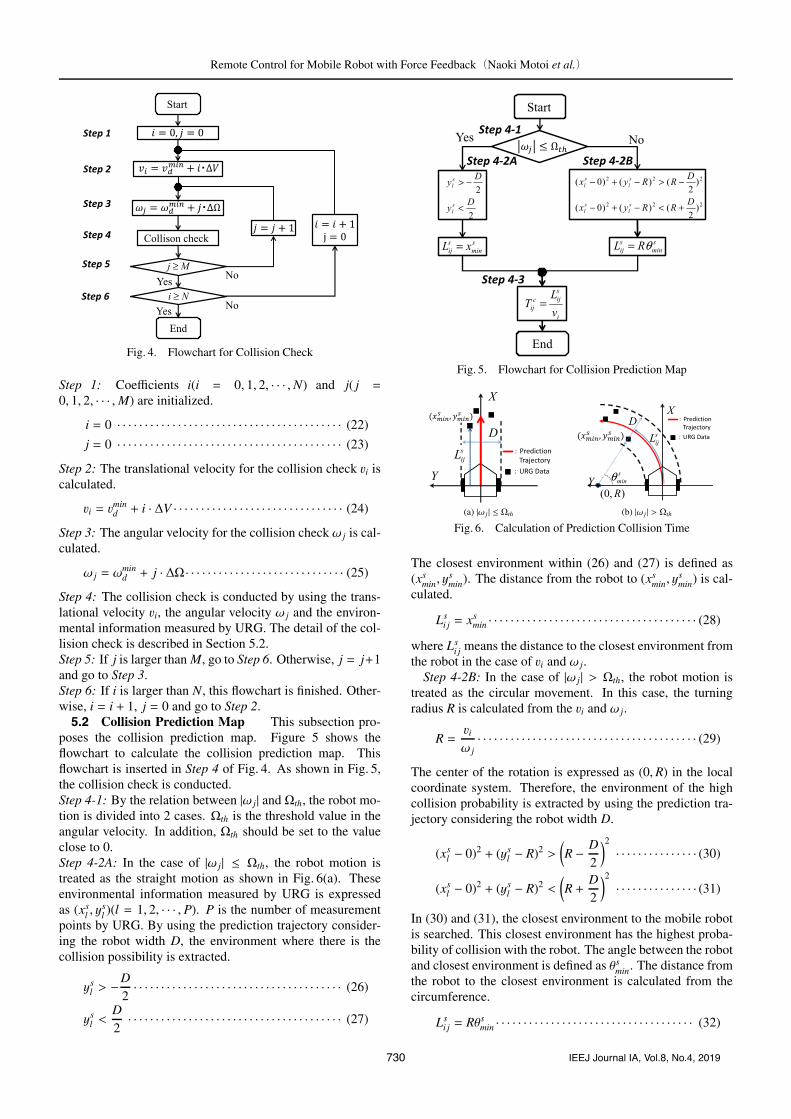
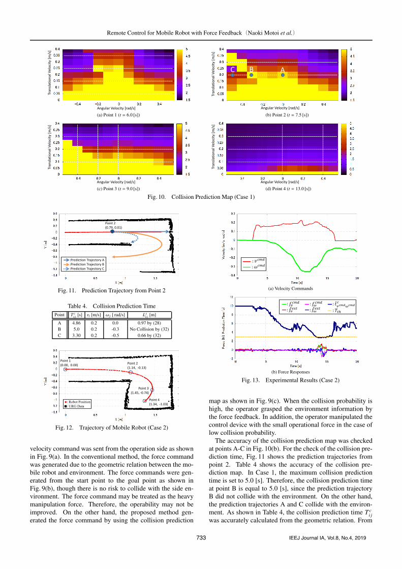
experimental results to confirm the validity of the proposedmethod. Figures 8-9 show the trajectory of the mobile robot,and experimental results in Case 1. In Fig. 8, the robot po-sition was calculated from the odometry information. URGdata was used as the environmental information. As shown inFig. 8, the mobile robot moved along the straight line by theremote operation. Fig. 10 shows the collision prediction mapat points 1-4 shown in Fig. 8. The collision prediction mapwas changed due to the relation between the mobile robotand the environmental information.
Figure 9(a), (b) and (c) represent the velocity commands,the force commands by the conventional method and pro-posed method. In Case 1, the only constant translational
732 IEEJ Journal IA, Vol.8, No.4, 2019
Remote Control for Mobile Robot with Force Feedback(Naoki Motoi et al.)
(a) Point 1 (t = 6.0 [s]) (b) Point 2 (t = 7.5 [s])
(c) Point 3 (t = 9.0 [s]) (d) Point 4 (t = 13.0 [s])
Fig. 10. Collision Prediction Map (Case 1)
Fig. 11. Prediction Trajectory from Point 2
Table 4. Collision Prediction TimePoint T c
i j [s] vi [m/s] ω j [ rad/s] Lsi j [m]
A 4.86 0.2 0.0 0.97 by (28)B 5.0 0.2 -0.3 No Collision by (32)C 3.30 0.2 -0.5 0.66 by (32)
Fig. 12. Trajectory of Mobile Robot (Case 2)
velocity command was sent from the operation side as shownin Fig. 9(a). In the conventional method, the force commandwas generated due to the geometric relation between the mo-bile robot and environment. The force commands were gen-erated from the start point to the goal point as shown inFig. 9(b), though there is no risk to collide with the side en-vironment. The force command may be treated as the heavymanipulation force. Therefore, the operability may not beimproved. On the other hand, the proposed method gen-erated the force command by using the collision prediction
(a) Velocity Commands
(b) Force Responses
Fig. 13. Experimental Results (Case 2)
map as shown in Fig. 9(c). When the collision probability ishigh, the operator grasped the environment information bythe force feedback. In addition, the operator manipulated thecontrol device with the small operational force in the case oflow collision probability.
The accuracy of the collision prediction map was checkedat points A-C in Fig. 10(b). For the check of the collision pre-diction time, Fig. 11 shows the prediction trajectories frompoint 2. Table 4 shows the accuracy of the collision pre-diction map. In Case 1, the maximum collision predictiontime is set to 5.0 [s]. Therefore, the collision prediction timeat point B is equal to 5.0 [s], since the prediction trajectoryB did not collide with the environment. On the other hand,the prediction trajectories A and C collide with the environ-ment. As shown in Table 4, the collision prediction time T c
i jwas accurately calculated from the geometric relation. From
733 IEEJ Journal IA, Vol.8, No.4, 2019
Remote Control for Mobile Robot with Force Feedback(Naoki Motoi et al.)
(a) Point 1 (t = 2.0 [s]) (b) Point 2 (t = 10.0 [s])
(c) Point 3 (t = 14.0 [s]) (d) Point 4 (t = 18.0 [s])
Fig. 14. Collision Prediction Map (Case 2)
these results, the reliability of the collision prediction mapwas confirmed.
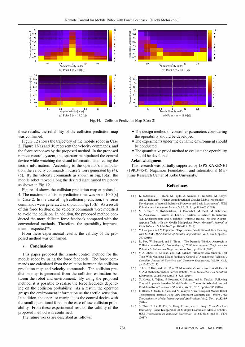
Figure 12 shows the trajectory of the mobile robot in Case2. Figure 13(a) and (b) represent the velocity commands, andthe force responses by the proposed method. In the proposedremote control system, the operator manipulated the controldevice while watching the visual information and feeling thetactile information. According to the operator’s manipula-tion, the velocity commands in Case 2 were generated by (4),(5). By the velocity commands as shown in Fig. 13(a), themobile robot moved along the desired right turned trajectoryas shown in Fig. 12.
Figure 14 shows the collision prediction map at points 1–4. The maximum collision prediction time was set to 10.0 [s]in Case 2. In the case of high collision prediction, the forcecommands were generated as shown in Fig. 13(b). As a resultof this force feedback, the velocity commands were modifiedto avoid the collision. In addition, the proposed method con-ducted the more delicate force feedback compared with theconventional methods. Therefore, the operability improve-ment is expected (18).
From these experimental results, the validity of the pro-posed method was confirmed.
7. Conclusions
This paper proposed the remote control method for themobile robot by using the force feedback. The force com-mands are calculated from the relation between the collisionprediction map and velocity commands. The collision pre-diction map is generated from the collision estimation be-tween the robot and environment. By using the proposedmethod, it is possible to realize the force feedback depend-ing on the collision probability. As a result, the operatorgrasps the environment information as the tactile sensation.In addition, the operator manipulates the control device withthe small operational force in the case of low collision prob-ability. From these experimental results, the validity of theproposed method was confirmed.
The future works are described as follows.
• The design method of controller parameters consideringthe operability should be developed.• The experiments under the dynamic environment should
be conducted.• The quantitative proof method to evaluate the operability
should be developed.AcknowledgmentThis research was partially supported by JSPS KAKENHI
(19K04454), Nagamori Foundation, and International Mar-itime Research Center of Kobe University.
References
( 1 ) K. Tadakuma, E. Takane, M. Fujita, A. Nomura, H. Komatsu, M. Konyo,and S. Tadokoro: “Planar Omnidirectional Crawler Mobile Mechanism—Development of Actual Mechanical Prototype and Basic Experiments”, IEEERobotics and Automation Letters, Vol.3, No.1, pp.395–402 (2018)
( 2 ) M. Schwarz, T. Rodehutskors, D. Droeschel, M. Beul, M. Schreiber,N. Araslanov, I. Ivanov, C. Lenz, J. Razlaw, S. Schller, D. Schwarz,A.T. Kyniazopoulou, and S. Behnke: “NimbRo Rescue: Solving Disaster-response Tasks with the Mobile Manipulator Robot Momaro”, Journal ofField Robotics, Vol.34, No.2, pp.400–425 (2017)
( 3 ) Y. Hasegawa and Y. Fujimoto: “Experimental Verification of Path Planningwith SLAM”, IEEJ Journal of Industry Applications, Vol.5, No.3, pp.253–260 (2016)
( 4 ) D. Fox, W. Burgard, and S. Thrun: “The Dynamic Window Approach toCollision Avoidance”, Proceedings of IEEE International Conference onRobotics & Automation Magazine, Vol.4, No.1, pp.23–33 (2005)
( 5 ) M.A. Abbas, R. Milman, and J.M. Eklund: “Obstacle Avoidance in RealTime With Nonlinear Model Predictive Control of Autonomous Vehicles”,Canadian Journal of Electrical and Computer Engineering, Vol.40, No.1,pp.12–22 (2017)
( 6 ) T. Lee, C. Kim, and D.D. Cho: “A Monocular Vision Sensor-Based EfficientSLAM Method for Indoor Service Robots”, IEEE Transactions on IndustrialElectronics, Vol.66, No.1, pp.318–328 (2019)
( 7 ) N. Hirose, R. Tajima, N. Koyama, K. Sukigara, and M. Tanaka: “FollowingControl Approach Based on Model Predictive Control for Wheeled InvertedPendulum Robot”, Advanced Robotics, Vol.30, No.6, pp.374–385 (2016)
( 8 ) F. Okura, Y. Ueda, T. Sato, and N. Yokoya: “Free-viewpoint Mobile RobotTeleoperation Interface Using View-dependent Geometry and Texture”, ITETransactions on Media Technology and Applications, Vol.2, No.1, pp.82–93(2014)
( 9 ) S. Zhao, Z. Li, R. Cui, Y. Kang, F. Sun, and R. Song: “BrainMachineInterfacing-Based Teleoperation of Multiple Coordinated Mobile Robots”,IEEE Transactions on Industrial Electronics, Vol.64, No.6, pp.5161–5170(2017)
734 IEEJ Journal IA, Vol.8, No.4, 2019

Remote Control for Mobile Robot with Force Feedback(Naoki Motoi et al.)
(10 ) J.A. Frank, S.P. Krishnamoorthy, and V. Kapila: “Toward Mobile Mixed-Reality Interaction With Multi-Robot Systems”, IEEE Robotics and Automa-tion Letters, Vol.2, No.4, pp.1901–1908 (2017)
(11) I. Farkhatdinov, J.H. Ryu, and J. Poduraev: “Rendering of EnvironmentalForce Feedback in Mobile Robot Teleoperation based on Fuzzy Logic”, Pro-ceedings of IEEE International Symposium on Computational Intelligent inRobotics and Automation, pp.503–508 (2009)
(12) I. Farkhatdinov, J.H. Ryu, and J. Poduraev: “A Preliminary Experimen-tal Study on Haptic Teleoperation of Mobile Robot with Variable ForceFeedback Gain”, Proceedings of IEEE International Symposium on Haptics,pp.251–256 (2010)
(13) M. Pecka, K. Zimmermann, M. Reinstein, and T. Svoboda: “ControllingRobot Morphology From Incomplete Measurements”, IEEE Transactions onIndustrial Electronics, Vol.64, No.2, pp.1773–1782 (2017)
(14) X. Xu, A. Song, D. Ni, H. Li, P. Xiong, and C. Zhu: “Visual-Haptic AidTeleoperation Based on 3-D Environment Modeling and Updating”, IEEETransactions on Industrial Electronics, Vol.63, No.10, pp.6419–6428 (2016)
(15) Z. Ma and P. Ben-Tzvi: “RML Glove—An Exoskeleton Glove MechanismWith Haptics Feedback”, IEEE Transactions on Mechatronics, Vol.20, No.2,pp.641–652 (2015)
(16) C. Masone, M. Mohammadi, P.R. Giordano, and A. Franchi: “Shared plan-ning and control for mobile robots with integral haptic feedback”, The Inter-national Journal of Robotics Research, Vol.37, No.11, pp.1395–1420 (2018)
(17) N. Motoi and H. Kimura: “Remote Control Method for Mobile Robot withVirtual Force Feedback Based on Environmental Information”, Proceedingsof IEEJ International Workshop on Sensing, Actuation, and Motion Control,IS3-3, pp.1–6 (2016)
(18) N. Motoi, H. Kimura, and M. Kobayashi: “Experimental Operability Evalu-ation of Remote Control with Force Feedback for Mobile Robot”, Proceed-ings of IEEE International Conference on Industrial Technology, pp.159–164(2018)
(19) HOKUYO AUTOMATIC CO., LTD., http://www.hokuyo-aut.co.jp/(20 ) T-frog Project, http://t-frog.com/(21 ) K. Ohnishi, M. Shibata, and T. Murakami: “Motion Control for Advanced
Mechatronics”, IEEE/ASME Transactions on Mechatronics, Vol.1, No.1,pp.56–67 (1996)
(22) T. Murakami, F. Yu, and K. Ohnishi: “Torque Sensorless Control inMultidegree-of-Freedom Manipulator”, IEEE/ASME Transactions on Indus-trial Electronics, Vol.40, No.2, pp.259–265 (1993)
Naoki Motoi (Senior Member) received the B.E. degree in systemdesign engineering and the M.E. and Ph.D. degreesin integrated design engineering from Keio Univer-sity, Japan, in 2005, 2007 and 2010, respectively. In2007, he joined the Partner Robot Div., Toyota Mo-tor Corporation, Japan. From 2011 to 2013, he was aresearch associate at Yokohama National University.Since 2014, he has been with Kobe University, Japan,where he is a currently Associate Professor. His re-search interests include robotics, motion control, and
haptic.
Masato Kobayashi (Student Member) received the B.E. degree inmarine engineering from Kobe University, Japan, in2017. He is currently working towards the M.E.degree in the graduate school of maritime sciences,Kobe University, Japan. His research interests in-clude robotics, and motion control.
Ryo Masaki (Student Member) received the B.E. degree in marine en-gineering from Kobe University, Japan, in 2018. Heis currently working towards the M.E. degree in thegraduate school of maritime sciences, Kobe Univer-sity, Japan. His research interests include haptics, andmotion control.
735 IEEJ Journal IA, Vol.8, No.4, 2019