remote gaze estimation using the pupil … gaze estimation using the pupil center and corneal...
TRANSCRIPT
9 | P a g e
REMOTE GAZE ESTIMATION USING
THE PUPIL CENTER AND CORNEAL REFLECTION
1Mr. Khapre.G.P ,
2Prof. Bhalerao.A.S.,
3Prof. Mulajkar R.M.
1ME E&TC (Signal Processing) Dept, JCOE Kuran, (India)
2Assist.Prof. ME E&TC (Signal Processing) Dept, JCOE Kuran, (India)
3Assist.Prof. ME E&TC (Signal Processing) Dept & PG Coordinator, JCOE Kuran, (India)
ABSTRACT
This paper presents the remote estimation of the point-of-gaze (POG) from the coordinates of the centers of the
pupil and membrane reflection. Membrane reflection square measure produced by lightweight sources that
illuminate the attention and therefore the centers of the pupil and membrane reflection square measure
calculable in video pictures from one or a lot of cameras. The covers the total varies of doable system
configuration. Exploitation one camera and one lightweight source, the POG may be calculable given that the
pinnacle is totally stationary. Exploitation one camera and multiple lightweight sources, the POG can be
calculable with free head movements, following the completion of a multiple-point standardization procedure.
once multiple cam- eras and multiple lightweight sources square measure used, the POG may be calculable
following a straightforward one-point standardization procedure. Experimental and simulation results
recommend that the most sources of gaze estimation errors square measure the discrepancy between the form of
real corneas and the spherical membrane form assumed within the general theory, and the noise within the
estimation of the centers of the pupil and membrane Reflection. An in depth example of a system that uses the
final theory to estimate the POG on a monitor is given.
Keywords: Model, Point Of Regard, Pupil Center And Corneal Reflection(S), Remote Gaze
Estimation, System Configuration, Video Based Gaze Estimation.
I. INTRODUCTION
The purpose-of-gaze (POG) is that the point in house that's imaged on the middle of the best acuity region of the
Retina (fovea) of every eye. Systems that estimate the POG are primarily employed in the analysis of visual
scanning patterns and in human-machine interfaces. Since visual scanning patterns closely follow shifts in basic
cognitive process focus, they supply insight into human psychological feature processes [1]. As such, analysis of
visual scanning patterns is employed within the quantification of mood disorders [2], studies of perception,
attention and learning disorders[3], [4], driving analysis and safety [5]–[7], pilot coaching [8], and applied
science [9]. within the space of human-machine interfaces, the POG is used as associate input modality in

10 | P a g e
multimodal human-computer interfaces [10] and helpful devices like gaze-controlled interfaces to permit
nonverbal motor-disabled persons to speak and management the atmosphere [11], [12]. There are 2 main
categories of gaze estimation systems: head-mounted systems and head-free or remote systems [13]. In head-
mounted systems, gaze direction is measured relative to the top. so as to calculate the POG in house, the three-
dimensional (3-D) head create (position and orientation) has to be calculable. Numerous kinds of transducers is
wont to measure head create, of that the foremost common is that the magnetic position electrical device [14].
Another approach involves the utilization of a head-mounted camera that's wont to record the scene ahead of the
topic. Visual cues extracted from pictures obtained by the scene camera are wont to verify the top create relative
to the determined scene [15]. Even though head-mounted gaze estimation systems are most popular for
applications that need giant and quick head movements, they cannot be employed in applications that need
continuous gaze observation over long periods of your time (e.g., aids for motor-disabled persons, observation
driver’s behavior) or in applications that involve infants. For these applications, remote gaze estimation systems
are most popular. Most modern approaches to remote gaze estimation ar primarily based on the analysis of eye
options and, sometimes, head options extracted from video pictures.
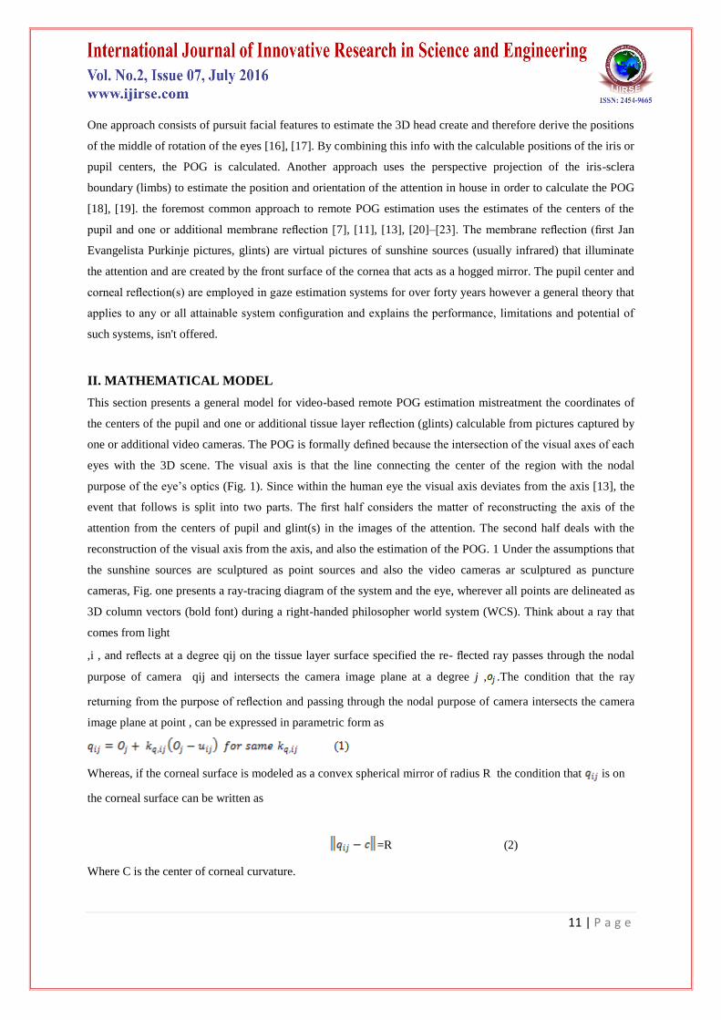
Fig. 1. Ray-tracing diagram (not to scale in order to be able to show all the elements of interest),
showing schematic representations of the eye, a camera, and a Light source.
11 | P a g e
One approach consists of pursuit facial features to estimate the 3D head create and therefore derive the positions
of the middle of rotation of the eyes [16], [17]. By combining this info with the calculable positions of the iris or
pupil centers, the POG is calculated. Another approach uses the perspective projection of the iris-sclera
boundary (limbs) to estimate the position and orientation of the attention in house in order to calculate the POG
[18], [19]. the foremost common approach to remote POG estimation uses the estimates of the centers of the
pupil and one or additional membrane reflection [7], [11], [13], [20]–[23]. The membrane reflection (first Jan
Evangelista Purkinje pictures, glints) are virtual pictures of sunshine sources (usually infrared) that illuminate
the attention and are created by the front surface of the cornea that acts as a hogged mirror. The pupil center and
corneal reflection(s) are employed in gaze estimation systems for over forty years however a general theory that
applies to any or all attainable system configuration and explains the performance, limitations and potential of
such systems, isn't offered.
II. MATHEMATICAL MODEL
This section presents a general model for video-based remote POG estimation mistreatment the coordinates of
the centers of the pupil and one or additional tissue layer reflection (glints) calculable from pictures captured by
one or additional video cameras. The POG is formally defined because the intersection of the visual axes of each
eyes with the 3D scene. The visual axis is that the line connecting the center of the region with the nodal
purpose of the eye’s optics (Fig. 1). Since within the human eye the visual axis deviates from the axis [13], the
event that follows is split into two parts. The first half considers the matter of reconstructing the axis of the
attention from the centers of pupil and glint(s) in the images of the attention. The second half deals with the
reconstruction of the visual axis from the axis, and also the estimation of the POG. 1 Under the assumptions that
the sunshine sources are sculptured as point sources and also the video cameras ar sculptured as puncture
cameras, Fig. one presents a ray-tracing diagram of the system and the eye, wherever all points are delineated as
3D column vectors (bold font) during a right-handed philosopher world system (WCS). Think about a ray that
comes from light
,i , and reflects at a degree qij on the tissue layer surface specified the re- flected ray passes through the nodal
purpose of camera qij and intersects the camera image plane at a degree j , .The condition that the ray
returning from the purpose of reflection and passing through the nodal purpose of camera intersects the camera
image plane at point , can be expressed in parametric form as
Whereas, if the corneal surface is modeled as a convex spherical mirror of radius R the condition that is on
the corneal surface can be written as
=R (2)
Where C is the center of corneal curvature.
12 | P a g e
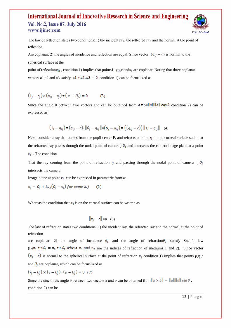
The law of reflection states two conditions: 1) the incident ray, the reflected ray and the normal at the point of
reflection
Are coplanar; 2) the angles of incidence and reflection are equal. Since vector is normal to the
spherical surface at the
point of reflection , condition 1) implies that points1; ,c and are coplanar. Noting that three coplanar
vectors a1,a2 and a3 satisfy , condition 1) can be formalized as
Since the angle θ between two vectors and can be obtained from b= condition 2) can be
expressed as
= (4)
Next, consider a ray that comes from the pupil center P, and refracts at point on the corneal surface such that
the refracted ray passes through the nodal point of camera j, and intersects the camera image plane at a point
. The condition
That the ray coming from the point of refraction and passing through the nodal point of camera j,
intersects the camera
Image plane at point can be expressed in parametric form as
Whereas the condition that is on the corneal surface can be written as
=R (6)
The law of refraction states two conditions: 1) the incident ray, the refracted ray and the normal at the point of
refraction
are coplanar; 2) the angle of incidence and the angle of refraction satisfy Snell’s law
(i.e are the indices of refraction of mediums 1 and 2). Since vector
is normal to the spherical surface at the point of refraction condition 1) implies that points p, ,c
and are coplanar, which can be formalized as
Since the sine of the angle θ between two vectors a and b can be obtained from ,
condition 2) can be

13 | P a g e
Expressed as
where is the effective index of refraction of the aqueous humor and cornea combined and is the index of
refraction
of air . In this model, the refraction at the aqueous humor cornea interface is neglected since the difference
in their indices of refraction is small relative to that of the cornea-air interface. Only the refraction at the cornea-
air interface is taken into account and the aqueous humor and cornea are considered as a homogenous medium.
Finally, considering the distance between the pupil center and the center of corneal curvature leads to
Since the optic axis of the eye passes through the pupil center (p) and the center of corneal curvature , if the
above system of equations is solved for c and p , the optic axis of the eye in space can be reconstructed as the
line defined by these two points. Notice that in order to solve the above system of equations, the eye parameters
R,K and have to be known. These eye parameters are subject-specific and are not easily measured directly.
Therefore, in general, they are obtained through a calibration procedure that is performed for each subject (an
example is provided in Section III). The typical values of these eye parameters are given in Appendix A.
Since the POG is defined as the intersection of the visual axis rather than the optic axis with the scene, the
relation between these two axes has to be modeled. The visual axis is the line
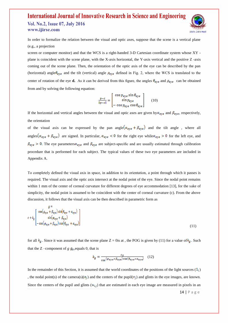
Fig. 2. Orientation of the optic axis of the eye
Defined by the nodal point of the eye and the center of the fovea (i.e., the highest acuity region of the retina
corresponding to 0.6 to 1 of visual angle), and deviates from the optic axis [13] (Fig. 1). In a typical adult human
eye, the fovea falls about 4–5
Temporally and about 1.5 below the point of intersection of the optic axis and the retina [24].
14 | P a g e
In order to formalize the relation between the visual and optic axes, suppose that the scene is a vertical plane
(e.g., a projection
screen or computer monitor) and that the WCS is a right-handed 3-D Cartesian coordinate system whose XY -
plane is coincident with the scene plane, with the X-axis horizontal, the Y-axis vertical and the positive Z -axis
coming out of the scene plane. Then, the orientation of the optic axis of the eye can be described by the pan
(horizontal) angle and the tilt (vertical) angle defined in Fig. 2, where the WCS is translated to the
center of rotation of the eye d. As it can be derived from this figure, the angles and can be obtained
from and by solving the following equation:
(10)
If the horizontal and vertical angles between the visual and optic axes are given by and , respectively,
the orientation
of the visual axis can be expressed by the pan angle and the tilt angle , where all
angles are signed. In particular, for the right eye while for the left eye, and
. The eye parameters and are subject-specific and are usually estimated through calibration
procedure that is performed for each subject. The typical values of these two eye parameters are included in
Appendix A.
To completely defined the visual axis in space, in addition to its orientation, a point through which it passes is
required. The visual axis and the optic axis intersect at the nodal point of the eye. Since the nodal point remains
within 1 mm of the center of corneal curvature for different degrees of eye accommodation [13], for the sake of
simplicity, the nodal point is assumed to be coincident with the center of corneal curvature (c). From the above
discussion, it follows that the visual axis can be then described in parametric form as
(11)
for all . Since it was assumed that the scene plane Z = 0is at , the POG is given by (11) for a value of . Such
that the Z –component of g ,equals 0, that is
(12)
In the remainder of this Section, it is assumed that the world coordinates of the positions of the light sources ( )
, the nodal point(s) of the camera(s)( ) and the centers of the pupil( ) and glints in the eye images, are known.
Since the centers of the pupil and glints ( ) that are estimated in each eye image are measured in pixels in an
15 | P a g e
image coordinate system (ICS), they have to be transformed into world coordinates (Appendix B). In order to
transform from image coordinates into world coordinates, all camera parameters, including the position of the
nodal Point( ) must be known. Typically, the camera parameters are estimated through a camera calibration
procedure [25], whereas the positions of the light sources are measured directly. In general, the system structure
is fixed and, hence, these system parameters are measured/estimated only once during system set up.
The above development shows that 1) the reconstruction of the optic axis of the eye as the line defined by the
center of corneal curvature (c) and the pupil center(p) , using (1)–(9), depends on the system configuration (i.e.,
number of cameras and light sources) and 2) once the optic axis of the eye is obtained, the reconstruction of the
visual axis and the estimation of the POG, using (10)–(12), are independent of the system configuration. For this
reason, the following subsections concentrate on the reconstruction of the optic axis of the eye for different
system configuration, which are presented in order of increasing complexity. The purpose of increasing system
complexity is to relax constraints on subject’s head movements and simplify the calibration procedure.
2.1 One Camera and One Light Source
The simplest system configuration consists of a single camera and a single light source. In this case, if the eye
parameters R,K and are known, the system of equations (1)–(9) with i=1 and j=1, is equivalent to 13 scalar
equations with 14 scalar unknowns. This means that the problem cannot be solved unless another constraint
such as
is introduced. This constraint can be satisfied if the head is fixed relative to the system or if the distance between
the eye and the camera is estimated somehow (e.g., magnetic head tracker, ultrasonic transducer, auto-focus
system, etc.).
In general, gaze estimation systems that use one corneal reflection and one light source do not solve the above
system of equations but rather use the vector from the pupil center to the corneal reflection in the eye image to
compute the gaze direction relative to the camera axis [13], and either assume that the head movements are
negligible or have means to estimate the position of the eye in space (e.g., combination of a moving camera or
moving mirrors that track the eye and an auto-focus system or an ultrasonic transducer) [7], [11], [21]–[23].
However, the above system of equations demonstrates the limitations of the single camera-single light source
configuration when the head is not completely stationary. The next subsection presents the simplest
configuration that allows for the estimation of the POG from the centers of pupil and glints, without any
constraints on head movements and without using any additional device to estimate the position of the eye in
space.
2.2. One Camera and Multiple Light Sources
The use of multiple light sources allows for the solution of the system of equations (1)–(9) with i= 1……. N-1
and j=1 if the

16 | P a g e
eye parameters ( R, K and n1)are obtained through a calibration procedure. In this case, it is advantageous to
substitute (1) into
(3) to obtain
This equation means that the center of corneal curvature c belongs to each plane defined by the nodal point of
camera j, light source i, and its corresponding image point . Moreover, for each camera j all those planes
intersect at the line defined by points c and . Since in this case there is only one camera, the subscript that
identifies the camera can be dropped for simplicity of notation and, by noting that , (14), i= 1,……,N
can be written in matrix form as
(15)
From the interpretation of (14) it follows that matrix M has, at most, rank 2. If M has rank 2, the solution to (15)
is given by an equation of the form
(16)
Which defined vector ( c-o) up to a scale factor. From this reasoning, it follows that (1), (2),
(4), and
(16) are equivalent to scalar equations with scalar unknowns. In particular,
when , is a unit
Vector in the direction of the line of intersection of the planes whose normal’s are given
by and thus
(17)
and (1), (2), (4), and (16) are equivalent to 13 scalar equations with 12 scalar unknowns.
In the special case that M in (15) has rank 1 [b=0 in (17)], which means that all normal’s given by
are Parallel. the effective number of scalar equations decreases to . In the case that
N = 2, it results in the equivalent to 12 scalar equations with 12 scalar unknowns.
Consequently, if multiple light sources are used, there are enough equations to solve for the center of corneal
curvature c . Knowing c .(5) and (6) are used to compute the point of refraction (4scalar unknowns and 4
scalar equations).

17 | P a g e
Knowing c and r ,(7)–(9) are used to compute (3 scalar unknowns and 3 scalar equations). Knowing C and p ,
the optic axis of the eye can be reconstructed as the line defined by these two points. Notice that the eye
parameters and must be known in order to reconstruct the optic axis of the eye and thus be able to
estimate the POG.
The above discussion shows that one camera and two light sources is the simplest configuration that allows for
the reconstruction of the optic axis of the eye from the centers of pupil and glints while allowing for free head
movements. The above analysis also shows that knowing c (the center of corneal curvature), the calculation of p
(the pupil center) is independent of the number of light sources (7 scalar equations and 7 scalar unknowns
regardless of the number of light sources). In the next subsection, system configuration that allow for the
reconstruction of the optic axis of the eye without the need for a subject-specific calibration procedure are
discussed.
2.3. Multiple Cameras and Multiple Light Sources
When multiple cameras and multiple light sources are used, it is possible to discard all equations that contain the
eye parameters while still being able to reconstruct the optic axis of the eye by using the remaining
equations. In order to keep the notation simple, the discussion that follows is carried out for two cameras, noting
that the extension to more cameras is trivial. When two cameras and multiple light sources are used.
(14), can be written in matrix form as
= (18)
After applying the distributive property for the dot product, rearranging terms and noting that .If M2
has rank 3,c
Can be obtained from (18) by using the left pseudo inverse of M2 as
(19)
If only 3 linearly independent rows of and the corresponding rows of h are considered in (18), then (19)
reduces to
.
Note that when (5) and (7) are combined, they correspond to the physical condition that for each camera (refer
also to Fig. 1),
the pupil center the point of refraction , the nodal point of the camera the image of the pupil center
, and the Center of corneal curvature are coplanar. For this system configuration with two cameras, it is
convenient to represent this

18 | P a g e
Physical condition as
(20)
Since the optic axis of the eye is defined by points p and c these equations mean that the optic axis of the eye
belongs to the plane defined by points (normal given by ) and to the plane
defined by points (normal given by ). Therefore, the optic axis of the eye is
the line of the intersection of those two planes and its direction is given by
If the solution to (20) can be expressed as
which defined vector ( p-c) up to a scale factor (notice that the distance between the pupil center and
the center of corneal curvature). In this way, knowing c and the direction( p-c) of vector i.e., the direction of
vector S , the optic axis of the eye can be reconstructed without actually knowing the eye parameters
III. EXPERIMENT RESULT
This section presents a specific system implementation that is used to estimate the POG on a computer screen.
The system utilizes two near-infrared (850 nm) light sources that are symmetrically positioned at the sides of a
19-in computer monitor and a video camera (640 480 pixels, 1/3-in charge-coupled device with a 35-mm lens)
that is centered under the screen. A typical image from the video camera for a subject sitting at a distance of 65
cm from the monitor (typical viewing distance), with his head approximately at the center of the region of
allowed head movement, is shown in Fig. 3. This specific system can tolerate only moderate head movements of
about 3 cm laterally, 2 cm vertically, and 4 cm backward/forward, before the eye features are no longer in the
field of view of the camera or are out of focus.
To estimate the POG on the screen, a set of system and subject-specific eye parameters has to be
measured/estimated. Since the system components are fixed relative to the computer monitor, the system
parameters (the position of the two light sources, and , and the extrinsic and intrinsic camera parameters,
which include the nodal point of the camera, )are measured/estimated only once during system set up. The
subject-specific eye parameters ( ) are obtained through a calibration procedure that is
performed once for each subject. In the calibration procedure, the subject exits on 9 evenly distributed points
that are presented sequentially on the screen. For each fixation point, 100 estimates of the image

19 | P a g e
Fig. 3. Sample eye image showing the pupil and the two corneal reflection(glints).
Coordinates of the centers of pupil and glints are obtained and the average coordinates of these features are
computed. Using the average coordinates of the centers of pupil and glints, the eye parameters are optimized to
minimize the sum of the square errors between the points on the screen and the estimated points-of-gaze [27].
The initial guess for the optimization corresponds to the typical values of the eye parameters given in Appendix
A. During the calibration procedure the head is positioned at the center of the region of allowed head
movements (central position).
To estimate the POG, the coordinates of the centers of pupil and glints are first estimated in each image captured
by the video camera [28]. These image coordinates are then transformed into world coordinates (Appendix B)
as for the pupil center, and and for the glints. Next, the center of corneal curvature
c, is calculated from (1), (2), (4) and (16), (17). Knowing c and r, (5) and (6) are used to
compute the point of refraction Knowing and , (7)–(9) are used to compute p. Knowing c and p the optic
axis of the eye in space is reconstructed as the line defined by these two points. Finally, using (10)–(12), the
visual axis of the eye is obtained and the POG on the screen is estimated.
A preliminary evaluation of the performance of this POG estimation system was carried out through
experiments with 4 subjects. In these experiments, the head of each subject was placed in the central position
and 4 positions at the edges of the region of allowed head movements. The 4 edge positions correspond to
lateral and backward/forward head displacements. For each head position, the subject was asked to fixation on 9
points on the computer screen and 100 estimates ( 3.3 s at 30 estimates/s) of the POG were obtained for each
fixation point. The resulting root-mean-square (RMS) errors in the estimation of the POG for the central position
and the edge positions are summarized in Table I (RMS error). Table I also shows the RMS errors when the
POG was estimated for the average of the coordinates of the centers of pupil and glints (ACPG-RMS error). A
typical example of POG estimation errors for the central head position is shown in Fig. 4. The ACPG-RMS

20 | P a g e
errors (Table I) correspond to the deviation of the white crosses from the centers of the dotted circles in Fig. 4
and are the result of bias in the estimation of the POG. The dispersion of the asterisks around the white crosses
is caused by noise in the estimates of the image coordinates of the centers of pupil and glints. The RMS errors
shown in the last column of Table I correspond to the combined effects of bias and dispersion of the POG
estimates. It can be also observed that the RMS errors for the edge head positions are larger than the RMS errors
for the central head position.
TABLE I
EXPERIMENTALRMS POINT-OF-GAZEESTIMATION ERRORS
Fig. 4. Experimental POG estimation results for subject J. K. The centers of the dotted circles (10 mm
radius) indicate the intended fixation points, the asterisks represent the estimates of the POG, and the
white crosses represent the estimates of the POG for the average coordinates of the centers of pupil and
glints.
In order to understand the observed errors, the effects of differences between the shape of real human corneas
and the ideal spherical corneal shape assumed in the model of Section II (corneal asphericity), as well as the
effects of noise in the estimation of the centers of pupil and glints in the eye images, were studied through

21 | P a g e
numerical simulations. The effects of corneal asphericity were studied using an ellipsoidal corneal model[29]. In
this model, the corneal surface is modeled as a section of an ellipsoid that has one of its axes coincident with the
optic axis of the eye and whose cross-sections perpendicular to the optic axis are circular. This ellipsoidal
corneal model can be completely characterized by the distance between the apex of the cornea and the center of
rotation of the eye (13.1 mm—see Appendix A), the radius of curvature at the apex of the cornea (7.8 mm—see
Appendix A) and the radius of curvature of the cornea at the boundary with the sclera (at 6 mm from the optic
axis, ). Using this ellipsoidal corneal model, the image coordinates of the centers of pupil and glints were
computed for the same fixation points and the same head positions that
TABLE II
SIMULATION RMS POINT-OF-GAZEESTIMATION ERRORS
Were used in the experiments. As in the experiments, the central head position was used to calibrate the eye
parameters. The Resulting RMS POG estimation errors for different degrees of corneal asphericity (different
values of the radius of curvature at the cornea-sclera boundary , ) are summarized in Table II (NFD-RMS
error). These POG estimation errors are only due to the difference between the ellipsoidal corneal model used to
calculate the image coordinates of the centers of pupil and glints and the spherical corneal model (Section II)
used to estimate the POG. It is clear from Table II that the POG estimation errors increase with the degree of
corneal asphericity. In particular, corneal asphericity results in sensitivity to head displacements, making the
RMS error for the edge head positions larger than the RMS error for the central head position. Furthermore, the
sensitivity to head displacements also increases with the degree of corneal asphericity. If the cornea were truly
spherical, head displacements would have no effect on the POG estimation error.
In order to simulate the effect of noise in the estimates of the centers of pupil and glints in the video images,
each coordinate of the centers of pupil and glints obtained with the ellipsoidal corneal model was contaminated
with 100 independent realize- tions of an additive zero-mean Gaussian process with a standard deviation of 0.1
pixel. The properties of the noise were similar to those observed in the system using a stationary artificial eye.

22 | P a g e
As for the noise-free simulations described above, the POG was estimated for the central head position and for
the 4 edge head positions. The RM Serrors of the POG estimates for different degrees of corneal asphericity are
summarized in the last column of Table II (RMS error). Fig. 5 shows simulation results for the central head
position and for corneal asphericity that produces an error pattern that is similar to that of the example in Fig.
4. The bias of the white crosses from the centers of the dotted circles is only due to corneal asphericity. The
dispersion of the asterisks around the white crosses is caused by the simulated noise in the estimation of the
image coordinates of the centers of pupil and glints. The combined effects of estimation bias and dispersion
result in the RMS errors shown in the last column of Table II. It can be observed that the errors obtained
through simulations (Fig. 5) are consistent with the experimental errors (Fig. 4). This example clearly
demonstrates
Fig. 5. Simulation results for the ellipsoidal corneal model with R =11mm The centers of the
dotted circles(10 mm radius) indicate the actual fixation points. The white crosses represent the
estimates of the POG for the noise-free data. The asterisks represent the estimates of the POG
when zero-mean Gaussian noise with a standard deviation of 0.1 pixel was added to the
coordinates of the centers of pupil and glints.
.IV. CONCLUSION
This paper presented remote POG estimation systems that use the coordinates of the centers of the pupil and
corneal reflection (glints) estimated from video images. It was shown that as system complexity (i.e., the
number of light sources and the number of cameras) increases, the number of subject-specific parameters that
have to be estimated through calibration can be reduced and the constraints on head movements can be relaxed.
For a system configuration that consists of one camera and one light source, the POG cannot be determined from
the coordinates of the centers of the pupil and the glint, unless the head is stationary or the head position is
estimated by some other means.
23 | P a g e
The simplest configuration that allows for the estimation of the POG, while allowing for free head movements,
consists of one camera and two light sources. To estimate the POG with this system configuration, five eye
parameters ( ) have to be estimated through a subject-specific calibration procedure that
requires the subject to fixation on multiple points. A specific system implementation that uses one camera and
two light sources to estimate the POG on a computer screen was described in detail. It was shown that the main
sources of errors in the estimation of the POG are associated with 1) corneal asphericity (deviation of the shape
of real corneas from the ideal spherical cornea assumed in the model); and 2) noise in the estimation of the
centers of pupil and glints in the eye images. Experimental results obtained with four subjects showed that by
Using the general theory, the POG on the computer screen can be estimated with an RMS error of less than 0.9
of visual angle. If at least two cameras and at least two light sources are used, it is possible to reconstruct the
optic axis of the eye without a subject-specific calibration procedure (i.e., calibration-free system). In order to
reconstruct the visual axis of the eye and thus be able to estimate the POG, the angular deviation between the
optic axis and the visual axis ( ) still needs to be known. The angular deviation between the optic
and visual axes can be estimated through a simple calibration procedure in which the subject is required to fixate
on a single point. A single point calibration can be performed even with infants by presenting a flashing object
to attract their attention.
A system with two cameras and multiple light sources is under development. Preliminary simulations for a
system with two cameras and two light sources (under similar conditions to those described in Section III)
yielded RMS POG estimation errors that were less than 7.75 mm (about 0.68 of visual angle). These preliminary
results suggest that it is feasible to implement a POG estimation system that requires only a single-point
calibration and has an accuracy of 1 of visual angle.
REFERENCES
[1] N. Moray, ―Designing for attention,‖ in Attention: Selection, Aware-ness, and Control, A. Baddeley and L.
Weiskrantz, Eds.. New York:Clarendon, 1993, pp. 111–134.
[2] M. Eizenman, L. H. Yu, L. Grupp, E. Eizenman, M. Ellenbogen, M.Gemar, and R. D. Levitan, ―A
naturalistic visual scanning approach to assess selective attention in major depressive disorder,‖ Psychiat.
Res.,vol. 118, no. 2, pp. 117–128, May 2003.
[3] C. Karate kin and R. F. Asarnow, ―Exploratory eye movements to pictures in childhood-onset schizophrenia
and attention-deficit/hyperactivity disorder (ADHD),‖ J. Abnorm. Child Psychol., vol. 27, no. 1, pp.35–49,
Feb. 1999.
[4] M. De Luca, E. Di Pace, A. Judica, D. Spinelli, and P. Zoccolotti, ―Eye movement patterns in linguistic and
nonlinguistic tasks in developmental Surface dyslexia,‖ Neuropsychologia, vol. 37, no. 12, pp. 1407–1420,
Nov. 1999.
[5] M. Eizenman, T. Jares, and A. Smiley, ―A new methodology for the analysis of eye movements and visual
scanning in drivers,‖ presented at the 31st Annu. Conf. Erg. & Safety, Hall, QC, Canada, 1999.
24 | P a g e
[6] J. L. Harbluk, I. Y. Noy, and M. Eizenman, ―The impact of cognitive distraction on driver visual and vehicle
control,‖ presented at the Transportation Research Board 81st Annual Meeting, Washington, DC, Jan. 2002.
[7] D. Cleveland, ―Unobtrusive eyelid closure and visual point of regard measurement system,‖ in Proc. Tech.
Conf. Ocular Measures of Driver Alertness, sponsored by The Federal Highway Administration—Office of
Motor Carrier and Highway Safety and The National Highway Traffic Safety Administration Office of
Vehicle Safety Research, Herndon, VA, 1999, pp. 57–74.
[8] P. A. Wetzel, G. Krueger-Anderson, C. Poprik, and P. Bascom, ―An Eye Tracking System for Analysis of
Pilots’ Scan Paths,‖ United States Air Force Armstrong Laboratory, Tech. Rep. AL/HR-TR-1996-0145, Apr.
1997.
[9] J. H. Goldberg and X. P. Kotval, ―Computer interface evaluation using eye movements: methods and
constructs,‖ Int. J. Ind. Erg., vol. 24, no. 6, pp. 631 645, Oct. 1999.
[10] R. Sharma, V. I. Pavlovic and T. S. Huang, ―Toward multimodal human-computer interface,‖ Proc. IEEE,
vol. 86, no. 5, pp. 853–869, May 1998.
[11] T. E. Hutchinson, K. P. White, W. N. Martin, K. C. Reichert, and L. A. Frey, ―Human-computer interaction
using eye-gaze input,‖ IEEE Trans. Syst., Man, Cybern., vol. 19, no. 6, pp. 1527–1534, Nov./Dec.1989.
[12] L. A. Frey, K. P. White, and T. E. Hutchinson, ―Eye-gaze word processing,‖IEEE Trans. Syst., Man,
Cybern., vol. 20, no. 4, pp. 944–950, Jul./Aug. 1990.
[13] L. R. Young and D. Sheena, ―Methods and designs—survey of eye movement recording methods,‖ Behav.
Res. Meth. Instrum., vol. 7, no. 5, pp. 397–429, 1975.
[14] R. S. Allison, M. Eizenman, and B. S. K. Cheung, ―Combined head and eye tracking system for dynamic
testing of the vestibular system,‖ IEEE Trans. Biomed. Eng., vol. 43, no. 11, pp. 1073–1082, Nov. 1996.
[15] L. H. Yu and M. Eizenman, ―A new methodology for determining point-of-gaze in head-mounted eye
tracking systems,‖ IEEE Trans. Biomed. Eng., vol. 51, no. 10, pp. 1765–1773, Oct. 2004.
[16] R. Newman, Y. Matsumoto, S. Rougeaux, and A. Zelinsky, ―Real-time stereo tracking for head pose and
gaze estimation,‖ in Proc. 4th IEEE Int. Conf. Automatic Face & Gesture Recognition, 2000, pp. 122–128.
[17] Y. Matsumoto and A. Zelinsky, ―An algorithm for real-time stereo vision implementation of head pose and
gaze direction measurement, ―in Proc. 4th IEEE Int. Conf. Automatic Face & Gesture Recognition,2000, pp.
499–504.
[18] J. G. Wang and E. Sung, ―Gaze determination via images of irises,‖ Image Vis. Comput., vol. 19, no. 12,
pp. 891–911, Oct. 2001.
[19] , ―Study on eye gaze estimation,‖ IEEE Trans. Syst., Man, Cybern. B, vol. 32, no. 3, pp. 332–350, Jun.
2002.
[20] A. Cowey, ―The basis of a method of perimetry with monkeys,‖ Q. J.Exp. Psychol., vol. 15, pt. 2, pp. 81–
90, 1963.
[21] J. Merchant, R. Morrissette, and J. L. Porterfield, ―Remote measurementof eye direction allowing subject
motion over one cubic foot of space,‖ IEEE Trans. Biomed. Eng., vol. BME-21, no. 4, pp. 309–317,Jul.
1974.

25 | P a g e
[22] A. Sugioka, Y. Ebisawa, and M. Ohtani, ―Noncontact video-based eye gaze detection method allowing
large head displacements,‖ in Proc. 18th Annu. Int. Conf. IEEE Eng. Med. Biol. Soc., 1996, vol. 2, pp. 526–
528.
[23] Y. Ebisawa, M. Ohtani, A. Sugioka, and S. Esaki, ―Single mirror tracking system for free-head video-based
eye-gaze detection method,‖ in Proc. 19th Annu. Int. Conf. IEEE Eng. Med. Biol. Soc., 1997, vol. 4, pp.
1448–1451.