remote pilot-controlled docking with television
TRANSCRIPT

NASA
d d 0 @? n a c 4 c/) 4 z
TECHNICAL
* z
NOTE
REMOTE PILOT-CONTROLLED DOCKING WITH TELEVISION
by Edward R. Long? Jr.? Jack E. PenningtoH? and Perry L. Deul
Langley Research Center Langley Station, Hampton, Va.
N A T I O N A L AERONAUTICS A N D SPACE A D M I N I S T R A T I O N WASHINGTON, D

NASA TN D-3044
REMOTE PILOT- CONTROLLED DOCKING WITH TELEVISION
By Edward R. Long, Jr., Jack E. Pennington, and Pe r ry L. Deal
Langley Research Center Langley Station, Hampton, Va.
NATIONAL AERONAUTICS AND SPACE ADMINISTRATION
For sale by the Clearinghouse for Federal Scientific and Technical lnformotion Springfield, Virginia 22151 - Price $2.00

REMOTE PILOT-CONTROLLED DOCKING WITH TELEVISION
By Edward R. Long, Jr., Jack E. Pennington, and Perry L. Deal
Langley Research Center
SUMMARY
An invest igat ion of t h e use of closed-circuit t e lev is ion (CCTV) as idn instrument f o r pi lot-control led visual docking of two space vehicles w a s con- ducted on t h e Langley rendezvous docking simulator ( R D S ) . The RDS i s a ful l - scale dynamic f a c i l i t y which i s used t o study pi lot-control led docking of var- ious types of space vehicles. The vehicles simulated i n t h i s study w e r e t h e Gemini spacecraft and t h e Agena booster.
The f irst pa r t of t h i s two-part study w a s designed t o compare t h e p i l o t ' s a b i l i t y t o remotely control a docking by using only information obtained from a te lev is ion monitor with h i s a b i l i t y t o control t he docking by d i r ec t vis ion from within the spacecraft . For the remote f l i g h t s a closed-circuit t e lev is ion cam- era was mounted i n t h e Gemini cockpit with t h e camera lens f ixed a t t h e p i l o t ' s cockpit eye posi t ion. Comparison of t he results of the f i rs t pa r t of t he study with e a r l i e r Gemini docking studies shows t h a t t he e r r o r band (of terminal accuracies) of docking with t h e CCTV i s very similar t o t h a t i n ac tua l visual docking.
I n the second p a r t of t h e study t h e camera was mounted i n the Gemini nose with the lens center l i n e along the longi tudinal ax i s of t he vehicle, so t h a t t he camera saw no pa r t of the Gemini vehicle. A n i n t e g r a l pa r t of t h i s camera location was a v isua l a i d mounted on the t a r g e t ( t h e Agena booster) . generalized vehicle-control systems w e r e used i n order t o obtain more general r e s u l t s and t o show t h e e f f e c t s of t he control system on the p i l o t ' s control of the ac t ive vehicle. Results of t he second p a r t of t he study show t h a t , with the assis tance of the v i sua l a i d on t h e t a rge t , t h e p i l o t could commit t o a docking with s m a l l e r ror .
Three
INTRODUCTION
I n fu ture manned space-vehicle operations, some instances w i l l arise i n which t h e astronaut must control vehicles he cannot see d i rec t ly . I n a situa- t i o n such as t h i s , t h e p i l o t would e i t h e r be remote t o t h e operation o r merely unable t o see d i r ec t ly t h e work he i s doing. Such conditions may arise from considerations of vehicle design and crew safety. Hence a means must be pro- vided t o give the p i l o t a v i sua l display of the problem or proper and su f f i c i en t instrumentation t o replace t h e loss of d i r ec t v i sua l observation.

One t a sk f o r which d i r ec t vision i s advantageous i s the docking maneuver. The present Gemini vehicle designs provide the p i l o t with a d i rec t view of the docking operation. Much work has been done i n the study of Gemini docking problems with a d i r ec t view as indicated i n references 1 and 2. However, l i t t l e consideration has been given t o providing the p i l o t with a visual scene of the problem when he i s e i the r unable t o see d i r ec t ly or i s remote t o the act ive vehicle. If the Gemini or some other c r a f t were used a s a space tug fo r t rans- porting supplies, possibly radioactive or dangerous, perhaps the p i l o t would have t o be remotely located f o r h i s own safety and would not be able t o see where he was depositing h i s supplies. If t h i s were the case, then one means of giving the p i l o t a su i tab le view would be t o mount a te levis ion camera on the load or on the spacecraft so t h a t the docking interface could be seen.
The purpose of the present study i s t o invest igate a means of supplying the p i l o t with adequate v isua l information fo r docking when he i s remotely located. The means chosen i s t o locate a te lev is ion camera on the simulated Gemini model and transmit the camera's view t o the remote p i l o t .
A te levis ion monitor provided the p i l o t with a view of the operation a s the camera saw it. Two locations were chosen f o r the camera. The f i r s t loca- t i on was i n the Gemini cockpit with the lens a t the posit ion where the p i l o t ' s eye would be. I n t h i s location the camera saw what the p i l o t would have seen had he occupiedthe cockpit. The r e su l t s of this pa r t of the study a re compared with studies made e a r l i e r i n which the same p i l o t s flew from inside the Gemini cockpit. The second camera location was i n the nose of the Gemini spacecraft. This second par t of t he study i s a continuation of the investigation of the use of CCTV. However, no comparison of r e s u l t s i s made with any other study or with the f i r s t par t of t h i s study. information f o r t h i s camera location, a visual a i d was developed and i s dis- cussed herein.
Since the t a rge t lacked suf f ic ien t visual
SYMBOLS
The un i t s used f o r the physical quant i t ies defined i n t h i s paper a re given both i n U.S. Customary Units and i n the Internat ional System of Units ( S I ) ( r e f . 3 ) . paper.
Appendix A presents fac tors r e l a t ing the systems as used i n t h i s
Figure 1 presents the t rans la t ion coordinates used herein.
x t center-of-mass posit ion i n x direct ion of vehicle with respect t o ta rge t , f t (a)
center-of-mass posit ion i n y direct ion of vehicle with respect t o ta rge t , f t ( m ) y t
center-of-mass posit ion i n z direct ion of vehicle with respect t o Z t t a rge t , f t ( m )
2
1 1 1 111111111 I 1 I I I I I I I I~ I I l l I I '

la teral nose e r ror of vehicle with respect t o t a rge t , f t (m) Y n
Zn v e r t i c a l nose e r ro r of vehicle with respect t o t a rge t , f t ( m )
e p i t ch e r ro r of vehicle with respect t o t a rge t , deg
rp r o l l e r ro r of vehicle with respect t o t a rge t , deg
4f yaw e r ro r of vehicle with respect t o t a rge t , deg
W f weight of t o t a l fuel used, l b (kg)
t f l i g h t t i m e , s
X,Y,Z i n e r t i a l coordinates
A dot over a quantity represents t he f irst der ivat ive with respect t o t i m e .
APPARATUS
Simulator
The Langley rendezvous docking simulator (RDS) , a fu l l - sca l e dynamic s ix- degree-of-freedom f a c i l i t y used t o study docking of various types of space vehi- c l e s , i s shown i n f igure 2. (See r e f . 4 . ) A fu l l - s i ze model of t he Gemini spacecraft , which i s the ac t ive vehicle i n t h i s study, i s mounted i n a hydrau- l i c a l l y driven three-axis gimbal system which provides p i tch , roll, and yaw a t t i t udes . This gimbal system i s then suspended i n a horseshoe-shaped frame which i s suspended by eight cables from an e l e c t r i c a l l y driven overhead carriage-dolly arrangement which provides the three degrees of t r ans l a t iona l freedom. The a t t i t u d e and t rans la t ion systems respond t o the p i l o t ' s control inputs through a programed analog computer. The p i l o t ' s control inputs cause voltage s ignals representing th rus t t o be transmitted t o t h e computer where they a re transformed i n the computer from the body ax i s system t o an i n e r t i a l coor- dinate system.
Target
Figure 3 shows the model of the Agena booster used i n t h i s study. The model was a wooden cy l indr ica l frame 25 f e e t (7.62 m) long covered with t r ans - lucent paper. The docking adapter cone w a s of balsa wood and bakel i te .
Television Equipment
The 800-line horizontal resolution, 673-scanning-line te lev is ion un i t used f o r t h i s study consisted of two monitors, a control package, and a camera. One of t h e monitors and t h e control package a re shown i n f igure 4. The camera can
3

be seen i n figures 5 and 6. of the system i s given i n t a b l e I.
A more de ta i led description of t he specif icat ions
P r io r t o each set of runs, t he control box and camera were adjusted t o obtain a p ic ture which w a s s a t i s f ac to ry t o the p i l o t i n qual i ty , d e t a i l , and contrast . w a s switched t o an automatic mode. s a to r maintained the same image conditions on the monitor regardless of t he change within a design l i m i t of t he l i g h t incident on the t a rge t . large change i n l i g h t in tens i ty , t h e compensator s t ab i l i zed t h e image qua l i ty under t h e new conditions. That is, the image did not wash out because of large changes i n the l ight in t ens i ty incident on the t a rge t .
A f t e r t he image conditions were manually selected, t he control box I n t h i s mode, the automatic light compen-
For any
P i l o t Compartment
The p i l o t w a s located i n an in f l a t ab le planetarium ( f i g . 7) adjacent t o the RDS, which i s used primarily t o simulate t h e darkness and void of space. The p i l o t sat before the te lev is ion monitor i n a chair , as shown i n f igure 4. Figure 8 shows t h e a t t i t u d e cont ro l le r which w a s used with h i s r i gh t hand, and figure 9 shows the t r ans l a t ion cont ro l le r which w a s operated by h i s l e f t hand. By actuat ing these cont ro l le rs with only the v isua l information supplied by the monitor, t he p i l o t controlled the alinement and closure of t h e vehicles t o docking.
TEST PROGRAM
Camera i n Cockpit
The f i rs t pa r t of t h e study was conducted with t h e camera i n the l e f t s ide of the cockpit of t he Gemini model ( f i g . 5 ) . The camera was posit ioned so t h a t i t s lens occupied the same cockpit locat ion a s the p i l o t ' s eyes.
The purpose of t h i s p a r t of the study w a s t o determine the f e a s i b i l i t y of using CCTV by comparing remote runs made with t h e camera i n the cockpit with runs using d i r ec t vis ion made by the same p i l o t s i n an e a r l i e r study. The data of these e a r l i e r runs when the p i l o t s w e r e i n t h e cockpit were taken from ref- erences 1 and 2.
Camera i n Nose
The second p a r t of t he study was conducted with the camera i n the nose of t he Gemini spacecraft ( f i g . 6 ) . and the camera positioned so t h a t i t s lens looked along the longi tudinal center l i n e of t he spacecraft , t h a t i s , there w a s no para l lax due t o the camera location.
The nose p l a t e of t he spacecraft was removed
4

T h i s pa r t of the study w a s conducted t o invest igate the e f f ec t of the p i l o t not being able t o see the body of his own vehicle. of the Gemini nose there was no pa r t of the spacecraft i n the picture a s i n the case where the camera was i n t h e cockpit; thus, the spacecraft served a s a camera mount only and not as any defined vehicle. uration was a generalization, the thrus t ing leve ls of the rockets were a rb i - t r a r i l y se t a t nominal leve ls of 0.4 fps2 (0.122 m/s2) i n t rans la t ion and 0.4 deg/s2 i n a t t i tude ; a generalized 50-percent a t t i tude- t rans la t ion cross coupling was used. command required half the available a t t i tude-control power t o overcome the acceleration. The same ef fec t on t rans la t ion occurred when a t t i t u d e control was commanded.
With the camera i n the end
To insure t h a t t h i s config-
Thus the coupling i n a t t i t u d e resu l t ing from a t rans la t ion
Cross coupling occurs because the j e t s do not f i r e through the center of the vehicle mass. Hence a f i r i n g t o cause t rans la t ion up, down, l e f t , or r i gh t created an a t t i t u d e r a t e i n p i tch down, p i tch up, yaw r ight , o r yaw l e f t , respectively. a l so created a p i tch r a t e which required 1 second of a t t i t u d e f i r i n g i n pi tch t o stop the a t t i t ude r a t e .
I n t h i s case, a 2-second f i r i n g of a j e t t o cause v e r t i c a l r a t e
Target Visual Aids
The i n i t i a l runs made with the camera i n the nose of the Gemini spacecraft were attempted without any v isua l assistance other than t h a t provided by the ta rge t . information of posi t ion r e l a t ive t o the act ive vehicle t o the t a rge t . This d i f - f i c u l t y was in tens i f ied close t o the ta rge t where the camera saw only the inside of the docking adapter which was white. mately 15 f e e t (4.57 m) i n f ront of the ta rge t with poor cues of posi t ion and hold t h i s alinement by in tu i t i on t o docking. v i sua l a i d was necessary t o provide the camera with a view containing suf f ic ien t v i sua l information throughout the approach so the p i l o t could dock with a small e r ror . the a i d was designed t o be e f fec t ive a s f a r a s 150 f ee t (45.72 m ) from the t a rge t .
The t a sk of docking was very d i f f i c u l t because of insuf f ic ien t v i sua l
Hence the p i l o t s had t o a l ine approxi-
It was decided t h a t some type of
Although runs were i n i t i a t e d only 50 f ee t (15.24 m) from t h e t a rge t ,
It was decided t h a t a double-angle truncated cone would solve the problems. A cross-sectional drawing of t h i s cone i s shown i n f igure 10. A cone was used fo r two reasons. center of which it had t o a l ine with, a cone whose maximum diameter was mounted f lush with the end of the cylinder a s shown i n f igure l l ( a ) was i n keeping with the geometrical shape. The sameness of shape was not an overly important fea- t u r e but does allow f o r easy culmination of a l l cues whether from the a i d or the ta rge t . (2 ) With the cone a sense of depth was retr ieved, more so than would have been with a cross on each end of a rod. Two angles were used because it was desired t o employ the cone a s a v i sua l a i d f o r the e n t i r e run. angle par t of the cone was found very sui table f o r gross alinement a t large
(1) Since the camera was viewing the end of cylinder, the
The large-
5

distances while the small-angle part was used for fine alinement just prior to docking. near optimum had it been 20° to 30'. approaching camera as shown in figure ll(b) . monitor and the information used in the following manner:
It was later decided that this smaller apex angle would have been The inner part of this cone faced the
This view was transmitted to the
If an attitude rate existed, then the aid seemed to translate across the monitor screen. the concentric circles became increasingly nonconcentric while the aid trans- lated a small amount compared with translation due to attitude on the monitor screen. seemed to "bunch" at the top of the aid while spreading at the bottom. Using these two types of visual information, the pilot could distinguish attitude and translational errors and control them to docking.
On the other hand, if a pure translational-rate error existed,
For example, if the camera were high relative to the aid, the circles
Control Modes
In both parts of the study translation control was the direct (accelera- tion) mode.
With the camera in the cockpit, acceleration-command attitude control was also used. Thus, all six degrees of freedom were controlled by the accelera- tion mode with no damping. Gemini thrust levels and coupling, as defined in reference 1, were used.
In the second part of the study with the camera in the nose, three attitude control modes were studied. The mode of translation control was always acceleration command. The first attitude mode was an acceleration-command mode with 4 deg/s2 rotational on-off acceleration in each axis. control mode tested was the on-off acceleration command mode with a rate wash- out circuit. With the rate washout feature, attitude rates established were damped out upon release of the controller, through a computer feedback loop having a 2-second time constant. The third mode studied, an on-off velocity command, was somewhat different. The signal from the controller was seen by the computer as a velocity of 0.4 deg/s. position to which the computer would drive the spacecraft. attitude motion only as long as the attitude controller was displaced.
The second attitude-
This velocity was integrated to a Thus there was
FESULTS AND DISCUSSION
Since the objectives and the simulation techniques used in the two parts of this study were different, the results and conclusions for each part are examined separately.
6
I

Camera i n Cockpit
The r e s u l t s obtained with t h e CCTV camera i n the cockpit can be compared with t h e r e s u l t s of t he study reported i n reference 2. The present remote docking study using t h e closed-circui t - te levis ion system w a s conducted imme- diately after the study i n reference 2 with t h e same p i l o t s and t h e s a m e s i m - u l a to r . Two p i l o t s designated A and B w e r e used f o r t h i s pa r t of t he study.
A run w a s considered t o be f inished when the longi tudinal separation of t h e nose of the spacecraft and cone of t a rge t w a s zero. A t t h i s end.point, t he con- d i t ions w e r e in te rpre ted as t h e l a t e r a l and v e r t i c a l nose e r ro r with respect t o t h e cone.
Figure 12(a) i s a p l o t of t h e end conditions f o r p i l o t A. The squares represent t he la teral and v e r t i c a l capsule nose e r ro r a t docking f o r t he case of t h e camera i n t h e cockpit ( p i l o t remote using CCTV) . represent t h e e r ro r s a t docking when t h e p i l o t was i n the cockpit ( p i l o t using d i r ec t v i s ion) .
The s m a l l c i r c l e s
Figure 12(b) i s a p lo t of t he same type of data f o r p i l o t B.
I n both pa r t s of figure 12 the large c i r c l e s represent t he e r ro r bands within which the d i f f e ren t s e t of runs f e l l . Comparison of t he r e s u l t s f o r both p i l o t s shows t h a t t h e e r r o r band iden t i f i ed by the c i r c l e s i s smaller f o r the case when the p i l o t control led from the cockpit; however, f o r a l l runs t h e end conditions were wel l within the 1-foot (0.3048-m) e r ro r band prescribed f o r Gemini-Agena docking. The main reasons f o r t h e l a rge r spread of data f o r t he camera-in-the-cockpit runs was the l o s s of depth and aspect when viewing the Tv monitor. When viewing t h e TV monitor, t h e p i l o t only s a w a two-dimensional image. Also, i f he moved h i s head he could not see a change i n aspect of t h e t a r g e t t h a t he would see when i n t h e cockpit. This l a t t e r cue i s considered t o be helpful i n v i sua l docking. mainly i n detection of v e r t i c a l e r ro r whereas p i l o t B was affected i n both l a t e r a l and v e r t i c a l e r ror .
The lo s s of depth and aspect a f fec ted p i l o t A
I n f igure 12, t he center of t he la rge c i r c l e s i d e n t i f i e s the b i a s i n nose e r ro r r e l a t ive t o a per fec t docking. It i s in t e re s t ing t o note t h a t f o r both the camera-in-the-cockpit and pilot-in-the-cockpit cases there w a s a l e f t l a t - e r a l b i a s i n nose posi t ion. The reason f o r these charac te r i s t ics can be explained by inspection of figure 13. Figure 13 i s a two-dimensional drawing depicting the posi t ion of the vehicles j u s t p r i o r t o docking and explains the l e f t b i a s i n the end conditions. (35.6 cm) t o the l e f t of t h e longi tudinal center l i n e and hence had a v i sua l paral lax when looking a t t h e nose of t he spacecraft and guiding t o a docking. The p i l o t s took two measures t o a l l e v i a t e t h e work load caused by t h i s paral lax. One w a s t o a l i n e the eye (or camera lens) i n a gunsight fashion with t h e docking bar on the spacecraft nose and docking s l o t on t h e t a rge t . While holding t h i s alinement, t h e p i l o t f l e w high and t o the l e f t r e l a t i v e t o t h e t a rge t t o use t h e aspect of t he s ide of t he t a rge t f o r v e r t i c a l and l a t e r a l t r ans l a t ion cues. The p i l o t s remained l e f t and high during the approach u n t i l j u s t before docking and then attempted t o t r a n s l a t e r igh t and down t o eliminate t h e e r ro r . Because of cross coupling, a command t o t r a n s l a t e right caused the capsule t o yaw l e f t . Hence the nose w a s s l i g h t l y t o t h e l e f t a t docking.
The p i l o t s s a t approximately 14 inches
7

The reason fo r t h i s difference of r e su l t s f o r the p i l o t i n the cockpit and the camera i n the cockpit can be seen by a fur ther investigation of the tech- nique of approaching high and t o the l e f t . When the camera was i n the cockpit, the p i l o t s a w only a two-dimensional image, t h a t is , the dimension of depth was l o s t . the TV monitor and d id not get a change of aspect of the t a rge t . A s can be seen from f igure 12, t h i s loss of depth and aspect affected p i l o t A only i n detection of v e r t i c a l r a t e s and posit ion, causing h i s v e r t i c a l e r ror t o be greater and i n a more random dis t r ibu t ion . e r a l and v e r t i c a l sensing.
Loss of aspect was real ized when the p i l o t moved h i s head r e l a t ive t o
P i l o t B was affected i n both l a t -
During the p i l o t debriefing it was s t a t ed t h a t more caution was exercised during a TV approach compared with f l i g h t s made from within the cockpit, yet there was no f ea r of making an unsuccessful docking. T o c l a r i f y t h i s feel ing of the p i l o t s , p lo t s were made of t o t a l f u e l used against f l i g h t time f o r each run. vision ( p i l o t i n cockpit) f l i g h t s a r e superimposed.
(See f i g . 14.) The r e su l t s of remote (camera i n cockpit) and d i rec t -
Figure 14(a) shows t h a t , f o r t he d i rec t vision f l i g h t s , the p i l o t used a minimum amount of f u e l f o r a run time of approximately 75 t o 80 seconds. For a f l i g h t of shorter duration the f u e l consumption increased because the closure r a t e was high, and the p i l o t s "over-controlled" i n t h e i r ant ic ipat ion of docking and hence used more fue l . For f l i g h t times of greater durations than the nom- i n a l 80 seconds, the f u e l consumption a l so increased because the p i l o t took more care a s indicated by a slower closure r a t e and used more corrective inputs. This r e su l t indicated t h a t fo r t h i s task , based on f 'ueluse, a f l i g h t t i m e of 80 seconds was optimum and represented a closure r a t e of 0.625 f p s (0.191 m / s ) . A look a t the overa l l end conditions of hundreds of runs made by p i l o t A , how- ever, showed tha t a 75-to-80-second f l i g h t time was not optimum. The inves t i - gation indicated t h a t accuracy of docking and consistency of t h i s accuracy began t o occur a t a f l i g h t duration of about 110 seconds, and an optimum f l i g h t was a trade-off between accuracy and f u e l use. Now notice t h a t , with the camera i n the cockpit, the p i l o t ' s minimum f l i g h t time was approximately 110 seconds. This longer time i s an indication t h a t the p i l o t was using increased caution. That i s , he real ized the problems and the l imitat ions of closure r a t e a t which he could s t i l l dock accurately. Figure 14(a) shows t h a t t he TV (camera i n cock- p i t ) runs followed the same pa t te rn a s p i lo ted runs beyond 110 seconds, and these r e su l t s agree with the p i l o t s ' comments t h a t they did not change t h e i r technique of approach and docking. Figure 14(b) shows the same re su l t s as f i g - ure 14(a) , however, with a lower fuel-consumption l eve l fo r the TV runs. Less f u e l usage indicated the p i l o t had become be t t e r t ra ined, t h a t i s , he used l e s s f u e l for the TV case because he had more experience and had become more prof i - c ient a t docking i n general.
The slopes of the two curves a re about the same; hence, the change of f u e l consumption f o r a change i n f l i g h t time remains the same. the p i l o t ' s statement does strongly suggest t h a t there was no change i n tech- nique or i n workload other than the rea l iza t ion of l imitat ions of approach r a t e and cues and working within these l imitat ions.
This agreement plus
8

Control-Mode Study With Camera i n Nose
A s s t a t ed e a r l i e r , t he second p a r t of t h e study with t h e camera located i n the nose w a s not made f o r a comparison of data but simply t o detect t h e e f f ec t of a two-dimensional p ic ture with no own-body references. Table I1 i s a chart of t h e average end conditions f o r runs made by p i l o t s A and B f o r the th ree types of a t t i t u d e command. Variables a re yt, zt, l a t e r a l - and ve r t i ca l - c.g. e r ror ; yn, Zn, la teral and v e r t i c a l nose e r ror ; 8, c p , and $, pitch, roll, and yaw, respectively. A l l variables are defined with respect t o t a rge t posit ion.
The r e s u l t s show t h a t t h e f i n a l nose e r rors became smaller as t h e control mode i n a t t i t u d e became eas ie r . Generally, acceleration command i s considered the most d i f f i c u l t mode. Rate command and rate washout command are usual ly considered less d i f f i c u l t - t he order of d i f f i c u l t y depends on p i l o t experience. P i l o t A seemed t o do b e t t e r i n rate-washout command, because it was a simpli- f i e d version of t he accelerat ion command with which he was highly t ra ined and prof ic ien t . becoming much more accurate i n t h e mode usual ly considered t h e eas i e s t case ( r a t e command). For both p i l o t s t he improvement i n p i t ch e r ro r , 8 , from the acceleration t o t h e rate and r a t e washout commands r e f l e c t s the d i f f i c u l t y of detect ing v e r t i c a l alinement. Errors i n roll, cp, and yaw, $, a l so improved s teadi ly .
P i l o t B, who w a s not as highly prof ic ien t , had the t rend of
Table I11 i s a chart of average values f o r the number of control inputs per run i n each degree of freedom, f l i g h t t i m e , t rans la t ion je t fuel use, a t t i t u d e f u e l use, and t o t a l f u e l use per run .
The f l i g h t t i m e f o r both p i l o t s showed very l i t t l e change f o r t h e differ- ent control modes. So even i f t h e mode was easier there w a s no attempt t o es tab l i sh a higher approach veloci ty . The reason f o r a slow approach w a s a t t r i bu ted t o the accentuation of the motion on the monitor. This accentuation w a s produced because the camera was on the end of a lever arm (nose of space- c r a f t ) with a center of ro ta t ion some 8 f e e t (2.44 m) a f t .
The f i n a l point of i n t e r e s t i s t h e f u e l consumption. The t o t a l f u e l con- sumption increased f o r both p i l o t s as t h e control mode became eas ie r . The reason f o r this i s twofold. A s t h e a t t i t u d e control mode became eas i e r t o manage, l e s s emphasis w a s placed on a t t i t u d e control and more emphasis w a s placed on t r ans l a t ion control. However, t he t r ans l a t ion th rus t e r l eve l s were higher and required more f u e l f o r a given input than the a t t i t u d e thrus te rs . A l s o , though t h e p i l o t made less use of a t t i t u d e control, automatic j e t f i r i n g was required f o r a t t i t u d e s t ab i l i za t ion and made the rate-command mode eas ie r t o f l y but required j u s t a s much or more a t t i t u d e fuel.
PILOT COMMENTS
It was important t h a t t h e p i l o t s who f l e w t he system w e r e given an oppor- t un i ty t o state t h e i r remarks and conclusions about t h e work they had done.
9

A f t e r each p i l o t had completed h i s data f l i g h t s f o r a p a r t of t he study, he was debriefed.
The following are the statements, opinions, and ideas of these p i l o t s f o r t he cases just discussed.
Camera i n Cockpit
Following the runs with the camera locate& i n t h e cockpit, t h e f irst ques- t i o n gave t h e p i l o t s an opportunity t o state t h e i r opinion of t h e simulation: How feas ib le do you fee l docking v ia TV is? The p i l o t s ' comments were
P i l o t A: "I think docking with a TV pic ture of t he t a s k i s very feas ib le . A s a task, it i s eas i ly accomplished."
P i l o t B: "I th ink docking with a TV p ic ture of t he t a s k i s qui te feas ib le . t o you by TV i s going t o take a l i t t l e prac t ice t o gain proficiency; however, it i s qui te feasible ."
Like anything else docking by v isua l information transmitted
They were asked what percentage of runs they f e l t they could complete within the docking tolerances establ ished f o r Gemini-Agena. One p i l o t f e l t t ha t he could complete 100 percent of t he runs, while t h e other estimated 85- percent success. The reasons given by the second p i l o t fo r t h i s l imi ta t ion of accuracy were: Picture qual i ty , loss of aspect of t a rge t , l o s s of three- dimensional cues on the t a rge t , and the i n a b i l i t y t o detect range and range r a t e adequately. l i k e t o have a t least a range indicator i n a 'heads-up' location.
A l l the p i l o t s suggested t h a t f o r instrumentation they would
The p i l o t s were asked t o discuss t h e i r a b i l i t y t o separate a t t i t u d e and t rans la t ion posi t ions and r a t e s ; t h e i r coments w e r e :
P i l o t A: "1 could dis t inguish a t t i t u d e r a t e s from t r ans l a t ion ra tes ; however, the t r ans l a t ion r a t e s were not as c l ea r ly defined a s they were when I was ac tua l ly i n the cockpit. This i s due primarily t o the f ac t t h a t you j u s t can ' t see the t a rge t qu i te a s w e l l , because i t s image on the TV i s not as well defined a t i t s boundaries. A s f o r posi- t ions , I could ident i fy them about t h e same a s i n the ac tua l p i lo t - in- the-cockpit case. But t h i s was a small amount of t rouble i n c lear ly defining both rates and posit ion."
P i l o t B: "I believe the biggest problem was the poor qua l i ty of the picture , but i n general the a t t i t u d e and t rans la t ion r a t e s w e r e f a i r l y recognizable. However, it was hard t o t e l l exact ly when you were docked. when you had your indexing bar within the V-slot unless you s a w the tar- get move when you h i t it. dimensional, and you could not see t h e back of the t a rge t when close t o the t a rge t . A t f i rs t I w a s having d i f f i c u l t y ge t t ing m y r a t e s t o zero. I couldn't see s l i g h t movements a s I could when ac tua l ly i n the cockpit.
Even i f you moved i n slowly, you couldn't t e l l exactly
This was because the TV pic ture w a s two
10

There was a l i t t l e d i f f i c u l t y i n separating a t t i t u d e and t rans la t ion - primarily i n p i tch and v e r t i c a l t ranslat ion. decrease with increased proficiency."
I think the problem would
To improve t h e i r detection of r a t e s and posit ion, the p i l o t s f e l t that the most necessary feature of t he system was a good picture on the monitor. p i l o t f e l t t h a t v i sua l a ids on the t a rge t might be of s i g d f i c a n t value, w h i l e the other one did not f e e l v i sua l a ids were necessary.
One
The p i l o t s were asked how much they f e l t the image qual i ty on the r a s t e r One comment could be degraded and s t i l l allow them t o dock within tolerance.
was
P i l o t B: "Well, I don't th ink it could have been much worse than what we had i n some runs, because from the s t a r t i ng posit ion (50 f e e t (15.24 m) from t a rge t ) I couldn't even see the afterbody. Actually I was using only the face of the ta rge t with which t o dock."
The p i l o t s were then asked i f they modified t h e i r technique of approach
Neither f e l t t ha t he had t o because of the difference between the te lev is ion presentation and the out-the- window view they got i n day runs they had made. modify h i s techniques.
Their comments on the workload caused by the te levis ion compared with f ly ing from within the spacecraft were
P i l o t A: "I th ink the workload i s about the same. I believe you lose depth perception and t h a t ' s it. d i f fe ren t . I 1
Other than t h a t , i t ' s not
P i l o t B: "The workload i n f ly ing the picture seemed t o be a l i t t l e greater than f ly ing i n the spacecraft. I think this was p r i - marily due t o the f a c t t h a t I had no seat-of-the-pants f ee l . I had t o r e ly s t r i c t l y on what I saw; therefore, i f I had a poor picture qual i ty my r a t e s tended t o get higher before 1 detected them."
Camera i n Nose
After the f l i g h t s with the camera i n the nose, the p i l o t s were asked which control mode they preferred. P i l o t B s ta ted: command mode. them centered because they remained fixed. t rans la t ion mode .I'
"I preferred the r a t e - I didn ' t have t o worry about my a t t i t u d e movements a f t e r I got
Then, a l l I had t o do was f l y the
P i l o t B's statement about the e f f ec t of the v isua l a i d on con t ro l t ech - nique was: "My basic technique was unchanged. more a t t i t ude control. That's because I was more o r less t rying t o get m y t rans la t ion zeroed and then keep my nose squared away i n the rings with my a t t i t u d e contact.
In the d i r ec t mode I was using
T h i s i s p re t ty d i f f icu l t . "
11

When asked about proficiency development, p i l o t A s ta ted, "I th ink docking
My proficiency would stay with TV camera i n the nose i s qui te feas ib le . sk i l l i n which I can accomplish 100 percent docking. high longest i n t h e rate-command mode."
I can develop a proficiency of
Comments on the r o l e played by the v i sua l a id were:
P i l o t A: "The a i d t o a t t i t u d e control provided by the cone i s real hard t o explain because it i s more o r less a fee l ing - a sense you develop from experience ."
-
P i l o t B: "The truncated cone a s a v i sua l a i d i s a great help, primarily i n t r ans l a t ion . . . . I th ink you could achieve accuracy within a 2O e r r o r band using the a id , but I feel it would be p re t ty tough . I t
Recommendations of possible changes i n the visual-aid design were:
P i l o t B: " A s f o r addi t ional l i nes , d i f f e ren t cone angles, o r di f - fe ren t band widths, i t ' s p r e t t y nebulous. It would have been be t t e r i f t he outer cone could have been longer. docking w a s about t h e r igh t s ize , perhaps a smaller apex angle could be used."
The inner cone used f o r f i n a l
The question of what w a s the main problem i n the overa l l simulation brought fo r th t h i s answer
P i l o t A: "I th ink the main problem i n t h i s simulation, as i n the rest of our work, w a s being able t o make t i n y corrections a t the l a s t minute. The closer you get t o the t a rge t the more those s m a l l r es idua l rates show up."
P i l o t B ' s opinion of docking capabi l i ty with t h e camera i n the nose w a s "Excellent. I'
CONCLUSIONS
The two-part study of t he f e a s i b i l i t y of using closed-circuit TV (CCTV) f o r remote control of space docking has been made.
With the te lev is ion camera i n the gemini cockpit, t he following conclusions were made:
(1) Closed-circuit t e lev is ion (CCTV) i s feasible a s a back-up mode, but it i s not desirable as a primary means of viewing i f d i r ec t viewing could be used.
(2) There i s l i t t l e degradation i n l a t e r a l and v e r t i c a l accuracy a t docking a f t e r t he p i l o t i s su f f i c i en t ly t ra ined. t he l o s s of aspect and three-dimensional cues.
Occurrence of degradation i s due t o
12

( 3 ) There i s a degradation of a b i l i t y of the p i l o t t o estimate range and range r a t e using CCTV. A 'heads-up' range meter i s desirable.
(4) The p i l o t s ' techniques of approach and docking with CCTV were not changed from those of d i r ec t viewing.
With the te levis ion camera i n the nose, the following conclusions were made :
(1) Some type of v i sua l a i d on the ta rge t vehicle would be required.
(2) With the truncated cone aid, p i l o t proficiency, and r k a l i s t i c control character is t ics , a Gemini-Agena docking band of f2O may be possible.
( 3 ) The acceleration mode was found t o be acceptable and used the l e a s t f u e l of the three types of a t t i t u d e control modes studied.
( 4 ) The rate-command mode was eas ies t t o control; however, the required automatic s tab i l iza t ion caused t h i s mode t o use more f u e l than the other two modes.
Langley Research Center, National Aeronautics and Space Administration,
Langley Station, Hampton, Va., June 17, 1965.

APPENDIX A
Factors required for converting the U.S. Customary Units used herein t o the Internat ional System of Units (SI ) a r e given i n the following table:
Physical quant i t j
Length
Mass
Ac c e l e r a t i on
Frequency
Kelocity
J.S. Customary Unit
l b
f t / s 2
f t /s
CPS
Conversion fac tor ("1 ~
0.0234 .3048
,454
.3048
1
.30#
~ - ~
SI Unit
~~
meters, m meters, m
kilograms, kg
let e r s/ second2,
Hertz, Hz
met ers/ s ec ond,
a/ s2
m/ s -~
* Multiply value given i n U.S. Customary Unit by conversion fac tor t o obtain equivalent value i n S I Unit.
14

1. Pennington, Jack E. ; Hatch, Howard G., Jr.; Long, Edward R. ; and Cobb, Jere B.: Visual Aspects of a Full-Size Pilot-Controlled Simulation of t he Gemini-Agena Docking. NASA TN D-2632, 1965.
2. Hatch, Howard G . , Jr.; Riley, Donald R.; and Cobb, Jere B.: Simulating Gemini-Agena Docking. Astronaut. Aeron., vol. 2, no. 11, Nov. 1964, pp. 74-81. (Also available a s NASA FP-417.)
3 . Mechtley, E. A.: The Internat ional System of Units - Physical Constants and Conversion Factors. NASA SP-7012, 1964.
4. Phi l l ips , W i l l i a m H.; Queijo, M. J.; and Adams, James J.: Center Simulation F a c i l i t i e s for Manned Space Missions. N o . 63-AHGT-91, ASME, Mar. 1963.
Langley Research Paper

TABU I.- SPECIFICATIONS OF CCTV SYSTEM*
Input : Voltage, V . . . . . . . . . . . . . . . . . . . . . . . . . . . . 100 t o 130 Current . . . . . . . . . . . . . . . . . . . . . . . . . . . . . . . . ac Frequency, cps or Hz . . . . . . . . . . . . . . . . . . . . . . . 50 t o 60 P o w e r , W . . . . . . . . . . . . . . . . . . . . . . . . . . . . . . . . 183
. . . . . . . . . . . . . . . . . . . . . . . . . . Output impedance, ohms 75
Horizontal resolution, l i n e s . . . . . . . . . . . . . . . . . . . 800 or more
Signal-to-noise r a t io , dB . . . . . . . . . . . . . . . . . . . . 40 or be t t e r
Scanning l i nes . . . . . . . . . . . . . . . . . . . . . . . . . . . . . . 675
I n t e r l a c e r a t i o . . . . . . . . . . . . . . . . . . . . . . . . . . . . 2 t o l
Fie ld ra te , cps o r Hz . . . . . . . . . . . . . . . . . . . . . . . . . . 60
Automatic l i g h t compensation r a t i o . . . . . . . . . . . . . . . . . 6000 t o 1
System bandwidth, mc . . . . . . . . . . . . . . . . . . . . . . . . . . . 12
Tolerable ambient noise level , dB . . . . . . . . . . . . . . . . . up t o 160
Camera : Dimensions, i n . (cm) . . . . . . . . . 4.5 x 10 x 6.56 (11.43 x 25.4 x 16.66) . . . . . . . . . . . . . . . . . . . . . . . . . . Weight, l b (kg) 9(4.08)
Control package : Dimensions, i n . (cm) . . . . . . . 17.37 X 5 X 19.62 (44.12 X 12.70 x 49.83) Weight, l b (kg) . . . . . . . . . . . . . . . . . . . . . . . . . . 4(1.81)
*As given by manufacturer.
16
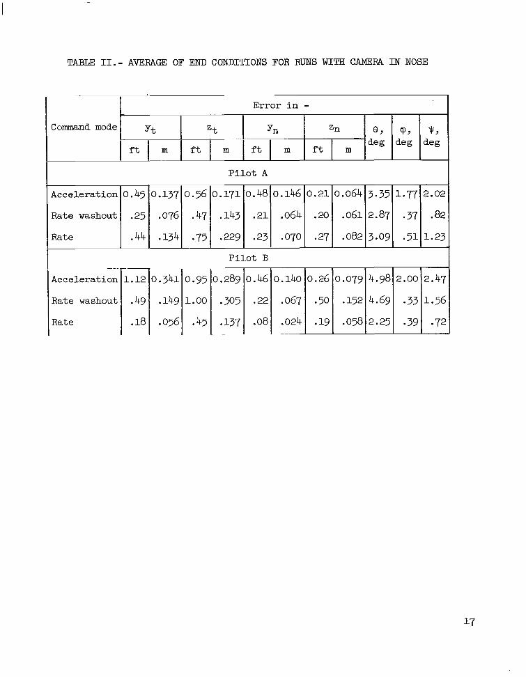
TABLE 11.- AVERAGE OF END CONDITIONS FOR RUNS WITH CAMERA I N NOSE
yt % Yn Command mode
ft m ft m ft m
Zn 0 , 9 9 $9
deg deg deg ft m
Pilot A
Acceleration 0.45 0.137 0.56 0.171 0.48 0.146
Rate washout .25 .076 .47 -143 .21 ,064
Rate .44 .134 .75 .229 .23 ,070
0.21 0.064
.20 .061
.27 .082
~~
Acceleration
Rate washout
Rate
1.12
* 49
.18
0.95 1.00
.45
Pilot B
* 137
0.140
.067
.024
0.26 0.079 5

TABLE 111. - AVERAGES OF INPUTS, FUEL, AND TIME FOR FLIGHTS MADE WITH CAMERA I N NOSE
Total average
inputs per run
Average inputs per run for : I 1 Average f l i g h t
time, s Control mode I
Average t r ans l a t ion f u e l per run
lb kg
Average Average a t t i t u d e t o t a l
f u e l per run f u e l per run
lb kg 1b kg
P i l o t A
Acceleration 6.86 6.17 4.13 14.88 16.75 24.38 73.17 185.49 0.62 0.28 1.03 0.47 1.62 0.74
Rate washout 8.88 19.63 18.38 15.25 7.00 16.13 82.27 208.71 1.84 .84 .91 .41 2.72 1.23
Rate 8.01 33.00 24.00 13.50 4.38 16.13 99.02 , 202.29 , 3.30, 1.49 , 1.61, .73 , 4.92,2.23 ,
65.80
69.08
Acceleration 2.14 ll.13 I 209.27
215.90 Rate
P i l o t B
75.35 ~ 1 216142 1.54 0.69 0.59 0.268 2.13 0.967 11 4.851 2.20 I 1.971 .8g4 I 6.8213.09 ,

Figure 1.- Translation coordinates used in CCTV study.

Figure 2.- Langley rendezvous docking simulator (Gemini configuration). L-64-4307
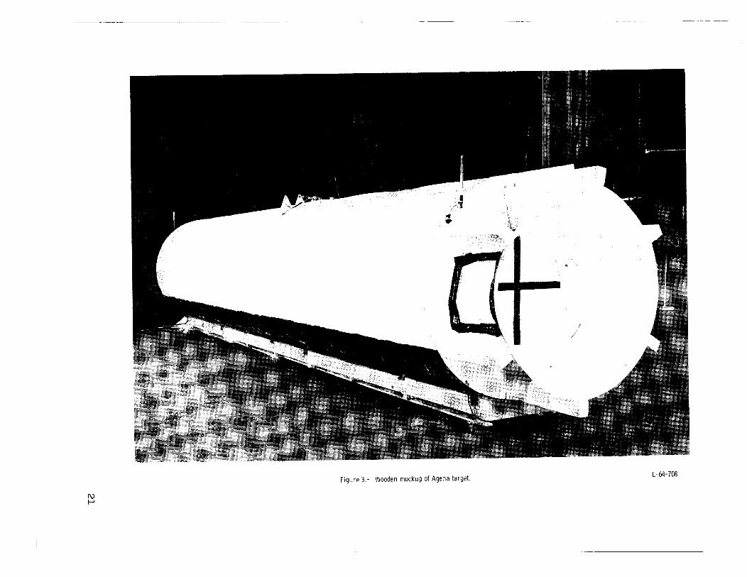
Figure 3. - Wooden mockup of Agena target. L- 64- 708

Figure 4.- Pilot position dur ing docking simulation. L-63-10153

Iu w L-63-10145 F igu re 5.- CCTV camera i n le f t side of Gemin i model cockpit.

L-63-10147 Figure 6.- CCTV camera in Gemini model nose,

Figure 7.- Inflatable planetarium. L-61-3399

Figure 8.- Attitude controller. L-63-10149

Figure 9.- Translation controller. L-63-10151

Symbol Va lue , i n c h e s P i a b
d e f €. h k 1 m n
c
.75 1 .oo
.50 14.25
.75
.25 2 .oo 8.50 3.90
1 3 . 2 5 5 . 3 0 4.70
h
k
F igu re 10.- Cross-sectional drawing of visual aid.

Ag en a t a r g e t
(a) Cutaway drawing ot v isual aid mounted in docking cone of Agena model.
Figure 11.- Views of v isual aid ( t runcated cone) used for docking w i t h TV camera in nose.

(b) View of visual aid as seen by CCTV camera.
Figure 11.- Concluded.
L-63-10152

yn, f t (m)
0 P i l o t i n cockpi t
[7 Camera i n cockpi t
( .3048) ' t z f t (m) n'
(a) P i lo t A.
0 P i l o t in cockpi t
Camera i n cockpi t I
( .3048) lt
zn, f t (m)
(b) Pilot 6.
Figure 12.- Lateral and vert ical e r ro r of center of Gemini nose with respect to Agena center l ine.
I w P

w Iu
Figure 13.- Drawing of vehicles p r i o r to docking.
Agena

0 P i l o t in cockpit
0 - - - - - - - Camera in cockpit
4.0 - - 1 . 8 2
I 3 .2 I-
2 . 4 )-
1.6
.8
0 0
e
P i l o t in cockpit 0
0 Camera i n cockpit - - - - - - -
4.0 -
3 . 2 -
2 . 4 '-
/ I3 ,. O 4 a / m
1 . 3 6
/
I 1 0 0 ' I
100
t , s
(a) Pilot A.
200 0 100
t , s
(b) Pilot 8.
1 .82
1.45
1.09
.73
.36
0 200
Figure 14.- End-condition plots of total fuel used (pounds (kg)) plotted against f l ight t ime (seconds) for pilot in cockpit and camera in cockpit.
w w

I I I I I 1111l11111llllllIIIl I
“The aeronautical and space activities of the United States shall be conducted so as to contribute . . . to the expansion of human Knowl- edge of phenomena in the atmosphere and space. The Administration shall provide for the widest practicable and appropriate dissemination of information concerning its activities and the results thereof .”
-NATIONAL AERONAUTICS AND SPACE ACT OF 1358
NASA SCIENTIFIC AND TECHNICAL PUBLICATIONS
TECHNICAL REPORTS: important, complete, and a lasting contribution to existing knowledge.
TECHNICAL NOTES: of importance as a contribution to existing knowledge.
TECHNICAL MEMORANDUMS: Information receiving limited distri- bution because of preliminary data, security classification, or other reasons.
CONTRACTOR REPORTS: Technical information generated in con- nection with a NASA contract or grant and released under NASA auspices.
TECHNICAL TRANSLATIONS: Information published in a foreign language considered to merit NASA distribution in English.
TECHNICAL REPRINTS: Information derived from NASA activities and initially published in the form of journal articles.
SPECIAL PUBLICATIONS: Information derived from or of value to NASA activities but not necessarily reporting the results .of individual NASA-programmed scientific efforts. Publications include conference proceedings, monographs, data compilations, handbooks, sourcebooks, and special bibliographies.
Scientific and technical information considered
Information less broad in scope but nevertheless
Details on the avai labi l i ty o f these publications may be obtained from:
SCIENTIFIC AND TECHNICAL INFORMATION DIVISION
NATIONAL AERONAUTICS AND SPACE ADMINISTRATION
Washington, D.C. PO546