removal and installation - 2a - removal
TRANSCRIPT
Removal
90-8M0086018 AUGUST 2013 Page 2A-1
2A
Removal and InstallationSection 2A - Removal
Table of Contents
Preparation........................................................................ 2A-2Engine Mounts................................................................... 2A-2
Front Engine Mounts.................................................. 2A-2Rear Engine Mounts................................................... 2A-3Sterndrive (MCM) Rear Engine Mount Change..........2A-3
Disconnecting the Fluid Systems.......................................2A-3Fuel Hose................................................................... 2A-3Steering Hoses........................................................... 2A-4
Seawater Hoses......................................................... 2A-4Gear Lube Monitor......................................................2A-5Oil Drain Hose (if Equipped)....................................... 2A-6
Disconnecting the Throttle Cable.......................................2A-6Disconnecting the Shift Cable............................................2A-6Disconnecting the Electrical Components......................... 2A-7Continuity Wire Removal................................................... 2A-8Removing the Engine.........................................................2A-9
Removal
Page 2A-2 90-8M0086018 AUGUST 2013
Preparation1. Remove the boat from the water.
! WARNINGPerforming service or maintenance without first disconnecting the battery can cause product damage, personal injury, ordeath due to fire, explosion, electrical shock, or unexpected engine starting. Always disconnect the battery cables from thebattery before maintaining, servicing, installing, or removing engine or drive components.
! CAUTIONDisconnecting or connecting the battery cables in the incorrect order can cause injury from electrical shock or can damagethe electrical system. Always disconnect the negative (‑) battery cable first and connect it last.
2. Disconnect the battery cables from the battery.NOTE: The sterndrive must be removed before removing the engine.
3. Remove the sterndrive. (Refer to the appropriate sterndrive service manual.)4. Remove the engine cover.
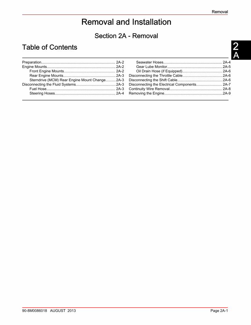
Engine MountsFront Engine Mounts
a - Bracketb - Studc - Nutd - Base assemblye - Bottom jam nutf - Tab washerg - Screwh - Lockwasheri - Top jam nut
a
b
c
d
e
f
g
h
53430
i
Removal
90-8M0086018 AUGUST 2013 Page 2A-3
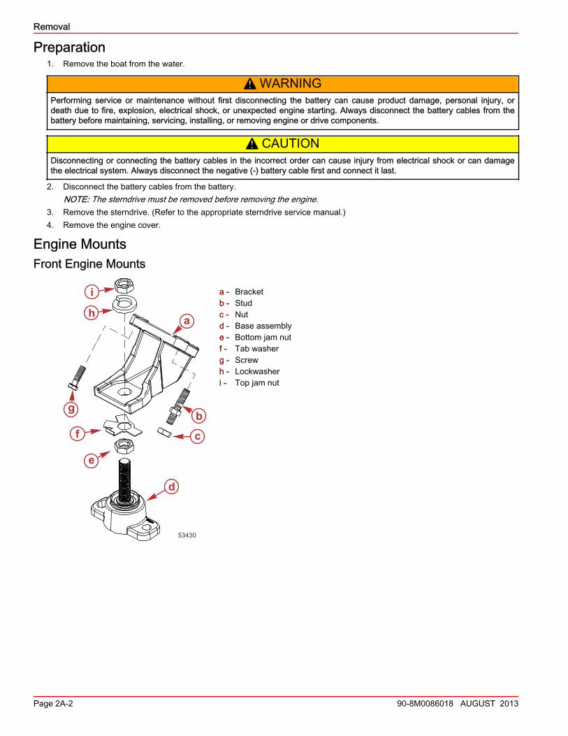
Rear Engine Mounts
Rear engine mount with lockwashera - Rear engine mountb - Inner transom plate mountc - Boltd - Washere - Spacerf - Fiber washerg - Double‑wound lockwasher
Rear engine mount withoutlockwasher and with knurled edgeon bottom
a - Painted end (not visible)b - Mount bottomc - Knurled edge
Sterndrive (MCM) Rear Engine Mount ChangeStarting serial number: 0M660000Do not use double‑wound lockwashers on the inner transom plate with rear mounts that have a knurled edge.
Disconnecting the Fluid SystemsFuel Hose
! WARNINGFuel is flammable and explosive. Ensure that the key switch is off and the lanyard is positioned so that the engine cannotstart. Do not smoke or allow sources of spark or open flame in the area while servicing. Keep the work area well ventilatedand avoid prolonged exposure to vapors. Always check for leaks before attempting to start the engine, and wipe up anyspilled fuel immediately.
1. Close the fuel shut‑off valve, if equipped.2. Loosen the hose clamp retaining the fuel line to the fuel inlet.3. Disconnect and plug the fuel line to prevent fuel in the line from leaking into the bilge.
a
c
b
d
g
f
e
13957
16836
b
a
c
Removal
Page 2A-4 90-8M0086018 AUGUST 2013
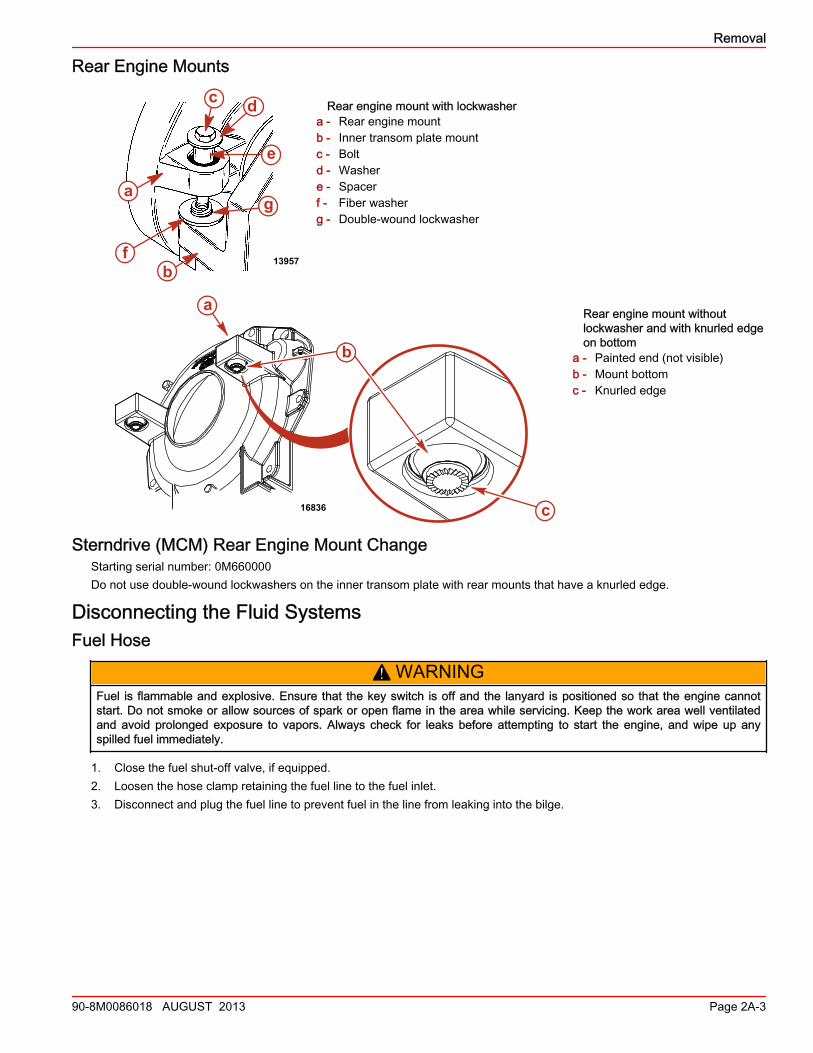
Steering Hoses1. Disconnect the hydraulic hoses from the steering actuator.
Typical power-assisted steering connectionsa - Hydraulic hosesb - Power‑assisted steering actuator
2. Plug or cap all open fittings to prevent contamination and loss of fluid.
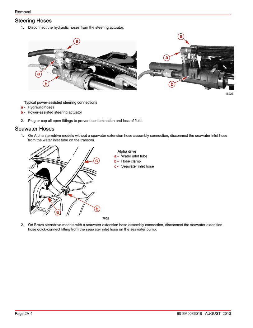
Seawater Hoses1. On Alpha sterndrive models without a seawater extension hose assembly connection, disconnect the seawater inlet hose
from the water inlet tube on the transom.
Alpha drivea - Water inlet tubeb - Hose clampc - Seawater inlet hose
2. On Bravo sterndrive models with a seawater extension hose assembly connection, disconnect the seawater extensionhose quick‑connect fitting from the seawater inlet hose on the seawater pump.
a
b
a
b
a
a
16225
a b
c
7802
Removal
90-8M0086018 AUGUST 2013 Page 2A-5
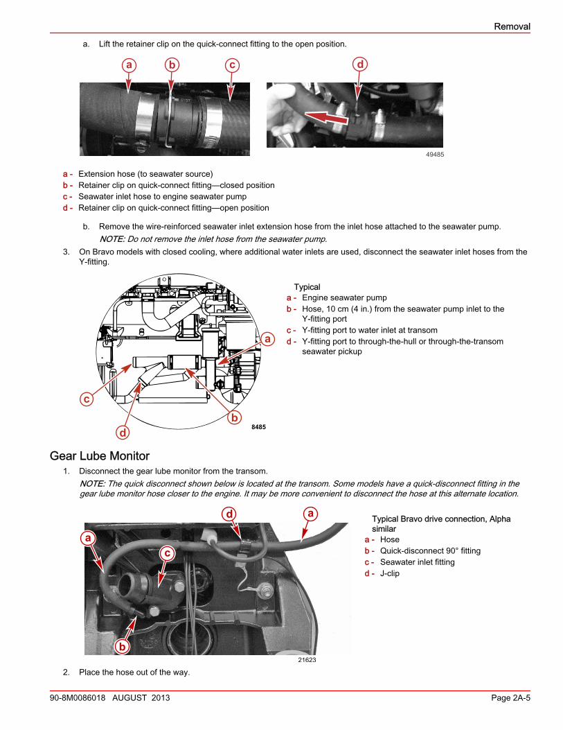
a. Lift the retainer clip on the quick‑connect fitting to the open position.
a - Extension hose (to seawater source)b - Retainer clip on quick‑connect fitting—closed positionc - Seawater inlet hose to engine seawater pumpd - Retainer clip on quick‑connect fitting—open position
b. Remove the wire‑reinforced seawater inlet extension hose from the inlet hose attached to the seawater pump.NOTE: Do not remove the inlet hose from the seawater pump.
3. On Bravo models with closed cooling, where additional water inlets are used, disconnect the seawater inlet hoses from theY‑fitting.
Typicala - Engine seawater pumpb - Hose, 10 cm (4 in.) from the seawater pump inlet to the
Y‑fitting portc - Y‑fitting port to water inlet at transomd - Y‑fitting port to through‑the‑hull or through‑the‑transom
seawater pickup
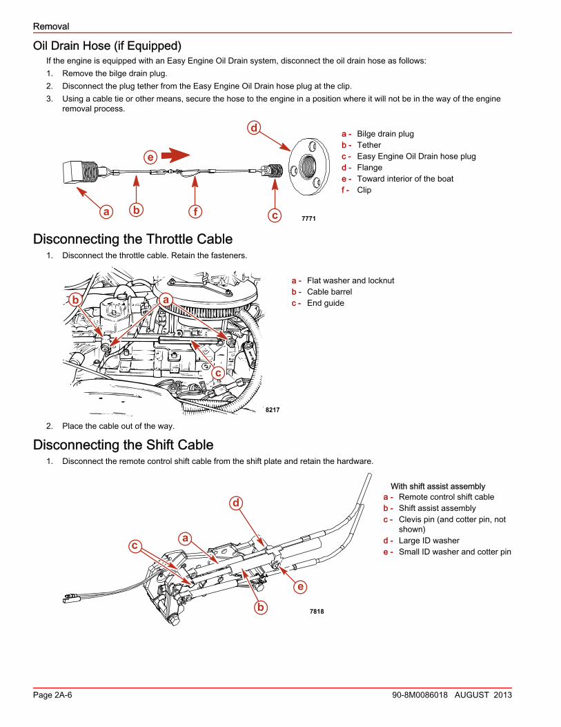
Gear Lube Monitor1. Disconnect the gear lube monitor from the transom.
NOTE: The quick disconnect shown below is located at the transom. Some models have a quick‑disconnect fitting in thegear lube monitor hose closer to the engine. It may be more convenient to disconnect the hose at this alternate location.
Typical Bravo drive connection, Alphasimilar
a - Hoseb - Quick‑disconnect 90° fittingc - Seawater inlet fittingd - J‑clip
2. Place the hose out of the way.
ba c
49485
d
a
bc
d 8485
a
a
b
c
d
21623
Removal
Page 2A-6 90-8M0086018 AUGUST 2013
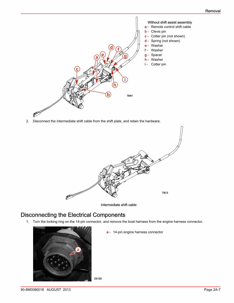
Oil Drain Hose (if Equipped)If the engine is equipped with an Easy Engine Oil Drain system, disconnect the oil drain hose as follows:1. Remove the bilge drain plug.2. Disconnect the plug tether from the Easy Engine Oil Drain hose plug at the clip.3. Using a cable tie or other means, secure the hose to the engine in a position where it will not be in the way of the engine
removal process.
a - Bilge drain plugb - Tetherc - Easy Engine Oil Drain hose plugd - Flangee - Toward interior of the boatf - Clip
Disconnecting the Throttle Cable1. Disconnect the throttle cable. Retain the fasteners.
a - Flat washer and locknutb - Cable barrelc - End guide
2. Place the cable out of the way.
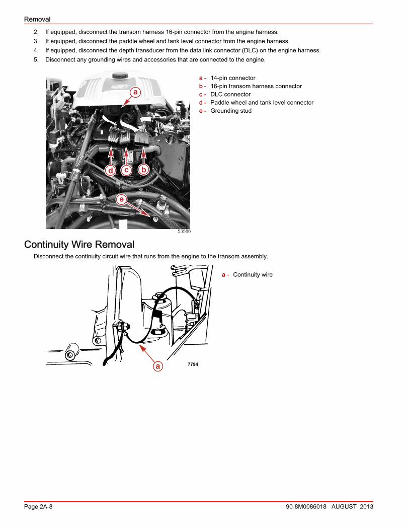
Disconnecting the Shift Cable1. Disconnect the remote control shift cable from the shift plate and retain the hardware.
With shift assist assemblya - Remote control shift cableb - Shift assist assemblyc - Clevis pin (and cotter pin, not
shown)d - Large ID washere - Small ID washer and cotter pin
c
d
e
a b f7771
c
b
8217
a
a
b
c
e
d
7818
Removal
90-8M0086018 AUGUST 2013 Page 2A-7
Without shift assist assemblya - Remote control shift cableb - Clevis pinc - Cotter pin (not shown)d - Spring (not shown)e - Washerf - Washerg - Spacerh - Washeri - Cotter pin
2. Disconnect the intermediate shift cable from the shift plate, and retain the hardware.
7813
Intermediate shift cable
Disconnecting the Electrical Components1. Turn the locking ring on the 14‑pin connector, and remove the boat harness from the engine harness connector.
a - 14‑pin engine harness connector
c
7841
a gfd
e
b
hi
23135
a
Removal
Page 2A-8 90-8M0086018 AUGUST 2013
2. If equipped, disconnect the transom harness 16‑pin connector from the engine harness.3. If equipped, disconnect the paddle wheel and tank level connector from the engine harness.4. If equipped, disconnect the depth transducer from the data link connector (DLC) on the engine harness.5. Disconnect any grounding wires and accessories that are connected to the engine.
a - 14‑pin connectorb - 16‑pin transom harness connectorc - DLC connectord - Paddle wheel and tank level connectore - Grounding stud
Continuity Wire RemovalDisconnect the continuity circuit wire that runs from the engine to the transom assembly.
a - Continuity wire
a
bcd
e
53586
a 7794
Removal
90-8M0086018 AUGUST 2013 Page 2A-9
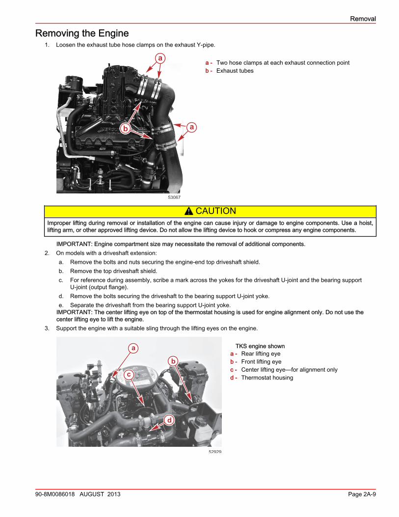
Removing the Engine1. Loosen the exhaust tube hose clamps on the exhaust Y‑pipe.
a - Two hose clamps at each exhaust connection pointb - Exhaust tubes
! CAUTIONImproper lifting during removal or installation of the engine can cause injury or damage to engine components. Use a hoist,lifting arm, or other approved lifting device. Do not allow the lifting device to hook or compress any engine components.
IMPORTANT: Engine compartment size may necessitate the removal of additional components.2. On models with a driveshaft extension:
a. Remove the bolts and nuts securing the engine‑end top driveshaft shield.b. Remove the top driveshaft shield.c. For reference during assembly, scribe a mark across the yokes for the driveshaft U‑joint and the bearing support
U‑joint (output flange).d. Remove the bolts securing the driveshaft to the bearing support U‑joint yoke.e. Separate the driveshaft from the bearing support U‑joint yoke.
IMPORTANT: The center lifting eye on top of the thermostat housing is used for engine alignment only. Do not use thecenter lifting eye to lift the engine.
3. Support the engine with a suitable sling through the lifting eyes on the engine.
TKS engine showna - Rear lifting eyeb - Front lifting eyec - Center lifting eye—for alignment onlyd - Thermostat housing
a
ab
53067
a
b
c
d
52929
Removal
Page 2A-10 90-8M0086018 AUGUST 2013
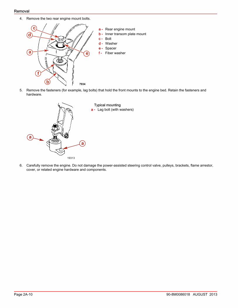
4. Remove the two rear engine mount bolts.
a - Rear engine mountb - Inner transom plate mountc - Boltd - Washere - Spacerf - Fiber washer
5. Remove the fasteners (for example, lag bolts) that hold the front mounts to the engine bed. Retain the fasteners andhardware.
Typical mountinga - Lag bolt (with washers)
6. Carefully remove the engine. Do not damage the power‑assisted steering control valve, pulleys, brackets, flame arrestor,cover, or related engine hardware and components.
7934
a
cd
f
e
b
19313
aa