[removal of power line interference and other single ... · msc thesis report, mälardalen...
TRANSCRIPT

Removal of Power Line Interference and other Single Frequency Tones from Signals
MSc Thesis Report, Mälardalen University, Sweden 1
MSc ThesisMSc ThesisMSc ThesisMSc Thesis REPORT REPORT REPORT REPORT
LEVEL: 20 P, DLEVEL: 20 P, DLEVEL: 20 P, DLEVEL: 20 P, D----LEVELLEVELLEVELLEVEL
A report submitted to the Department of Computer Science and Electronics, Mälardalen University, A report submitted to the Department of Computer Science and Electronics, Mälardalen University, A report submitted to the Department of Computer Science and Electronics, Mälardalen University, A report submitted to the Department of Computer Science and Electronics, Mälardalen University,
in part fulin part fulin part fulin part fulfilment of the Degree of Master of Science in filment of the Degree of Master of Science in filment of the Degree of Master of Science in filment of the Degree of Master of Science in
Electronics with Biomedical EngineeringElectronics with Biomedical EngineeringElectronics with Biomedical EngineeringElectronics with Biomedical Engineering
By
Sheeraz Gul Tareen [email protected]
Tutor:
Mikael Ekström
Supervisor:
Prof. Rashid Baig
www.mdh.se
Department of Computer
Science and Electronics
08
[Removal of Power Line Interference and
other Single Frequency Tones from Signals]

Removal of Power Line Interference and other Single Frequency Tones from Signals
MSc Thesis Report, Mälardalen University, Sweden 2
Table of Contents
DEDICATION ___________________________________________________________ 7
ACKNOWLEDGEMENTS___________________________________________________ 8
ABSTRACT _____________________________________________________________ 9
1 CHAPTER-1 ________________________________________________________ 10
1.1 Problem Description ___________________________________________________ 10
1.2 The Purpose of Thesis __________________________________________________ 10
1.3 Report Layout ________________________________________________________ 11 1.3.1 Chapter-1 ________________________________________________________________ 11 1.3.2 Chapter-2 ________________________________________________________________ 11 1.3.3 Chapter-3 ________________________________________________________________ 11 1.3.4 Chapter-4 ________________________________________________________________ 11 1.3.5 Chapter-5 ________________________________________________________________ 11 1.3.6 Chapter-6 ________________________________________________________________ 12 1.3.7 Chapter-7 ________________________________________________________________ 12 1.3.8 Chapter-8 ________________________________________________________________ 12 1.3.9 References _______________________________________________________________ 12
2 CHAPTER-2 ________________________________________________________ 13
2.1 General Overview _____________________________________________________ 13 2.1.1 Heart Mechanism and Purpose of ECG Diagnosis ________________________________ 14
2.2 Background and Motivations.____________________________________________ 15
2.3 Thesis Specifications. __________________________________________________ 16
2.4 Thesis Aims and Objectives. _____________________________________________ 16
2.5 The Choice for MATLAB Software_________________________________________ 17
3 CHAPTER-3 ________________________________________________________ 18
3.1 Digital Signal Processing (DSP) ___________________________________________ 18
3.2 What are Filters_______________________________________________________ 18
3.3 What are Digital Filters? ________________________________________________ 19
3.4 Advantages of Digital Filters _____________________________________________ 19
3.5 Types of Digital Filters__________________________________________________ 20
3.6 Computational Properties and structure of Digital Filters Algorithm_____________ 21

Removal of Power Line Interference and other Single Frequency Tones from Signals
MSc Thesis Report, Mälardalen University, Sweden 3
3.7 DIGITAL FILTER ORDER, STEP-SIZE AND COEFFICIENTS ________________________ 22 3.7.1 Order of a Digital Filter _____________________________________________________ 22 3.7.2 Step-Size of a Digital Filter __________________________________________________ 23 3.7.3 Coefficient of the Digital Filter._______________________________________________ 23
4 CHAPTER-4 ________________________________________________________ 24
4.1 Introduction__________________________________________________________ 24
4.2 Explanation of Adaptive Filter ___________________________________________ 24
4.3 Adaptive Filters and Digital Signal Processing _______________________________ 25
4.4 Adaptive Filtering _____________________________________________________ 25
4.5 The General Structure of Adaptive Filters __________________________________ 26
4.6 Performance, Stability and Robustness of the Adaptive Algorithm ______________ 27
4.7 Convergence Criteria for Adaptive Algorithm _______________________________ 28
4.8 System Identification Configuration Using an Adaptive Filter __________________ 29
5 CHAPTER-5 ________________________________________________________ 31
5.1 Introduction__________________________________________________________ 31
5.2 Advantages of Filters and Adaptive Algorithm ______________________________ 31
5.3 Finite Impulse Response (FIR)____________________________________________ 32
5.4 FIR Filters Advantages and Disadvantages__________________________________ 33 5.4.1 Advantages: ______________________________________________________________ 33 5.4.2 Disadvantages:____________________________________________________________ 33
5.5 Comparison between FIR and IIR Filters ___________________________________ 33
5.6 Adaptive FIR Signal Processor____________________________________________ 34
6 CHAPTER-6 ________________________________________________________ 36
6.1 Adaptive Filter Algorithms ______________________________________________ 36
6.2 Introduction to LMS Algorithm___________________________________________ 36
6.3 Overview of the Structure and Operation of the LMS Algorithm ________________ 37
6.4 Design of an Adaptive Filter Algorithm ____________________________________ 38
6.5 Noise Cancellation_____________________________________________________ 39
6.6 Adaptive Noise Cancellation_____________________________________________ 41
6.7 Interference Cancellation by Adaptive Filtering _____________________________ 42
7 CHAPTER-7 ________________________________________________________ 44
7.1 Main Objective _______________________________________________________ 44
7.2 Design by DSP Technique _______________________________________________ 45
Removal of Power Line Interference and other Single Frequency Tones from Signals
MSc Thesis Report, Mälardalen University, Sweden 4
7.3 MATLAB Software Implementation _______________________________________ 45
7.4 Verification for Refinement of Signal by LMS _______________________________ 46 7.4.1 Removal of Power Line Interference (50 Hz) from ECG Signal by LMS Algorithm _______ 46 7.4.2 Removing of Harmonics and High Frequency Noise from Original ECG Signal __________ 51
7.5 Algorithm Implementation and Verification ________________________________ 53
8 CHAPTER-8 ________________________________________________________ 55
8.1 CONCLUSION AND FUTURE RESEARCH_____________________________________ 55 8.1.1 Conclusion _______________________________________________________________ 55 8.1.2 Suggestion for Future Work/Future Enhancement _______________________________ 56
9 APPENDIX A _______________________________________________________ 57
9.1 MATLAB CODE FOR ECG SIGNAL__________________________________________ 57
10 APPENDIX C _______________________________________________________ 61
10.1 MATLAB CODE FOR HARMONICS AND HIGH FREQUENCY NOISES FROM ECG SIGNAL
BY GENERAL NOTCH REJECTION FILTER _________________________________________ 61
11 REFERENCES _______________________________________________________ 65

Removal of Power Line Interference and other Single Frequency Tones from Signals
MSc Thesis Report, Mälardalen University, Sweden 5
List of Figures
FIGURE 21 – ECG signal with QRS complex _________________________________ 14
FIGURE 4.1 – Principle of an Adaptive Filter ________________________________ 26
FIGURE 4.2 – The general structure of an adaptive filter ______________________ 27
FIGURE 4.3 – System Identification Configuration for Adaptive Filter ____________ 29
FIGURE 5.1 – FINITE IMPULSE RESPONSE (FIR) FILTER STRUCTURE ____________________ 34
FIGURE 5.2– The Adaptive Signal Processor________________________________ 38
FIGURE 6.1 – LMS ADAPTIVE ALGORITHM _____________________________________ 37
FIGURE 6.2 – OUTLINE OF ADAPTIVE TRANSVERSAL FILTER __________________________ 39
FIGURE 6.3 – NOISE CANCELLATION EXAMPLE___________________________________ 40
FIGURE 6.4 – BLOCK DIAGRAM OF ADAPTIVE NOISE CANCELLER_______________________ 41
FIGURE 6.5 – INTERFERENCE CANCELLATION BY ADAPTIVE FILTERING____________________ 42

Removal of Power Line Interference and other Single Frequency Tones from Signals
MSc Thesis Report, Mälardalen University, Sweden 6
“Mind is not a vessel to be filled, but a fire to be kindled.”

Removal of Power Line Interference and other Single Frequency Tones from Signals
MSc Thesis Report, Mälardalen University, Sweden 7
DEDICATION
“I owe immense sense of gratitude to my beloved
Parents and family members who supported me financially as well
as morally, throughout my career. I also dedicate the thesis to my
university teachers who remained the source of encouragement
throughout.” Finally, I would like to thanks my sister ‘Nasreen
Akhtar’ who is educationist, friend ‘Noor’ who is doctor and all
other friends for their support and encouragement during the
critical time to finish this greatest task of my life.

Removal of Power Line Interference and other Single Frequency Tones from Signals
MSc Thesis Report, Mälardalen University, Sweden 8
ACKNOWLEDGEMENTS
I start with the name of Almighty Allah for providing me with the
unique opportunity to finalise this thesis.
It would not have been possible for me to complete this thesis
“Removal of Power Line Interference and other Single Frequency
Tones from Signals”,
except for the able guidance and constructive suggestions of my
thesis supervisor (Prof. Rashid Baig), thesis tutors (Mikael
Ekström). Their supervision and encouragement has made it
possible for me to complete this task, which is very important for
practical work.
Removal of Power Line Interference and other Single Frequency Tones from Signals
MSc Thesis Report, Mälardalen University, Sweden 9
ABSTRACT
Removal of Power Line Interference and other Single Frequency Tones from
Signals
With the latest advancements in electronics, several techniques are used for removal of
unwanted entities from signals especially that are implied in the most sophisticated
applications. The removal of power line interference from most sensitive medical
monitoring equipments can also be removed by implementing various useful
techniques. The power line interference (50/60 Hz) is the main source of noise in most
of bio-electric signals. The thesis report presents the removal of power line interference
and other single frequency tones from ECG signal using the advanced adaptive filtering
technique with LMS (least mean square) algorithm. The thesis is based on digital signal
processing (DSP) techniques with MATLAB package, with the emphases on design of
adaptive LMS algorithm. The adaptive interference removal technique can be used for
removal of power line interference in various potential applications such as recording
Electrocardiograms (ECG), Electroencephalogram (EEG) and Electromyogram (EMG).
MATLAB package will be used in the thesis work which is a powerful tool for the
interactive design in most of the scientific applications and complex engineering
calculations.
As an additional in order to achieve the goal of thesis it will also be investigated and
implemented for the removal of harmonics (hum) and high frequency noise from ECG
signal by using general notch rejection filters, which are partial milestone for the thesis.
Removal of Power Line Interference and other Single Frequency Tones from Signals
MSc Thesis Report, Mälardalen University, Sweden 10
1 CHAPTER-1
THESIS INTRODUCTION
1.1 Problem Description
The medical monitoring devices are more sensitive for the biomedical signal recording
and need more accurate results for every diagnosis. It is complicated to get accurate
result for every biomedical signal’s recording while patient is diagnosis by medical
monitoring equipments such as ECG, EEG and EMG.
The low frequency signal is destroyed by power line interference of 50/60 Hz noise, this
noise is also source of interference for biomedical signal recording. The signal can also
be corrupted by electromagnetic field (EMF) by the machinery which is placed nearby.
[1] The frequency of power line interference 50/60 Hz is nearly equal to the frequency
of ECG, so this 50/60 Hz noise can destroyed the output of ECG signal while the patient
is diagnosis at hospital or some where else. The recording of ECG signal can not give
accurate result due to the power supply or by environment. [1]
There are many reasons for the corruption of ECG signal while recording in hospital or
some other place due to the external interference which comes from power
transformer or high voltage electric power lines and internal interference comes from
the internal power supplies. Other problem occurs by harmonics and high frequency
noises. In a noise signal, the signal component holds harmonics with different amplitude
and frequency. The harmonics frequency is integral multiple of fundamental frequency
such as 50Hz. Due to these interferences the quality of ECG signal can not be ideal so it
is needed to improve the quality of required output of ECG signal.
1.2 The Purpose of Thesis
The fundamental purpose of this thesis is to remove 50/60 Hz noise and other single
frequency tones from ECG signal by the designing and implementation of least mean
square (LMS) algorithm based upon the FIR filters using MATLAB environment. The
additional milestone of the thesis is to investigation and implementation of the removal
of harmonics and high frequency noise by using general notch rejection filters from ECG
signal in MATLAB environment.
Removal of Power Line Interference and other Single Frequency Tones from Signals
MSc Thesis Report, Mälardalen University, Sweden 11
1.3 Report Layout
This section provides a summary of the all the chapters covered in this report.
1.3.1 Chapter-1
This chapter gives the introduction to the thesis, the problem description, purpose and
also detail of report layout of the thesis report.
1.3.2 Chapter-2
This chapter provides the details of problem of power line interference in ECG. And also
present the general overview, heart mechanism & purpose of ECG diagnosis, description
of the thesis, details of the background and motivation, thesis specifications, aim &
objectives of the thesis and this chapter also contain why using MATLAB package.
1.3.3 Chapter-3
This chapter details the basic theory of digital filters, digital signal processing, what are
filters & digital filters, advantages of digital filters, categories of digital filters,
computational property & structure of digital filters algorithm and also contains an
overview on the digital filter’s order, step-size & coefficient.
1.3.4 Chapter-4
This chapter provides the introduction of adaptive filters and its explanation. It also
provides the detail of adaptive filters with respect to digital signal processing, adaptive
filtering concept, general structure for adaptive filtering and performance, stability and
robustness of adaptive algorithm. This chapter also gives the details of convergence
criteria and system identification configuration using an adaptive filter.
1.3.5 Chapter-5
This chapter provides the introduction to adaptive algorithm, advantages of adaptive
filters and adaptive algorithm, FIR filters details, its advantages and disadvantages. It
also gives a brief comparison of the two filters and why the FIR filters and LMS algorithm
is best suited for this thesis. It also gives the brief description of the filtering solution for
removal of power line AC interference and adaptive FIR filter processor.

Removal of Power Line Interference and other Single Frequency Tones from Signals
MSc Thesis Report, Mälardalen University, Sweden 12
1.3.6 Chapter-6
This chapter presents the brief description of adaptive filter algorithm and the least
mean square (LMS) algorithm which is to be employed in this thesis to perform the
noise cancellation. It also gives the overview of the structure & operation of the LMS
algorithm, the design of adaptive filter algorithm, noise cancellation adaptive noise
cancelation and interference cancellation.
1.3.7 Chapter-7
In this chapter the design, analysis and simulation results are described. It also give the
details of main objective & how design by DSP technique and the technique of software
implementation & verification for refinement for signal by LMS, which includes removal
of power line interference from ECG signal & removal of power line interference from
voice signal and also described its simulation results. It also gives the detail and graphs
of removing of humming and high frequency noise from ECG signal. Finally the algorithm
implementation and verification has been presented.
1.3.8 Chapter-8
This chapter provided the conclusion and future research. It also gives the detail of the
thesis goal, its achievement and what has been concluded after completion this thesis.
1.3.9 References
The list of information gathered from books, university library database, journals and
internet sites.

Removal of Power Line Interference and other Single Frequency Tones from Signals
MSc Thesis Report, Mälardalen University, Sweden 13
2 CHAPTER-2
INTRODUCTION TO ECG SIGNAL WITH POWER LINE INTERFERENCE
2.1 General Overview
The electric power lines are main source of electricity transportation from grid station to
the consumers. Power transformers are used for the transform of voltage which is
generated from the grid station.
The purpose of electricity generation is for the powering electronic & electrical
technologies acquired from various sources of energy. The source of energy for first
power plant was wood, while today it relies mainly on coal, nuclear energy, natural gas,
hydroelectric and petroleum geothermal sources. [2]
Due to the large amount of power involved, transmission normally takes place at high
voltages (110 kV or above). Electricity is usually transmitted over long distance through
overhead power transmission lines. Most transmission lines operate with three-phase
alternating current (AC). The standard frequency in North America is 60 Hz; while 50 Hz
in rest of world.
The power line interference 50/60 Hz is the source of interference in bio potential
measurement and it corrupt the biomedical signal’s recordings such as
Electrocardiogram (ECG), the Electroencephalogram (EEG) and the Electromyography
(EMG) which are extremely important for the diagnosis of patients. It is hard to find out
the problem because the frequency range of ECG signal is nearly same as the frequency
of power line interference.
The figure 2.1 shows the one period of uncorrupted ECG signal with QRS complex. The
ECG signal contains the information within the frequency range of around 50 Hz that is
why it is called QRS complex. The QRS complex is a waveform which is most important
in all ECG’s waveforms and it comes into view in usual and unusual signals in an ECG. [3]

Removal of Power Line Interference and other Single Frequency Tones from Signals
MSc Thesis Report, Mälardalen University, Sweden 14
Figure 2.1- ECG signal with QRS complex [3]
Adaptive filters are used to eliminate the power line interference (60 Hz) and they are
proposed to obtain the impulse response of the normal QRS complex. [4] In the figure
above, an uncorrupted ECG signal shows an original signal graph for ECG signal which
demonstrate the diagnosis of heart activities for heart patient.
Consequently, it is analysis that how to remove the power line interference of 50/60 Hz
which is a problem for biomedical signal measurement. Electromagnetic interface (EMI)
from 50/60 Hz power line noise is present in cable holding ECG signal. [5]
Several solutions for the removal of power line interference have been expressed. The
main source of interference is AC power line interference. The interference is caused by
magnetic fields as well as by the electric fields. When special signal recording techniques
are applied, which minimize the interference therefore some AC noise remains as a
consequence of unbalanced input impedances. Further removal of AC noise must be
accomplished either by analog or digital filters.
2.1.1 Heart Mechanism and Purpose of ECG Diagnosis
The heart is a muscular organ, it pump the blood throughout the body and collecting
blood circulating back from the body. [6] Electrical impulses are the main source of
generation of regular normal heartbeat. The heart muscle must be activated electrically
before the beginning of its mechanical function. When the electrical abnormalities of
the heart occur then the heart cannot pump blood properly and supply enough to the
Removal of Power Line Interference and other Single Frequency Tones from Signals
MSc Thesis Report, Mälardalen University, Sweden 15
body and brain. This can cause unconsciousness within second and death within
minutes. [7]
An ECG recording is important for clinical diagnosis and treatment; it is a graphical
recording of electrical impulses generated by heart. The ECG is needed to be done when
chest pain occurred such as heart attack, shortness of breath, faster heartbeats,
irregular heartbeats, high blood pressure, high cholesterol, check the heart’s electrical
activity. [6]
2.2 Background and Motivations.
The Electrocardiograph (ECG) signal is an electrical signal generated by the heart’s beats
and can be used to examine some of the functions of the heart. The ECG signal can be
distorted with noise of 50/60 Hz and by some other sources. The noise from electric
power system is a major source of noise during the recording or monitoring of ECG. [8]
Different noises have different frequencies; the noise with low frequency is being
problem with ECG signal and some time high frequency noises also interfere ECG i.e.
mobile phone. If the physical or mathematical variable changes rapidly then it can be
high frequency and if it changes slowly then it would be low frequency. If the variable
does not change at all then it is said that it has zero frequency. The frequency is
measured in cycle/second or in "Hertz". For example the electric power used in daily life
in United State is 60 Hz and 50 Hz in the rest of world.
Most of the electronic devices such as ECG, transmitter, receiver, computer etc get
power from power line. The 50 Hz alternative current (AC) is reduced in voltage,
rectified and than filter to obtain low voltage direct current (DC). This is used to give
power to those electronic devices. [9] Numbers of adaptive filter solution had been
proposed for noise cancellation in ECG. The adaptive filter remove or reduces the mean
squared error between primary input (ECG signal) and the reference input (noise with
ECG signal) [4]
While recording ECG signal, the critical problem is unwanted noise from power line
interference. There are different noises which affect ECG signal but 50/60 Hz
interference from power line distribution is most critical and also 1 Hz power line
interference due to patient’s movement. Various methods were developed for the
removal of power line interference from last two decade. The suitable and prime
methods were based on ECG filtering. [10]
There have been different filtering solutions, which were introduced for the removal of
power line AC interference. The crucial problem of power line interference was found in
ECG signal. In this project the power line interference of 50/60 Hz is major purpose to
remove it from ECG signal. Different filtering solution has been studied to find out the

Removal of Power Line Interference and other Single Frequency Tones from Signals
MSc Thesis Report, Mälardalen University, Sweden 16
best solution for the removal of power line interference from ECG signal. Digital filter
has been selected to overcome this problem; there are few filtering solutions which
were examined before to manipulate the power line interference from signal which can
be divided into following categories. [10]
.
• Low Pass Filters
• General Notch-Rejection Filters
• Adaptive Filters
• Global filters
In the thesis two filtering solutions has been chosen for the removal of power line
interference, its respective harmonics and high frequency noise from Original ECG
signal. The removal of power line interference (50Hz) from ECG signal can be removed
by adaptive filtering while the harmonics and high frequency noise can be removed by
implementing general notch rejection filters.
2.3 Thesis Specifications.
The fundamental aim of thesis is to analyze the power line interference by starting a
simple approach from fundamentals of digital signal processing (DSP), digital filters and
then adaptive filters with LMS implementations. The power line interference, some
other signal frequency tones signals and harmonics impacts on the ECG signal which can
be described by MATLAB software simulation.
The main objective is to remove 50 Hz power line interference from ECG signal by using
LMS adaptive algorithm based upon FIR filter. The additional milestone of the project is
to remove harmonics and high frequency noises by using general notch rejection filters
and windowed sinc low pass filters. This method can be employed in a number of useful
applications in which the prime concern is to get the original ECG signal and the
contaminated entities are critically removed.
2.4 Thesis Aims and Objectives.
• To describe the power line interference, main cause of power line interference in
ECG Signal and to carry out a literature survey on removal of power line interference
from ECG signal.
• To give solution for the removal of power line interference in ECG signal and to
investigation of different methods and to point out the best possible methodology
for the removal of power line interference.
• To search for the adaptive filtering technique for removal of 50/60 Hz power line
frequency interference and to have extensive knowledge in, DSP i.e. adaptive
filtering, FIR, IIR, LMS algorithm etc
Removal of Power Line Interference and other Single Frequency Tones from Signals
MSc Thesis Report, Mälardalen University, Sweden 17
• To illustrate the suitable method or process to remove the noise, other unwanted
components, undesired tones and interferences from information signal.
• To search for the best possible method available to be used for the removal of
power line interference through the internet, journals & books and analysis of
different kind of signals using MATLAB software.
• In additional to investigate and analyze the harmonics and high frequency
interference in original ECG signal and to remove these noises by using general
notch rejection filters and windowed sinc low pass filter.
• In the project, the deductive experimental research strategy is preferable, in this
view the investigation, observation and testing to get the desired objectives can be
accomplished on the basis of experimental works and to continue the future
research and development regarding this view.
2.5 The Choice for MATLAB Software
MATLAB is commercial software product, which is available from the Mathworks. It
consist of main ‘engine’ having strong mathematical function built-in which perform the
computational and other extended-function libraries for special purpose applications.
[11]
The MATLAB software provides a variety of functions that make it easy and flexible
while simulation for interactive designing, advance analyzing, exploration and visualizing
signals, filters and windows. It provides the tools for finite impulse response (FIR) and
infinite impulse response (IIR), digital filter design, implementation and analysis. It also
provides the toolbox for application such as speech & audio processing, medical imaging
& instruction, wired & wireless communication and financial modeling & analysis. [12]-
[14]
MATLAB has set of construct for plotting scientific graphs from raw or computed data.
[11] It is a high performance language, most productive development and interactive
environment for engineering and technology implementations software package.
MATLAB enables to perform different functions which included, electronic
programming, technical computing applications, scientific & engineering graphical
illustration, accurate numerical calculation, algorithms development, application
development including graphical user interface building, graph and report or software
simulation etc. [12]- [14]

Removal of Power Line Interference and other Single Frequency Tones from Signals
MSc Thesis Report, Mälardalen University, Sweden 18
3 CHAPTER-3
BASIC THEORY OF DIGITAL FILTERS
3.1 Digital Signal Processing (DSP)
Digital signal processing (DSP) is well-known as compared to analog signal processing in
different applications. [13] The signals are time varying quantities which carry
information i.e. audio signal, video signals, biological signals (electrical pulses from the
heart) and communications signals. [11] A digital signal is define as the signal that has
discrete amplitude and time. These signals are represented by sequences of numbers
with finite precision and can be used when processing information by computer. [15]
The processing of the signals which deals with sound and images are known as Digital
Signal Processing. In DSP the digital signal processor can be a small microprocessor or a
large programmable digital computer, which perform the desired operations on the
input signal. [16] The application of Signal Processing has grown very fast and
implemented the advanced techniques in speech recognition, image recognition, image
enhancement, audio enhancement, noise reduction, speech & audio encoding and
storage, digital music, communication and data transmission, biometrics, biomedical
applications, radar, sonar and military applications. [13]–[11] Digital signal processing
systems are introduced in many different applications such as multimedia, video
recording, CD player, mobile phones, computers and modem, DSP systems acquired
famous due to their reliability, accuracy, small physical sizes and flexibility.
3.2 What are Filters
A filter is a device when a signal is given; it changes to some desired form by changing its
shape, amplitude, frequency or phase frequency. They are usually employed to remove
the noise, extract information signals and separate two or more combined signals. [17]
There are two main classes of filter, analog and digital filters. These filters are used for
different applications; the selection for the filter depends upon the required output of
the application.
Removal of Power Line Interference and other Single Frequency Tones from Signals
MSc Thesis Report, Mälardalen University, Sweden 19
3.3 What are Digital Filters?
Digital filters and signal processing systems or algorithms which are classified as
discrete-time systems and are normally implemented on a digital signal processing (DSP)
chip or special purpose hardware and software in a general purpose computer. These
software approaches are in a mean of computational structures. Analog filters are
replacing by the digital filters because of digital filter’s well known advantages and good
performance in the advanced era of communication system. [18] Digital filters are in
smaller size, much lower component tolerances, greater accuracy, greater reliability,
ability to share multiple filtering tasks than analog filters. [19]
There are two types of filters that can be design as analogue or digital filters. Digital
filters are progressively replacing analogue filter day by day. [20] The designing of the
digital filter needed to remove the unwanted noise from the original signal i.e. if the a
signal x(k) is processed in a discrete system the output signal will be y(k), if this output
signal y(k) is different from the original signal x(k) then it must be needed to modify the
system to get the required output. Then digital filter will be the solution to manipulate
this problem. [19] Digital filters are extremely used in noise cancellation, echo
cancellation and also in the field of biomedical engineering to remove unwanted noise
from ECG, EMG and EEG.
As with the advancement in the technology many signal manipulations like
multiplication, subtraction, differentiation, PID and filtering which were previously
carried out through dedicated hardware are now implemented equally well or even
better by the use of Processors (microprocessors, DSP chips, microcontrollers, CPLDs
etc).Once a signal is captured and converted through ADC, it becomes a numerical value
with certain characteristics, any kind of mathematical algorithm then can be written to
manipulate this value. After the required manipulation the desired output can be
produced using the DAC converter. Digital Filters are same as the analogue filters as far
as their functions is concerned, which is to separate a desired portion of signal
frequencies from the undesired ones but their physical realization is quite different as in
essence digital filters are different mathematical relations written in a specific algorithm
meant to be executed by computers.
3.4 Advantages of Digital Filters
The digital filters can provide many advantages; a brief summery is given below.
1 The charm of the digital filters lies in the fact that digital filters are realized in the
form of piece of software so can be adapted for any required amendment with
out any increase in cost or effort on the electronic circuit.
Removal of Power Line Interference and other Single Frequency Tones from Signals
MSc Thesis Report, Mälardalen University, Sweden 20
2 As digital filter is a programmable filter are often implemented in a computer
using a high level programming language so it can be reused if required to
produce cost effective solution. In digital filters for digital design the
characteristics of digital component do not change over time [21]
3 Plenty of support is available for design and testing of digital filters in the form of
CAD and other pre-built package on a general-purpose computer or workstation.
4 By using programmable processes it can be easily modified to change its
frequency response or other characteristic. [17]
5 Realization of the digital filters can be made using the generic hardware (PC,
DAC, ADC, CPLDs) without indulging in the design of specific hardware, which
also helps in reducing the cost and time required in this process.
6 Digital filters can be used in biomedical instruments where frequency is very low
and analog filters are unpractical. [17]
7 Digital filters are most common use in any modern communication system and
digital systems are unaffected by temperature variation. [21]
8 With the advancement in technology the digital filters can be managed at low
frequency signals precisely. The technology of the DSP is increasing very fast, so
the digital filter are applied for the high frequency signal as well i.e. RF (radio
frequency) domain, which in the past was the limited to analog technology. [22]
9 Digital filters can be seen as the direct result of the advancement made in the
computers and computing technology so it will continue to benefit from the
increase in speed and power of computing chips in the future.
10 Digital filters are small in size, consume less power and can be implemented with
less cost and it also store data for future use. [17]
11 Digital filters can made accurate processing, permits the implementation of
many different operations and become more economical. [19]
3.5 Types of Digital Filters
The most imperative tools of DSP are a digital filtering. The separations of signals are
principally utilized by electronic filters, which are combined and the refurbishment of
distorted signals that can be distorted due to the certain reasons. Digital filters are
implemented in real time, the desired output is removal of noise and they are
implemented in dedicated hardware or computer using a high level language. [17] By
Removal of Power Line Interference and other Single Frequency Tones from Signals
MSc Thesis Report, Mälardalen University, Sweden 21
the software control, digital filter can be easily changed and are well-suited to do this
task as compared to analogue filters because of their outstanding results.
The digital filters are divided into two basic types, Finite Impulse Response (FIR) and
Infinite Impulse Response (IIR) filters. [23]- [13] - [24] which are known as non recursive
and recursive filters. [25] These types of digital filters can perform paramount required
tasks yet they are categorized either as non recursive filter known as Finite Impulse
Response (FIR) filters or a recursive filter known as Infinite Impulse Response (IIR)
filters.[26]- [25] The term non recursive filter & finite impulse response (FIR) filter and
recursive filter & infinite impulse response (IIR) filter are almost synonymous. [19]. Non
recursive that as implied by the name has a finite length impulse response and recursive
that has an impulse response of infinite length. Both types of filters can be used in the
realization of the noise cancellation but an FIR filter was chosen since it is simple and
stable. [26]
The variety of design methods has been involved for the designing of digital filters to
meet different specifications. The lowest order filter is chosen to avoid the overdesign.
The choice between the filter type (recursive and non recursive) is done due to the
computational property and the storage required for the implementation.
3.6 Computational Properties and structure of Digital Filters Algorithm
The computational property of digital filters algorithm is most important for its
structure. For any digital filter structure it must be needed to work out its
computational property because the computational property of the digital filter
algorithm affect on the performance of digital filter. For the description of
computational properties of digital filter algorithm latency and throughput are used.
Latency is the time for the data flow which applied to a general digital algorithm to
reach the output. Throughput is the measurement of frequency input data applied to a
system. [21]
The structure of digital filter can be described by signal flow graph, they are used to
convert a given transfer function into computational procedure. The structure used is
depending on type of the filter. In IIR filter’s commonly used forms are direct form,
cascade form and parallel form and in FIR filters the direct form or transversal structure
is most widely used because of its ease of implementation. Two other structures are
frequency sampling and fast convolution techniques [17]
Removal of Power Line Interference and other Single Frequency Tones from Signals
MSc Thesis Report, Mälardalen University, Sweden 22
3.7 DIGITAL FILTER ORDER, STEP-SIZE AND COEFFICIENTS
The design of digital filter involves determining the order of filter and the values of
coefficients in the representation of different equation. [19] The order, step-size and
coefficient are essential to define performance of a digital filter, which are described
below:
3.7.1 Order of a Digital Filter
The filter order describes the maximum exponents in the numerator or denominator of
z-transform equation of digital filter [28] and also expressed as the number of previous
inputs which are used to calculate the current output. [27] The order of the digital filter
is important for its performance. If the filter order is larger, then better frequency
magnitude response performance of the filter can be achieved.
In FIR filters there is no denominator in its transfer function so it is often equal to the
taps. In IIR filters it is equal to number of delay elements in filter structure. [28]
Different filter’s orders are describes as:
3.7.1.1 Zero-Order Filter
The zero-order filter is described as the current output yn depends only on its current
input xn and not on any previous input. [27]
yn = xn
3.7.1.2 First-Order Filter
The first-order filter only use the previous input and the current input is not used, so the
previous input (xn-1) is required to calculate yn. [27]
yn = xn-1
3.7.1.3 Second-Order Filter
The second-order filter compute the current output yn, two previous inputs (xn-1 and
xn-2) are needed; this is therefore called a second-order filter. [27]
yn = (xn + xn-1 + xn-2) / 3
Removal of Power Line Interference and other Single Frequency Tones from Signals
MSc Thesis Report, Mälardalen University, Sweden 23
3.7.2 Step-Size of a Digital Filter
Step-Size is necessary for the use of LMS algorithm, which can be determine by the
cross-correlation between the reference and primary signals.
The step-size depend of the eigen value, if the eigen value is maximum then the step-
size for convergence will also be maximum. The rate of convergence is proportional to
the step-size and the minimum eigen value, which is shown in the following equation:
[26]
1/τ ≈ 2µλmin
In the equation above, µ is the step-size, λmin is the minimum eigen value, and τ is the
overall time-constant.
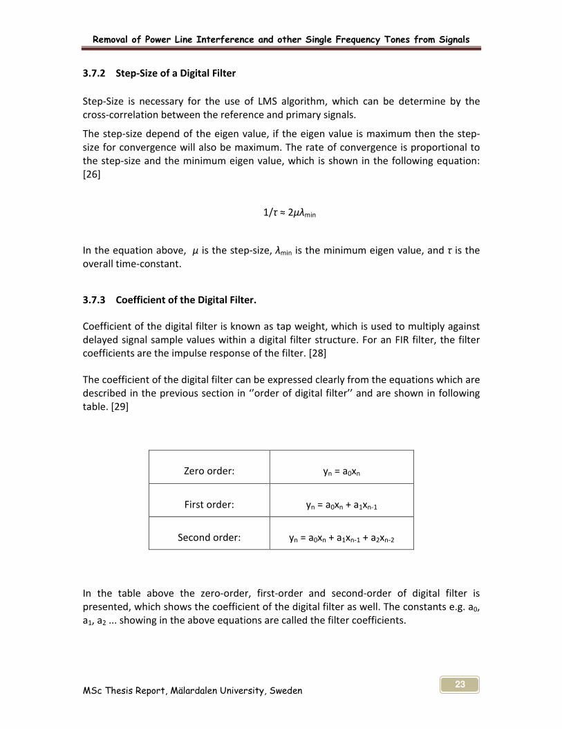
3.7.3 Coefficient of the Digital Filter.
Coefficient of the digital filter is known as tap weight, which is used to multiply against
delayed signal sample values within a digital filter structure. For an FIR filter, the filter
coefficients are the impulse response of the filter. [28]
The coefficient of the digital filter can be expressed clearly from the equations which are
described in the previous section in ‘’order of digital filter’’ and are shown in following
table. [29]
In the table above the zero-order, first-order and second-order of digital filter is
presented, which shows the coefficient of the digital filter as well. The constants e.g. a0,
a1, a2 ... showing in the above equations are called the filter coefficients.
Zero order:
yn = a0xn
First order:
yn = a0xn + a1xn-1
Second order:
yn = a0xn + a1xn-1 + a2xn-2

Removal of Power Line Interference and other Single Frequency Tones from Signals
MSc Thesis Report, Mälardalen University, Sweden 24
4 CHAPTER-4
ADAPTIVE FILTERS
4.1 Introduction
The adaptive filter can be defined as, a filter which self adjust its transfer function
according to an optimizing algorithm and object can be achieve by the modification of
its characteristics. [2] Adaptive signal processing has been introduced and its growth to
the advanced related fields of digital computing, DSP and high speed integrated circuit
technology has been made rapidly. The least mean square (LMS) adaptive filtering
algorithm’s first paper was published in 1959 by Widrow and Hoff. [30]
Adaptive filters are extensively used in the variety of application and they had been
firstly proposed by Kelly of Bell Telephone Laboratories around 1965, [20] most of the
applications are in telecommunication for the cancellation of noise and echoes in the
transmission channel and also used in digital controller for active noise control. [31]
An adaptive filter is a digital filter whose characteristics change in an unknown
environment input signal. In the advanced era of cellular phone, digital television,
wireless communication and digital multimedia commercial services, advanced adaptive
signal processing may give the better solution for the technical problem. [30] The
adaptive filter is also used in the field of biomedical, sonar, radar and image signal
processing, telecommunication for noise cancellation etc.
4.2 Explanation of Adaptive Filter
Adaptive signal processing is more famous due to the property of its digital techniques
which is characterized by flexibility and accuracy in the field of communication and
control. [32] In the advancement of digital signal processing’s application, adaptive filter
become more popular in different devices such as medical monitoring equipments,
mobiles phones and other communication devices. Most of the adaptive filters are
digital due to the complexity of optimizing algorithm, which perform digital signal
processing and adapt their performance based on the input signal. [2] When the fixed
specification of any application is unknown or can not be satisfied by time invariant
filters then an adaptive filter is required to manipulate this problem.

Removal of Power Line Interference and other Single Frequency Tones from Signals
MSc Thesis Report, Mälardalen University, Sweden 25
4.3 Adaptive Filters and Digital Signal Processing
The designing of digital filter requires the approved specification with fixed coefficients.
If this specification is time varying or not accessible then this problem can be
manipulate by digital filter with adaptive coefficients, which is know as adaptive filter.
[33] The adaptive fitters are utilized and successfully increased its application under
several regions of telecommunications and biomedical engineering i.e. interference
reduction, noise, speech and image encoding, echo cancellation, equalization of
dispersive channels, and system identification. [34]-[33]
Digital signal processing has well-known repute in the modern times, which is used for
the number of different application in different fields of technologies; biomedical
engineering is one of them where the unwanted noise from ECG can be removed by
digital filters. [34] In the modern era of communication system, adaptive signal
processing is one of the most important technologies used for numbers of different
algorithms. Generally the main problem in the biomedical systems is noise cancellation,
which is considered as adaptive noise cancellation in hi-tech and mature technology
found in the in biomedical systems, telecommunications systems, industrial control,
aerospace, and music etc. [35]
Adaptive filtering is the technique which is used to set the parameters. [33] It is one of
several tools which are made available by the digital signal processing (DSP). Usually
filters are essential part of any system which performs any kind of manipulation or
signal processing to eliminate any unwanted portion or noise induced in the signal.
So the digital filters have an appearance in the form of adaptive filtering, which provides
better performance by adjusting to changes in the noise factors.
4.4 Adaptive Filtering
Adaptive filtering is properly used due to its esteemed knowledge of signal makeup,
that’s why signal analysis is related to the adaptive processing. [32] Literally, the word
’adaptive’ means to adjust with other environment (system) by having the same
response as the system itself to some phenomenon which is taking place in it
surroundings. Or technically the system which tries to adjust its parameter, depending
upon the other system’s behavior and it’s surrounding. The systems which carries out its
functionality after undergoes the process of adaptation is called filter. The term ‘filter’
means to take the unnecessary particles (frequency component) from its input signal
and process them to generate required output under certain specific rules. [36] There
are various principal option for the implementation of adaptive signal processing, e.g.
the LMS algorithm. [31]
Removal of Power Line Interference and other Single Frequency Tones from Signals
MSc Thesis Report, Mälardalen University, Sweden 26
The adaptive filters are much famous due to their economical quality, fast processing,
their short period of time adaptation and residual error is small after adaptation. [25]
Adaptive filtering is the most important technique which is used is numbers of
biomedical applications. [4]
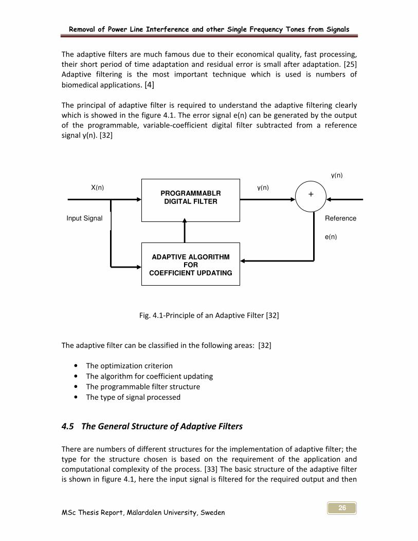
The principal of adaptive filter is required to understand the adaptive filtering clearly
which is showed in the figure 4.1. The error signal e(n) can be generated by the output
of the programmable, variable-coefficient digital filter subtracted from a reference
signal y(n). [32]
Fig. 4.1-Principle of an Adaptive Filter [32]
The adaptive filter can be classified in the following areas: [32]
• The optimization criterion
• The algorithm for coefficient updating
• The programmable filter structure
• The type of signal processed
4.5 The General Structure of Adaptive Filters
There are numbers of different structures for the implementation of adaptive filter; the
type for the structure chosen is based on the requirement of the application and
computational complexity of the process. [33] The basic structure of the adaptive filter
is shown in figure 4.1, here the input signal is filtered for the required output and then
PROGRAMMABLR DIGITAL FILTER
ADAPTIVE ALGORITHM
FOR COEFFICIENT UPDATING
+ X(n)
Input Signal
y(n)
y(n)
e(n)
Reference
Removal of Power Line Interference and other Single Frequency Tones from Signals
MSc Thesis Report, Mälardalen University, Sweden 27
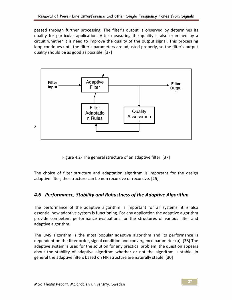
passed through further processing. The filter’s output is observed by determines its
quality for particular application. After measuring the quality it also examined by a
circuit whether it is need to improve the quality of the output signal. This processing
loop continues until the filter’s parameters are adjusted properly, so the filter’s output
quality should be as good as possible. [37]
2
Figure 4.2- The general structure of an adaptive filter. [37]
The choice of filter structure and adaptation algorithm is important for the design
adaptive filter; the structure can be non recursive or recursive. [25]
4.6 Performance, Stability and Robustness of the Adaptive Algorithm
The performance of the adaptive algorithm is important for all systems; it is also
essential how adaptive system is functioning. For any application the adaptive algorithm
provide competent performance evaluations for the structures of various filter and
adaptive algorithm.
The LMS algorithm is the most popular adaptive algorithm and its performance is
dependent on the filter order, signal condition and convergence parameter (μ). [38] The
adaptive system is used for the solution for any practical problem; the question appears
about the stability of adaptive algorithm whether or not the algorithm is stable. In
general the adaptive filters based on FIR structure are naturally stable. [30]
Adaptive Filter
Filter Adaptation Rules
Quality Assessmen
t
Filter Outpu
t
Filter Input

Removal of Power Line Interference and other Single Frequency Tones from Signals
MSc Thesis Report, Mälardalen University, Sweden 28
To satisfy the robustness of the adaptive algorithm the value of step size μ needs to be
small. [39] Robustness is an important criterion which is difficult to measure in a
quantitative approach. The satisfaction for the robustness of the adaptive algorithm can
be gained by the removal of external noise disturbances and arithmetic quantization
noise. [30]
4.7 Convergence Criteria for Adaptive Algorithm
The convergence criterion is the important performance in the adaptive algorithm
which must be according to the required or particular application. [30] For the
convergence of LMS algorithm there are different procedures. The LMS algorithm must
has the convergence condition, which is necessary for the convergence of the mean is
E [є (n)] → 0 as n→ ∞ [1]
The convergence ability of the LMS algorithm can be examined by the range of
convergence factors which provide the stability. [33] Faster convergence is better
solution for the allocation of additional resources in high frequency operation such as
mobile radio, cellular telephone, digital television (HDTV). In low frequency application
such as adaptive echo cancellation and audio band noise cancellation, the convergence
criterion is slow and this simple and adequate solution is provided by LMS algorithm.
[30]
The convergence performance of the LMS algorithm for FIR filter structure is controlled
by the autocorrelation matrix Rx.
[30]
The condition of the satisfaction can be checked and LMS algorithm’s condition must be
satisfied if the step size parameter satisfies the condition. [1] The autocorrelation matrix
Rx is necessary for the convergence. The condition which is important for the
convergence criterion and the convergence factor of LMS algorithm must be chosen in
the range is
0< μ < 1 / λ max [33]-[30]
Were λ max is the largest eigen value of the correlation matrix Rx. The speed of the LMS
algorithm’s convergence is dependent on eign value. [33] The choice of μ in the locality
of 1/ λ max is the best convergence for the adaptive algorithm. [1]-[30]
)]()(*[ nxnxERxT
=

Removal of Power Line Interference and other Single Frequency Tones from Signals
MSc Thesis Report, Mälardalen University, Sweden 29
If the matrix Rx has large eigenvalue then the vaule of μ must be much smaller than the
upper band. As a result the convergence speed of the coefficient will be primarily
dependent on the value of the smallest eigenvalue. [33]
4.8 System Identification Configuration Using an Adaptive Filter
When both the unknown system and adaptive filter are prepared by the same input
signal x(n) then adaptive filter is used in system identification configuration.[30] To
reduce the problems of system identification, adaptive filter have excellent ability to
match its output to unknown system and due to adaptive filter’s best capability for
adaptation, it is also used for the removal of interference and disturbance in the signal.
[34] In system identification configuration, the desire signal is the output of unknown
system [33] and the input signal x(n) is set for under analysis, the reference signal a(n) is
produced with input signal and the error signal e(n) is generated by the system output.
[30]-[32]
e(n) = d(n) - y(n)
Figure 4.3- System Identification Configuration for Adaptive Filter [34] -[30]-[32]
The parameters of the adaptive filters are then activated to minimize the particular
function error signal e(n). In system identification configuration when the adaptive filter
accumulated the stable values then error signal e(n) will be reduced.[30] It can be
possible for adaptive filter to converge it to a good model to match after convergence of
Unknown System H(z)
Adaptive Filter
H(z) ^
^ y(n)
a(n)
y(n)
noise, w(n)
input, x(n)
+
+
∑
+
- ,
output
error, e(n)
output d(n)
Removal of Power Line Interference and other Single Frequency Tones from Signals
MSc Thesis Report, Mälardalen University, Sweden 30
the unknown system by giving sufficient degree of freedom to the adaptive filter. [34]-
[33]
The system identification configuration is the essential adaptive filtering concept. [30]
This is used to remove the error signal while processing of any input signal with noise. It
is necessary for good performance of adaptive filter to remove the noise which is mixed
with input of the system; otherwise this noise appears at the output and can decrease
the quality of the output.
Removal of Power Line Interference and other Single Frequency Tones from Signals
MSc Thesis Report, Mälardalen University, Sweden 31
5 CHAPTER-5
ADAPTIVE ALGORITHM FOR FIR FILTERS
5.1 Introduction
The adaptive algorithm for FIR filters are is widely used in different applications such as
biomedical, communication and control due to its easily implementation, stability and
best performance. Its simplicity makes it attractive for many applications where it is
need to minimize computational requirements.
5.2 Advantages of Filters and Adaptive Algorithm
Today’s medical monitoring equipments and other devices facing variety of interfering
signals which are usually corrupted by noise and other interferences. The power line
interference (50/60 Hz) in ECG signal is the major problem in the field of biomedical
(medical monitoring equipments) and field of communication (cell phone and
communication devices). So filters play an important role for removal of unwanted
signal or noise from original input signal by removing the selected frequencies from
incoming signal. They became much popular due to the increase of the digital signal
processing.
The designing of the adaptive filter, it’s rational to choose the adaptive algorithm and
LMS algorithm can be selected for this designing purpose, which is core contributing
factor for the success of algorithm functioning. [30] Filters are used in biomedical
instruments, as the frequency of biomedical instruments are very low so digital filters
are much popular for low frequency applications. [17]
For any application of the adaptive filters, the input signal and the reference input
required being process; the least mean square is used to adjust the weight of the
adaptive filter in order to minimize the error. The best solution to remove the unwanted
signal or noise from the input signal, the reference noise must be filter out by using
adaptive filtering method due to its good performance and reliability.

Removal of Power Line Interference and other Single Frequency Tones from Signals
MSc Thesis Report, Mälardalen University, Sweden 32
5.3 Finite Impulse Response (FIR)
A finite Impulse Response (FIR) filter are type of digital filters [40] and consists of
weighting sequence (impulse response) among non-recursive digital filters which is
finite in length. [41] FIR filters are non recursive digital filters [40] has been selected for
this thesis due to their good characteristics and can be used to implement in any sort of
frequency response digitally. The series of multipliers, delays and adders are used for
FIR filters’ implementation for filter’s output. The output of the non recursive digital
filter is formed from the weighted linear combination of current input and previous
value of the input. [19]
Figure 5.1- Finite impulse response (FIR) filter structure [42]
The filter structure of FIR is presented in the figure 5.2, which described the relationship
between input and output sequences which also described the basic structure and
diagram of FIR filter having a length of N (where N is filter order) and the input samples
are operated by the delays of results. All the delayed samples are multiplied by suitable
coefficient as the hk is the coefficient value for multiplication for output at time n. [42]
The selection of FIR filter is due to coefficient sensitivity, round off noise, stability and
suitable for high speed applications. [13]
FIR and IIR filters are two different classes of digital filters, these digitals filters can be
implemented for different application. The selection of any type of digital filter is based
on the practical implementation of required application. The FIR filter is mostly applied
for adaptive filtering and the main choice of FIR filter was its stability and robustness.
∑ +
+ + +
X X X X
7 -1
7 -1
7 -1
7 -1
y(n) ^
a n a 2 a 1 a 0
Removal of Power Line Interference and other Single Frequency Tones from Signals
MSc Thesis Report, Mälardalen University, Sweden 33
5.4 FIR Filters Advantages and Disadvantages
The FIR filter has linear phase characteristics and its operation in for the finite history of
data. FIR is used to manipulate the corrupted data and it operates with less period of
time. Following are the advantages and disadvantages of FIR filters. [24]
5.4.1 Advantages:
� FIR Filter are Linear Phase
� Coefficients are easy and simple to calculate
� The design methods are generally linear
� Complex filters with many band of different gains
� FIR filters are always Stable
� They can be realized efficiently in hardware
5.4.2 Disadvantages:
� Lower Selectivity than IIR filters
� High filter order required for "sharp" frequency edges
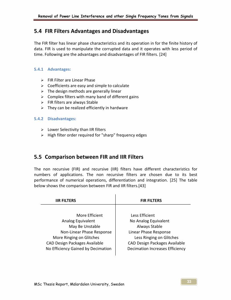
5.5 Comparison between FIR and IIR Filters
The non recursive (FIR) and recursive (IIR) filters have different characteristics for
numbers of applications. The non recursive filters are chosen due to its best
performance of numerical operations, differentiation and integration. [25] The table
below shows the comparison between FIR and IIR filters.[43]
IIR FILTERS FIR FILTERS
More Efficient Less Efficient
Analog Equivalent No Analog Equivalent
May Be Unstable Always Stable
Non-Linear Phase Response Linear Phase Response
More Ringing on Glitches Less Ringing on Glitches
CAD Design Packages Available CAD Design Packages Available
No Efficiency Gained by Decimation Decimation Increases Efficiency

Removal of Power Line Interference and other Single Frequency Tones from Signals
MSc Thesis Report, Mälardalen University, Sweden 34
Comparison between the different characteristics of FIR and IIR can be made in variety
of ways. The most important benefit of FIR filters over IIR filters is the flexibility in
preferred frequency retort. The FIR filter might be ideal when hardware minimization
and delay minimization are important. [43] Its easy to design the non recursive filters as
compared to recursive filters. [25] Most of the applications for adaptive FIR and IIR
filtering include noise and echo cancellation and the FIR and IIR structures can be used
as adaptive filters and Stability problems. FIR filters are used for all practical
applications. [44] Reliability which is always an important issue regardless of the nature
of the design, is also an advantage offered by the FIR filters over IIR filters.
5.6 Adaptive FIR Signal Processor
There are specific functions for any signal processor to complete its tasks. For this
purpose there must be some type of algorithm to control the process to give correct and
required output for the system. Adaptive FIR signal processor is one of the famous
algorithms to manipulate and minimize the signal error.
In the figure 5.3 adaptive signal processor’s model function is shown, the input signal
x(k) is taken and the output y(k) is showed with the error signal e(k). The adaptive FIR
algorithm is used to manipulate or minimization of the power of the error signal e(k),
this algorithm is called adaptive signal processing algorithms. The error signal must be
minimized by adapting the signal x(k), such that the filter output y(k) is very similar to
some desired signal d(k). [35]
Figure 5.2- The Adaptive Signal Processor [35]
Removal of Power Line Interference and other Single Frequency Tones from Signals
MSc Thesis Report, Mälardalen University, Sweden 35
This Adaptive FIR signal processing model can be used for different applications which
are as follow,
(a) Noise cancellation
(b) System identification
(c) Inverse system identification
(d) Prediction

Removal of Power Line Interference and other Single Frequency Tones from Signals
MSc Thesis Report, Mälardalen University, Sweden 36
6 CHAPTER-6
LEAST MEAN SQUARE (LMS) ALGORITHM
6.1 Adaptive Filter Algorithms
There are many types of algorithms which had been developed to use in adaptive digital
filters i.e. LMS (Least Mean Square), RLS (Recursive Least Square, NLMS (Normalized
Least Mean Square), etc. The best algorithm to utilize in the removal of power line
interference, most commercial applications favors the LMS. This is mainly because it is
easy to implement and exhibits stability in performance.
6.2 Introduction to LMS Algorithm
The LMS algorithm is extensively used in different application of adaptive filtering due to
low computational complexity, stability and unbiased convergence. [33] In any signal’s
processes there can be error occurred in the required output. There must be suitable
algorithm needed to manipulate this problem. The least mean square (LMS) algorithm is
introduced to minimize the error between a given preferred signal and output of the
linear filter by adjusting recursively the parameters of a linear filter. [45] The more
suitable and basic algorithm for the adaptive filtering is LMS, which is also famous for
the stability of the system. [46] LMS is the most important algorithms in whole family of
algorithms, which has been developed for minimizing the error. [45] This algorithm is
used for the better condition of input signal to attain the faster convergence [33] and
can address a range of problem settings, computational restrictions and minimization
criteria. [45]
Every application needs its simple and easy solution, the LMS algorithm has been
selected for this thesis due to its simplicity, robustness and ease of implementation.
Simplicity and robustness are its major future and it is the widely used in adaptive
filtering algorithm for different applications. [47] The different areas where LMS
algorithm is used include adaptive signal processing, system identification and adaptive
control. [46] Due to its simplicity and robustness, it has made the standard for the
adaptive filtering and is much famous for the different application as compared to other
linear adaptive algorithms. [48]
Least mean square algorithm has lots of benefits in different applications; it has been
productively used in many applications due to the following performance aspects. [45]

Removal of Power Line Interference and other Single Frequency Tones from Signals
MSc Thesis Report, Mälardalen University, Sweden 37
� LMS have the ability to reject noisy data due to minute step size parameter μ.
� LMS demonstrate slowly time varying system.
� LMS algorithm does not get stuck at undesired local minima.
� LMS is computationally simple memory competent.
In general LMS adaptive filter removes noise or obtains a desired signal by adapting the
filter coefficient with least-square algorithm based on given filter. [49] The performance
of the LMS algorithm is very high and it is simple in implementation for the removal of
low frequency noise. The suitable value for step size parameter μ can be selected
according to the application’s requirement.
6.3 Overview of the Structure and Operation of the LMS Algorithm
LMS is used for the simplification of gradient vector computation. [33] The overview of
the structure and operation of the LMS algorithm can be discussed according to LMS
algorithm’s properties and its processes. [48] The main property of LMS algorithm is its
convergence behavior in a stationary environment. [33] LMS is a linear adaptive filtering
algorithm and is consists of two basic processes.
� Filtering Process
Filtering process is used to calculate the output of linear filter and to generate an
estimated error by comparing this output with a desire response. [48]
� An Adaptive Process
An adaptive process is used for the automatic adjustment of the filter’s parameters in
accordance with the estimated error. [48]
Figure 6.1- LMS Adaptive Algorithm [50]
LMS adaptive filter L,µ,∆,α
Z -∆
Primary input d + e
y
Reference input
∑
x
-

Removal of Power Line Interference and other Single Frequency Tones from Signals
MSc Thesis Report, Mälardalen University, Sweden 38
In the figure 6.1, the overview of least mean square (LMS) algorithm is shown. The
primary input has been taken, where ‘X’ is the reference input. The error signal occurs
for the desired output, there LMS adaptive filter has employed to manipulate the error.
The error signal manipulated by the adaptive algorithm is describe as
e(n) = d(n) - y(n) [50]
The equation above shows the desired signal and the filter output, where d(n) is the
desired signal and y(n) is the filter output. For the minimization of error signal the input
vector x(n) and e(n) are employed. Here it needs to work according to the criterion that
is supposed to minimize. The input vector is used to update the adaptive coefficients
according to that criterion. The criterion used here is the mean-square error (MSE) e:
e = E[e2(n)] [50]
6.4 Design of an Adaptive Filter Algorithm
The adaptive filters are self designing filters, which determine the updating of filter
coefficients requires the extra information in the form of signal. This signal is called
desired or reference signal. [33]
The signal processing system for adaptive filters processes different signal in different
algorithm grounded in statistical basis. [51] The adaptive filters are used for those
applications where it needs to operate for high speed, it is essential to minimize the
hardware complexity. [33] Due to simple mathematics of the LMS algorithm, it focuses
on its transversal filter structure: the input data vector which is stored in the delay
elements of the filter is computed as a linear combination with its output. [51]
The Adaptive algorithm tries to minimize an appropriate objective or error function that
involves the input, reference and filter output signal. This algorithm can be consist of
three parts, the definition of minimizing algorithm, the definition of objective function
and the definition of error signal. [52] The LMS algorithm is much attractive for different
application due to its simplicity and accessible analysis under idealized conditions. [33]

Removal of Power Line Interference and other Single Frequency Tones from Signals
MSc Thesis Report, Mälardalen University, Sweden 39
Figure 6.2- Outline of adaptive transversal filter [51]
The outline of adaptive signal processing system is describes in figure 6.2. The input to
the adaptive filter is described as scalar real-valued discrete-time signal x(n) where n is
the time index. At time n, the samples x(n), x(n - 1), . . . through x(n -N + 1) are
simultaneously present in the delay elements of the filter.
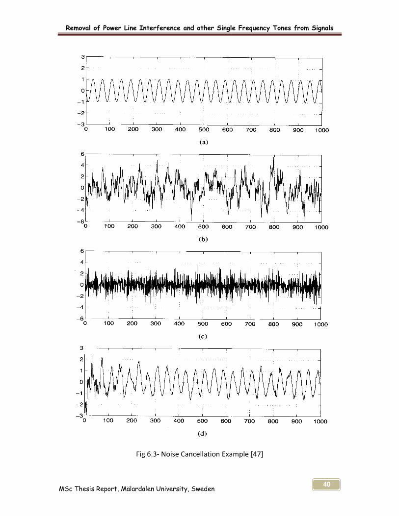
6.5 Noise Cancellation
The noise cancellation is severe problem in signals, the process d(n) in noise cancellation
is estimated from a noise corrupted observation.
x(n) = d (n) + v1 (n)
There must be some information about d(n) or v1 (n) for the separation of signal from
noise. The reference signal may be used to estimate the noise v1 (n), and this estimate
may then be subtracted from x(n) to form an estimate of d(n). [47]
Transversal Filter
Adaptation Algorithm
+
y(n|n-1)
c(n-1)
d(n)
+ x(n)
e(n)
Removal of Power Line Interference and other Single Frequency Tones from Signals
MSc Thesis Report, Mälardalen University, Sweden 40
Fig 6.3- Noise Cancellation Example [47]

Removal of Power Line Interference and other Single Frequency Tones from Signals
MSc Thesis Report, Mälardalen University, Sweden 41
The Fig 6.3 describe the complete process of noise cancellation step by step
(a) Represent the information signal,
(b) Represent the noise signal,
(c) Represent the mixed signal of information and noise signals,
(d) Represent the original signal after filtration.
The principle of noise cancellation is to obtain noise signal and subtract it from the
corrupted signal. The required signal can be found after subtracting the corrupted signal
from noise. [36] The figure above represents the information signal (a) and the noise
signal (b), both the signals are mixed together and then mixed signal (c) is displayed. To
remove the noise signal (b) from information signal (a) there must be some filtration
method which is based on the application requirement. The original signal (d)
represents the output signal after filtration.
6.6 Adaptive Noise Cancellation
Adaptive noise cancellation can be consideration as an outgrowth of the interference
cancellation. One of the adaptive noise cancellation applications was to remove 50/60
Hz noise from ECG signal. [53]
Figure 6.4- Block Diagram of Adaptive Noise Canceller [30]-[31]-[47]-[48]
Adaptive Filter
Signal Source
Noise Source
d(n) Primary
Input e(n)
x(n)
Reference Input
y(n)
+
Filter Output
Error Signal
s + no
n1
z
System Output
Removal of Power Line Interference and other Single Frequency Tones from Signals
MSc Thesis Report, Mälardalen University, Sweden 42
At the primary input signal ‘s’ is measured together with noise is assumed to be the sum
of an information signal and sinusoidal interference. For monitoring of the noise ‘n1’ a
reference input supplies a correlated version of the sinusoidal interference. The
correlation of the noises ‘no’ and ‘n1’ is assumed to be high and have same origin so that
influence of the useful signal ‘s’ is negligible at the reference input. [31] The filter uses
the reference input to provide an estimate of sinusoidal interfering signal contained in
the primary input. The adaptive filter forms as estimate of ‘no’ thus by subtracting the
adaptive filter output from the primary input signal. So the information signal with noise
is cancelled at the output by adaptive noise cancellation method. [30]
There are two important characteristics of LMS algorithm i.e. canceller behaves as an
adaptive notch filter, which is tunable and the notch in the frequency response can be
made very sharp by choosing the small value of the step size parameter μ. [48] The
noise cancellation is required to remove unnecessary noise from the given signal. The
term cancellation principle is used to detect the noise and subtract that noise from the
corrupted signal. Its feasibility depends upon the availability of a noise signal originating
signal. The concept of noise cancellation in its simplest form is described in figure 6.3.
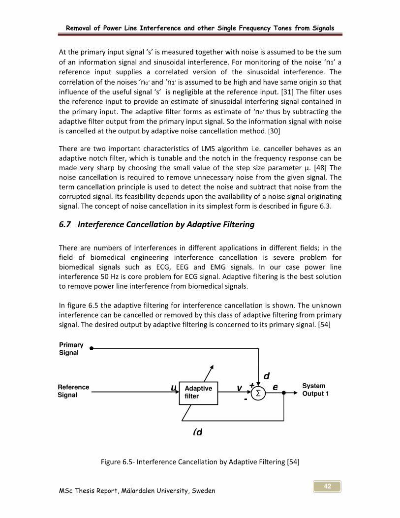
6.7 Interference Cancellation by Adaptive Filtering
There are numbers of interferences in different applications in different fields; in the
field of biomedical engineering interference cancellation is severe problem for
biomedical signals such as ECG, EEG and EMG signals. In our case power line
interference 50 Hz is core problem for ECG signal. Adaptive filtering is the best solution
to remove power line interference from biomedical signals.
In figure 6.5 the adaptive filtering for interference cancellation is shown. The unknown
interference can be cancelled or removed by this class of adaptive filtering from primary
signal. The desired output by adaptive filtering is concerned to its primary signal. [54]
Figure 6.5- Interference Cancellation by Adaptive Filtering [54]
Adaptive filter
System Output 1
Reference Signal
Primary Signal
u y +d
e
-∑
(d

Removal of Power Line Interference and other Single Frequency Tones from Signals
MSc Thesis Report, Mälardalen University, Sweden 43
According to above adaptive interference cancellation method the reference signal is
employed as an input to the adaptive filter. The sensor (s) which supplying the primary
signal can derive a reference signal in such a manner that the information bearing signal
becomes essentially undetectable or weak. [54]

Removal of Power Line Interference and other Single Frequency Tones from Signals
MSc Thesis Report, Mälardalen University, Sweden 44
7 CHAPTER-7
DESIGN, ANALYSIS AND SIMULATIONS
7.1 Main Objective
The goal was to implement and analyze of different noise removal techniques in ECG
signal. Removal of power line interference 50/60 Hz from ECG signal and how to apply
the adaptive LMS algorithm for removing of power line interference and its harmonic
from signals that has been corrupted and the original information contained by
unwanted interferences was main purpose of the thesis. The additional milestone of the
project was to investigation and implementation for the removal of harmonics and high
frequency noise from ECG signal in MATLAB environment.
Numbers of algorithms can be implemented in ECG signal to remove the different type
of noises. In this thesis, two different types for removal of noises have been
implemented.
– Removal of Power Line Interference by Adaptive LMS Algorithm from
original ECG Signal.
– Removal of harmonics and high frequency noise by general notch
rejection filter from original ECG signal.
While the thesis problem and purpose was not as simple to solve and implement as it
might, the possible benefits were enormous. The challenges for the project were the
study of most sensitive biomedical monitoring equipments such as Electrocardiogram
(ECG), electroencephalogram (EEG) and electromyography (EMG). The thesis is basically
research oriented; therefore sufficient reference materials were not available easily. The
results, analysis, implementation and conclusion of the thesis are totally depends upon
better understanding of ECG signal’s simulation and calculation. It was totally out of
domain so a lot of journals, research papers, internet, university library database and
books are read to analyze and understand it in a better way.

Removal of Power Line Interference and other Single Frequency Tones from Signals
MSc Thesis Report, Mälardalen University, Sweden 45
7.2 Design by DSP Technique
In digital signal processing (DSP) it is mainly encounter with discrete time signals which
are functions of integers. The signals are also represented by mathematical function like
sinusoidal function or linear difference equations.
In this thesis it deals with two signals i.e. input ECG signal (50 Hz) and noise signal (50
Hz) from power line source. In the case of removal of noise by adaptive LMS algorithm,
this was implemented because of easy to implement and exhibits stability in
performance.
The ECG signal of 50 Hz is taken and mixed with noise signal of 50 Hz; if nothing is
known about noise signal then it can not be subtracted from ECG signal. But in this case
the noise signal of 50 Hz is eliminated by using adaptive LMS algorithm which estimates
the noise related to input noise and subtracts it from input signal to generate the
estimated signal’s output. The LMS algorithm changes the filter coefficients and working
system subtracts it from the actual system’s outputs.
The frequencies among 47 Hz and 53 Hz are more critical for ECG signal of 50 Hz. These
frequencies can be noise for the ECG signal and due to it the quality of ECG recording
can be get down. So nothing seems to be best to use adaptive filter which overcome the
information loss in the ECG recording. For a good DSP system it must fulfils many
requirements, i.e. it must responds to all input frequencies, should be stable, more
reliable for the manipulation of signals.
The most important objective for the choice of adaptive filters was its ability to adjust
the filter’s coefficients and the main designating factor was how to define rules or
algorithms that upgrade coefficients. The adaptive filters judge the performance from
signal and it also tract the signal, develop the solution and determine how filter
coefficients should be upgraded.
7.3 MATLAB Software Implementation
MATLAB is the most useful environment for engineering and technology
implementations software package. It is used for the specific purpose in different fields
of technology based on electronic programming, scientific & engineering graphical
illustration, accurate numerical calculation and algorithms development etc. The
algorithm has been designed and implemented the least mean square (LMS) adaptive
filter based upon the FIR filtering using MATLAB environment. The adaptive filtering is
selected with the objective of removing 50/60 Hz noise from ECG signal. The code is
written for input signal which is supposed to be ECG signal of frequency 50 Hz and the
second signal of noise (frequency1=50 Hz) which is power line interference of 50 Hz has

Removal of Power Line Interference and other Single Frequency Tones from Signals
MSc Thesis Report, Mälardalen University, Sweden 46
generated. The FIR adaptive filter has then implemented there and LMS algorithm has
been developed to filter out the low frequency noise from ECG signal. The simulation
results with graphs for ECG signal were then plotted to compare the filtered output by
putting different values of LMS step size and filter tap to visually measure the simulation
program performance. Finally the algorithm implementation and verification has been
presented which increases the reason for the selection of LMS algorithm based on FIR
filters in MATLAB environment. The affects of μ on convergence rate and stability for
the LMS adaptive filter has been examined to achieve the desire results.
The simulation of harmonics of high frequency noise has also been generated to find out
another filtration method in MATLAB environment. The general notch rejection filter
and windowed sinc low pass filter has been developed in MATLAB for the
implementation and removal of harmonics & high frequency noise to achieve the
required output.
7.4 Verification for Refinement of Signal by LMS
The verification for refinement of signal by LSM can be done with the removal of power
line interference (50 Hz) from ECG signal.
7.4.1 Removal of Power Line Interference (50 Hz) from ECG Signal by LMS Algorithm
The ECG signal has been taken and LMS adaptive filter algorithm has been developed.
The ECG signal of 50 Hz is displayed in MATLAB environment as ECG Signal and than the
noise of 50 Hz is generated and then mixed with the ECG Signal, which is displayed as
Mixed signal. The adaptive filter is implemented by using LMS algorithm, FIR filter has
been designed. The ECG Signal, 50 Hz Noise signal, Mixed signal, Error signal and
Adaptive LMS filtered output signal have been displayed. The output is nearly same as
the ECG inputted signal.

Removal of Power Line Interference and other Single Frequency Tones from Signals
MSc Thesis Report, Mälardalen University, Sweden 47
7.4.1.1 Simulation for Power Line Interference and its Removal from ECG Signal
FilterTap=16;
mu = 0.005;
0 1000 2000 3000 4000 5000 6000 7000 8000 9000 10000-1
0
1Original ECG Signal
0 1000 2000 3000 4000 5000 6000 7000 8000 9000 10000-1
0
150 Hz Noise Signal
0 1000 2000 3000 4000 5000 6000 7000 8000 9000 10000-2
0
2Mixed Signal
0 1000 2000 3000 4000 5000 6000 7000 8000 9000 10000-5
0
5Error Signal
0 1000 2000 3000 4000 5000 6000 7000 8000 9000 10000-2
0
2LMS Filtered Output
ECG Signal Simulation-1

Removal of Power Line Interference and other Single Frequency Tones from Signals
MSc Thesis Report, Mälardalen University, Sweden 48
FilterTap=16;
mu = 0.009;
0 1000 2000 3000 4000 5000 6000 7000 8000 9000 10000-1
0
1Original ECG Signal
0 1000 2000 3000 4000 5000 6000 7000 8000 9000 10000-1
0
150 Hz Noise Signal
0 1000 2000 3000 4000 5000 6000 7000 8000 9000 10000-2
0
2Mixed Signal
0 1000 2000 3000 4000 5000 6000 7000 8000 9000 10000-5
0
5Error Signal
0 1000 2000 3000 4000 5000 6000 7000 8000 9000 10000-2
0
2LMS Filtered Output
ECG Signal Simulation-2
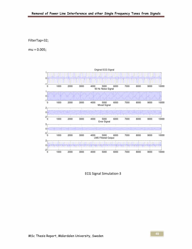
Removal of Power Line Interference and other Single Frequency Tones from Signals
MSc Thesis Report, Mälardalen University, Sweden 49
FilterTap=32;
mu = 0.005;
0 1000 2000 3000 4000 5000 6000 7000 8000 9000 10000-1
0
1Original ECG Signal
0 1000 2000 3000 4000 5000 6000 7000 8000 9000 10000-1
0
150 Hz Noise Signal
0 1000 2000 3000 4000 5000 6000 7000 8000 9000 10000-2
0
2Mixed Signal
0 1000 2000 3000 4000 5000 6000 7000 8000 9000 10000-5
0
5Error Signal
0 1000 2000 3000 4000 5000 6000 7000 8000 9000 10000-2
0
2LMS Filtered Output
ECG Signal Simulation-3
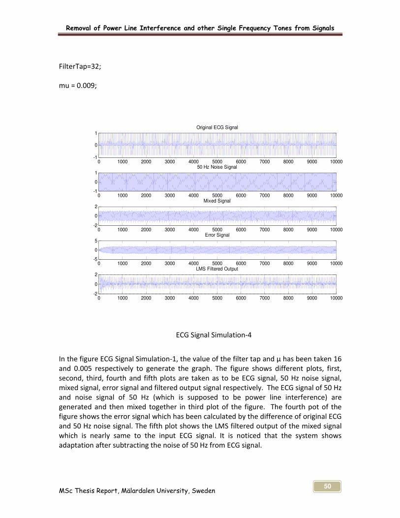
Removal of Power Line Interference and other Single Frequency Tones from Signals
MSc Thesis Report, Mälardalen University, Sweden 50
FilterTap=32;
mu = 0.009;
0 1000 2000 3000 4000 5000 6000 7000 8000 9000 10000-1
0
1Original ECG Signal
0 1000 2000 3000 4000 5000 6000 7000 8000 9000 10000-1
0
150 Hz Noise Signal
0 1000 2000 3000 4000 5000 6000 7000 8000 9000 10000-2
0
2Mixed Signal
0 1000 2000 3000 4000 5000 6000 7000 8000 9000 10000-5
0
5Error Signal
0 1000 2000 3000 4000 5000 6000 7000 8000 9000 10000-2
0
2LMS Filtered Output
ECG Signal Simulation-4
In the figure ECG Signal Simulation-1, the value of the filter tap and µ has been taken 16
and 0.005 respectively to generate the graph. The figure shows different plots, first,
second, third, fourth and fifth plots are taken as to be ECG signal, 50 Hz noise signal,
mixed signal, error signal and filtered output signal respectively. The ECG signal of 50 Hz
and noise signal of 50 Hz (which is supposed to be power line interference) are
generated and then mixed together in third plot of the figure. The fourth pot of the
figure shows the error signal which has been calculated by the difference of original ECG
and 50 Hz noise signal. The fifth plot shows the LMS filtered output of the mixed signal
which is nearly same to the input ECG signal. It is noticed that the system shows
adaptation after subtracting the noise of 50 Hz from ECG signal.
Removal of Power Line Interference and other Single Frequency Tones from Signals
MSc Thesis Report, Mälardalen University, Sweden 51
In the second figure ECG Signal Simulation-2, the value of filter tap and µ are taken as 16
and 0.009, which shows different results as compared to the ECG Signal Simulation-1. It
is concluded that the rate of convergence is changed by changing the value of µ.
In the figure ECG Signal Simulation-3, the value of filter tab has been changed from 16 to
32 and µ is taken as 0.005. This shows the ECG signal (50 Hz) and noise signals (50 Hz)
are mixed together and the filtered out by using LMS adaptive filter. This figure can be
compare with the ECG Signal Simulation-4 where the value of filter tab and µ are taken
as 32 and 0.009 respectively. In this simulation graph the value of µ is decreased which
shows the small change in the coefficient and the convergence of filter act as slowly. So
it is concluded that with large step-size the filter convergence takes place fast. It is also
concluded that with the large value of µ, the filter convergence act as fast. By changing
the results and convergence rates, finally it is concluded that the LMS adaptation take
place properly and it performed adaptation.
7.4.2 Removing of Harmonics and High Frequency Noise from Original ECG Signal
To the verification of removal of noise from original ECG signal, another method has
been developed for the implementation and analysis of different noise removal
technique in ECG signal. The test for the simulation of ECG signal has been taken by
adding different noises.
Humming which is also known as low frequency noise has been taken and added in the
original ECG signal. The major work is concerned with removing undesired frequency
harmonics while saving the original information in the signal as much as possible during
this elimination process.
Biomedical signals play an important role for monitoring of patient’s ECG. High
frequency noise can also be added with ECG signal while diagnosis of patient in hospital
or some where else. This high frequency noise can be added due to the use of Mobile
phone near patient or some other sources.
The original ECG signal with noises is passed through notch and windowed sinc low pass
filter, which filter out hum and high frequency noise portion from the ECG signal. With
this process the unwanted noise signal can be removed from ECG signal, and then
original ECG signal without noise can be obtained.
The graph of original ECG signal with hum (low frequency noise) and high frequency
noise is displayed in figure below. In the first plot of the figure the original ECG signal
has displayed and the hum and high frequency noise are displayed in second and third
plots respectively. Then both noises humming and high frequency noise has been added
to the original ECG signal, which is shown in the fourth plot as mixed signal.

Removal of Power Line Interference and other Single Frequency Tones from Signals
MSc Thesis Report, Mälardalen University, Sweden 52
Notch rejection filter is employed for the removal of humming (50 Hz). As there are two
different noises in this case i.e. humming and high frequency noise, both noises after
passing through the notch filter, the signal with high frequency noise remain with the
original ECG signal in the fifth plot of the figure.
Finally the corrupted signal is passed through windowed sinc low pass filter to retrieve
the original ECG signal. The high frequency noise is then filtered out by using windowed
sinc low pass filter and the desire output of the ECG signal has then achieved at the final
output. By comparing the graph of input original ECG signal with the output, it is
concluded that the overall result of method and technique developed in this thesis is
achieved. The goal for the noise cancellation or removal of different noise frequencies
has been performed satisfactory.
7.4.2.1 Simulation for Harmonics and High Frequency Noise and its Removal from
Original ECG Signal
0 200 400 600 800 1000 1200-1
0
1
EC
G
0 200 400 600 800 1000 1200-1
0
1
HU
M
0 200 400 600 800 1000 1200-20
0
20
HF
-No
ise
0 200 400 600 800 1000 1200-20
0
20
Mix
ed
Sig
0 200 400 600 800 1000 1200-20
0
20
Wit
ho
ut
Hu
m
0 200 400 600 800 1000 1200-2
0
2
Ou
tpu
t
Original ECG Signal with HUM and High Frequency Noise Simulation by Notch Filter

Removal of Power Line Interference and other Single Frequency Tones from Signals
MSc Thesis Report, Mälardalen University, Sweden 53
After analysing the filtering technique for humming and high frequency noise from ECG
signal, it is concluded that implementation and analysis has been performed more or
less the same and it also shows the method and filtering technique developed for the
removal of harmonics and high frequency noise from ECG signal performed its operation
and meet the required results.
7.5 Algorithm Implementation and Verification
Biomedical signals play a critical role in the diagnosis of patients. ECG is a medical
monitoring device which is used for the diagnosis of heart patient. As power line
interference 50/60 Hz is major problem in ECG signal. An algorithm for the LMS adaptive
filter was suggested, as the ECG signal can be variously mixed with power line
interference of 50 Hz. The LMS adaptive filter is widely used to filter the ECG signal as its
convergence causes good performance. To verify the performance of the LMS adaptive
algorithm, ECG signal has been selected and evaluated the performance of the proposed
filtering technique.
The MATLAB environment was used for the simulation of ECG signal. The code contents
of the source file used in this thesis were collected from various sources. For the
completion of code, the collected contents were modified according to the application’s
requirement and placed in the required sequence. To design the FIR filter, these source
files were used to configure the DSP technique. After designing of FIR filter the LMS
algorithm has been executed and verified.
Two basic processes are involved when the LMS algorithm is applied, a filter process
involving the computation of the output of FIR filter produced by a vector of tap inputs
and an estimation error signal calculated by comparing this output to a desired
response.
LMS algorithm is extensively used in different application of adaptive filtering due to its
computational simplicity and FIR filter is also popular because of its simplicity and
inherent stability. An important parameter is the step size μ, it affects the convergence
rate and stability of the LMS adaptive filter. If μ is small, it will create a slower rate of
convergence but is more accurate and stable. On the other hand, if it is large, it will
converge faster but will become less accurate and less stable.
Moreover another method has been implemented for the removing of harmonics
(known as low frequency noise) and high frequency noise from original ECG signal. The
humming and high frequency noise has been removed by using general notch rejection
filters and windowed sinc low pass filter. The original ECG signal (50 Hz) has been taken
and mixed with the hum and then both the ECG and Hum signals are added with high
Removal of Power Line Interference and other Single Frequency Tones from Signals
MSc Thesis Report, Mälardalen University, Sweden 54
frequency noise of 375 Hz. After passing the ECG signal with both noises through notch
filter, the ECG signal with high frequency noise remains. Then this remaining signal with
high frequency noise has been passed through the windowed sinc low pass filter to get
rid of high frequency noise. By use this method the original ECG signal can be retrieved.
By investigating this method, it is concluded that the overall result of the technique is
achieved. The main goal for the removal of different noise i.e. harmonics and a high
frequency noise has been performed satisfactory.
Removal of Power Line Interference and other Single Frequency Tones from Signals
MSc Thesis Report, Mälardalen University, Sweden 55
8 CHAPTER-8
8.1 CONCLUSION AND FUTURE RESEARCH
8.1.1 Conclusion
This report is devoted to the problems and solutions on removal of Power Line
Interference and other Single Frequency Tones from Signals. The understanding of noise
cancellation from ECG signal was explained clearly to the readers, the methods and
techniques applicable to be used discussed through out the report. It has been
proposed a solution for the power line interference its respective harmonics and high
frequency noise interferences from original ECG signal. The results have been obtained
which were required in purpose statement of the report.
In general FIR filters are used because these types of filters have simple architecture and
are logically stable, so the FIR filter was chosen for the development of the system. The
research has been made for the selection of filters and algorithm, two kind of adaptive
filters i.e. FIR (Finite impulse response) & IIR (Infinite impulse response) and two kinds
of algorithms, the LMS (least mean square) & RLS (recursive least squares) algorithms
were studied and examined. The LMS algorithm is the most widely used adaptive
filtering algorithm in biomedical monitoring equipments, so it was decided to be
employed for the thesis to get the required solution for the main purpose. The
applications of the LMS algorithm can be implemented due to its simplicity and
robustness.
An adaptive filter is used in applications that require different filter characteristics in
response to variable signal conditions. The speed of adaptation and accuracy of the
noise cancellation after adaptation are important measures of performance for noise
cancellation algorithm. The goal of the adaptive filter is to match the filter coefficients
to the noise so that the adaptive filter can subtract the noise out from signal. So
adaptive filtering technique was selected to achieve the goal of thesis.
The test for the simulation of ECG signal has been taken. The signal is corrupted by
power line interference of 50 Hz. It is observed that the frequency of the power line
interference is 50 Hz which is then mixed with original ECG signal, it is also examined
that the mixed signal is displayed on the plot. After passing through LMS algorithm the
filtered output is nearly same as the input signal with some acceptable distortion range.
The value of step size μ play an important role in determining the convergence speed,
stability and residual error after convergence. The convergence rate was controlled by
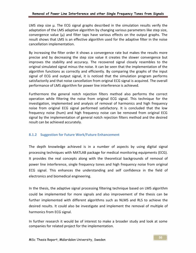
Removal of Power Line Interference and other Single Frequency Tones from Signals
MSc Thesis Report, Mälardalen University, Sweden 56
LMS step size μ. The ECG signal graphs described in the simulation results verify the
adaptation of the LMS adaptive algorithm by changing various parameters like step size,
convergence value (µ) and filter taps have various effects on the output graphs. The
result shows that LMS is an effective algorithm used for the adaptive filter in the noise
cancellation implementation.
By increasing the filter order it shows a convergence rate but makes the results more
precise and by decreasing the step size value it creates the slower convergence but
improves the stability and accuracy. The recovered signal closely resembles to the
original simulated signal minus the noise. It can be seen that the implementation of the
algorithm functions as correctly and efficiently. By comparing the graphs of the input
signal of ECG and output signal, it is noticed that the simulation program performs
satisfactorily and that noise cancellation from original ECG signal is acquired. The overall
performance of LMS algorithm for power line interference is achieved.
Furthermore the general notch rejection filters method also performs the correct
operation while filtering the noise from original ECG signal. This technique for the
investigation, implemented and analysis of removal of harmonics and high frequency
noise from original ECG signal performed satisfactory. It is concluded that the low
frequency noise (hum) and high frequency noise can be removed from original ECG
signal by the implementation of general notch rejection filters method and the desired
result can be achieved accurately.
8.1.2 Suggestion for Future Work/Future Enhancement
The depth knowledge achieved is in a number of aspects by using digital signal
processing techniques with MATLAB package for medical monitoring equipments (ECG).
It provides the real concepts along with the theoretical backgrounds of removal of
power line interference, single frequency tones and high frequency noise from original
ECG signal. This enhances the understanding and self confidence in the field of
electronics and biomedical engineering.
In the thesis, the adaptive signal processing filtering technique based on LMS algorithm
could be implemented for more signals and also improvement of the thesis can be
further implemented with different algorithms such as NLMS and RLS to achieve the
desired results. It could also be investigate and implement the removal of multiple of
harmonics from ECG signal.
In further research it would be of interest to make a broader study and look at some
companies for related project for the implementation.

Removal of Power Line Interference and other Single Frequency Tones from Signals
MSc Thesis Report, Mälardalen University, Sweden 57
9 APPENDIX A
9.1 MATLAB CODE FOR ECG SIGNAL
% Removal of Power Line Interference from ECG Signal
% 50 Hz Noise removal from ECG signal by the implementation of LMS algorithm
clear;
clc
close all;
fullscreen = get(0,'ScreenSize');
figure('Position',[ fullscreen(3)/4 fullscreen(4)/4 fullscreen(3)/1.5 fullscreen(4)/1.5])
% Create the signal
% Original ECG signal
Fs = 1000;
Length=1000*10;
i=1:Length;
ECG_signal=ecg(50);
ECG=ECG_signal;
for i=1:Length/50-1
ECG_signal=[ ECG_signal ECG];
clc
end

Removal of Power Line Interference and other Single Frequency Tones from Signals
MSc Thesis Report, Mälardalen University, Sweden 58
frequency1=50; % Frequency of Noise Signal
% Range of the ECG Signal
i=1:length(ECG_signal);
Noise_signal = sin(2*pi*frequency1*i/Fs); % Power Line Interference
% Range of the Noise Signal embedded in the ECG
Mixed_signal = ECG_signal + Noise_signal; % ECG Signal Plus Noise
%%%%%%%%%%%%%%%% POWER LINE INTERFERENCE %%%%%%%%%%%%%%%
%%%%%%%%%%%%%Adaptive filtering using LMS algorithm%%%%%%%%%%%%%
%Power line Hum=noise;
x=ECG_signal;
n=Noise_signal;
m=Mixed_signal;
d=x+n+m;
n1=rand()*Noise_signal;
length_filter=15;
w=ones(1,length_filter);
mu=0.005; % Lest Mean Square (LMS) step size.
FilterTap=16;
for i=1:Length
y1=0;
if i<length_filter
for j=1:i
y1=y1 + w(i,j)*n1(i-j+1);
end
else
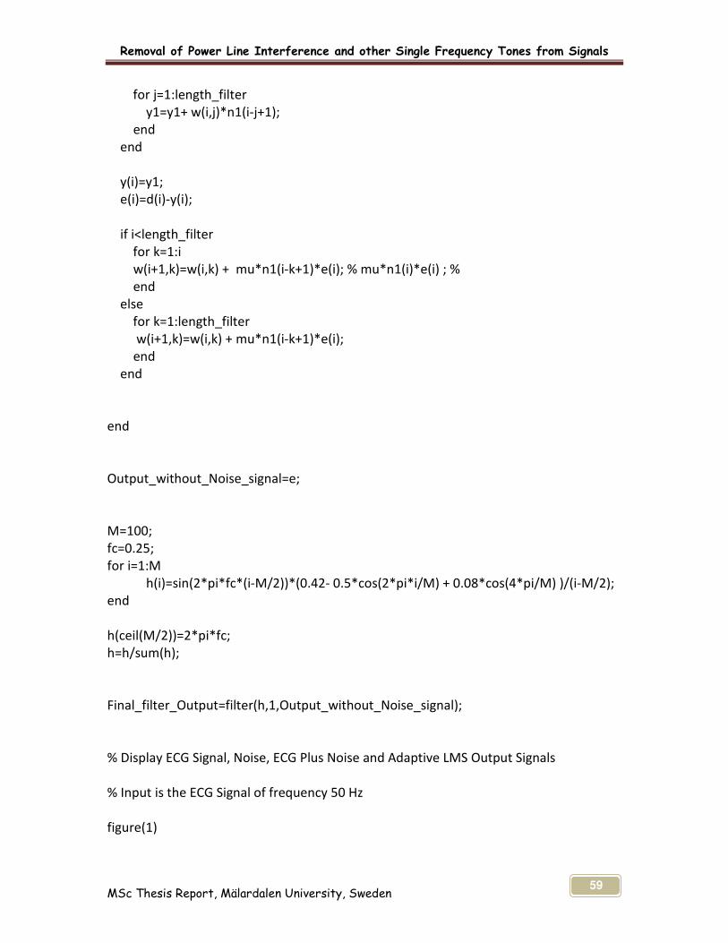
Removal of Power Line Interference and other Single Frequency Tones from Signals
MSc Thesis Report, Mälardalen University, Sweden 59
for j=1:length_filter
y1=y1+ w(i,j)*n1(i-j+1);
end
end
y(i)=y1;
e(i)=d(i)-y(i);
if i<length_filter
for k=1:i
w(i+1,k)=w(i,k) + mu*n1(i-k+1)*e(i); % mu*n1(i)*e(i) ; %
end
else
for k=1:length_filter
w(i+1,k)=w(i,k) + mu*n1(i-k+1)*e(i);
end
end
end
Output_without_Noise_signal=e;
M=100;
fc=0.25;
for i=1:M
h(i)=sin(2*pi*fc*(i-M/2))*(0.42- 0.5*cos(2*pi*i/M) + 0.08*cos(4*pi/M) )/(i-M/2);
end
h(ceil(M/2))=2*pi*fc;
h=h/sum(h);
Final_filter_Output=filter(h,1,Output_without_Noise_signal);
% Display ECG Signal, Noise, ECG Plus Noise and Adaptive LMS Output Signals
% Input is the ECG Signal of frequency 50 Hz
figure(1)

Removal of Power Line Interference and other Single Frequency Tones from Signals
MSc Thesis Report, Mälardalen University, Sweden 60
% Original ECG Signal
subplot(5,1,1); plot(x) ;title('Original ECG Signal');
% Power Line Interference (Low Frequency Noise)
subplot(5,1,2);plot(n) ;title('50 Hz Noise Signal');
% Mixed ECG Signal with Power Line Interference (50 Hz)
subplot(5,1,3);plot(m) ;title('Mixed Signal');
subplot(5,1,4);plot(d-e) ;title('Error Signal');
% Filtered Output
subplot(5,1,5);plot(Final_filter_Output) ;title('LMS Filtered Output');
grid on;
hold on;
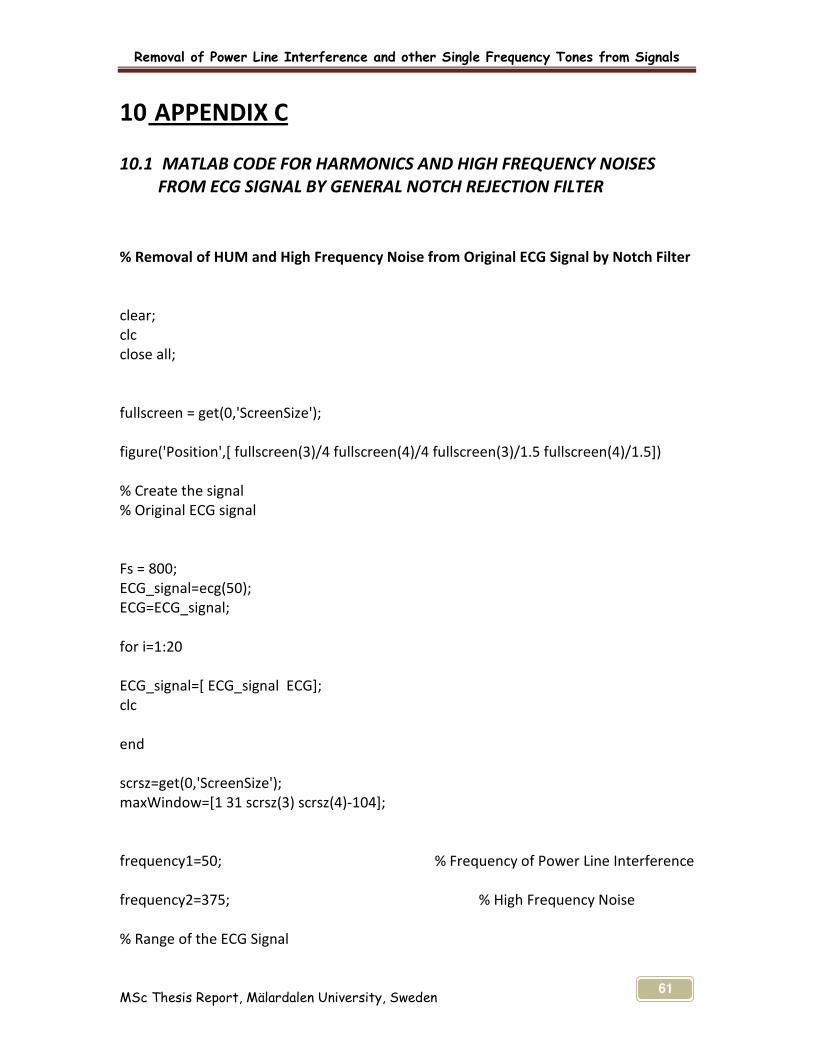
Removal of Power Line Interference and other Single Frequency Tones from Signals
MSc Thesis Report, Mälardalen University, Sweden 61
10 APPENDIX C
10.1 MATLAB CODE FOR HARMONICS AND HIGH FREQUENCY NOISES
FROM ECG SIGNAL BY GENERAL NOTCH REJECTION FILTER
% Removal of HUM and High Frequency Noise from Original ECG Signal by Notch Filter
clear;
clc
close all;
fullscreen = get(0,'ScreenSize');
figure('Position',[ fullscreen(3)/4 fullscreen(4)/4 fullscreen(3)/1.5 fullscreen(4)/1.5])
% Create the signal
% Original ECG signal
Fs = 800;
ECG_signal=ecg(50);
ECG=ECG_signal;
for i=1:20
ECG_signal=[ ECG_signal ECG];
clc
end
scrsz=get(0,'ScreenSize');
maxWindow=[1 31 scrsz(3) scrsz(4)-104];
frequency1=50; % Frequency of Power Line Interference
frequency2=375; % High Frequency Noise
% Range of the ECG Signal

Removal of Power Line Interference and other Single Frequency Tones from Signals
MSc Thesis Report, Mälardalen University, Sweden 62
i=1:length(ECG_signal);
HUM = sin(2*pi*frequency1*i/Fs); % Low Frequency HUM Signal
% Range of the Noise Signal Embedded in the ECG
High_Frequency_Noise = 5*sin(2*pi*frequency2*i/Fs + pi/4) +
10*cos(2*pi*(frequency2+50)*i/Fs + 2*pi/7 ) ; % High Frequency Noise Signal
Mixed_Signal = ECG_signal + High_Frequency_Noise + HUM; % ECG Signal Plus Noise
Fn = Fs/2; % Nyquist Frequency [Hz]
W0 = 50; % Notch Frequency [Hz]
w0 = W0*pi/Fn; % Notch frequency Normalized
BandWidth = 10; % -3dB BandWidth [Hz]
B = BandWidth*pi/Fn; % Normalized Bandwidth
k1 = -cos(w0); k2 = (1 - tan(B/2))/(1 + tan(B/2));
b = [1+k2 2*k1*(1+k2) 1+k2];
a = [2 2*k1*(1+k2) 2*k2];
Output_without_Hum=filter(b,a,Mixed_Signal);
M=100;
fc=0.25;
for i=1:M
h(i)=sin(2*pi*fc*(i-M/2))*(0.42- 0.5*cos(2*pi*i/M) + 0.08*cos(4*pi/M) )/(i-M/2);
end
h(ceil(M/2))=2*pi*fc;
h=h/sum(h);
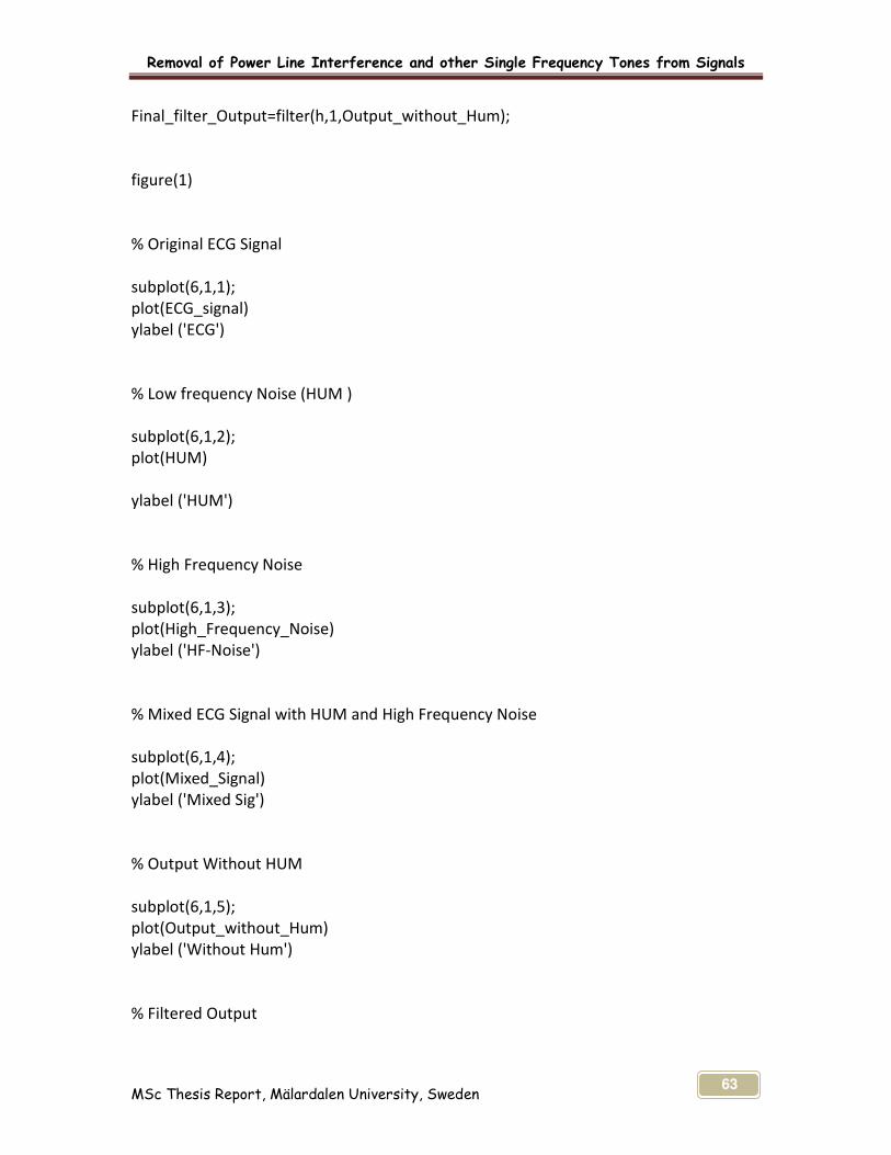
Removal of Power Line Interference and other Single Frequency Tones from Signals
MSc Thesis Report, Mälardalen University, Sweden 63
Final_filter_Output=filter(h,1,Output_without_Hum);
figure(1)
% Original ECG Signal
subplot(6,1,1);
plot(ECG_signal)
ylabel ('ECG')
% Low frequency Noise (HUM )
subplot(6,1,2);
plot(HUM)
ylabel ('HUM')
% High Frequency Noise
subplot(6,1,3);
plot(High_Frequency_Noise)
ylabel ('HF-Noise')
% Mixed ECG Signal with HUM and High Frequency Noise
subplot(6,1,4);
plot(Mixed_Signal)
ylabel ('Mixed Sig')
% Output Without HUM
subplot(6,1,5);
plot(Output_without_Hum)
ylabel ('Without Hum')
% Filtered Output

Removal of Power Line Interference and other Single Frequency Tones from Signals
MSc Thesis Report, Mälardalen University, Sweden 64
subplot(6,1,6);
plot(Final_filter_Output)
ylabel ('Output')
%grid on;
hold on;

Removal of Power Line Interference and other Single Frequency Tones from Signals
MSc Thesis Report, Mälardalen University, Sweden 65
11 REFERENCES
The list of information gathered from books, journals and internet sites.
[1] Stacy Finlay, Carrie Klekta and Ernie Packulak, Adaptive Noise Cancellation for
ECG Signal, 2002
[2] http://en.wikipedia.org/wiki/Adaptive_filter Accessed on 2008-11-22
[3] Rolf Limacher, Removal of power line interference from the ECG signal by an
Adaptive digital filter, ETH Zurich, laboratory of Electrical Engineering Design
Gloriast, Zurich
[4] Applications of Adaptive Filtering to ECG Analysis, Noise Cancellation and Arrhythmia
Detection Nitish V . Thakor, Seiiior Member, IEEE, and Yi-Sheng Zhu, Se~iior Momher,
IEEE
[5] http://www.eng.nus.edu.sg/EResnews/0410/sf/sf_7.html Accessed on 2008-11-23
[6] http://www2.netdoctor.co.uk/health_advice/examinations/ecg.htm Accessed on
2008-09-13
[7] http://www.essortment.com/all/howhumanheart_roua.htm Accessed on 2008-11-23
[8] http://www4.ncsu.edu/~xzhang11/PDF/525_proj1.pdf
[9] Dr. A. Michael Noll, Technological Challenges of Power Line, Feb 5 (2002)
California, Telecommunication, Annenberg School of Communication at the
University of Southern Los Angeles. and Baseline Drift Removal, Depart of Psychology,
Second University of Naples,Italy and International Institute for Advanced Scientific
Studies, Italy. Block Approach Harvey Mudd College, California.
[10] Anna Esposito, Pierluigi D. Andria, An Adaptive Learning Algorithm for ECG Noise
[11] John Leis, Digital Signal Processing- A MATLAB-Based Tutorial Approach, Research
Studies Press Ltd. 2002
[12] http://www.mathworks.com Accessed on 2008-11-21
[13] Hakan Johansson, Synthesis and Realization of High-Speed Recursive Digital Filters,
University of Linkoping, Sweden, 1998
[14] MATLAB Software help
[15] Philip D. Cha , John I. Molinder , Fundamentals of Signals and Systems, A Building
[16] John G. Proakis, Dimitris G. Manolakis Digital Signal Processing, Principles,
Algorithm and Applications
[17] Emmanuel. C. Ifeachor, Barrie. W. Jervis, Digital Signal Processing
[18] Rahman Jamal, Mike Cerna, John Hanks Designing Filters Using the Digital Filter
Design Toolkit
[19] Edward P. Cunningham, Digital Filtering An Introduction, John Wiley & Sons, Inc.
1995
[20] Haykin S, Adaptive Filter Theory, 2nd Edition, United Stated of American: Prentice-
Hall, Inc. 1991,
[21] Krister Landernas, Implementation of Digital Filters Using Digital-Series
Arithmetics, Department of electronics, Licentiate thesis No. 23, 2004

Removal of Power Line Interference and other Single Frequency Tones from Signals
MSc Thesis Report, Mälardalen University, Sweden 66
[22] http://www.dsptutor.freeuk.com/dfilt2.htm Accessed on 2008-11-22
[23] http://www.intersil.com/data/AN/an9603.pdf Accessed on 2008-11-21
[24] Nicholas John Loy, An Engineer’s Guide to FIR Digital Filters, Prentice Hall, 1988
[25] Andreas Antoniou, Digital Filters Analysis, Design and Applications, Second Edition,
McGraw-Hill, Inc. 1993
[26] B. Widow, "Adaptive noise cancelling: principles and applications", Proceedings of
the IEEE, vol. 63,
[27] http://www.dsptutor.freeuk.com/dfilt5.htm Accessed on 2008-11-23
[28] http://www.dspguru.com/info/terms/filtterm/index2.htm Accessed on 2008-11-22
[29] http://www.dsptutor.freeuk.com/dfilt6.htm Accessed on 2008-11-23
[30] W. Kenneth Jenkins, Andrew W. Hull, Jeffrey C. Strait, Bernard A. Schnaufer, Xiaohui
Li, Advanced Concept in Adaptive Signal Processing, Kluwer Academic Publisher 1996
[31] Per Sjosten, Adaptive Noise Control Using The LMS Algorithm, Chalmer University
of Technology
[32] Maurice G. Bellanger, Adaptive Digital Filters, Second Edition Revised and
expended, Marcel Dekker, Inc. 2001
[33] Paulo S.R. Diniz, Adaptive Filtering Algorithm and Practical Implementation,
Kluwer Academic Publishers, 1997
[34] Michael S. White and Stuart J. Flockton, Adaptive Recursive Filtering using
Evolutionary Algorithms. Department of Physics, Royal Holloway, University of
London.
[35] B. Widrow and S. Stearns. Samuel D. Adaptive Signal Processing. Prentice Hall,
Inc,1985
[36] Farhang Boroujeny, B. Adaptive Filters: Theory and Applications. Chichester: John
Wiley and Sons, 1998
[37] Treichler, John. R. and Johnson Jr., Richard C. and Larimore, Michael G. Theory
and Design of Adaptive Filters. New York: John Wiley and Sons, 1987
[38] Yuu-Seng Lau, Zahir M. Hussian and Richard Harris, Performance of Adaptive
Filtering Algorithms: A Comparative Study, Centre for Advanced Technology in
Telecommunications (CATT), School of Electrical and Computer Engineering RMIT
University, Melbourne, Victoria, Australia.
[39] Ali H. Sayed, Fundamentals of Adaptive Filtering, John Wiley & Sons Inc, 2003
[40] Cedric Keip, Design of a Finite Impulse Response Filter Coefficients Computation
Tool Using Evolutionary Strategies and Extension to Filter Bank Design, 2004
[41] Terrell, Trevor J. Introduction to Digital Filters. Second Edition, London:
Macmillan, 1980
[42] C.F.N. Cowan, P.M Grant, Adaptive Filters, United States of America: Prentice
Hall, Inc. 1985
[43] Thomas J. Cavicchi, John, Digital Signal Processing, Wiley & Sons, Inc 2000
[44] http://dualist.stanford.edu/~ee265/www-Sept2006/docs/digital_filters.pdf
Accessed on 2008-11-22
[45] N. Kalouptsidis. Adaptive System Identification and Signal Processing Algorithm
(University of Athens) and S. Theodoridis (University of Patras) Prentice Hall
Inc.,1993.

Removal of Power Line Interference and other Single Frequency Tones from Signals
MSc Thesis Report, Mälardalen University, Sweden 67
[46] L. Guo, L. Ljung, G.J. Wang, Necessary and Sufficient Condition for Stability of LMS,
Department of Electrical Engineering, Linkoping University, Sweden, 1995
[47] Monson H. Hayes, Jonson. Statistical Digital Signal Processing and Modeling,
Wiley & Sons.
[48] Simon Haykin, Adaptive Filter Theory, Fourth Edition, Prentice Hall, Inc 2002
[49] International Journal of Control, Automation, and Systems, vol. 3, no. 1, March
2005
[50] Charles Le and Scott Hensley. RFI removal from AIRSAR polarimetric data, Jet
Propulsion Laboratory California Institute of Technology
[51] Special issue on Adaptive Signal Processing of the International Journal computers
& Electrical Engineering Vol. 18, No. 3/4, 1992.
[52] A. Zaknich, Principles of Adaptive Filters and Self-Learning Systems, Springer
[53] John L. Semmlow, Robert Brunswick, Biosignal and Biomedical Image Processing
Matlab-Based Applications, New Hersey, U.S.A. Rutgers University, Piscataway,
New Jersey, U.S.A.
[54] Haykin, S. Adaptive Filter Theory. Third Edition. New Jersey: Prentice-Hall,
Inc.1996