renew pmi theme pfc panel report - ucla … · renew pmi theme pfc panel report panel team members...
TRANSCRIPT

ReNeW PMI Theme PFC Panel Report
Panel team members :C. Wong ( GA), B. Lipschultz (MIT), T. Leonard (GA), R. Majeski (PPPL), D. Youchison (SNL), B. Merrill (INL)R. Doerner (UCSD), S. Milora (ORNL)
US Department of Energy
OFES Research Needs Workshop (ReNeW)
University of California, Los Angeles
March 2–6, 2009
• Organization
• First question at the beginning: What are we doing?
• Technologists to physicists: What heat fluxes will the DEMO have?
• Physicists to technologists: What are your design limits?
• Both sides agreed: We have significant challenges ahead.
• The team then worked on requirements and issues of different areas.
• Generated the PFC Matrix showing issues and needs for different areas.
• We do have a draft PFC related research thrusts

PFC is a Tier 1 priorityGreenwald Priority Tier 1: solution not in hand, major extrapolation from current
state of knowledge, need for qualitative improvements and substantial development
for both short and long term
• Plasma Facing Components
• Materials
Plasma Facing Components: Understand the materials and processes that
can be used to design replaceable components that can survive the enormous
heat, plasma and neutron fluxes without degrading the performance of the
plasma or compromising the fuel cycle.

ReNeW PMI PFC Organization
Panel member focused areas:• Physics (Lipschultz and Leonard)• Solid surface and design (Wong)• Liquid metal and design (Majeski)• Surface heat transfer and components
testing and analysis (Youchison)• Tritium, safety and RAMI (Merrill)• Surface materials (Doerner)• Maintenance and development program (Milora)
Review…requirements…development… thrusts… …for the next 15-20 years
ITER design asan initial example
To project robust PFC design and development we created the ~ 1000 MWe DEMO key PFC parameters:Mid-plane Γn-max =3 MW/m2
FW φ-max= 0.5-4.0 MW/m2 (TBD)Div φ-max = 10 MW/m2 (steady state)
+ 20 MW/m2(10-100s) (pulses TBD)

EU Roadmap Divertor Development towards ITER & DEMO
[P. Norajitra et al.]

constant load
for DEMO
*
**
For DEMO:
ELMs have to be supressed,
VDEs and disruption
„unlikely events“
(Vertical Displacement Events)
(Edge Localized Modes)
Intro (6): Assumptions for DEMO Design from EU
* Number of events in ITER
[T. Ihli, Summer School 2007, Karlsruhe,
Germany]

Intro (5): Example Divertor Cassette for Model C from EU
Replacement
scheme
[P. Norajitra et al.]

1-Finger module
10 MW/m2
Divertor cassette
Dome and structure
(ODS RAFM)
Outboard
Inboard
Divertor target plates
with modular thermal
shield (W/W alloy)
9-Finger module
Reference Design:
He-cooled modular divertor with jet cooling (HEMJ)
(DBTT, irr.)
1300°C
700°C
600°C
300°C
600°C inl.
700°C outl.
(RCT, irr.)
WL10
Thimble
creep rup.strength
(DBTT, irr.)
He coolant
ODS Euro
Structure
Temperature
windows
18
} 5
[T. Ihli]

HEMJ-J1c
• W-tile: Non-castellated, russ. W• WL10 thimble• W/W joint: STEMET 1311• W-Steel joint by Cu castingHe data:• 10 MPa• 13.5 g/s (∆P 0.31 MPa*)• Tin = 520-570°C• Tout = 550-600°CResults:• 10 cycles each at 4,6,10,11
MW/m2 ok• Failure in W/W joint after 6 cycles
at ~13 MW/m2• He Loop and thimble still intact
W-tile
Detached area
W-thimble
Steel ring
Conical Cu-
cast lock
*) about 0.085 MPa equivalent
at 6.8 g/s nominal
EF
RE
MO
V u
nd
er
FZ
K c
on
tra
ct
Overall results:
No suddenly
and/or completely
broken mock-up,
i.e. no brittle
failure.
Nor was a
recrystallisation of
the thimble
observed in any
mock-up.
2006 HHF test results (mockup #4)
Crack in thimble, growing from inside

Test conditions:
• 10 MW/m2
• 30s / 30s sharp power ramp
THe,in 550°C, 10 MPa, mfr 7 g/s
• Tile temperature rise after 89 cycles*
--> tile probably partially detached.
• He Loop and thimble still intact.
• Post examination underway
Current Distribution of the Heat Flux used in Efremov
0
2
4
6
8
10
12
0 10 20 30 40 50 60 70
time in [s]
heat
flu
x i
n [
MW
/m^
2]
heat flux
2007: HHF test of optimized HEMJ mockup
*n required ~ 100 - 1000 Post-examined
at FZJ [T. Hirai,
G. Ritz]
2007 overall
results:
successful HHF
tests of optimized
HEMJ mockup 10
MW/m2
(survived 100
thermal cycles,
30s-30s sharp
ramp, w/o
damages)
Castellation: cracks parallel to heat flux, W defect

Wall loads on plasma facing components in ITER
Thermal load during ELMS: 1 GWm-2, t = 500 µs, 1 Hz high cycle thermal fatigue
critical area
flat tile design
W
monoblock
CFC
M. Roedig
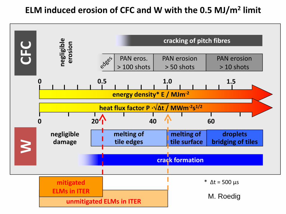
ELM induced erosion of CFC and W with the 0.5 MJ/m2 limit
CFC
W
energy density* E / MJm-2
0.5 1.0 1.50
heat flux factor P ·Δt / MWm-2s1/2
20 400 60
melting of tile surface
dropletsbridging of tiles
melting oftile edges
crack formation
cracking of pitch fibres
PAN eros.> 100 shots
PAN erosion> 50 shots
PAN erosion> 10 shotsn
egl
igib
lee
rosi
on
negligibledamage
unmitigated ELMs in ITER
mitigated ELMs in ITER
* Δt = 500 µs
M. Roedig

PFC team went through a detailed identification of PFC requirements and issues
Seven PFC panel areas: 1. Physics, 2. Solid surface and design, 3. Liquid metal and design4. Surface heat transfer and components testing and analysis 5. Tritium, safety and RAMI, 6. surface materials, 7. maintenance and development program

ReNeW PMI PFC Solid surface & design: Wong
Requirements:
• Configure surfaces to reduce peak heat flux, material erosion and deposition• Components life time: FW 4years (TBD), divetor 2 years (TBD)• Disruption and transient events tolerance (TBD) even for unlikely events• Robust components to withstand all Demo operating scenarios, including all
operational & transient E&M loads and structural and thermal stresses (including effects from neutron irradiation, cyclic fatigue, thermal creep, fracture toughness, fracture mechanics effects), while providing a design margin of 1.3 (TBD)*
• Adjust to major divertor configuration change if recommended?• Divertor design to maximize flexibility, surface can be shifted back and forth by ± 5°
when required by operation. • Design with removable chamber first wall (TBD)?• Assess the renewable low-Z surface on W option?• Design with high thermal efficiency• Develop predictive capability via modeling and analysis
(Not covered or provided in the Greenwald report)
Review…requirements…development… thrusts …for the next 20 years

ReNeW PMI PFC Solid surface & design: Wong
Review…requirements…development… thrusts…for the next 20 years
Development needs:
•Demo design: Use a projected Demo design to define the pre-conceptual design with
gradual increase of details: including physics, configuration, segmentation, routing,
maintenance, structural support…etc.
• Industrial connection: Establish connections with industry on PFC components design,
fabrication and testing of different scale of PFC components
• Modeling: If necessary develop PFC relevant design codes, coupled with dedicated
analysis codes and commercial design codes
• Fusion materials design codes
• Connections: Continue to work with physicists, first wall material designers, heat transfer
and components developers and testing professionals
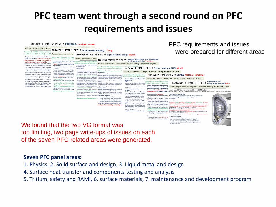
PFC team went through a second round on PFC requirements and issues
PFC requirements and issues
were prepared for different areas
We found that the two VG format was
too limiting, two page write-ups of issues on each
of the seven PFC related areas were generated.
Seven PFC panel areas: 1. Physics, 2. Solid surface and design, 3. Liquid metal and design4. Surface heat transfer and components testing and analysis 5. Tritium, safety and RAMI, 6. surface materials, 7. maintenance and development program


PFC MatrixPFC Gaps: To Develop Understanding for the Construction of Robust PFC Components
Thoeory &
Modeling
Existing/Upgrade/
New Test stands
Existing Upgraded
Confinement
facilities
New Confinemet
Facility
Chamber & Div. heat flux
Steady state
Transient
Example 1
Solid surface design
Liquid surface design Example 2
Tritium in solid,
mix materials
Example 3
Maintenance
Innovations Example 4
• Possible temperature range: RAF/M-350 to 550 C, ODFS Tmax-700-800 C, W-alloy 700-1300 C
• Design guidelines: FW heat flux ~0.5 MW/m2, Max. heat flux ~10 MW/m2,
ELMs with rise time of 125-250 µs, energy flux ~0.5 MJ/m2
• Inputs to be developed jointly with PWI and other panels
• Inputs to be developed jointly with other panels

PFC Matrix Example 1 (physics)PFC Gaps: To Develop Understanding for the Construction of Robust PFC Components
(Physics) Theory & ModelingDefine chamber spatial and temporal heat loads
1st principles modelingChamber & Divertor heat flux
ConventionalExtended channel(s) (e.g. SXD, snowflakes)
Divertor physics, integrated with PMI effects,1st principles modeling
Transients:
Startup/shutdown Define start/up & shutdown parameters
Model suppression and elimination of high
ELMs power ELMs
Disruption Model disruption avoidance and mitigation,
Other off normal events: eliminate off normal events
MARFE, Improve neutral and photon modeling
H-L transition Model avoidance of MARF, H-L transition heat load
Heat dumps Define occasional ELMs and heat dump locations and parameters by 1st principles modeling
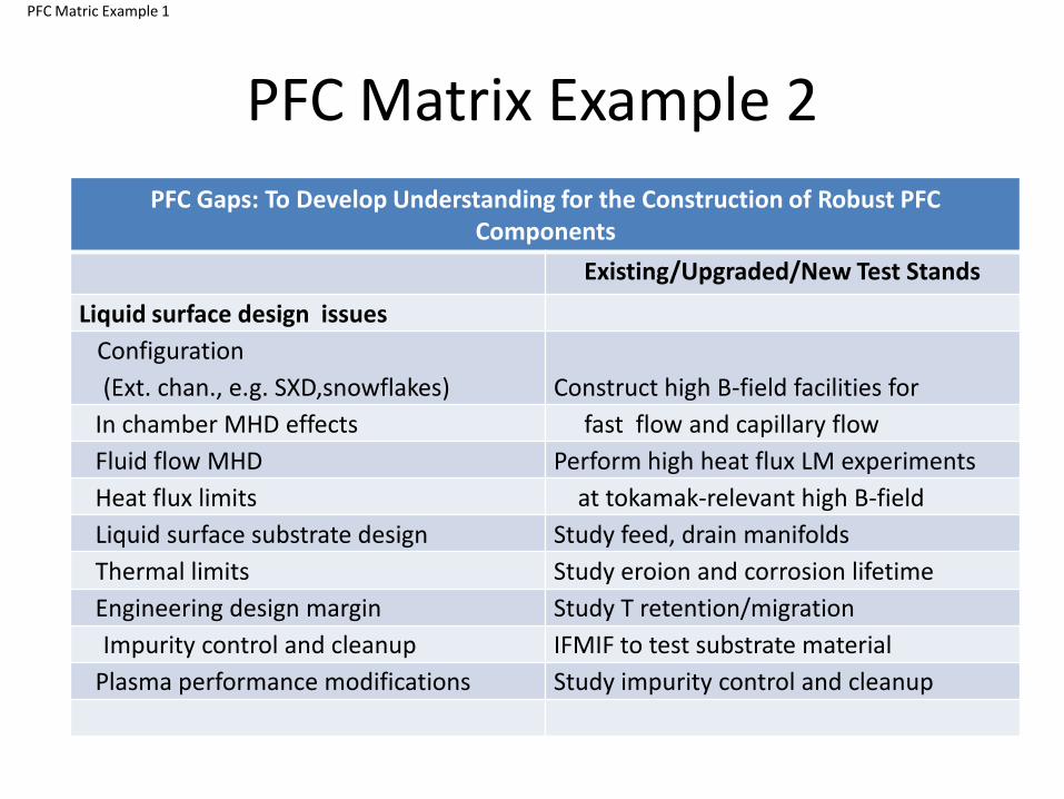
PFC Matrix Example 2
PFC Matric Example 1
PFC Gaps: To Develop Understanding for the Construction of Robust PFC Components
Existing/Upgraded/New Test Stands
Liquid surface design issues
Configuration
(Ext. chan., e.g. SXD,snowflakes) Construct high B-field facilities for
In chamber MHD effects fast flow and capillary flow
Fluid flow MHD Perform high heat flux LM experiments
Heat flux limits at tokamak-relevant high B-field
Liquid surface substrate design Study feed, drain manifolds
Thermal limits Study eroion and corrosion lifetime
Engineering design margin Study T retention/migration
Impurity control and cleanup IFMIF to test substrate material
Plasma performance modifications Study impurity control and cleanup

PFC Matrix Example 3
PFC Gaps: To Develop Understanding for the Construction of Robust PFC Components
Existing/Upgraded Confinement Facilities
Tritium in solid, mix materials
Tritium permeation/migration Validate understanding of tritium
transport and inventory on PFC materials
Materials/irradiation Experiments with innovative and
irradiated PFC materials
Safety limits Testing of tritium diagnostics
Accountancy Develop and test permeation barriers
Test interface joining materials, initiate
material qualification
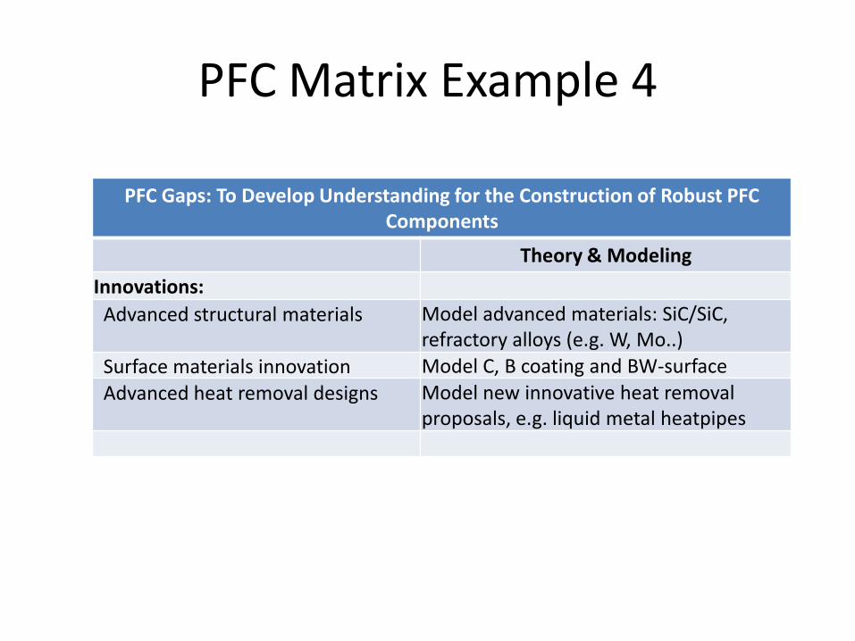
PFC Matrix Example 4
PFC Gaps: To Develop Understanding for the Construction of Robust PFC Components
Theory & Modeling
Innovations:
Advanced structural materials Model advanced materials: SiC/SiC, refractory alloys (e.g. W, Mo..)
Surface materials innovation Model C, B coating and BW-surface
Advanced heat removal designs Model new innovative heat removal proposals, e.g. liquid metal heatpipes
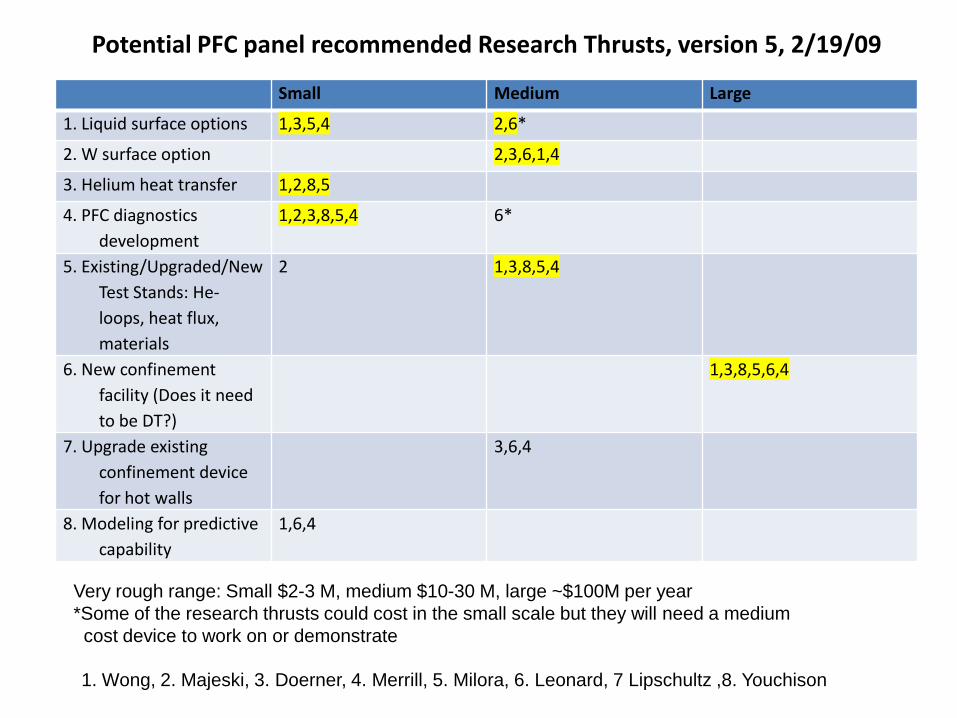
Potential PFC panel recommended Research Thrusts, version 5, 2/19/09
Small Medium Large
1. Liquid surface options 1,3,5,4 2,6*
2. W surface option 2,3,6,1,4
3. Helium heat transfer 1,2,8,5
4. PFC diagnostics
development
1,2,3,8,5,4 6*
5. Existing/Upgraded/New
Test Stands: He-
loops, heat flux,
materials
2 1,3,8,5,4
6. New confinement
facility (Does it need
to be DT?)
1,3,8,5,6,4
7. Upgrade existing
confinement device
for hot walls
3,6,4
8. Modeling for predictive
capability
1,6,4
Very rough range: Small $2-3 M, medium $10-30 M, large ~$100M per year
*Some of the research thrusts could cost in the small scale but they will need a medium
cost device to work on or demonstrate
1. Wong, 2. Majeski, 3. Doerner, 4. Merrill, 5. Milora, 6. Leonard, 7 Lipschultz ,8. Youchison
Conclusions• We have identified that with presently available materials for ITER water cooled PFC
components are already pushed to the edge of acceptable performance
• When extended to DEMO with RAFM steel as structural material and He as the coolant, disruptions will have to be avoided and ELMs will have to be mitigated or eliminated. Generation of robust PFC design will be a significant challenge, and could be by itself a major Research Thrust.
• Requirements and issues for physics, solid and liquid surface design, heat transfer and components testing and analysis, tritium, safety and RAMI, PFC surface material, maintenance, RAMI and development program areas have been identified.
• Innovative approaches on structural material, PFC material and heat removal will be needed
• A PFC matrix and a first collection of research thrust have been generated.
• We will continue to assess research thrust as a tool to meet our goal of have robust DEMO PFC components.
PFC remains a Greenwald Priority Tier 1 area: solution not in hand,
major extrapolation from current state of knowledge, need for qualitative
improvements and substantial development for both short and long term