renoldflex couplings - renold plc - manufacturer of chain ... · small waste conveyor-belt s small...
TRANSCRIPT

www.renold.com
Renoldflex Couplings

www.renold.com
Superior Gear & Coupling Technology
InterchangeabilityMany of the products fromRenold Gears are dimensionallyinterchangeable with othermanufacturers gear units,allowing a trouble freereplacement of gearboxes,in most cases upgrading thecapacity through state of theart technology and materials.
Custom MadeRenold Gears is unique in it’sability to offer custom madeproducts designed to meetcustomers exactingrequirements withoutcompromise on availability andcost. From complete packagesolutions to individual precisionreplacement gears, all can betailor made to meet specificapplicational requirements.
AvailableThe most popular ranges ofgearboxes are available fromlocal distribution stock, backedup by extensive stocks from ourmanufacturing plant in the UK.
Strength through ServiceRenold Gears has been manufacturing high quality, high specification gear units for over100 years and has always been at the leading edge of gear technology with innovativeproducts and power transmission solutions.

Contents
Page 01
Page No
Renold Gears inside front cover
Coupling Selection Guide 02
Load Classification by Application 03
Service Factors and Selection 04
Key and Keyway Dimensions 05
Renoldflex 06
Renold Chain inside back cover

Coupling Selection Guide
Page 02
Renoldflex Couplings
At installation all couplings should be aligned as near to perfect as possible.
1. Angular Angular misalignment is present when the shaft axes are inclined one to the other. Its magnitude can be measured at the coupling faces.
2. Parallel Offset Axial misalignment is present when the axes of the driving and driven shafts are parallel but laterally displaced.
3. End float (axial) End float is the ability to accommodate a relative axial displacement of the connected shafts; achieved by sliding members or flexing of resilient components.
4. Torsional flexibility Torsional flexibility is a design feature necessary to permit shock and impulsive loadings to be suitably dampened. It is achieved by the provision of a flexible medium such as rubber, springs, etc., between the two halves of the coupling.
Selection In order to select the correct type and size of coupling, the following basic information should be known:
Power to be transmitted (a) Normal. (b) Maximum. (c) Whether continuous or intermittent.
Characteristics of the drive (a) Type of prime mover and associated equipment. (b) Degree of impulsiveness of driven load.
Speed in revolutions per minute (a) At which normal power is transmitted. (b) At which maximum power is transmitted. (c) Maximum speed.
Dimensions of shafts to be connected (a) Actual diameter. (b) Length of shaft extension. (c) Full keyway particulars.
Selection When the input drive is not steady (i.e. not from an electric motor), and/or the driven load is impulsive, the actual power is multiplied by a Service Factor from the Table 2 (page 13).
Selection Procedure 1. Nominal power in kW to be transmitted = K.
2. Select appropriate load classification from Table 1, denoted as either S, M or H.
3. From Table 2, establish Service Factor(s) to be applied, taking into account hours of operation/day and prime mover = fD.
4. From Table 3 select factor for the required frequency of starts/hr = fS.
5. Selection Power Ks = K x fD x fS
6. Equivalent power at 100 RPM = Ks x 100 RPM
7. Check that coupling selected will accept the required shaft diameters. Should shaft diameter exceed maximum permissible, then re-select using next larger size of coupling.
Flexible Couplings should be used to accommodate any combination of misalignment conditions described below.
Ø
ƒ
Ø
O
Angular
Ø
ƒ
Ø
O
Parallel offset
Ø
ƒ
Ø
O
End float
Ø
ƒ
Ø
O
Torsional flexibility
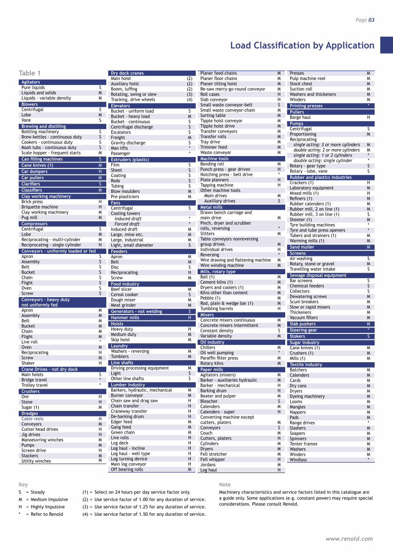
Load Classification by Application
Page 03
www.renold.com
Agitators Pure liquids S Liquids and solids M Liquids - variable density MBlowers Centrifugal S Lobe M Vane SBrewing and distilling Bottling machinery S Brew kettles - continuous duty S Cookers - continuous duty S Mash tubs - continuous duty S Scale hopper - frequent starts MCan filling machines SCane knives (1) MCar dumpers HCar pullers MClarifiers SClassifiers MClay working machinery Brick press H Briquette machine H Clay working machinery M Pug mill MCompressors Centrifugal S Lobe M Reciprocating - multi-cylinder M Reciprocating - single cylinder HConveyors - uniformly loaded or fed Apron S Assembly S Belt S Bucket S Chain S Flight S Oven S Screw SConveyors - heavy duty not uniformly fed Apron M Assembly M Belt M Bucket M Chain M Flight M Live roll * Oven M Reciprocating H Screw M Shaker HCrane Drives - not dry dock Main hoists S Bridge travel * Trolley travel *Crushers Ore H Stone H Sugar (1) MDredges Cable reels M Conveyors M Cutter head drives H Jig drives H Manoeuvring winches M Pumps M Screen drive H Stackers M Utility winches M
Dry dock cranes Main hoist (2) Auxiliary hoist (2) Boom, luffing (2) Rotating, swing or slew (3) Tracking, drive wheels (4)Elevators Bucket - uniform load S Bucket - heavy load M Bucket - continuous S Centrifugal discharge S Escalators S Freight M Gravity discharge S Man lifts * Passenger *Extruders (plastic) Film S Sheet S Coating S Rods S Tubing S Blow moulders M Pre-plasticiers MFans Centrifugal S Cooling towers Induced draft * Forced draft * Induced draft M Large, mine etc. M Large, industrial M Light, small diameter SFeeders Apron M Belt M Disc S Reciprocating H Screw MFood industry Beef slicer M Cereal cooker S Dough mixer M Meat grinder MGenerators - not welding SHammer mills HHoists Heavy duty H Medium duty M Skip hoist MLaundry Washers - reversing M Tumblers MLine shafts Driving processing equipment M Light S Other line shafts SLumber industry Barkers, hydraulic, mechanical M Burner conveyor M Chain saw and drag saw H Chain transfer H Craneway transfer H De-barking drum H Edger feed M Gang feed M Green chain M Live rolls H Log deck H Log haul - incline H Log haul - well type H Log turning device H Main log conveyor H Off bearing rolls M
Planer feed chains M Planer floor chains M Planer tilting hoist M Re-saw merry-go-round conveyor M Roll cases H Slab conveyor H Small waste conveyor-belt S Small waste conveyor-chain M Sorting table M Tipple hoist conveyor M Tipple hoist drive M Transfer conveyors M Transfer rolls M Tray drive M Trimmer feed M Waste conveyor MMachine tools Bending roll M Punch press - gear driven H Notching press - belt drive * Plate planners H Tapping machine H Other machine tools Main drives M Auxiliary drives SMetal mills Drawn bench carriage and main drive M Pinch, dryer and scrubber rolls, reversing * Slitters M Table conveyors nonreversing group drives M Individual drives H Reversing * Wire drawing and flattening machine M Wire winding machine MMills, rotary type Ball (1) M Cement kilns (1) M Dryers and coolers (1) M Kilns other than cement M Pebble (1) M Rod, plain & wedge bar (1) M Tumbling barrels HMixers Concrete mixers continuous M Concrete mixers intermittent M Constant density S Variable density MOil industry Chillers M Oil well pumping * Paraffin filter press M Rotary kilns MPaper mills Agitators (mixers) M Barker - auxiliaries hydraulic M Barker - mechanical H Barking drum H Beater and pulper M Bleacher S Calenders M Calenders - super H Converting machine except cutters, platers M Conveyors S Couch M Cutters, platers H Cylinders M Dryers M Fell stretcher M Fell whipper H Jordans M Log haul H
Presses M Pulp machine reel M Stock chest M Suction roll M Washers and thickeners M Winders MPrinting presses *Pullers Barge haul HPumps Centrifugal S Proportioning M Reciprocating single acting: 3 or more cylinders M double acting: 2 or more cylinders M single acting: 1 or 2 cylinders * double acting: single cylinder * Rotary - gear type S Rotary - lobe, vane SRubber and plastics industries Crackers (1) H Laboratory equipment M Mixed mills (1) H Refiners (1) M Rubber calenders (1) M Rubber mill, 2 on line (1) M Rubber mill, 3 on line (1) S Sheeter (1) M Tyre building machines * Tyre and tube press openers * Tubers and strainers (1) M Warming mills (1) MSand muller MScreens Air washing S Rotary, stone or gravel M Travelling water intake SSewage disposal equipment Bar screens S Chemical feeders S Collectors S Dewatering screws M Scum breakers M Slow or rapid mixers M Thickeners M Vacuum filters MSlab pushers MSteering gear *Stokers SSugar industry Cane knives (1) M Crushers (1) M Mills (1) MTextile industry Batchers M Calenders M Cards M Dry cans M Dryers M Dyeing machinery M Looms M Mangles M Nappers M Pads M Range drives * Slashers M Soapers M Spinners M Tenter frames M Washers M Winders M Windlass *
Table 1
KeyS = Steady
M = Medium Impulsive
H = Highly Impulsive
* = Refer to Renold
(1) = Select on 24 hours per day service factor only.
(2) = Use service factor of 1.00 for any duration of service.
(3) = Use service factor of 1.25 for any duration of service.
(4) = Use service factor of 1.50 for any duration of service.
NoteMachinery characteristics and service factors listed in this catalogue are a guide only. Some applications (e.g. constant power) may require special considerations. Please consult Renold.
Service Factors and Selection
Page 04
Renoldflex Couplings
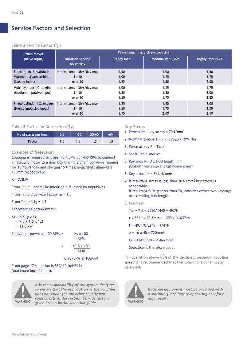
Example of Selection Coupling is required to transmit 7.5kW at 1440 RPM to connect an electric motor to a gear box driving a chain conveyor running for 18 hours/day and starting 15 times/hour. Shaft diameters /55mm respectively.
K = 7.5kW
From Table 1 Load Classification = M (medium impulsive)
From Table 2 Service Factor fD = 1.5
From Table 3 fS = 1.2
Therefore selection kW is:-
Ks = K x fD x fS = 7.5 x 1.5 x 1.2 = 13.5 kW
Equivalent power at 100 RPM = Ks x 100 RPM
= 13.5 x 100 1440
= 0.9375kW @ 100RPM
From page 17 selection is RSC110 (644911) (maximum bore 55 mm).
Key Stress 1. Permissible key stress = 70N/mm2
2. Nominal torque TKM = K x 9550 / RPM Nm
3. Force at key F = TKM /r
4. Shaft Rad r. metres
5. Key area A = J x HUB length mm (Obtain from relevant catalogue page).
6. Key stress fk = F/A N/mm2
7. If resultant stress is less than 70 N/mm2 key stress is acceptable. If resultant fk is greater than 70, consider either two keyways or extending hub length.
8. Example:
TKM = 7.5 x 9550/1440 = 49.7Nm
r = 55/2 = 27.5mm ÷ 1000 = 0.0275m
F = 49.7/0.0275 = 1741N
A = 16 x 45 = 720mm2
fk = 1741/720 = 2.4M/mm2
Selection is therefore good.
For operation above 80% of the declared maximum coupling speed it is recommended that the coupling is dynamically balanced.
Prime mover Driven machinery characteristics
(Drive input) Duration service Steady load Medium impulsive Highly impulsive hours/day
Electric, air & hydraulic Intermittent – 3hrs/day max 0.90 1.00 1.50 Motors or steam turbine 3 - 10 1.00 1.25 1.75 (Steady input) over 10 1.25 1.50 2.00
Multi-cylinder I.C. engine Intermittent – 3hrs/day max 1.00 1.25 1.75 (Medium impulsive input) 3 - 10 1.25 1.50 2.00 over 10 1.50 1.75 2.25
Single-cylinder I.C. engine Intermittent - 3hrs/day max 1.25 1.50 2.00 (Highly impulsive input) 3 - 10 1.50 1.75 2.25 over 10 1.75 2.00 2.50
Table 2 Service Factor (fD)
No of starts per hour 0-1 1-30 30-60 60-
Factor 1,0 1,2 1,3 1,5
Table 3 Factor for Starts/Hour(fS)
It is the responsibility of the system designer to ensure that the application of the coupling does not endanger the other constituent components in the system. Service factors given are an initial selection guide.
!WARNING
Rotating equipment must be provided with a suitable guard before operating or injury may result.
!WARNING

Key and Keyway Dimensions
Page 05
www.renold.com
Metric (mm)
Keyways comply with BS4235: Part 1: 1972
Shaft dia. Key & keyway
Over Incl. J K L 6 8 2 2 1.0 8 10 3 3 1.4 10 12 4 4 1.8 12 17 5 5 2.3 17 22 6 6 2.8 22 30 8 7 3.3 30 38 10 8 3.3 38 44 12 8 3.3 44 50 14 9 3.8 50 58 16 10 4.3 58 65 18 11 4.4 65 75 20 12 4.9 75 85 22 14 5.4 85 95 25 14 5.4 95 110 28 16 6.4 110 130 32 18 7.4 130 150 36 20 8.4 150 170 40 22 9.4 170 200 45 25 10.4 200 230 50 28 11.4
Imperial (inches)
Keyways comply with BS46: Part 1: 1958
Shaft dia. Key & keyway
Over Incl. J K L 0.25 0.05 0.125 0.125 0.060 0.50 0.75 0.187 0.187 0.088 0.75 1.00 0.250 0.250 0.115 1.00 1.25 0.312 0.250 0.090 1.25 1.50 0.375 0.250 0.085 1.50 1.75 0.437 0.312 0.112 1.75 2.00 0.500 0.312 0.108 2.00 2.50 0.625 0.437 0.162 2.50 3.00 0.750 0.500 0.185 3.00 3.50 0.875 0.625 0.245 3.50 4.00 1.000 0.750 0.293 4.00 5.00 1.250 0.875 0.340 5.00 6.00 1.500 1.000 0.384
Keyway dimensions [ fig 01 ] Parallel keyways are supplied unless customer states otherwise.
L
J
[ fig 01 ]
K
L
J
pag
e 8
A/W
’s
K
Renoldflex
Page 06
Renoldflex Couplings
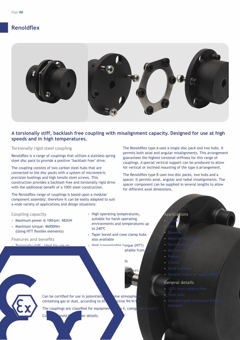
Torsionally rigid steel coupling
Renoldflex is a range of couplings that utilizes a stainless spring steel disc pack to provide a positive ‘backlash free’ drive.
The coupling consists of two carbon steel hubs that are connected to the disc packs with a system of micrometric precision bushings and high tensile steel screws. This construction provides a backlash free and torsionally rigid drive with the additional benefit of a 100% steel construction.
The Renoldflex range of couplings is based upon a modular component assembly; therefore it can be easily adapted to suit a wide variety of applications and design situations:
The Renoldflex type A uses a single disc pack and two hubs. It permits both axial and angular misalignments. This arrangement guarantees the highest torsional stiffness for this range of couplings. A special vertical support can be produced to allow for vertical or inclined mounting of the type A arrangement.
The Renoldflex type B uses two disc packs, two hubs and a spacer. It permits axial, angular and radial misalignments. The spacer component can be supplied in several lengths to allow for different axial dimensions.
A torsionally stiff, backlash free coupling with misalignment capacity. Designed for use at high speeds and in high temperatures.
Coupling capacity• Maximum power @ 100rpm: 482kW
• Maximum torque: 46000Nm (Using HTT flexible elements)
Features and benefits• Torsionally stiff – ideal for use on
precision machines
• 100% maintenance free – long life with little wear
• Misalignment capabilities allowing flexibility in installation
• Zero backlash guarantees operational accuracy
• High operating temperatures, suitable for harsh operating environments and temperatures up to 240ºC
• Taper bored and cone clamp hubs also available
• High transmissible torque (HTT) flexible elements available from size 70 up
• High operating speeds
Standard range comprises• Shaft to Shaft
• Spacer type
Applications• Pumps
• Fans
• Blowers
• Material handling
• Servo motor drives
• Machine tools
• Presses
• Cranes
• Wind turbines
• General industrial applications
General details• 100% steel construction
• Steel hubs
• Stainless steel laminated flexible elements
Can be certified for use in potentially explosive atmospheres containing gas or dust, according to ATEX directive 94/9/EC.
The couplings are classified for equipment group II, categories 2 and 3.
Contact Renold for further details.
Renoldflex
Page 07
www.renold.com
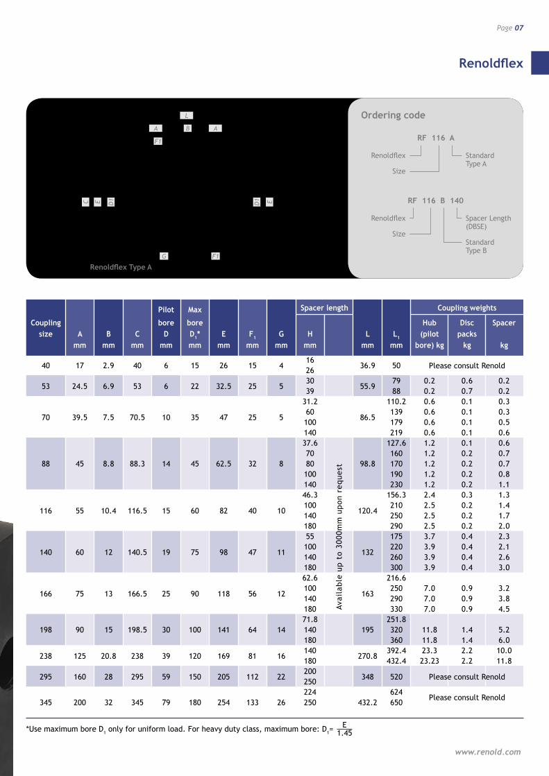
Pilot Max Spacer length Coupling weights
Coupling bore bore Hub Disc Spacer size A B C D D1* E F1 G H L L1 (pilot packs mm mm mm mm mm mm mm mm mm mm mm bore) kg kg kg
40 17 2.9 40 6 15 26 15 4
16 36.9
50
26
53 24.5 6.9 53 6 22 32.5 25 5 30
55.9 79 0.2 0.6 0.2
39 88 0.2 0.7 0.2 31.2 110.2 0.6 0.1 0.3
70 39.5 7.5 70.5 10 35 47 25 5 60
86.5 139 0.6 0.1 0.3
100 179 0.6 0.1 0.5 140 219 0.6 0.1 0.6 37.6 127.6 1.2 0.1 0.6 70 160 1.2 0.2 0.7 88 45 8.8 88.3 14 45 62.5 32 8 80 98.8 170 1.2 0.2 0.7 100 190 1.2 0.2 0.8 140 230 1.2 0.2 1.1 46.3 156.3 2.4 0.3 1.3
116 55 10.4 116.5 15 60 82 40 10 100
120.4 210 2.5 0.2 1.4
140 250 2.5 0.2 1.7 180 290 2.5 0.2 2.0 55 175 3.7 0.4 2.3
140 60 12 140.5 19 75 98 47 11 100
132 220 3.9 0.4 2.1
140 260 3.9 0.4 2.6 180 300 3.9 0.4 3.0 62.6 216.6
166 75 13 166.5 25 90 118 56 12 100
163 250 7.0 0.9 3.2
140 290 7.0 0.9 3.8 180 330 7.0 0.9 4.5 71.8 251.8 198 90 15 198.5 30 100 141 64 14 140 195 320 11.8 1.4 5.2 180 360 11.8 1.4 6.0
238 125 20.8 238 39 120 169 81 16 140
270.8 392.4 23.3 2.2 10.0
180 432.4 23.23 2.2 11.8
295 160 28 295 59 150 205 112 22 200
348
520 250 224 624 345 200 32 345 79 180 254 133 26 250 432.2 650
Avai
lab
le u
p t
o 30
00m
m u
pon
req
uest
*Use maximum bore D1 only for uniform load. For heavy duty class, maximum bore: D1= 1.45E
EC
L
F1
A B A
D1
F1G1
D E
B
L1
1DEC
F1
A H AB
F G
1D E
F1
B
L1
1DEC
F1
A H A
GG
B
1D E
L
A B
F1
A
D1EC D1 E
G F1
Renoldflex Type A
Ordering code
RF 116 A
Renoldflex
Size
Standard Type A
RF 116 B 140
Renoldflex
Size
Spacer Length (DBSE)
Standard Type B
Please consult Renold
Please consult Renold
Please consult Renold

Renoldflex
Page 08
Renoldflex Couplings
RENOLDFLEX TYPE A Single disc pack
RENOLDFLEX TYPE B Double disc pack
TORSIONAL STIFFNESS***
Size Nominal Max Misalignment Inertia Spacer Misalignment Inertia Disc pack Spacer Torque Speed Δ Δ Δ J length Δ Δ Δ J CK CH CTOT
T* V** radial axial angular H radial axial angular 106 Nm Nm rpm
offset ±mm [°] kg m2 mm
offset ±mm [°] kg m2 Nm/rad mm/rad Nm/rad mm mm
40 18 12000 0 0.4 0.75 0.00002 16 0.2
0.8 1.75 0.00005
Please consult Renold 26 0.3 0.00004
53 75 10000 0 0.4 0.75 0.00011 30 0.3
0.8 1.5 0.00016 113406 56703
39 0.4 0.00019 4.1 41988.45 31.2 0.3 0.00071 71232
70 170 8400 0 0.5 0.75 0.00049 60 0.7
1.1 1.5 0.00076 142464 56065.02
100 1.2 0.00081 11.8 47142.56 140 1.4 0.00087 40670.11 37.6 0.4 0.00218 100130 70 0.8 0.00252 90889.35 88 320 6800 0 0.6 0.75 0.00164 80 0.9 1.2 1.5 0.00256 200260
51.6 89316.32
100 1.2 0.00265 86328.13 140 1.7 0.00282 80913.99 46.3 0.5 0.00795 170832.5
116 750 5400 0 0.8 0.75 0.00991 100 1.2
1.6 1.5 0.00928
341665 154769.46
140 1.7 0.00986 130.4 147752.84 180 2.2 0.01047 141344.84 55 0.7 0.01824
140 1350 4600 0 1 0.75 0.01359 100 1.1
2.1 1.5 0.02093
503858 233020.5
140 1.7 0.02179 236 224165.39 180 2.2 0.02264 215958.66 62.6 0.7
166 2400 3800 0 1.2 0.75 0.0345 100 1.1
2.5 1.5 0.05175
938363 442511.2
140 1.7 0.05379 576.1 429319.64 180 2.2 0.05584 416891.81 71.8 0.7 198 4000 3400 0 1.4 0.75 0.08368 140 1.6 2.8 1.5 0.12413 1258733
959.8 587023.07
180 2.2 0.12736 573004.37
238 6500 3000 0 1.7 0.75 0.22773 140 1.6
3.4 1.5 0.33419
2268097 1807 1068089.47
180 2.1 0.34564 1043419.61
295 21000 2500 0 1.1 0.5 0.7 200 1.4
2.2 1 1.07
Please consult Renold 250 1.8 1.1 224 1.6 2.62 345 36000 2100 0 1.3 0.5 1.75 250 1.8 2.6 1 2.64 Please consult Renold 300 2.2 2.68
Avai
lab
le u
p t
o 30
00m
m u
pon
req
uest
EC
L
F1
A B A
D1
F1G
1D E
B
L1
1DEC
F1
A H AB
F G
1D E
F1
B
L1
1DEC
F1
A H A
GG
B
1D E
L1
B
A H
B
F1
D1EC D1 E
GF
A
D1EC
L1
B
A H
F1
G GF1
B
A
D1 E
Renoldflex Type B H-MIN Renoldflex Type B

Renoldflex
Page 09
www.renold.com
Renoldflex coupling size selection
In order to select the most suitable sized coupling, a number of service factors must be taken into consideration. These service factors make adjustments to the design torque (T) of an application to take into account factors such as misalignment, load classification, driver classification as well as high ambient temperatures to produce a selection torque (TS, where TS = T x fS). The most suitable coupling is then selected by comparing the selection torque (TS) and the couplings nominal torque (TN). Please note – it is important to ensure that the coupling selected will accept the required shaft diameters. Should shaft diameter exceed the maximum permissible then a larger coupling should be selected.
The total service factor fS = f1x f2 x f3; where f1 is the misalignment factor, f2 is the load classification factor and f3 is the temperature factor. Note; the load classification factor is weighted depending upon the prime mover classification. These service factors are defined below:
Misalignment factor f1
The maximum misalignments quoted within the technical data for the Renoldflex coupling range cannot be present at the same time. Therefore, the presence of any axial misalignment ∆ax reduces the possibility for offset misalignment ∆rad and angular misalignment ∆ang, which can be seen in [ fig 02 ]. The combined total angular misalignment ∆TOT is a function of the angular misalignment ∆ang and offset misalignment ∆rad of the shafts, according to the following formula:
∆TOT [°]= ∆ang + arctan ∆rad
The values H and B [mm] are given in the overall dimensions table. The misalignment factor f1 is a function of ∆TOT as shown in [ fig 03 ].
Load factor f2
The following load factors apply for machines operated by electric or hydraulic motors as well as steam or gas turbines.
load factor OPERATING MACHINE f2
Blowers: low inertia 1.1
Blowers: high inertia, cooling towers 2.0
Centrifugal pumps: low inertia and light liquids 1.1
Centrifugal pumps: high inertia or semi-liquid materials 1.75
Conveyors 1.5
Elevators and cranes 2.0
Gear pumps 1.5
Machine tools: auxiliary drives 1.1
Machine tools: main drives 1.75
Mills 2.5
Paper machines and textile machines 2.0
Presses 3.0
Reciprocating pumps 2.5
Woodworking machines 1.5
For machines operated by alternative prime movers the load factor f2 must be adjusted as follows:
• f2+1 for machines operated by IC engines with 4 or 5 pistons.
• f2+0.5 for machines operated by IC engines with 6 pistons, hydraulic turbines or with a start torque >2.
• The following must be taken into account with regard to repetitive high peak torque applications:
• For non reversing duty: T> Peak torque
• For reversing duty: T> 1.5 Peak torque.
Temperature factor f3
Renoldflex couplings are unaffected by temperatures up to 160°C. For applications with higher temperatures, the temperature factor f3 seen in [ fig 04 ] must be taken into consideration.
(H-B)2
100
80
60
40
20
00 20 40 60 80 100
0
%52
%05
%57
∆ ]
%[ .D
AR
tn emngila si
m tes ffO
∆ AX. [%] Axial misalignment
∆ ANG. [%]Angular misalignment
Note: Allowance should be made for changein misalignment encountered during operation. e.g. due to thermalexpansion.
f1 Misalignment factor
0 0.2 0.4 0.6 0.8 11
1.2
1.4
1.6
1.8
2
∆ tot. [°]
Workpreferential area
0 60 120 180 240 [°C]
1
1.1
1.2
1.3
1.4
f 3Te
mpe
ratu
re f
acto
r
Working temperature
For applications withtemperatures over 80˚C this must bestated on order.
[ fig 02 ] Misalignment diagram [ fig 03 ] Misalignment factor f1[ fig 04 ] Temperature factor f2

Renoldflex
Page 10
Renoldflex Couplings
* Renoldflex allows 1.75 times the nominal torque for short periods of time.
** See [ fig 05 ] & [ fig 06 ]. *** The torsional stiffness of a single pack
complete coupling can be approximated to the torsional stiffness of 1 disc pack Ck
The torsional angle of a single pack coupling
[°] = 180 T π Ck
The torsional stiffness of a complete double pack coupling can be approximated to: CTOT = 1 H,B – see catalogue overall dims 2 + H-2B Ck Ch
The torsional angle of a double pack coupling
[°] = 180 T π Ck
T (Nm) – Transmitted torque
H = Spacer length
rpm
0
250
500
1000
1500
1750
1250
750
0
Dynamic balancingsuggested.
Balancing not necessary.
250 500 750 1000 1250 1500 1750 2000
Size
0
4500
4000
3500
3000
2500
2000
1500
1000
500
40 72 89 118 142 168 200 23853
rpm
Balancing not necessary.
Dynamic balancingsuggested.
Balancing; Renoldflex standard elements are balanced to grade G6.3 - BS ISO 1940-1:2003. Additional balancing is recommended for applications over the speed curves in [ fig 05 ] and [ fig 06 ].
[ fig 05 ] Balancing
Renoldflex Type A
[ fig 06 ] Balancing
Renoldflex Type B
Type E Type F
Type G Type HH min
Type L Type MM min
Type M Type P
Type H
Type N
Other Renoldflex Types available (Please consult Renold)

• High performance
• Superior wear life
• Outstanding fatigue resistance
• Best premium chain
• Leading performance
• Solid bush / solid roller /end softened pin
• Manufactured to international stds
• Full range of pitch alternatives
• Breaking loads 13 to 900 kN as std
• Attachments to suit varied applications
• Superior corrosion resistant coating
• Alternative choice to stainlesssteel chain
• Will not chip or peel
• Hexavalent chrome-free
• Comprehensive ranges used worldwidefor safety critical lifting applications
• 100 years experience in developing andmaintaining lifting chain
Hydro-Service™
Leaf Chain
™
www.renold.com
• Heavy duty, detachable elevatorchains
• Integral K type attachments
• Breaking loads from 642kNto 1724kN
• Sealed joint to extend chain life
• Wide range to suit specialisedapplications using high specificationmaterials and treatment processes
• Designed in close collaborationwith customer
• Revolutionary chain tensioner
• Installed in seconds andself adjusting
• Maintenance free
• Also acts as noise damper
Roll-Ring™
• Load monitoring technology
• Technical reports & data logging
Smartlink™
Steel PinBush Roller Chain
Steel Knuckle Chain
CustomisedEngineering Chain
The best range of solution chain products available anywhere
• Maintenance free
• Self-lubricating chain
• Food industry-approved lubricant
36073 A4 1pp chain overview.qxd:A4 30/6/10 13:09 Page 1

www.renold.com
AUSTRALIA Melbourne (Victoria) Tel + 61 (03) 9262 3333 Fax + 61 (03) 9561 8561 also at: Sydney, Brisbane, Adelaide, Perth, Newcastle, Wollongong, Townsville
AUSTRIA Vienna Tel + 43 (0) 13303484 0 Fax + 43 (0) 13303484 5
BELGIUM Brussels Tel + 32 (0) 2 201 1262 Fax + 32 (0) 2 203 2210
CANADA Brantford (Ontario) Tel + 1 519 756 6118 Fax + 1 519 756 1767 also at: Montreal
CHINA Shanghai Tel + 86 21 5046 2696 Fax + 86 21 5046 2695
CZECH REPUBLIC Jaroslavice Tel + 42 67 7211074 Fax + 42 67 7211074
DENMARK Brøndby (Copenhagen) Tel + 45 43 452611 Fax + 45 43 456592
FRANCE Seclin Tel + 33 (0) 320 16 29 29 Fax + 33 (0) 320 16 29 00 Calais (chain only) Tel + 33 (0) 321 97 99 45 Fax + 33 (0) 321 97 83 45
GERMANY Mechernich Tel + 49 (0) 2256 95 90 74 Fax + 49 (0) 2256 95 91 69 [email protected]
HUNGARY Budapest Tel + 36 30 228 3269 Fax + 36 1 287 808 [email protected]
INDIA Colmbatore Tel +91 422 2532 357 Tel +91 422 2532 358 [email protected]
MALAYSIA Petaling Jaya Tel + 603 5191 9880 Fax + 603 5191 9881 also at: Johor Bharu, Ipoh, Butterworth
NETHERLANDS Amsterdam Tel + 31 206 146661 Fax + 31 206 146391
NEW ZEALAND Auckland Tel + (0) 64 9 828 5018 Fax + (0) 64 9 828 5019 also at: Christchurch
SINGAPORE Singapore Tel + 65 6760 2422 Fax + 65 6760 1507
SOUTH AFRICA Benoni Tel + (0) 27 11 747 9500 Fax + (0) 27 11 747 9505 also at: Durban, Cape Town, Port Elizabeth, Witbank
SPAIN Renold Hi-Tec Couplings SA Tel + 34 93 6380558 Fax + 34 93 6380737 [email protected]
SWEDEN Brøndby (Copenhagen) Tel + 45 43 245028 Fax + 45 43 456592
SWITZERLAND Dübendorf (Zürich) Tel + 41 (0) 1 824 8484 Fax + 41 (0) 1 824 8411 also at: Crissier (Lausanne)
UK Renold Clutches & Couplings, Wales Tel + 44 (0) 29 20792737 Fax + 44 (0) 29 20791360 [email protected]
Renold Hi-Tec Couplings, Halifax Tel + 44 (0) 1422 255000 Fax + 44 (0) 1422 320273 [email protected]
Renold Gears, Milnrow Tel + 44 (0) 1706 751000 Fax + 44 (0) 1706 751001 [email protected]
USA Renold Ajax Westfield, New York Tel + 1 716 326 3121 Fax + 1 716 326 6121
WEB www.renold.com
E-MAIL [email protected]
For other country distributors please contact Renold UK or visit the renold website.
Whilst all reasonable care in compiling the information contained in this brochure is taken, no responsibility is accepted for printing errors. All information contained in this brochure is subject to change after the date of publication.
RE
V02
02/
12