renovation of the deck of a major listed bridge structure
TRANSCRIPT

Renovation of the deck of a major listed bridge structure
R. Brueckner & P. Lambert Mott MacDonald, Materials & Corrosion Engineering, United Kingdom
Abstract
The Silver Jubilee Bridge in the UK crosses the River Mersey between Runcorn and Widnes. It was completed in the early 1960s and is an English Heritage Grade II listed structure. It forms part of the major highway route in North West England and carries over 90,000 vehicles per day on four lanes. The original design carried a single lane in each direction, plus a single central shared overtaking lane. This was widened to carry two narrow lanes in each direction during the late 1970s. The central span of the bridge is a 330m long steel arch structure with two 76m side spans and is the largest of its type in Europe. The deck is reinforced concrete supported on structural steelwork. The original surfacing was hand placed mastic asphalt. This provided some degree of waterproofing, but remained in place for over 40 years until a new waterproofing and surfacing system was installed in 2005. By this time the bridge deck was heavily contaminated with chlorides from de-icing salts and the reinforcement was found to be corroding in many areas. To maintain and extend the functionality of the bridge, avoid major disruptions to this major river crossing over the Mersey and to preserve the Grade II listed character, it was necessary to identify a durable but sympathetic repair strategy. This paper will discuss the many options considered and the eventual adoption of a novel and subsequently award winning cathodic protection system specifically developed for this application. Keywords: cathodic protection, grade 2 listed, bridge, corrosion, concrete, steel, repair.
Structural Repairs and Maintenance of Heritage Architecture XII 307
www.witpress.com, ISSN 1743-3509 (on-line) WIT Transactions on The Built Environment, Vol 118, © 2011 WIT Press
doi:10.2495/ 10261STR1
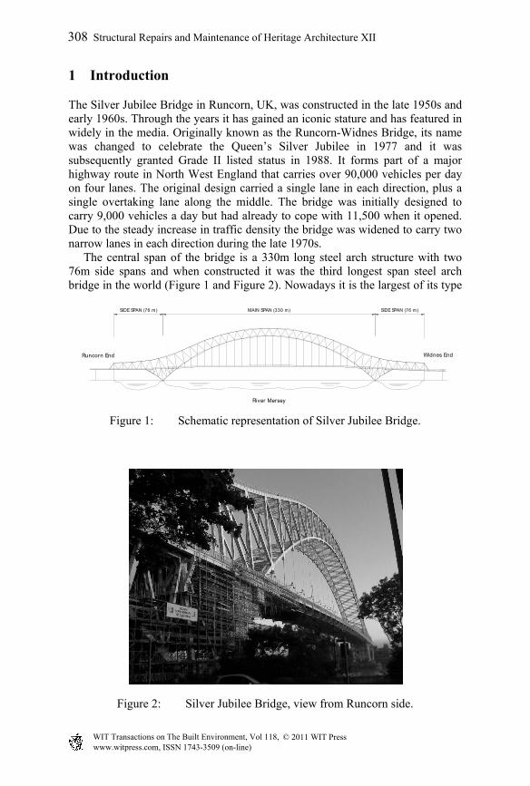
Runcorn End Widnes End
SIDE SPAN (76 m) MAIN SPAN (330 m) SIDE SPAN (76 m)
River Mersey
1 Introduction
The Silver Jubilee Bridge in Runcorn, UK, was constructed in the late 1950s and early 1960s. Through the years it has gained an iconic stature and has featured in widely in the media. Originally known as the Runcorn-Widnes Bridge, its name was changed to celebrate the Queen’s Silver Jubilee in 1977 and it was subsequently granted Grade II listed status in 1988. It forms part of a major highway route in North West England that carries over 90,000 vehicles per day on four lanes. The original design carried a single lane in each direction, plus a single overtaking lane along the middle. The bridge was initially designed to carry 9,000 vehicles a day but had already to cope with 11,500 when it opened. Due to the steady increase in traffic density the bridge was widened to carry two narrow lanes in each direction during the late 1970s. The central span of the bridge is a 330m long steel arch structure with two 76m side spans and when constructed it was the third longest span steel arch bridge in the world (Figure 1 and Figure 2). Nowadays it is the largest of its type Figure 1: Schematic representation of Silver Jubilee Bridge.
Figure 2: Silver Jubilee Bridge, view from Runcorn side.
308 Structural Repairs and Maintenance of Heritage Architecture XII
www.witpress.com, ISSN 1743-3509 (on-line) WIT Transactions on The Built Environment, Vol 118, © 2011 WIT Press

in Europe. The proportions of the main span of the bridge are approximately two thirds of that of the Sydney Harbour Bridge. The deck is constructed from reinforced concrete to the Ministry of Transport Specification of 1951, which required a cube strength of 24.8 MPa, and is supported on structural steelwork. The original surfacing was hand placed mastic asphalt. This provided some degree of waterproofing, but was left in place for over 40 years, until a new waterproofing and surfacing system was installed in 2005. By this time the bridge deck was heavily chloride contaminated and the reinforcement corroding in many areas. The original approach viaducts have four main beams supported by reinforced concrete piers. The ends of the beams were precast, and the central spans were cast in place at the same time as the deck. The approach spans are a total of 522m in length. The highways in this part of England are subjected to chloride-based de-icing salts during the winter months. Although the deck of the approach viaducts is waterproofed and has not degraded significantly, there are joints over every third pier that have degraded with time, allowing chloride-contaminated water to leak onto the substructure. Chlorides have penetrated the concrete cover, and chloride levels at the reinforcement have reached 2% by mass of cement, which is more than enough to cause corrosion.
2 Challenges and restrictions
The English Heritage Grade II listed status and its position as a major highway link impose significant restrictions upon those tasked with maintaining the structure. The bridge was listed in March 1988, despite its relatively young age, because it forms a structure of ‘special interest, warranting every effort to preserve it’ [1]. Structures, predominantly buildings, are usually listed because of age, rarity, architectural merit and method of construction. Occasionally structures are selected because they are directly associated with a famous person, or were the scene for an important event. In the 1950s and 1960s some 3,000 highway bridges were constructed and certain exceptional designs have been listed. English Heritage states in its guidelines that structural and aesthetic considerations will ultimately determine the listability. The status as a listed structure imposes certain restrictions, i.e. a listed building may not be demolished, extended or altered without special permission from the local planning authority. In the case of the Silver Jubilee Bridge, this includes the colour of the paintwork which may not be changed. The second restriction results from the importance of the bridge as a major highway link in the region. A closure would result in a diversion of at least 65 kilometres. Partial closure would result in heavy congestion combined with undesirable night work next to live traffic. Due to the lane width, traffic management with the current volume of traffic is difficult and inevitably disruptive. The risk of loss of availability of the bridge is such a significant
Structural Repairs and Maintenance of Heritage Architecture XII 309
www.witpress.com, ISSN 1743-3509 (on-line) WIT Transactions on The Built Environment, Vol 118, © 2011 WIT Press
restriction that a second structure, the Mersey Gateway, is to be constructed to run in parallel and take the majority of through traffic.
3 Concrete repair history
3.1 General
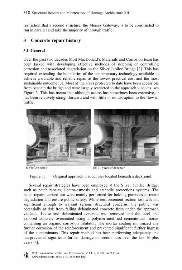
Over the past two decades Mott MacDonald’s Materials and Corrosion team has been tasked with developing effective methods of stopping or controlling corrosion and associated degradation on the Silver Jubilee Bridge [2]. This has required extending the boundaries of the contemporary technology available to achieve a durable and reliable repair at the lowest practical cost and the most sustainable outcome [3]. Most of the areas protected to date have been accessible from beneath the bridge and were largely restricted to the approach viaducts, see Figure 3. This has meant that although access has sometimes been extensive, it has been relatively straightforward and with little or no disruption to the flow of traffic.
(a) before repair (b) 10 years after repair
Figure 3: Original approach viaduct pier located beneath a deck joint.
Several repair strategies have been employed at the Silver Jubilee Bridge, such as patch repairs, electro-osmosis and cathodic protections systems. The patch repairs carried out were mainly performed for holding purposes to retard degradation and ensure public safety. While reinforcement section loss was not significant enough to warrant serious structural concerns, the public was potentially at risk from falling delaminated concrete from under the approach viaducts. Loose and delaminated concrete was removed and the steel and exposed concrete overcoated using a polymer-modified cementitious mortar containing an organic corrosion inhibitor. The mortar coating minimized any further corrosion of the reinforcement and prevented significant further ingress of the contaminants. This repair method has been performing adequately and has prevented significant further damage or section loss over the last 10-plus years [4].
310 Structural Repairs and Maintenance of Heritage Architecture XII
www.witpress.com, ISSN 1743-3509 (on-line) WIT Transactions on The Built Environment, Vol 118, © 2011 WIT Press

An electro-osmosis system was developed to control moisture levels in a pier of the bridge by the application of controlled low voltage DC pulses. The system is capable of reducing moisture levels in concrete to between 60% and 70% RH, and maintaining this level irrespective of external weather conditions. An additional benefit to the removal of excess free moisture is the associated reduction in dissolved salts, particularly chloride, present within the pore solution of the concrete, with the overall effect of reducing chloride ions to below critical levels with respect to chloride-induced corrosion. The system is also designed to negatively polarise the reinforcement resulting in a degree of cathodic protection, helping to reduce the corrosion risk of embedded steel during the transition period from high to low relative humidity (typically several months), and providing additional protection throughout the life of the installation [5].
3.2 Mesh and overlay CP
The first cathodic protection system was installed in 1993 and represented the first commercial use of coated titanium mesh with a dry-mix gunite overlay for CP systems in the United Kingdom. The basic mesh and overlay system was also used on the next two contracts but in 1998 another innovative approach, a hybrid system, was used. This hybrid system combined discrete anodes with mesh and overlay. In an at the time unusual step, dry-mix gunite was used for the concrete repairs, while wet-mix gunite was used for the overlay to minimize dust and noise disruption to a neighbouring school. In 2000 a CP system and patch repairs were used during a repair contract which included extensively contaminated areas next to the abutment and locally affected areas at the highest sections of the approach viaducts. To reduce costs, locally affected areas with difficult access were patch repaired using hand-applied mortar containing corrosion inhibitor to protect against incipient anode effect. The systems installed after 2000 had their designs optimised by reviewing the operating criteria of the existing systems. By employing this technique it was possible to reduce the quantity of anodes used, in some cases by a factor of 3. In addition, the lower current demand allowed larger zones to be used, which reduces the number of monitoring probes and power supplies. As an example one system installed in 1995 used 7 zones to protect one 30m long beam. Four of these zones had multiple layers of anode mesh. There were 24 reference electrodes and 6 graphite potential probes installed. In 2005 four similar beams were protected as a single zone, with a single layer of mesh anode and 4 reference electrodes. The mesh and overlay CP installation added approximately 25mm of gunite to each face of the piers but the original features of the piers were reinstated so that no significant alteration to the appearance occurred. The control units were installed above each pier at the longitudinal beams to protect them from accidental damage or vandalism and to hide them from view.
Structural Repairs and Maintenance of Heritage Architecture XII 311
www.witpress.com, ISSN 1743-3509 (on-line) WIT Transactions on The Built Environment, Vol 118, © 2011 WIT Press

3.3 Deck protection
The heavily chloride contaminated bridge deck was the last major element to be protected. There were limitations in respect of the suitability and accessibility in addition to the restrictions imposed by the Grade II listed status and the possible disruption to the local economy. The bridge deck is 40m above the River Mersey and the Manchester Ship Canal and traffic management is restricted. A mesh and overlay system would certainly be able to provide the current, but the vibrations in the deck caused by traffic would mean there was a risk that the sprayed concrete overlay could debond. Discrete anodes could be installed by roped access, but would require drilling holes into the deck at depth. If the holes were drilled marginally too deep there was a risk of drilling into live traffic. A galvanic system as previously installed in combined systems would fall under the same restriction. The application of corrosion inhibitors could provide a time limited protection but a durable solution was required. The only other established solution would involve the removal and replacement of the bridge deck which is the most common approach to the maintenance of such structures. For heritage structures the aim is to replace elements with like for like materials. Aside from the traffic chaos associated with its closure, the environmental consequences of such extensive work over a water way could not be tolerated. In addition to the carbon footprint based on the embodied energy, the associated disruption to traffic and the local population had to be considered. What was needed was an effective and sympathetic system that could provide the required protection to preserve the structure, minimise disruptions and avoid significant alteration to the appearance of the bridge. To fulfil all these requirements it was necessary to find an appropriate compromise and this was identified as an anode system that could be securely surface mounted without the need for extensive breakout, surface preparation or drilling. After considerable research, a cassette system originally designed for installation on jetties and harbours was identified as showing promise. The anodes sit in a fibreglass foam-filled GRP tray which can be mounted on a concrete surface using sleeved bolts, see Figure 4. In the environment of jetties and harbours the foam never dries out as it is wetted by the tide but on the bridge this would not happen. Moisture is necessary to act as an ionic transport medium for the current to the protected reinforcement. Further refinements were made to the cassette system based on the requirement to protect a bridge deck 40 meters above water level. This resulted in the development of a calcium nitrate based impregnation for the glassfibre foam which is able to retain moisture simply by being in contact with the atmosphere. The various authorities accepted the proposal of a trial installation on a 60m section of the bridge deck. Cassettes were installed at 500mm centres, which, based on past experience, is considered to be the maximum allowable spacing for the anodes. The monitoring data from the initial 12 months showed the trial section was performing as designed, and the remaining 280m of the deck were protected with the same system, the final section being energised in December 2010.
312 Structural Repairs and Maintenance of Heritage Architecture XII
www.witpress.com, ISSN 1743-3509 (on-line) WIT Transactions on The Built Environment, Vol 118, © 2011 WIT Press

Figure 4: Cassette System installed on deck soffit.
The installed cassettes do not adversely affect the appearance of the structure. The cassettes are visible but the view from underneath the bridge is dominated by the steel work as seen in Figure 5.
Figure 5: Installed cassettes.
GRP casing
Mixed Metal Oxide Coated Titanium Ribbon Anode
Sleeved insulated stainless steel bolts @ 500mm c/c
Glass fibre pad impregnated with calcium nitrate
Structural Repairs and Maintenance of Heritage Architecture XII 313
www.witpress.com, ISSN 1743-3509 (on-line) WIT Transactions on The Built Environment, Vol 118, © 2011 WIT Press
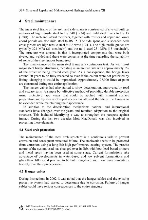
4 Steel maintenance
The main steel frame of the arch and side spans is constructed of riveted built up sections of high tensile steel to BS 548 (1934) and mild steel rivets to BS 15 (1948). The web and lateral members, together with trestles and upper and lower chord portals are also mild steel to BS 15. The side spans and suspended deck cross girders are high tensile steel to BS 9968 (1941). The high tensile grades are typically 324 MPa (21 tons/inch2) and the mild steel 231 MPa (15 tons/inch2). The structure was unusual in that it incorporated components that were both riveted and welded and there were concerns at the time regarding the suitability of some of the steel grades being used. The maintenance of the main steel frame is a continuous task. As with most major steel bridge structures, recoating is an annual task with approximately 5% of the structure being treated each year. As a consequence, the bridge takes around 20 years to be fully recoated so even if the colour were not protected by listing, changing it would be impractical. Approximately 27,000 litres of paint are consumed during one entire application. The hanger cables had also started to show deterioration, aggravated by road and estuary salts. A simple but effective method of providing durable protection using protective tape wraps that could be applied with minimal surface preparation and by means of roped access has allowed the life of the hangers to be extended while maintaining their appearance. In addition to the deterioration mechanisms national and international standards have changed over the years and required adaptation to the original structure. This included identifying a way to strengthen the parapets against impact. During the last two decades Mott MacDonald was also involved in protecting these elements.
4.1 Steel arch protection
The maintenance of the steel arch structure is a continuous task to prevent corrosion and consequent structural failure. The steelwork needs to be protected from corrosion using a long life high performance coating system. The precise nature of the system used has changed over its life, with both lead-based primers and metal spray having been used at some stage. Current formulations take advantage of developments in water-based and low solvent formulations and glass flake fillers and promise to be both long-lived and more environmentally friendly than their predecessors.
4.2 Hanger cables
During inspections in 2002 it was noted that the hanger cables and the existing protective system had started to deteriorate due to corrosion. Failure of hanger cables could have serious consequences to the entire structure.
314 Structural Repairs and Maintenance of Heritage Architecture XII
www.witpress.com, ISSN 1743-3509 (on-line) WIT Transactions on The Built Environment, Vol 118, © 2011 WIT Press

Figure 6: Steel arch and hanger cables.
The proposed repair method was firstly tested in a full-scale trial and comprised the use of a corrosion-inhibiting tape system which is applied to the cables using roped access, see Figure 6 and Figure 7. Where additional protection was required, such as at the connections between the hangers and bridge deck, a zinc-hydrogel tape was applied under the protective tape wrap. The trial confirmed the feasibility of the system and also provided significant benefits to the client. Using roped access high costs due to scaffolding and disruptions to the traffic because of lane closure was avoided. The program could also be shortened with the same level of safety and quality.
Figure 7: Hanger cables being protected.
All 24 cables on the bridge’s East elevation were wrapped during 2008 and the cables on the West elevation were finished in 2009. Additionally colour-
Structural Repairs and Maintenance of Heritage Architecture XII 315
www.witpress.com, ISSN 1743-3509 (on-line) WIT Transactions on The Built Environment, Vol 118, © 2011 WIT Press

matched protective cowlings for the cable anchorages and anti-vandal sheaths to protect the cables adjacent to the footway were designed and installed.
4.3 Parapet strengthening
An assessment of the bridge in 2001 identified that, due to the substandard nature of the existing parapets (Figure 8 (a)), the hanger cables were vulnerable to vehicle impact in addition to the risk of corrosion. Accidents could cause catastrophic failure of the entire structure if hanger cables are hit. A parapet system was designed to withstand the impact in accordance with current standards while recognizing the sensitivity of the structure to change and disruption. Conventional parapet replacement, by anchoring the parapet into the reinforced concrete deck, would have involved significant breaking and re-casting of the deck to provide an anchorage able to resist the substantial impact loads from the parapets. This would require long duration lane closures and consequent major disruption to the region and, potentially, gridlock the network in the North West. An innovative solution was developed which uses a system of sub-deck anchorage steelwork that is directly connected to the deck-supporting longitudinal girders, see Figure 8 (b). This solution avoided the breakout of concrete from the deck and allowed the existing steel kerbs to be retained. All four lanes could be kept open for the traffic. The only lane closures required were short duration night-time closures to allow installation of new posts and rails.
(a) Existing parapet
(b) New parapet (before painting)
Figure 8: Refurbished parapet at SJB.
316 Structural Repairs and Maintenance of Heritage Architecture XII
www.witpress.com, ISSN 1743-3509 (on-line) WIT Transactions on The Built Environment, Vol 118, © 2011 WIT Press

5 Conclusions
The restrictions imposed by the listing of the Silver Jubilee Bridge have proved to be an effective incentive in development of innovative and sympathetic remediation techniques. The low levels of intrusion typically associated with such techniques often means they have also offered sustainable and environmentally friendly alternatives to conventional repair. This has been recognised by the award of several national and international prizes for sustainability and longevity. The lessons and techniques developed to protect and extend the life of the Silver Jubilee Bridge have been transferred to other structures, the majority of which were not listed or considered historically important, but have benefited from the improved remediation technology.
Acknowledgement
The authors acknowledge the assistance and support provided by Halton Borough Council and wish to thank them for permitting the publication of this paper.
References
[1] English Heritage, www.english-heritage.org.uk/content/publications/docs/ transportselectionguide.pdf
[2] Coull, Z.L., Atkins, C.P., Lambert P. & Chrimes, J., The Evolution of Reinforced Concrete Repair Techniques at the Silver Jubilee Bridge. Latincorr, Universidad de Santiago de Chile, 2003.
[3] Lambert, P. & Atkins, C., Maintaining the Silver Jubilee Bridge – Cathodic protection for a critical causeway, Concrete International, 2007.
[4] Baldwin, N.J.R. & King, E.S., Field Studies of the Effectiveness of Concrete Repairs, Phase 4 Report: Analysis of the Effectiveness of Concrete Repairs and Project Findings. Research Report 186, Health and Safety Executive, Sudbury, UK, 2003.
[5] Lambert, P., Controlling Moisture, Construction Repair: Concrete Repairs 6, 1997.
Structural Repairs and Maintenance of Heritage Architecture XII 317
www.witpress.com, ISSN 1743-3509 (on-line) WIT Transactions on The Built Environment, Vol 118, © 2011 WIT Press