repair manual fifth-wheel coupling jsk 38/50 · repair manual fifth-wheel coupling jsk 38/50 ......
TRANSCRIPT
1ZDE 199 003 012 E 06/2005
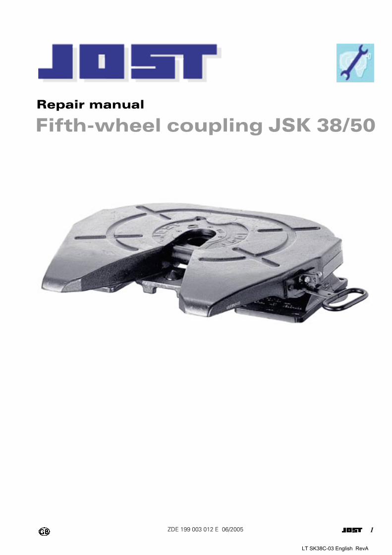
Repair manual
Fifth-wheel coupling JSK 38/50
LT SK38C-03 English RevA
2ZDE 199 003 012 E 06/2005
Foreword Table of contents Page
Fifth wheel couplings are connecting parts that must comply with very high safety requirements and must also undergo design approval tests.
This repair manual is designed to act as a guide to completing repair work to our fifth wheel cou-plings. It is essential that you use JOST spare parts to do this work.
Modifications for any kind will render both the war-ranty and the type approval void.
Instructions for the operation and installation of the fifth wheel couplings and the permitted load data for them are provided in separate documents.
1 Safety instructions .............................. 3
2 Troubleshooting .................................. 4
3 Standard and special tools and operating media .................................. 5
3.1 Standard tools ...........................................53.2 Special tools..............................................53.3 Operating media .......................................5
4 Repair work ......................................... 6
4.1 To remove and install pedestal version JSK 38 C ...................................................7
4.2 To remove and install pedestal version JSK 38 G ...................................................9
4.3 To remove and install pedestal version JSK 50.....................................................12
4.4 To remove rocker arm version JSK 38 G 134.5 To install rocker arm version JSK 38 G ...154.6 To remove and install rocker arm
bearing version JSK 38 G........................184.7 To remove and install the locking
mechanism .............................................204.8 To remove and install the wearing ring...214.9 To remove and install the lock jaw..........224.10 To remove and install the lock................254.11 To remove and install the latch
mechanism ............................................264.12 To remove and install the catch
mechanism on version JSK 38 G ...........264.13 To adjust the locking mechanism...........284.14 Wear limit, adjustment and inspection
dimensions..............................................28
5 Spare parts for version JSK 38 C ...... 31
6 Spare parts list for version JSK 38 G 33
7 Spare parts list for version JSK 50 ... 36
8 Waste disposal instructions .............. 38
LT SK38C-03 English RevA
3ZDE 199 003 012 E 06/2005
1Safety instructions
The relevant safety regulations in your country (for example Health + Safety at work) apply for working with fifth wheel couplings and tractor units.
The appropriate safety instructions in the tractor unit and trailer owner’s handbooks are to be followed.
LT SK38C-03 English RevA
4ZDE 199 003 012 E 06/2005
2Troubleshooting
Fault Cause Remedy
Fifth wheel cou-pling will not lock.
1. King pin position too high.
2. Skid plate uneven, therefore the king pin is positioned incorrectly.
3. King pin is not true to size or is damaged.
4. Lock jaw deformed.
5. Poor maintenance.6. Double tension spring
defective.7. Lever and/or handle bent.
1. The skid plate should be at the same level or max. 50 mm lower than the fifth wheel coupling.
2. Change the skid plate. Permitted flatness tolerance max. 2 mm.
3. Replace the king pin.
4. Replace lock jaw SK 2405-13 or SK 2405-13Z and SK 2405-14 or SK 2405-14Z.
5. Open the mechanism and grease it.6. Replace double tension spring SK 2405-23.
7. Replace or straighten the lever SK 2405-04 and handle SK 2405-066.
The fifth wheel coupling will not unlock.
1. The semi-trailer unit is not flat or is pulling on the coupling.
2. Poor maintenance, damage to the lock jaw or locking bar or incorrect lock jaw adjustment.
1. Relieve the strain on the fifth wheel coupling locking mechanism.
2. The fifth wheel coupling can be opened by force as follows:Undo the lock nut on adjusting screw SK 2421-52 and tighten the screw (max. 30 Nm) to prestress the locking mechanism. Swing the handle forwards to disengage the lock. Have a second person on the opposite side of the fifth wheel cou-pling with a crow bar (20 mm in diameter and approx. 600 mm long) hit the tip of the locking bar SK 2405-01 through the hole provided for this purpose in the rib so as to release the bar. Then rectify the poor maintenance problem, check the wear parts for signs of damage and repair them if necessary and reset the locking mechanism.
Fifth wheel cou-pling does not stay in its pre-set position.
1. Lock jaw deformed.
2. Spring defective.3. Poor maintenance.
1. Replace lock jaw SK 2405-13 or SK 2405-13Z and SK 2405-14 or SK 2405-14Z.
2. Replace spring SK 2106-01.3. Open the mechanism.
Fifth wheel cou-pling does not stay in its open position.
1. Stopper deformed.
2. Spring defective.
1. Replace the stopper SK 2405-27 and hexagonal screw SK 2421-51.
2. Replace spring SK 2106-01.
Movement bet-ween the fifth wheel coupling and the trailer (banging).
1. Bearing has excessive play.
2. Locking mechanism has excessive play.
1. Version JSK 38 CReplace the upper rubber cushion SK 2006, lower rubber cus-hion SK 2007 and hexagonal screw SK 2421-55 if they show signs of wear (see 4.1).Version JSK 38 GReplace the bearing bush SK 2504-16, spacer washer SK 2504-14 and spacer washer SK 1192/1 if they show signs of wear (see 4.2). Tighten the hexagonal screw SK 2034.Version JSK 50Replace bearing bush SK 2805-03 if it shows signs of wear (see 4.3). Tighten the locking screw SK 2521-05.
2. Check the king pin and replace it if it shows signs of wear.If there is still play despite the king pin being the correct size, adjust the locking mechanism (see 4.13). If this does not pro-duce the required result, replace the lock jaw SK 2405-13 or SK 2405-13Z or SK 2405-14 or SK 2405-14Z, wear ring SK 2421-57 or SK 2421-56, locking bar SK 2405-01 and locking bolt SK 2121-14.
LT SK38C-03 English RevA
5ZDE 199 003 012 E 06/2005
3Standard and special tools and operating media
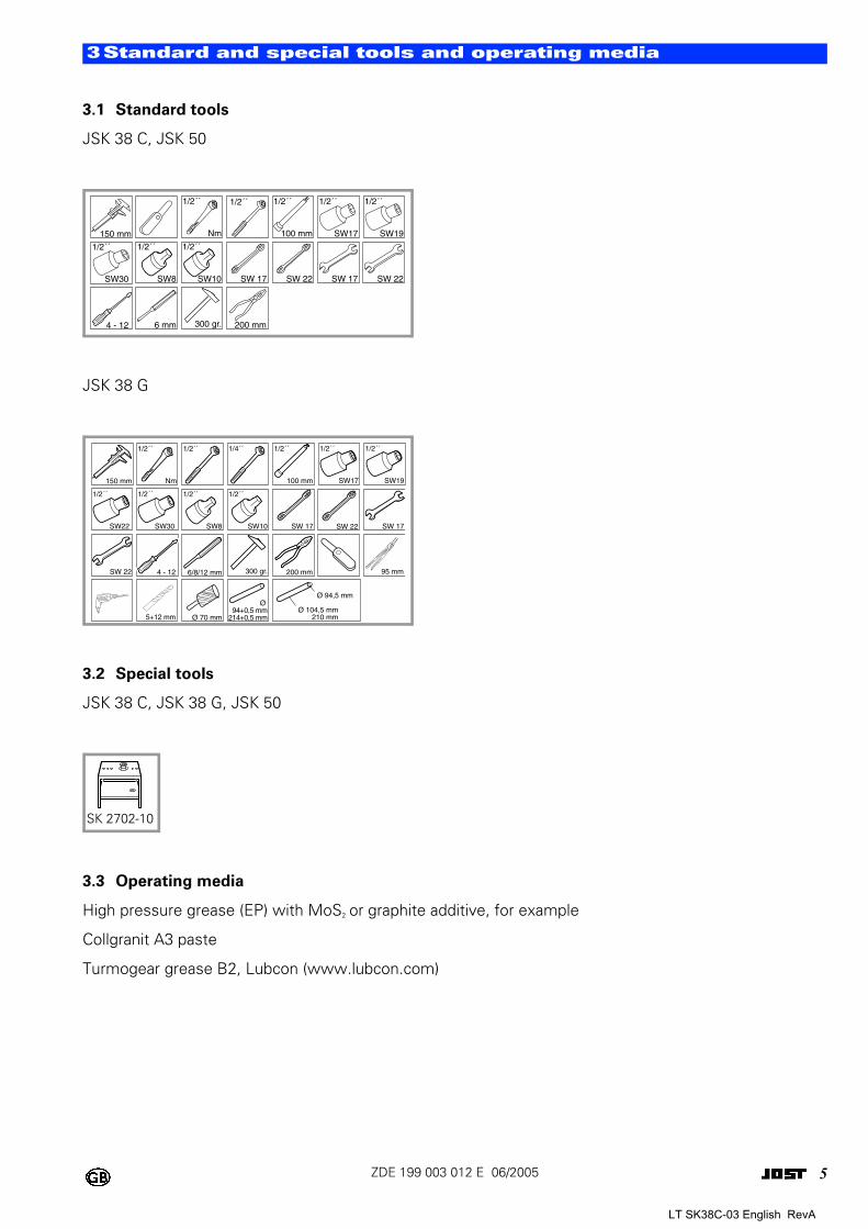
3.1 Standard tools
JSK 38 C, JSK 50
JSK 38 G
3.2 Special tools
JSK 38 C, JSK 38 G, JSK 50
3.3 Operating media
High pressure grease (EP) with MoS2 or graphite additive, for example
Collgranit A3 paste
Turmogear grease B2, Lubcon (www.lubcon.com)
0
0
0
150 mm
1/2´´
100 mm
1/2´´
SW8
1/2´´
SW10
1/2´´
SW19
1/2´´
SW17
1/2´´
SW30 SW 17 SW 22 SW 17 SW 22
6 mm 300 gr. 200 mm4 - 12
1/2´´1/2´´
Nm
150 mm
1/2´´
Nm
1/2´´ 1/4´´ 1/2´´
100 mm
1/2´´
SW8
1/2´´
SW10
1/2´´
SW19
1/2´´
SW17
1/2´´
SW30
1/2´´
SW22 SW 17 SW 22 SW 17
SW 22 6/8/12 mm 300 gr. 200 mm4 - 12 95 mm
5+12 mm
Ø 94+0,5 mm
214+0,5 mmØ 70 mmØ 104,5 mm
210 mm
Ø 94,5 mm
SK 2702-10
LT SK38C-03 English RevA
6ZDE 199 003 012 E 06/2005
4Repair work
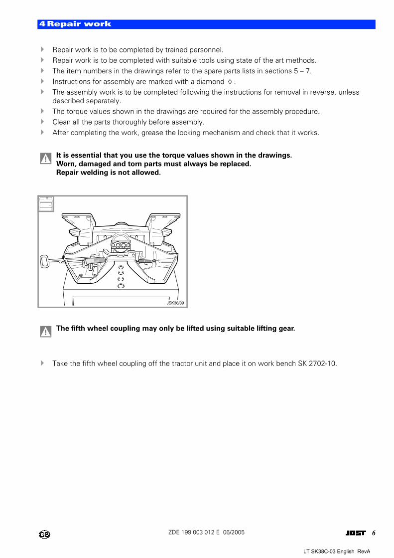
! Repair work is to be completed by trained personnel.! Repair work is to be completed with suitable tools using state of the art methods.! The item numbers in the drawings refer to the spare parts lists in sections 5 – 7.! Instructions for assembly are marked with a diamond .! The assembly work is to be completed following the instructions for removal in reverse, unless
described separately.! The torque values shown in the drawings are required for the assembly procedure.! Clean all the parts thoroughly before assembly.! After completing the work, grease the locking mechanism and check that it works.
! Take the fifth wheel coupling off the tractor unit and place it on work bench SK 2702-10.
! It is essential that you use the torque values shown in the drawings.
Worn, damaged and torn parts must always be replaced.
Repair welding is not allowed.
0
! The fifth wheel coupling may only be lifted using suitable lifting gear.
JSK38/09
LT SK38C-03 English RevA
7ZDE 199 003 012 E 06/2005
4Repair work
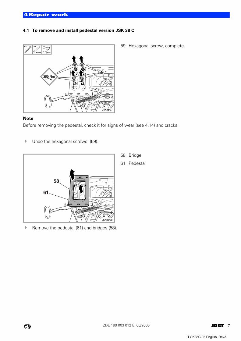
4.1 To remove and install pedestal version JSK 38 C
Note
Before removing the pedestal, check it for signs of wear (see 4.14) and cracks.
! Undo the hexagonal screws (59).
! Remove the pedestal (61) and bridges (58).
0 59 Hexagonal screw, complete
0 58 Bridge
61 Pedestal
1/2´´
59
JSK38/27
350 Nm
1/2´´
100 mm
1/2´´
SW30
61
58
JSK38/28
LT SK38C-03 English RevA
8ZDE 199 003 012 E 06/2005
4Repair work
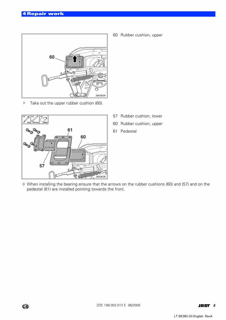
! Take out the upper rubber cushion (60).
When installing the bearing ensure that the arrows on the rubber cushions (60) and (57) and on the pedestal (61) are installed pointing towards the front.
0 60 Rubber cushion, upper
0 57 Rubber cushion, lower
60 Rubber cushion, upper
61 Pedestal
60
JSK38/29
57
61
60
JSK38/30
1/2´´
Nm
1/2´´
100 mm
1/2´´
SW30
LT SK38C-03 English RevA
9ZDE 199 003 012 E 06/2005
4Repair work
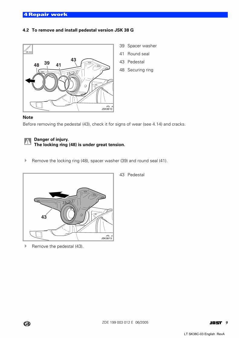
4.2 To remove and install pedestal version JSK 38 G
Note
Before removing the pedestal (43), check it for signs of wear (see 4.14) and cracks.
! Remove the locking ring (48), spacer washer (39) and round seal (41).
! Remove the pedestal (43).
0
39 Spacer washer
41 Round seal
43 Pedestal
48 Securing ring
! Danger of injury.
The locking ring (48) is under great tension.
0
43 Pedestal
95 mm
JSK38/10
43413948
43
JSK38/13
LT SK38C-03 English RevA
10ZDE 199 003 012 E 06/2005
4Repair work
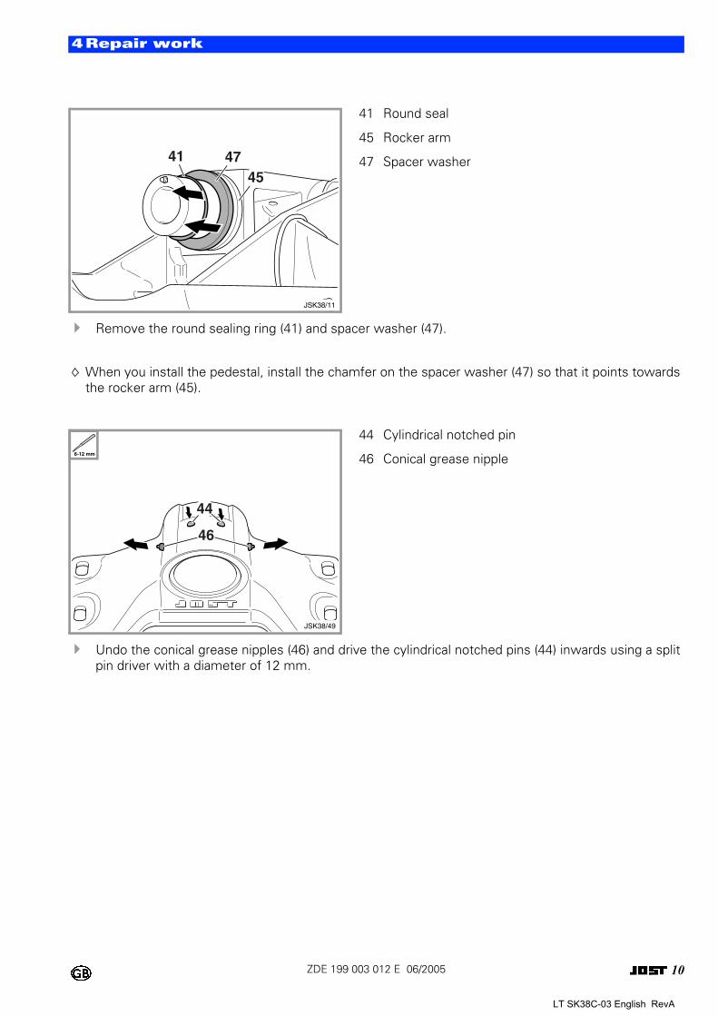
! Remove the round sealing ring (41) and spacer washer (47).
When you install the pedestal, install the chamfer on the spacer washer (47) so that it points towards the rocker arm (45).
! Undo the conical grease nipples (46) and drive the cylindrical notched pins (44) inwards using a split pin driver with a diameter of 12 mm.
0
41 Round seal
45 Rocker arm
47 Spacer washer
0
44 Cylindrical notched pin
46 Conical grease nipple
41 47
JSK38/11
45
6-12 mm
44
46
JSK38/49
LT SK38C-03 English RevA
11ZDE 199 003 012 E 06/2005
4Repair work
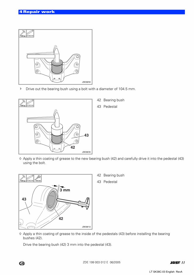
! Drive out the bearing bush using a bolt with a diameter of 104.5 mm.
Apply a thin coating of grease to the new bearing bush (42) and carefully drive it into the pedestal (43) using the bolt.
Apply a thin coating of grease to the inside of the pedestals (43) before installing the bearing bushes (42).
Drive the bearing bush (42) 3 mm into the pedestal (43).
0
0 42 Bearing bush
43 Pedestal
0 42 Bearing bush
43 Pedestal
1500 gr. Ø 104,5 mm
JSK38/50
1500 gr. Ø 104,5 mm
43
42JSK38/35
1500 gr. Ø 104,5 mm 150 mm
3 mm
43
42
JSK38/12
LT SK38C-03 English RevA
12ZDE 199 003 012 E 06/2005
4Repair work
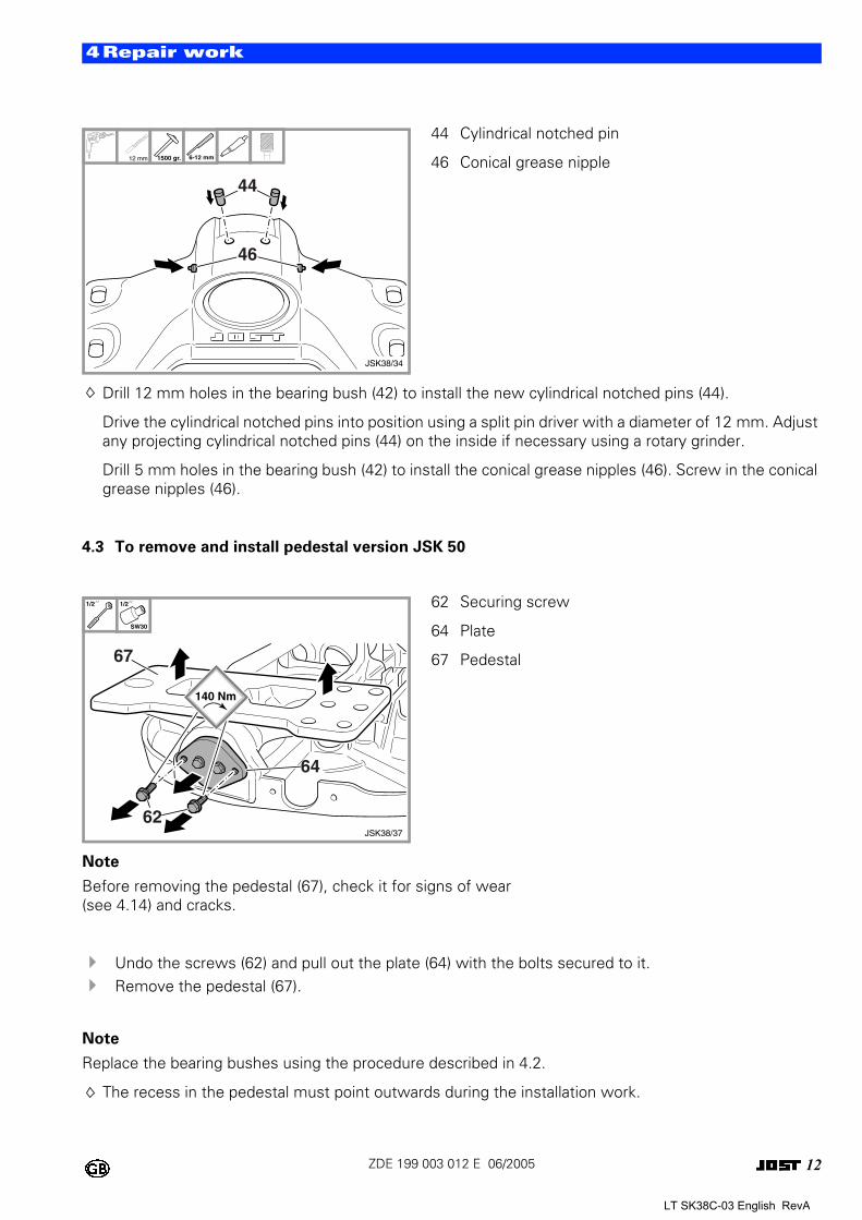
Drill 12 mm holes in the bearing bush (42) to install the new cylindrical notched pins (44).
Drive the cylindrical notched pins into position using a split pin driver with a diameter of 12 mm. Adjust any projecting cylindrical notched pins (44) on the inside if necessary using a rotary grinder.
Drill 5 mm holes in the bearing bush (42) to install the conical grease nipples (46). Screw in the conical grease nipples (46).
4.3 To remove and install pedestal version JSK 50
Note
Before removing the pedestal (67), check it for signs of wear (see 4.14) and cracks.
! Undo the screws (62) and pull out the plate (64) with the bolts secured to it. ! Remove the pedestal (67).
Note
Replace the bearing bushes using the procedure described in 4.2.
The recess in the pedestal must point outwards during the installation work.
0 44 Cylindrical notched pin
46 Conical grease nipple
0 62 Securing screw
64 Plate
67 Pedestal
12 mm 1500 gr.
44
46
JSK38/34
6-12 mm
1/2´´ 1/2´´
SW30
62
64
67
JSK38/37
140 Nm
LT SK38C-03 English RevA
13ZDE 199 003 012 E 06/2005
4Repair work
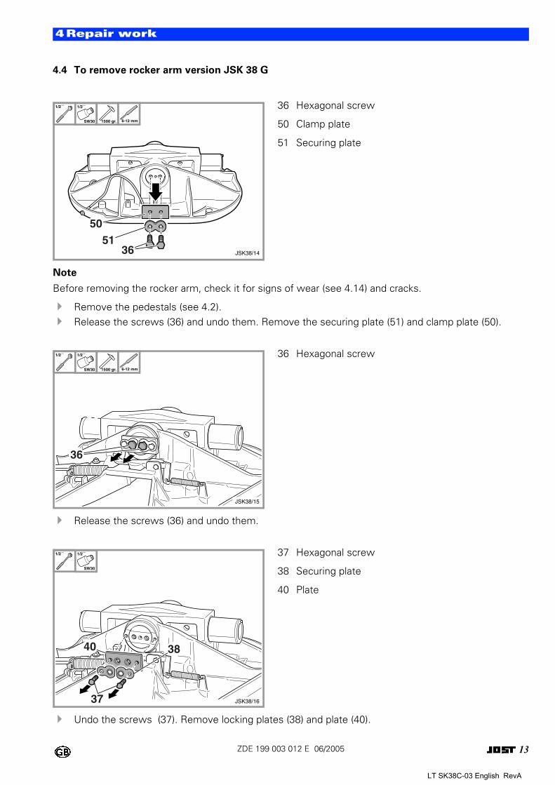
4.4 To remove rocker arm version JSK 38 G
Note
Before removing the rocker arm, check it for signs of wear (see 4.14) and cracks.
! Remove the pedestals (see 4.2). ! Release the screws (36) and undo them. Remove the securing plate (51) and clamp plate (50).
! Release the screws (36) and undo them.
! Undo the screws (37). Remove locking plates (38) and plate (40).
0 36 Hexagonal screw
50 Clamp plate
51 Securing plate
0 36 Hexagonal screw
0 37 Hexagonal screw
38 Securing plate
40 Plate
1/2´´ 1/2´´
SW30 1500 gr. 6-12 mm
5051
36 JSK38/14
1/2´´ 1/2´´
SW30 1500 gr. 6-12 mm
36
JSK38/15
1/2´´ 1/2´´
SW30
40 38
37 JSK38/16
LT SK38C-03 English RevA
14ZDE 199 003 012 E 06/2005
4Repair work
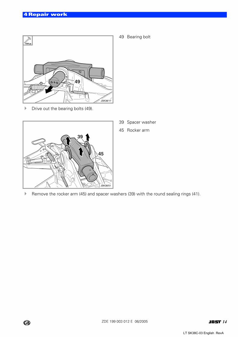
! Drive out the bearing bolts (49).
! Remove the rocker arm (45) and spacer washers (39) with the round sealing rings (41).
0 49 Bearing bolt
0 39 Spacer washer
45 Rocker arm
1500 gr.
49
JSK38/17
39
45
JSK38/51
LT SK38C-03 English RevA
15ZDE 199 003 012 E 06/2005
4Repair work
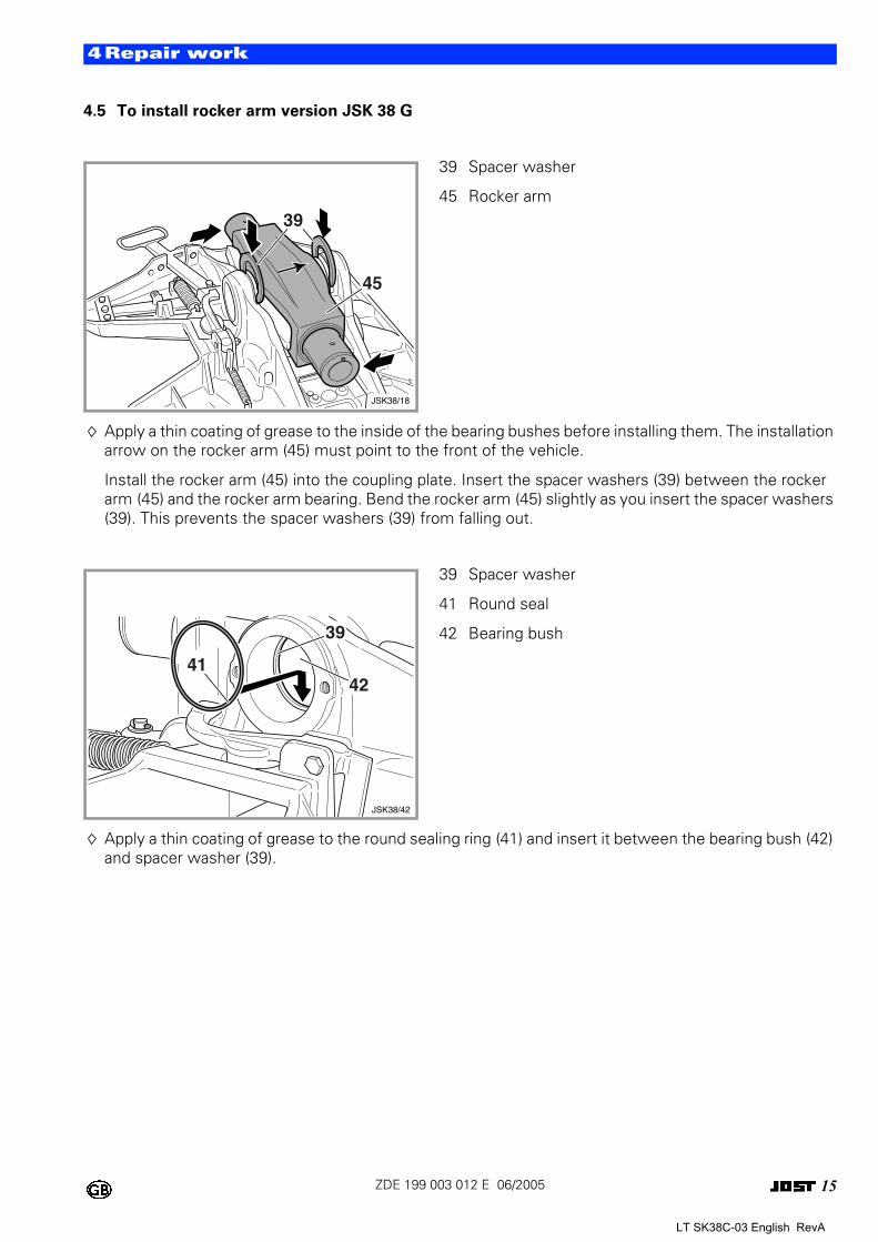
4.5 To install rocker arm version JSK 38 G
Apply a thin coating of grease to the inside of the bearing bushes before installing them. The installation arrow on the rocker arm (45) must point to the front of the vehicle.
Install the rocker arm (45) into the coupling plate. Insert the spacer washers (39) between the rocker arm (45) and the rocker arm bearing. Bend the rocker arm (45) slightly as you insert the spacer washers (39). This prevents the spacer washers (39) from falling out.
Apply a thin coating of grease to the round sealing ring (41) and insert it between the bearing bush (42) and spacer washer (39).
0 39 Spacer washer
45 Rocker arm
0 39 Spacer washer
41 Round seal
42 Bearing bush
39
45
JSK38/18
JSK38/42
42
39
41
LT SK38C-03 English RevA
16ZDE 199 003 012 E 06/2005
4Repair work
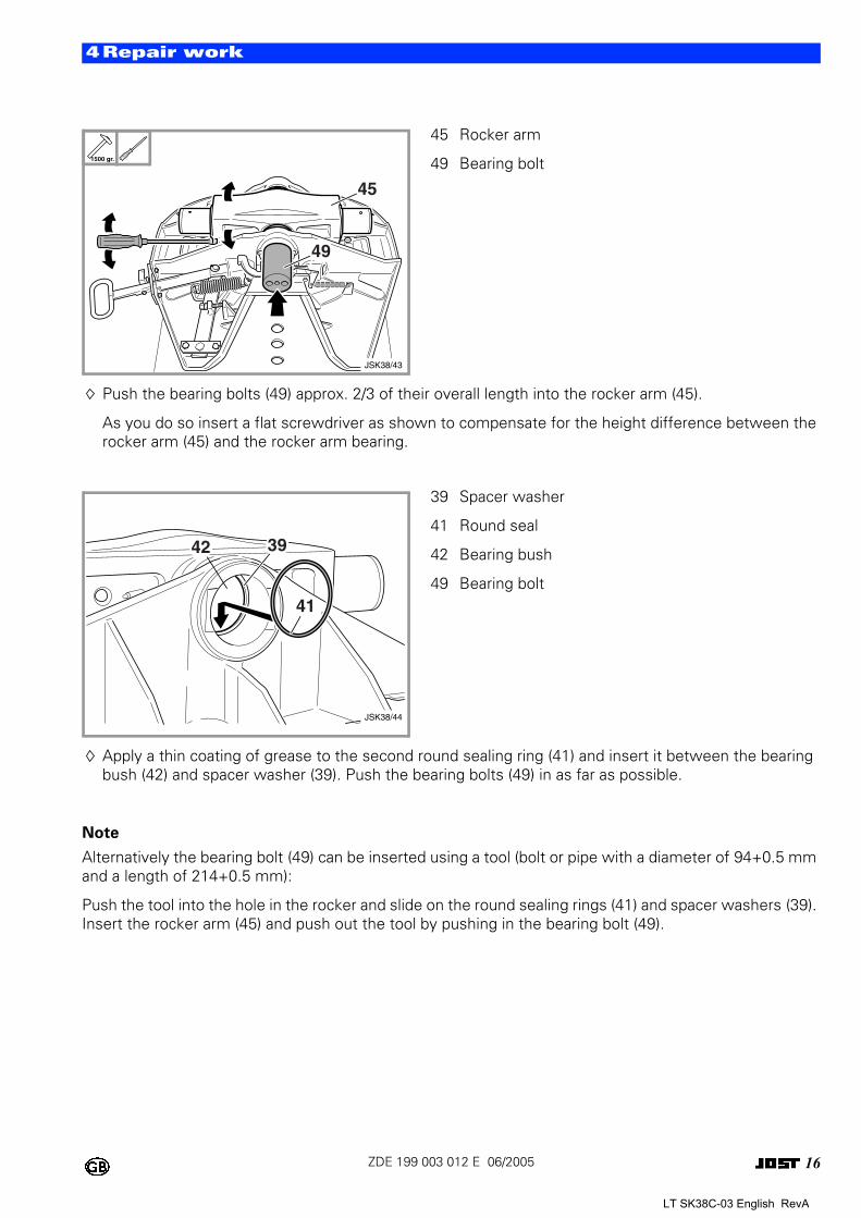
Push the bearing bolts (49) approx. 2/3 of their overall length into the rocker arm (45).
As you do so insert a flat screwdriver as shown to compensate for the height difference between the rocker arm (45) and the rocker arm bearing.
Apply a thin coating of grease to the second round sealing ring (41) and insert it between the bearing bush (42) and spacer washer (39). Push the bearing bolts (49) in as far as possible.
Note
Alternatively the bearing bolt (49) can be inserted using a tool (bolt or pipe with a diameter of 94+0.5 mm and a length of 214+0.5 mm):
Push the tool into the hole in the rocker and slide on the round sealing rings (41) and spacer washers (39). Insert the rocker arm (45) and push out the tool by pushing in the bearing bolt (49).
0 45 Rocker arm
49 Bearing bolt
0 39 Spacer washer
41 Round seal
42 Bearing bush
49 Bearing bolt
1500 gr.
JSK38/43
45
49
JSK38/44
39
41
42
LT SK38C-03 English RevA
17ZDE 199 003 012 E 06/2005
4Repair work
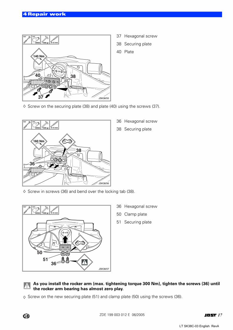
Screw on the securing plate (38) and plate (40) using the screws (37).
Screw in screws (36) and bend over the locking tab (38).
Screw on the new securing plate (51) and clamp plate (50) using the screws (36).
0 37 Hexagonal screw
38 Securing plate
40 Plate
0 36 Hexagonal screw
38 Securing plate
0 36 Hexagonal screw
50 Clamp plate
51 Securing plate
! As you install the rocker arm (max. tightening torque 300 Nm), tighten the screws (36) until
the rocker arm bearing has almost zero play.
1/2´´ 1/2´´
SW30 1500 gr. 6-12 mm
140 Nm
40 38
37 JSK38/55
1/2´´ 1/2´´
SW30 1500 gr. 6-12 mm
36
JSK38/56
160 Nm
38
1/2´´ 1/2´´
SW30 1500 gr. 6-12 mm
5051
36JSK38/57
LT SK38C-03 English RevA
18ZDE 199 003 012 E 06/2005
4Repair work
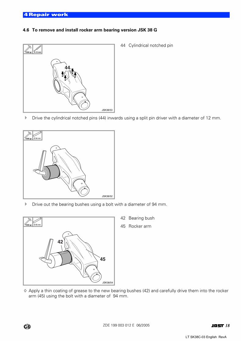
4.6 To remove and install rocker arm bearing version JSK 38 G
! Drive the cylindrical notched pins (44) inwards using a split pin driver with a diameter of 12 mm.
! Drive out the bearing bushes using a bolt with a diameter of 94 mm.
Apply a thin coating of grease to the new bearing bushes (42) and carefully drive them into the rocker arm (45) using the bolt with a diameter of 94 mm.
0 44 Cylindrical notched pin
0
0 42 Bearing bush
45 Rocker arm
1500 gr. 6-12 mm
JSK38/53
44
1500 gr. Ø 94 mm
JSK38/52
1500 gr. Ø 94 mm
JSK38/54
45
42
LT SK38C-03 English RevA
19ZDE 199 003 012 E 06/2005
4Repair work
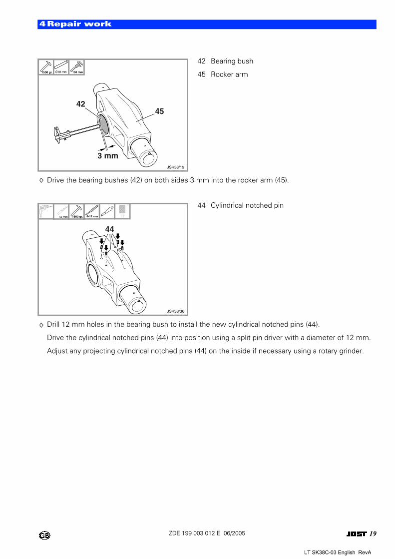
Drive the bearing bushes (42) on both sides 3 mm into the rocker arm (45).
Drill 12 mm holes in the bearing bush to install the new cylindrical notched pins (44).
Drive the cylindrical notched pins (44) into position using a split pin driver with a diameter of 12 mm.
Adjust any projecting cylindrical notched pins (44) on the inside if necessary using a rotary grinder.
0 42 Bearing bush
45 Rocker arm
0 44 Cylindrical notched pin
1500 gr. Ø 94 mm 150 mm
JSK38/19
3 mm
4245
12 mm 1500 gr. 6-12 mm
JSK38/36
44
LT SK38C-03 English RevA
20ZDE 199 003 012 E 06/2005
4Repair work
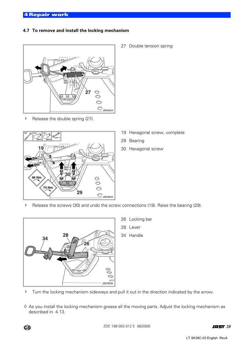
4.7 To remove and install the locking mechanism
! Release the double spring (27).
! Release the screws (30) and undo the screw connections (19). Raise the bearing (29).
! Turn the locking mechanism sideways and pull it out in the direction indicated by the arrow.
As you install the locking mechanism grease all the moving parts. Adjust the locking mechanism as described in 4.13.
0 27 Double tension spring
0 19 Hexagonal screw, complete
29 Bearing
30 Hexagonal screw
0 26 Locking bar
28 Lever
34 Handle
JSK38/24
27
1/2´´ 1/2´´
SW17
1/2´´
SW19SW 17
JSK38/25
19
30
29
46 Nm
74 Nm
JSK38/26
26
2834
LT SK38C-03 English RevA
21ZDE 199 003 012 E 06/2005
4Repair work
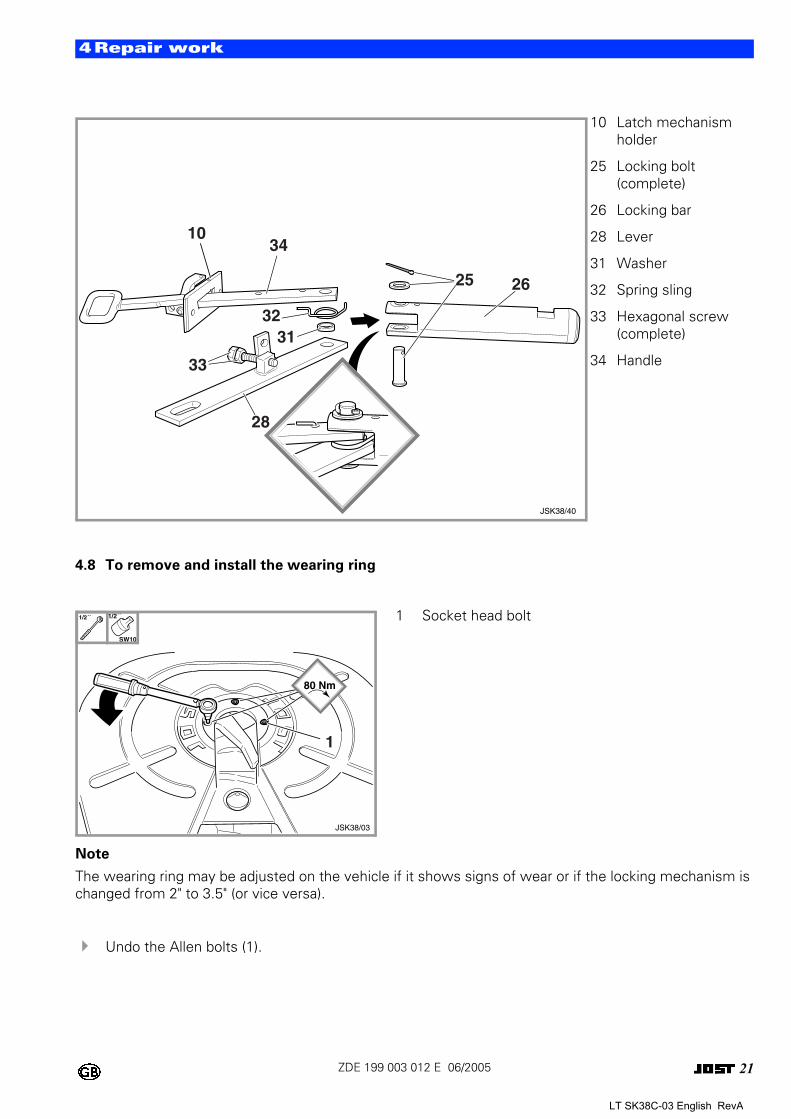
4.8 To remove and install the wearing ring
Note
The wearing ring may be adjusted on the vehicle if it shows signs of wear or if the locking mechanism is changed from 2" to 3.5" (or vice versa).
! Undo the Allen bolts (1).
010 Latch mechanism holder
25 Locking bolt (complete)
26 Locking bar
28 Lever
31 Washer
32 Spring sling
33 Hexagonal screw (complete)
34 Handle
0 1 Socket head bolt
JSK38/40
26
28
3132
10
33
34
25
1/2´´ 1/2´´
SW10
80 Nm
1
JSK38/03
LT SK38C-03 English RevA
22ZDE 199 003 012 E 06/2005
4Repair work
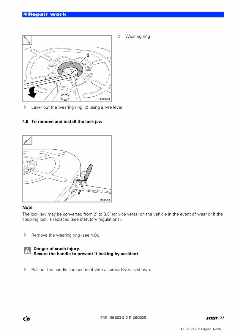
! Lever out the wearing ring (2) using a tyre lever.
4.9 To remove and install the lock jaw
Note
The lock jaw may be converted from 2" to 3.5" (or vice versa) on the vehicle in the event of wear or if the coupling lock is replaced (see statutory regulations).
! Remove the wearing ring (see 4.8).
! Pull out the handle and secure it with a screwdriver as shown.
0 2 Wearing ring
0
! Danger of crush injury.
Secure the handle to prevent it locking by accident.
2
JSK38/04
JSK38/02
LT SK38C-03 English RevA
23ZDE 199 003 012 E 06/2005
4Repair work
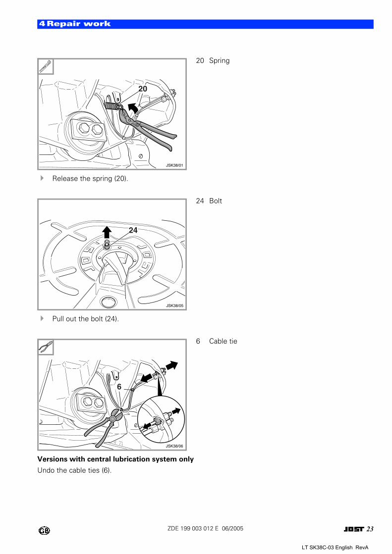
! Release the spring (20).
! Pull out the bolt (24).
Versions with central lubrication system only
Undo the cable ties (6).
0 20 Spring
0 24 Bolt
0 6 Cable tie
JSK38/01
20
24
JSK38/05
JSK38/06
6
LT SK38C-03 English RevA
24ZDE 199 003 012 E 06/2005
4Repair work
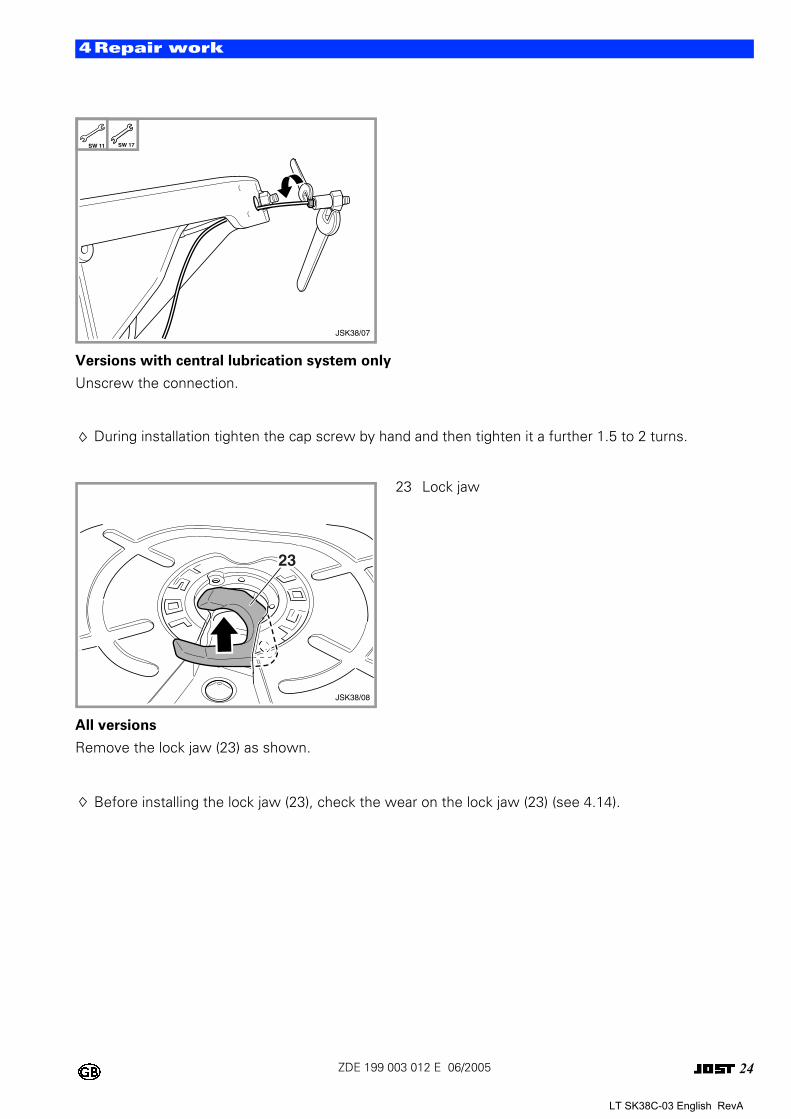
Versions with central lubrication system only
Unscrew the connection.
During installation tighten the cap screw by hand and then tighten it a further 1.5 to 2 turns.
All versions
Remove the lock jaw (23) as shown.
Before installing the lock jaw (23), check the wear on the lock jaw (23) (see 4.14).
0
0 23 Lock jaw
SW 11 SW 17
JSK38/07
23
JSK38/08
LT SK38C-03 English RevA
25ZDE 199 003 012 E 06/2005
4Repair work
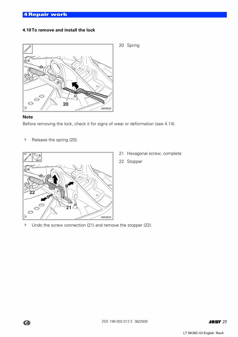
4.10To remove and install the lock
Note
Before removing the lock, check it for signs of wear or deformation (see 4.14).
! Release the spring (20).
! Undo the screw connection (21) and remove the stopper (22).
0 20 Spring
0 21 Hexagonal screw, complete
22 Stopper
20JSK38/22
1/2´´ 1/2´´
SW17
21
JSK38/23
22
LT SK38C-03 English RevA
26ZDE 199 003 012 E 06/2005
4Repair work
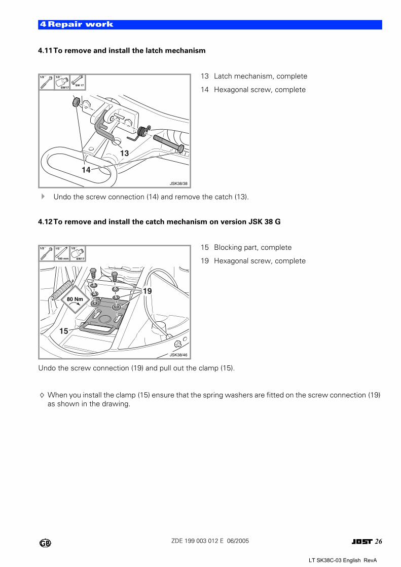
4.11To remove and install the latch mechanism
! Undo the screw connection (14) and remove the catch (13).
4.12To remove and install the catch mechanism on version JSK 38 G
Undo the screw connection (19) and pull out the clamp (15).
When you install the clamp (15) ensure that the spring washers are fitted on the screw connection (19) as shown in the drawing.
0 13 Latch mechanism, complete
14 Hexagonal screw, complete
0 15 Blocking part, complete
19 Hexagonal screw, complete
1/2´´ 1/2´´
SW17SW 17
JSK38/38
14
13
1/2´´ 1/2´´
100 mm
1/2´´
SW17
JSK38/46
15
1980 Nm
LT SK38C-03 English RevA
27ZDE 199 003 012 E 06/2005
4Repair work
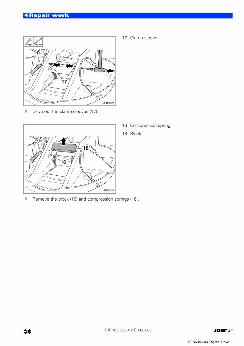
! Drive out the clamp sleeves (17).
! Remove the block (18) and compression springs (16).
0 17 Clamp sleeve
0 16 Compression spring
18 Block
1500 gr. 6-12 mm
17
JSK38/20
16
JSK38/21
18
LT SK38C-03 English RevA
28ZDE 199 003 012 E 06/2005
4Repair work
4.13To adjust the locking mechanism
Note
The king pin should have play of at least 0.3 mm in the locking mechanism.
Adjust the locking mechanism with a correctly sized king pin that has a maximum overall wear limit of 0.25 mm.
Close the locking mechanism and undo the lock nut on the screw connection (33). Undo the screw connection (33) until it is no longer in contact with the stop.
Move the locking bar to its limit position by tapping the handle (34) gently in the locking direction and recouple the trailer.
Tighten the screw connection (33) until the handle (34) starts to move.
From this point tighten the screw connection (33) approx. one more turn (one turn results in play of 0.3 mm).
Tighten the lock nut on the screw connection (33).
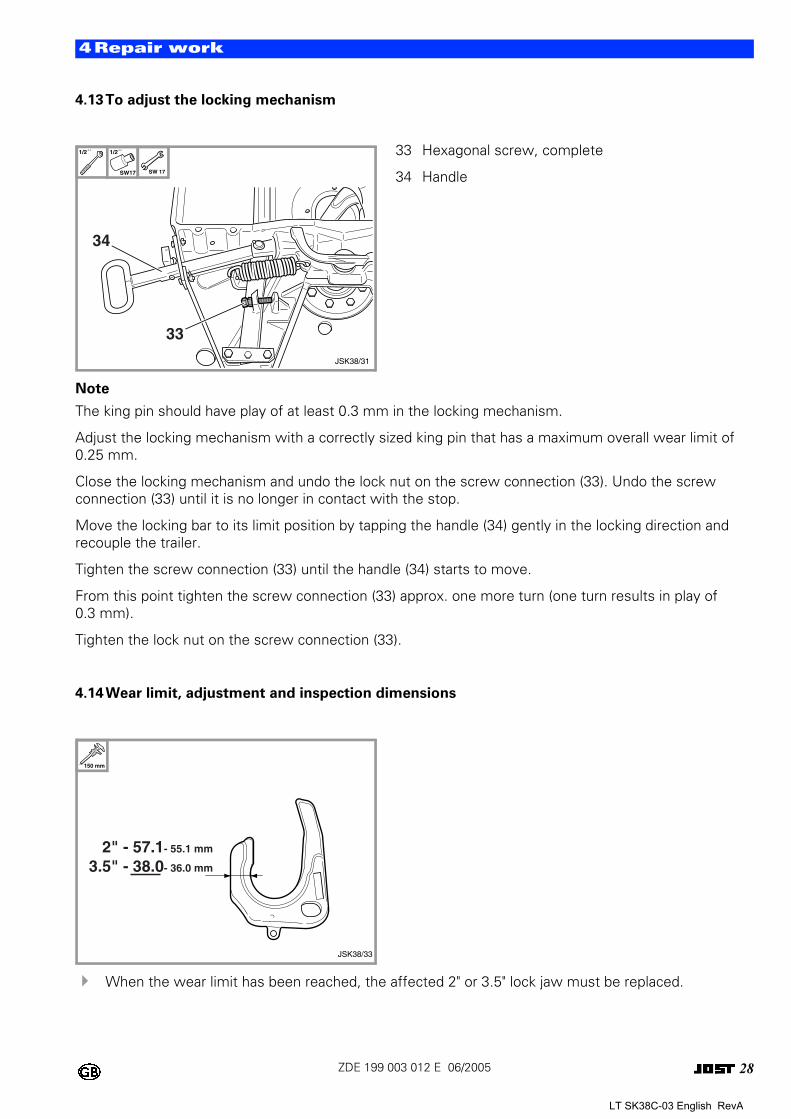
4.14Wear limit, adjustment and inspection dimensions
! When the wear limit has been reached, the affected 2" or 3.5" lock jaw must be replaced.
0 33 Hexagonal screw, complete
34 Handle
0
1/2´´ 1/2´´
SW17 SW 17
33
JSK38/31
34
150 mm
JSK38/33
2" - 57.1- 55.1 mm
3.5" - 38.0- 36.0 mm
LT SK38C-03 English RevA
29ZDE 199 003 012 E 06/2005
4Repair work
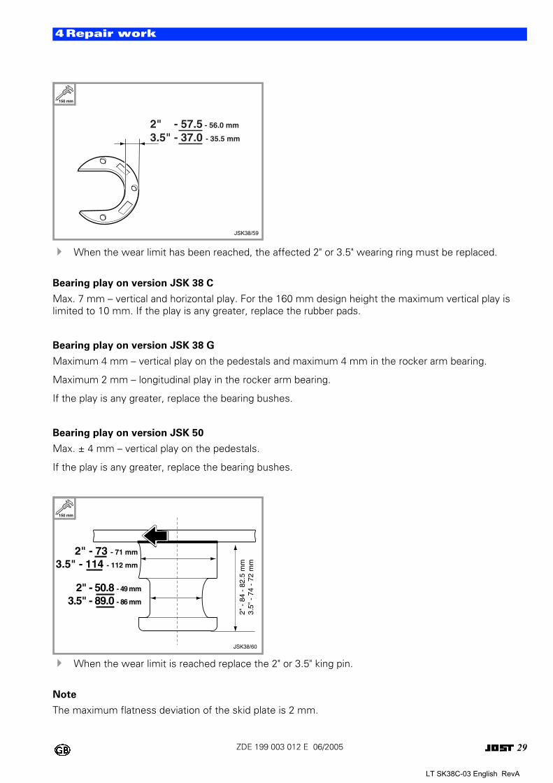
! When the wear limit has been reached, the affected 2" or 3.5" wearing ring must be replaced.
Bearing play on version JSK 38 C
Max. 7 mm – vertical and horizontal play. For the 160 mm design height the maximum vertical play is limited to 10 mm. If the play is any greater, replace the rubber pads.
Bearing play on version JSK 38 G
Maximum 4 mm – vertical play on the pedestals and maximum 4 mm in the rocker arm bearing.
Maximum 2 mm – longitudinal play in the rocker arm bearing.
If the play is any greater, replace the bearing bushes.
Bearing play on version JSK 50
Max. ± 4 mm – vertical play on the pedestals.
If the play is any greater, replace the bearing bushes.
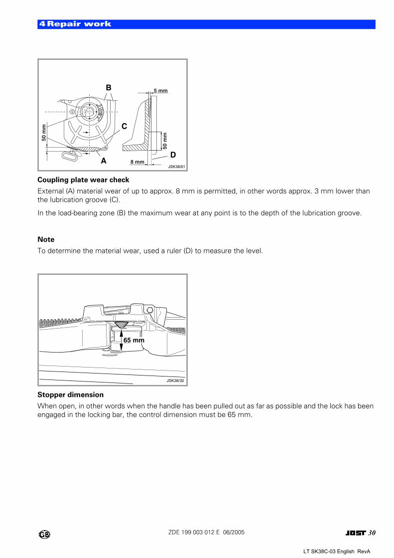
! When the wear limit is reached replace the 2" or 3.5" king pin.
Note
The maximum flatness deviation of the skid plate is 2 mm.
0
0
150 mm
JSK38/59
2" - 57.5 - 56.0 mm
3.5" - 37.0 - 35.5 mm
2" - 73 - 71 mm
3.5" - 114 - 112 mm
2" -
84
- 82
.5 m
m3.
5" -
74
- 72
mm
JSK38/60
2" - 50.8 - 49 mm
3.5" - 89.0 - 86 mm
150 mm
LT SK38C-03 English RevA
30ZDE 199 003 012 E 06/2005
4Repair work
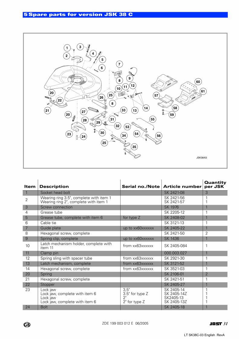
Coupling plate wear check
External (A) material wear of up to approx. 8 mm is permitted, in other words approx. 3 mm lower than the lubrication groove (C).
In the load-bearing zone (B) the maximum wear at any point is to the depth of the lubrication groove.
Note
To determine the material wear, used a ruler (D) to measure the level.
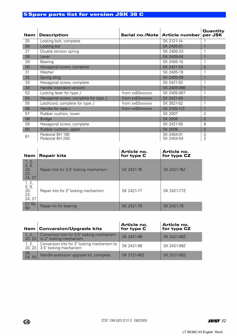
Stopper dimension
When open, in other words when the handle has been pulled out as far as possible and the lock has been engaged in the locking bar, the control dimension must be 65 mm.
0
0
8 mm50
mm
5 mm
50 m
m
JSK38/61A
C
B
D
65 mm
JSK38/32
LT SK38C-03 English RevA
31ZDE 199 003 012 E 06/2005
5Spare parts for version JSK 38 C
Item Description Serial no./Note Article numberQuantityper JSK
1 Socket head bolt SK 2421-08 3
2 Wearing ring 3.5", complete with item 1Wearing ring 2", complete with item 1
SK 2421-56SK 2421-57
11
3 Screw connection SK 1976 14 Grease tube SK 2205-12 15 Grease tube, complete with item 6 for type Z SK 2408-02 16 Cable tie SK 3121-13 17 Guide plate up to xx60xxxxxx SK 2405-22 18 Hexagonal screw, complete SK 2421-50 29 Spring clip, complete up to xx60xxxxxx SK 1436 1
10 Latch mechanism holder, complete with item 11 from xx63xxxxxx SK 2405-084 1
11 Clamp pin 000.003.027 112 Spring sling with spacer tube from xx63xxxxxx SK 2921-30 113 Latch mechanism, complete from xx63xxxxxx SK 3121-52 114 Hexagonal screw, complete from xx63xxxxxx SK 3521-03 120 Spring SK 2106-01 221 Hexagonal screw, complete SK 2421-51 122 Stopper SK 2405-27 123 Lock jaw
Lock jaw, complete with item 6Lock jawLock jaw, complete with item 6
3,5"3.5" for type Z2"2" for type Z
SK 2405-14SK 2405-14ZSK2405-13SK 2405-13Z
1111
24 Bolt SK 2405-18 1
2
1 3
4
67
11
2625
3359
57
55
58
56
53
5434
3525
12
27
2324
30
2928
21
20
20
148
60
61
13
22
8
31
32
9
5
10
JSK38/63
LT SK38C-03 English RevA
32ZDE 199 003 012 E 06/2005
5Spare parts list for version JSK 38 C
25 Locking bolt, complete SK 2121-14 126 Locking bar SK 2405-01 127 Double tension spring SK 2405-23 128 Lever SK 2405-04 129 Bearing SK 2405-15 130 Hexagonal screw, complete SK 2421-53 231 Washer SK 2405-19 132 Spring sling SK 2405-09 133 Hexagonal screw, complete SK 2421-52 134 Handle (standard version) SK 2405-066 153 Locking lever for type J from xx63xxxxxx SK 2405-067 154 Hexagonal screw, complete for type J from xx63xxxxxx SK 2421-50 155 Latchcord, complete for type J from xx63xxxxxx SK 3521-02 156 Handle for type J from xx63xxxxxx SK 3105-113 157 Rubber cushion, lower SK 2007 258 Bridge SK 2005 259 Hexagonal screw, complete SK 2421-55 860 Rubber cushion, upper SK 2006 2
61 Pedestal BH 190Pedestal BH 250
SK 2404-01SK 2404-04
22
Item Repair kitsArticle no. for type C
Article no. for type CZ
1, 2, 5, 9, 20, 23, 24, 27
Repair kits for 3.5" locking mechanism SK 2421-76 SK 2421-76Z
1, 2, 5, 9, 20, 23, 24, 27
Repair kits for 2" locking mechanism SK 2421-77 SK 2421-77Z
57, 58, 60 Repair kit for bearing SK 2421-78 SK 2421-78
Item Conversion/Upgrade kitsArticle no. for type C
Article no. for type CZ
1, 2, 20, 23
Conversion kits for 3.5" locking mechanism to 2" locking mechanism SK 2421-98 SK 2421-98Z
1, 2, 20, 23
Conversion kits for 2" locking mechanism to3.5" locking mechanism SK 2421-99 SK 2421-99Z
35, 54, 55 Handle extension upgrade kit, complete SK 3121-063 SK 3121-063
Item Description Serial no./Note Article numberQuantityper JSK
LT SK38C-03 English RevA
33ZDE 199 003 012 E 06/2005
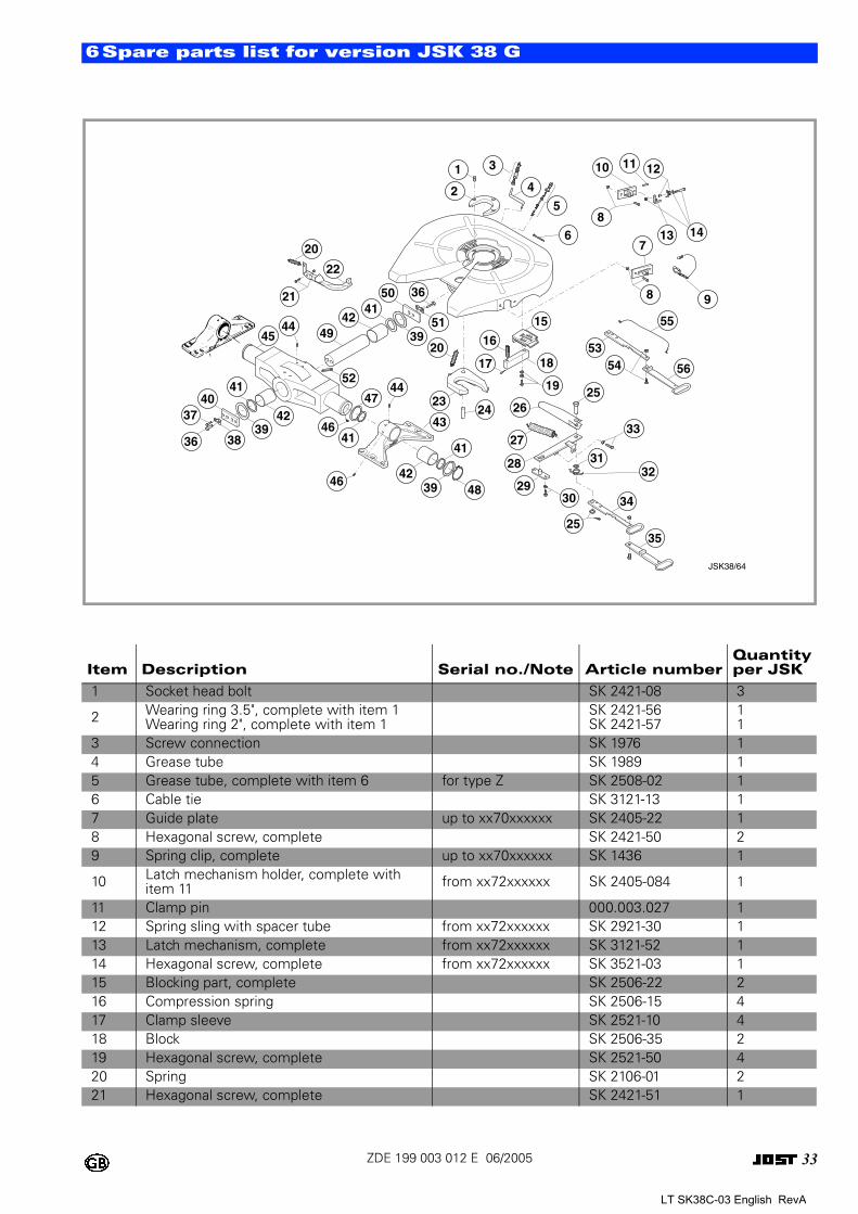
6Spare parts list for version JSK 38 G
Item Description Serial no./Note Article numberQuantityper JSK
1 Socket head bolt SK 2421-08 3
2 Wearing ring 3.5", complete with item 1Wearing ring 2", complete with item 1
SK 2421-56SK 2421-57
11
3 Screw connection SK 1976 14 Grease tube SK 1989 15 Grease tube, complete with item 6 for type Z SK 2508-02 16 Cable tie SK 3121-13 17 Guide plate up to xx70xxxxxx SK 2405-22 18 Hexagonal screw, complete SK 2421-50 29 Spring clip, complete up to xx70xxxxxx SK 1436 1
10 Latch mechanism holder, complete with item 11 from xx72xxxxxx SK 2405-084 1
11 Clamp pin 000.003.027 112 Spring sling with spacer tube from xx72xxxxxx SK 2921-30 113 Latch mechanism, complete from xx72xxxxxx SK 3121-52 114 Hexagonal screw, complete from xx72xxxxxx SK 3521-03 115 Blocking part, complete SK 2506-22 216 Compression spring SK 2506-15 417 Clamp sleeve SK 2521-10 418 Block SK 2506-35 219 Hexagonal screw, complete SK 2521-50 420 Spring SK 2106-01 221 Hexagonal screw, complete SK 2421-51 1
JSK38/64
121110
148
137
98
55
56
5354
25
33
32
34
3525
30
3127
26
19
18
15
16
1720
2324
28
29
41
483942
44
43
46
41
47
46
6
5
4
31
2
20
22
21 36
51
50
4441
3949
52
4239
4140
37
3836
45
42
LT SK38C-03 English RevA
34ZDE 199 003 012 E 06/2005
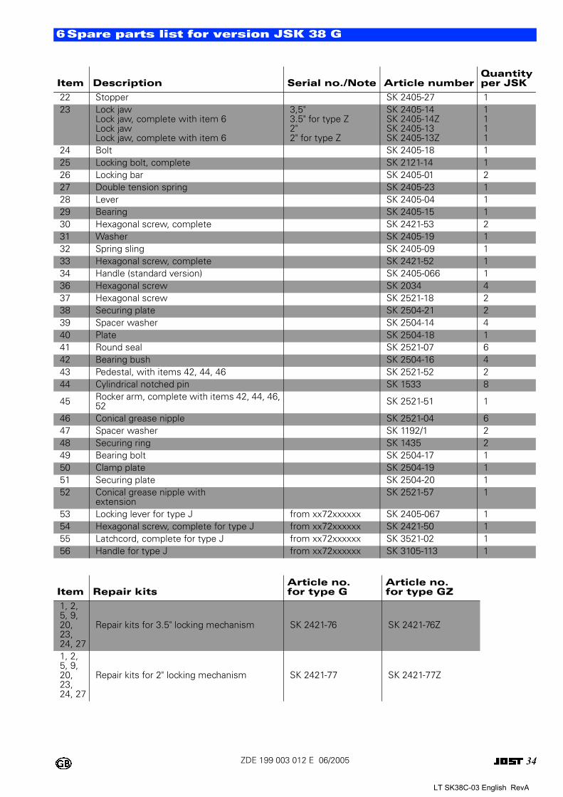
6Spare parts list for version JSK 38 G
22 Stopper SK 2405-27 123 Lock jaw
Lock jaw, complete with item 6Lock jawLock jaw, complete with item 6
3,5"3.5" for type Z2"2" for type Z
SK 2405-14SK 2405-14ZSK 2405-13SK 2405-13Z
1111
24 Bolt SK 2405-18 125 Locking bolt, complete SK 2121-14 126 Locking bar SK 2405-01 227 Double tension spring SK 2405-23 128 Lever SK 2405-04 129 Bearing SK 2405-15 130 Hexagonal screw, complete SK 2421-53 231 Washer SK 2405-19 132 Spring sling SK 2405-09 133 Hexagonal screw, complete SK 2421-52 134 Handle (standard version) SK 2405-066 136 Hexagonal screw SK 2034 437 Hexagonal screw SK 2521-18 238 Securing plate SK 2504-21 239 Spacer washer SK 2504-14 440 Plate SK 2504-18 141 Round seal SK 2521-07 642 Bearing bush SK 2504-16 443 Pedestal, with items 42, 44, 46 SK 2521-52 244 Cylindrical notched pin SK 1533 8
45 Rocker arm, complete with items 42, 44, 46, 52 SK 2521-51 1
46 Conical grease nipple SK 2521-04 647 Spacer washer SK 1192/1 248 Securing ring SK 1435 249 Bearing bolt SK 2504-17 150 Clamp plate SK 2504-19 151 Securing plate SK 2504-20 152 Conical grease nipple with
extensionSK 2521-57 1
53 Locking lever for type J from xx72xxxxxx SK 2405-067 154 Hexagonal screw, complete for type J from xx72xxxxxx SK 2421-50 155 Latchcord, complete for type J from xx72xxxxxx SK 3521-02 156 Handle for type J from xx72xxxxxx SK 3105-113 1
Item Repair kitsArticle no. for type G
Article no. for type GZ
1, 2, 5, 9, 20, 23, 24, 27
Repair kits for 3.5" locking mechanism SK 2421-76 SK 2421-76Z
1, 2, 5, 9, 20, 23, 24, 27
Repair kits for 2" locking mechanism SK 2421-77 SK 2421-77Z
Item Description Serial no./Note Article numberQuantityper JSK
LT SK38C-03 English RevA
35ZDE 199 003 012 E 06/2005
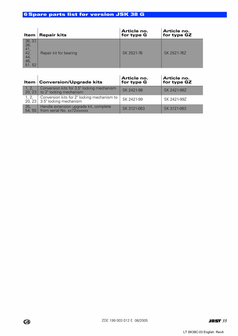
6Spare parts list for version JSK 38 G
36, 37, 38, 41, 42, 44, 46, 51, 52
Repair kit for bearing SK 2521-76 SK 2521-76Z
Item Conversion/Upgrade kitsArticle no. for type G
Article no. for type GZ
1, 2, 20, 23
Conversion kits for 3.5" locking mechanism to 2" locking mechanism SK 2421-98 SK 2421-98Z
1, 2, 20, 23
Conversion kits for 2" locking mechanism to 3.5" locking mechanism SK 2421-99 SK 2421-99Z
35, 54, 55
Handle extension upgrade kit, complete from serial No. xx72xxxxxx SK 3121-063 SK 3121-063
Item Repair kitsArticle no. for type G
Article no. for type GZ
LT SK38C-03 English RevA
36ZDE 199 003 012 E 06/2005
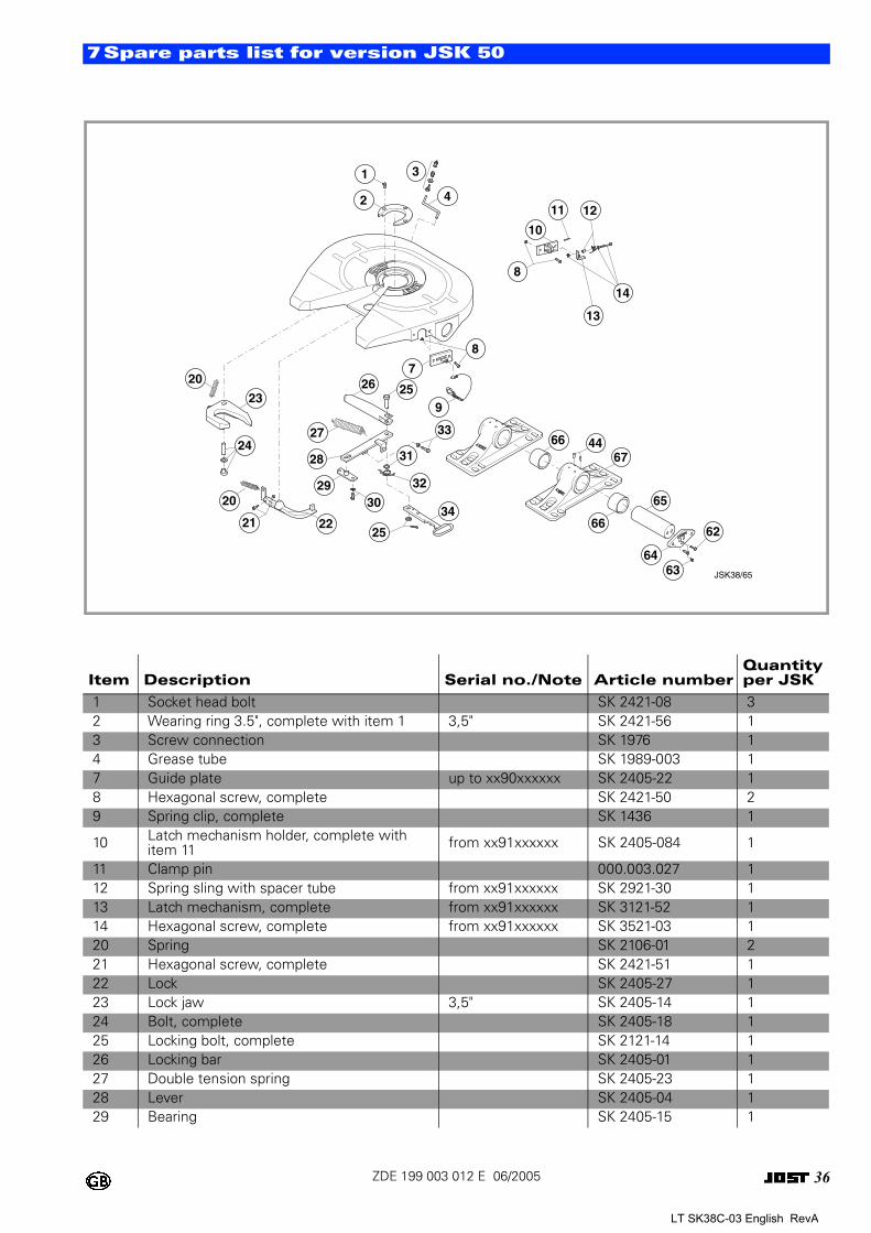
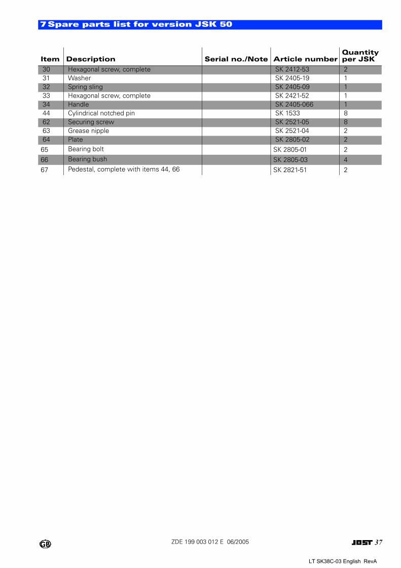
7Spare parts list for version JSK 50
Item Description Serial no./Note Article numberQuantityper JSK
1 Socket head bolt SK 2421-08 32 Wearing ring 3.5", complete with item 1 3,5" SK 2421-56 13 Screw connection SK 1976 14 Grease tube SK 1989-003 17 Guide plate up to xx90xxxxxx SK 2405-22 18 Hexagonal screw, complete SK 2421-50 29 Spring clip, complete SK 1436 1
10 Latch mechanism holder, complete with item 11 from xx91xxxxxx SK 2405-084 1
11 Clamp pin 000.003.027 112 Spring sling with spacer tube from xx91xxxxxx SK 2921-30 113 Latch mechanism, complete from xx91xxxxxx SK 3121-52 114 Hexagonal screw, complete from xx91xxxxxx SK 3521-03 120 Spring SK 2106-01 221 Hexagonal screw, complete SK 2421-51 122 Lock SK 2405-27 123 Lock jaw 3,5" SK 2405-14 124 Bolt, complete SK 2405-18 125 Locking bolt, complete SK 2121-14 126 Locking bar SK 2405-01 127 Double tension spring SK 2405-23 128 Lever SK 2405-04 129 Bearing SK 2405-15 1
207
26 259
33
23
24
20
31
21 2234
3029
27
28
32
25
8
4
66 4467
66
8
65
14
64
10
62
12
63
11
13
1 3
2
JSK38/65
LT SK38C-03 English RevA
37ZDE 199 003 012 E 06/2005
7Spare parts list for version JSK 50
30 Hexagonal screw, complete SK 2412-53 231 Washer SK 2405-19 132 Spring sling SK 2405-09 133 Hexagonal screw, complete SK 2421-52 134 Handle SK 2405-066 144 Cylindrical notched pin SK 1533 862 Securing screw SK 2521-05 863 Grease nipple SK 2521-04 264 Plate SK 2805-02 2
65 Bearing bolt SK 2805-01 2
66 Bearing bush SK 2805-03 467 Pedestal, complete with items 44, 66 SK 2821-51 2
Item Description Serial no./Note Article numberQuantityper JSK
LT SK38C-03 English RevA
38ZDE 199 003 012 E 06/2005
8Waste disposal instructions
These parts fitted to the fith wheel coupling are made of valuable raw materials that can be recycled.
These materials can be separated into plastic / rubber and metallic materials.
The plastic / rubber materials are marked in compliance with VDA Recommendation 260. Before disposal, any oil or grease residue is to be cleaned off the parts, where necessary.
LT SK38C-03 English RevA