repair manual for jsk 37 fi fth-wheel coupling - …€¦ · repair manual for jsk 37 fi...
TRANSCRIPT
Repair manual for
JSK 37 fi fth-wheel coupling
3ZDE 199 002 108 04/2012
Foreword Table of contents
Fifth wheel couplings are vehicle connecting parts that must comply with very high safety require-ments and must also undergo design approval tests.
This repair manual is designed to act as a guide to completing repair work on our fifth wheel couplings.
It is essential that you use JOST spare parts. Modi-fications of any kind will render both the warranty and the type approval void.
Instructions for the operation and installation of the fifth wheel couplings and their permitted load data are provided in separate documents.
1 Safety instructions 4
2 Troubleshooting 5
3 Standard and special tools an auxiliary materials 63.1 Standard tools 63.2 Special tools 63.3 Auxiliary materials 6
4 Repair work 74.1 To remove and install the version C
bearing 74.2 To remove and attach the version E
pedestal 84.3 To remove and install the version E
bearing 84.4 Overview of the locking mechanism 94.5 To remove and install the locking
mechanism 94.6 To remove and install the safety latch 114.7 To remove and install the top plate
liners (W version only) 114.8 To remove and install the lock jaw/
on the vehicle 114.9 To check for wear/wearlimits 134.10 Function test 154.11 To set the locking mechanism 16
5 Spare parts for version JSK37C/CZ 17
6 Spare parts for version JSK37E 18
7 Spare parts for version JSK37CW/EW 19
8 Disposal instructions 20
4 ZDE 199 002 108 04/2012
1 Safety instructions
The relevant safety regulations in your country (for example Health & Safety at Work) apply for working with fifth wheel couplings and vehicles.
The relevant safety instructions included in the vehicle and semi-trailer's operating instructions must also be complied with.
5ZDE 199 002 108 04/2012
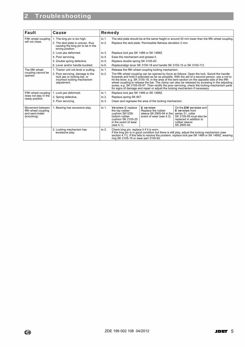
2 Troubleshooting
0
Fault Cause RemedyFifth wheel coupling will not close.
1. The king pin is too high.
2. The skid plate is uneven, thus causing the king pin to be in the wrong position.
3. Lock jaw deformed.
4. Poor servicing.
5. Double spring defective.
6. Lever and/or handle buckled.
to 1. The skid plate should be at the same height or around 50 mm lower than the fifth wheel coupling.
to 2. Replace the skid plate. Permissible flatness deviation 2 mm.
to 3. Replace lock jaw SK 1489 or SK 1489Z.
to 4. Ease the mechanism and grease it.
to 5. Replace double spring SK 3105-20.
to 6. Replace/align lever SK 3105-18 and handle SK 3105-15 or SK 3105-113
The fifth wheel coupling cannot be opened.
1. Tractor unit not level or pulling.
2. Poor servicing, damage to the lock jaw or locking bar, or incorrect locking mechanism adjustment.
to 1. Release the fifth wheel coupling locking mechanism.
to 2. The fifth wheel coupling can be opened by force as follows: Open the lock. Swivel the handle forwards and hold it extended as far as possible. With the aid of a second person, use a rod to hit the lever, e.g. SK 3105-18, in the area of the bent section on the opposite side of the fifth wheel coupling to release the bar. The clamp can also be released by screwing in the adjusting screw, e.g. SK 3105-05-97. Then rectify the poor servicing, check the locking mechanism parts for signs of damage and repair or adjust the locking mechanism if necessary.
Fifth wheel coupling does not stay in the ready position.
1. Lock jaw deformed.
2. Spring defective.
3. Poor servicing
to 1. Replace lock jaw SK 1489 or SK 1489Z.
to 2. Replace spring SK 847.
to 3. Clean and regrease the area of the locking mechanism.
Movement between fifth wheel coupling and semi-trailer (knocking).
1. Bearing has excessive play. to 1. Version C replace the top rubber cushion SK1259, bottom rubber cushion SK 2105-25 in the event of wear (see 4.1).
E version Replace the rubber sleeve SK 2905-94 in the event of wear (see 4.3).
On the EW version and E version from series 31, collar SK 3105-95 must also be replaced in addition to rubber sleeve SK 2905-94.
2. Locking mechanism has excessive play.
to 2. Check king pin, replace it if it is worn. If the king pin is in good condition but there is still play, adjust the locking mechanism (see section 4.11). If this fails to resolve the problem, replace lock jaw SK 1489 or SK 1489Z, wearing ring SK 2105-19 or wear part 3105-92.
6 ZDE 199 002 108 04/2012
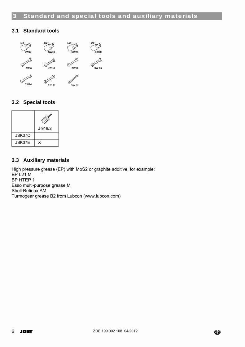
3 Standard and special tools and auxiliary materials
3.1 Standard tools0
3.2 Special tools0
0
3.3 Auxiliary materials
High pressure grease (EP) with MoS2 or graphite additive, for example: BP L21 M BP HTEP 1 Esso multi-purpose grease M Shell Retinax AM Turmogear grease B2 from Lubcon (www.lubcon.com)
J 919/2
JSK37C
JSK37E X
1/2´´
SW17
1/2´´
SW19
1/2´´
SW24
1/2´´
SW30
SW 8 SW 11 SW17 SW 19
SW24 SW 30 SW 24
7ZDE 199 002 108 04/2012
4 Repair work
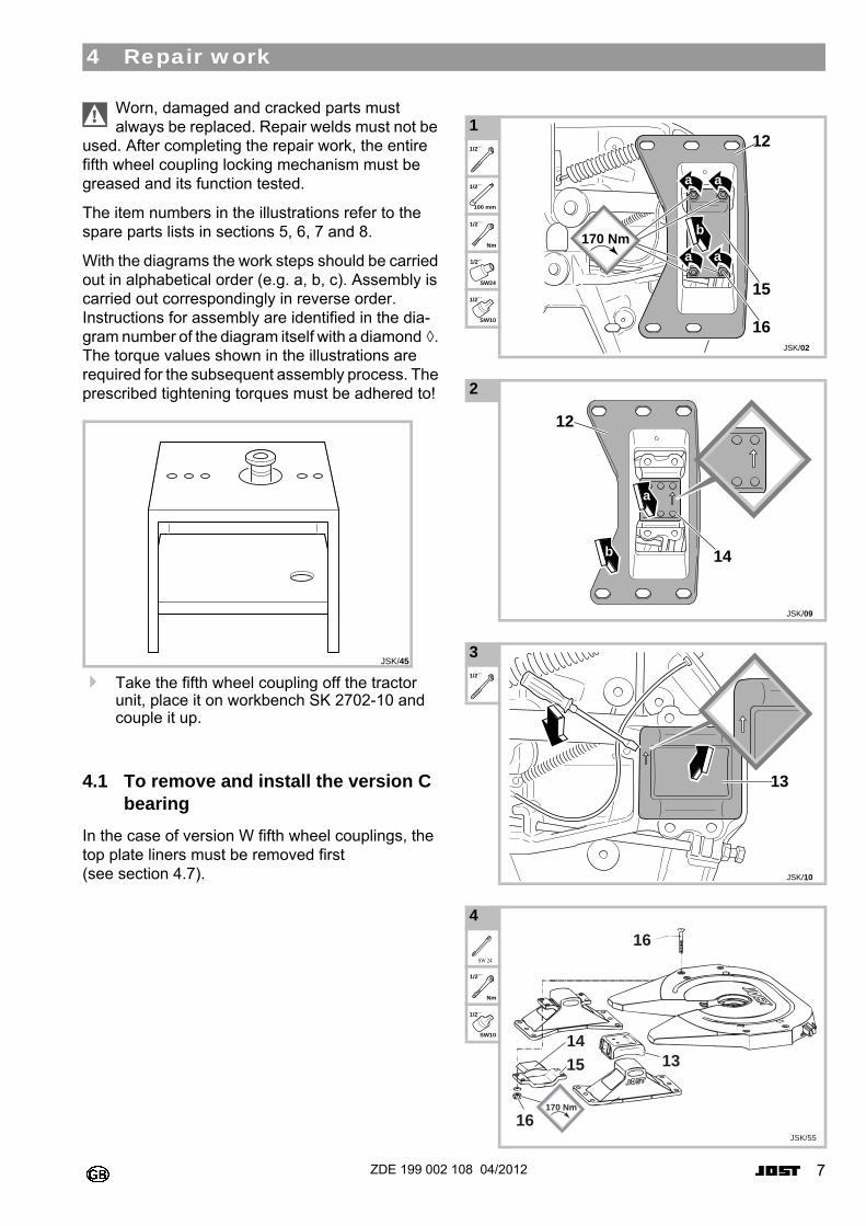
Worn, damaged and cracked parts must always be replaced. Repair welds must not be
used. After completing the repair work, the entire fifth wheel coupling locking mechanism must be greased and its function tested.
The item numbers in the illustrations refer to the spare parts lists in sections 5, 6, 7 and 8.
With the diagrams the work steps should be carried out in alphabetical order (e.g. a, b, c). Assembly is carried out correspondingly in reverse order. Instructions for assembly are identified in the dia-gram number of the diagram itself with a diamond ◊. The torque values shown in the illustrations are required for the subsequent assembly process. The prescribed tightening torques must be adhered to!0
Take the fifth wheel coupling off the tractor unit, place it on workbench SK 2702-10 and couple it up.
4.1 To remove and install the version C bearing
In the case of version W fifth wheel couplings, the top plate liners must be removed first (see section 4.7).
0
0
0
0
JSK/45
1 0
0
0
0
0
0
0
2 0
3 0
0
4 0
0
0
0
JSK/02
12
15
16
a a
b
aa
170 Nm
1/2´´
1/2´´
100 mm
1/2´´
Nm
1/2´´
SW24
1/2´´
SW10
JSK/09
a
b 14
12
JSK/10
13
1/2´´
16
16
1514
13
JSK/55
170 Nm
SW 24
1/2´´
Nm
1/2´´
SW10
8 ZDE 199 002 108 04/2012
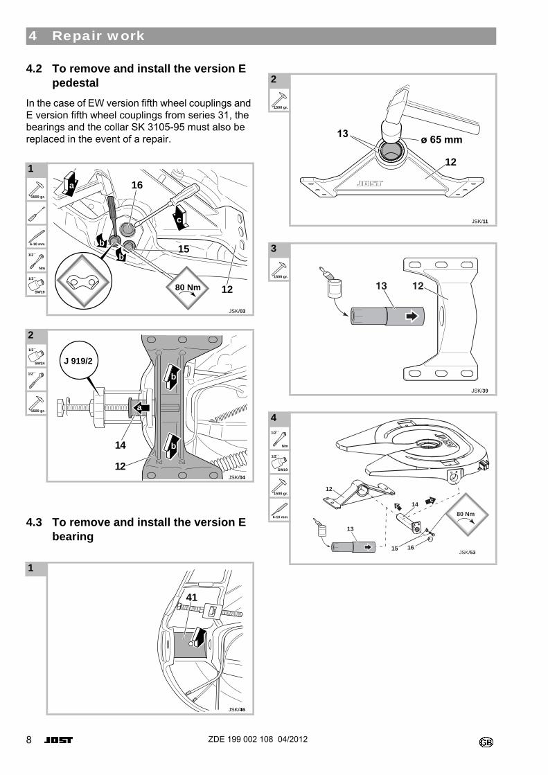
4.2 To remove and install the version E pedestal
In the case of EW version fifth wheel couplings and E version fifth wheel couplings from series 31, the bearings and the collar SK 3105-95 must also be replaced in the event of a repair.0
0
4.3 To remove and install the version E bearing
0
1 0
0
0
0
0
0
0
2 0
0
0
0
1 0
JSK/03
b
c
16
15
12
b
a
80 Nm
1500 gr.
6-10 mm
1/2´´
Nm
1/2´´
SW19
JSK/04
a
b
b14
12
J 919/21/2´´
SW24
1/2´´
1500 gr.
JSK/46
41
2 0
0
3 0
0
4 0
0
0
0
0
0
12
JSK/11
1500 gr.
JSK/39
12131500 gr.
13
c
12
14
15 16
c
80 Nm
JSK/53
1/2´´
Nm
1/2´´
SW19
1500 gr.
6-10 mm
4 Repair work
9ZDE 199 002 108 04/2012
4 Repair work
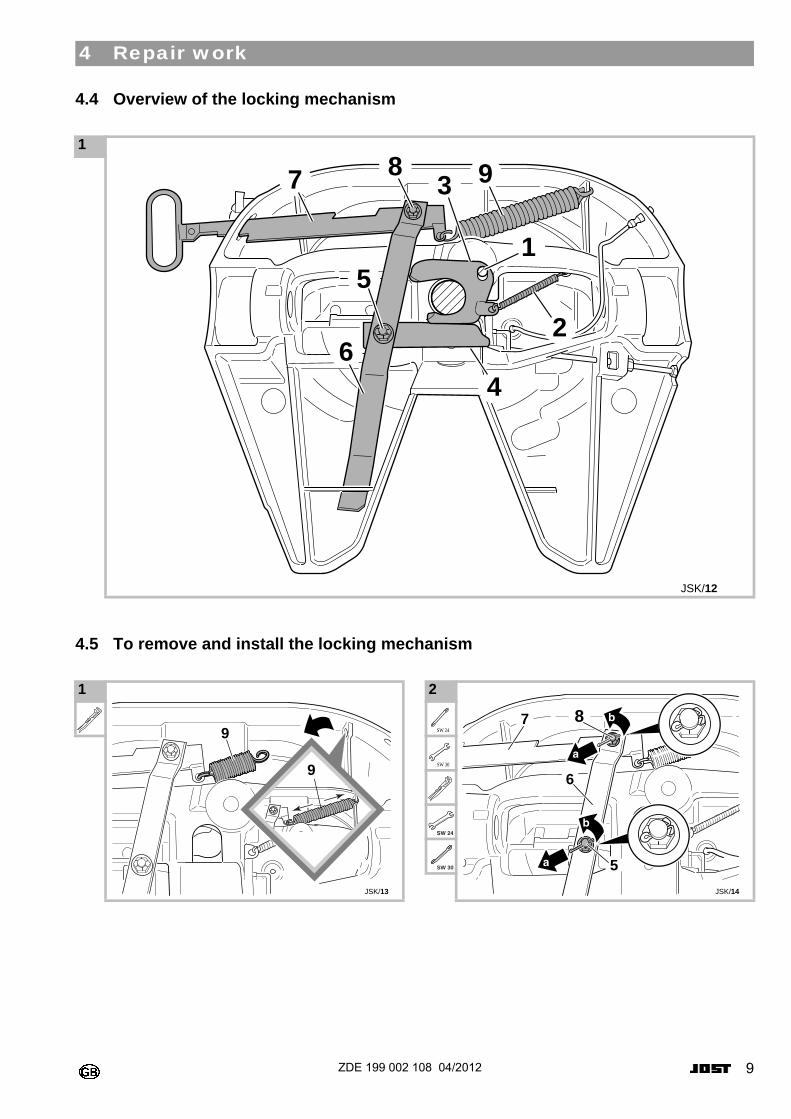
4.4 Overview of the locking mechanism0
4.5 To remove and install the locking mechanism0
0
0
1 0
JSK/12
98
2
4
1
7 3
6
5��
1 0
0
JSK/13
9
9
2 0
0
0
0
0
0
JSK/14
8
5
6
7SW 24
SW 30
SW 24
SW 30
10 ZDE 199 002 108 04/2012
4 Repair work
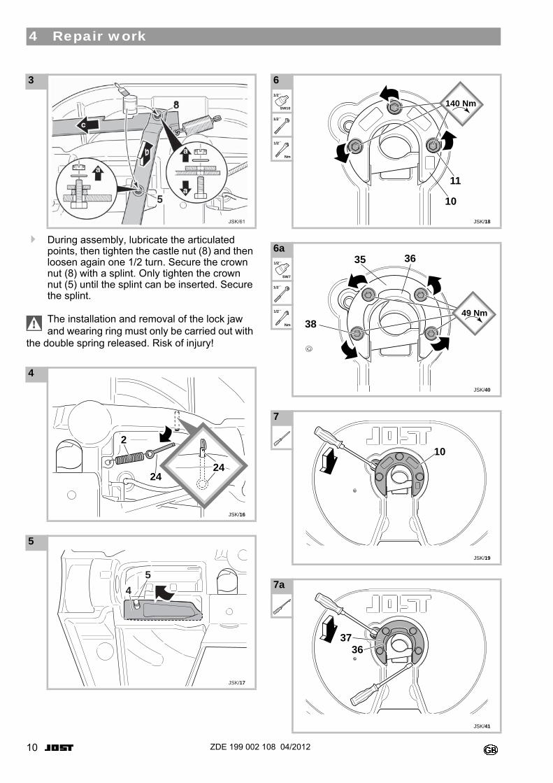
During assembly, lubricate the articulated points, then tighten the castle nut (8) and then loosen again one 1/2 turn. Secure the crown nut (8) with a splint. Only tighten the crown nut (5) until the splint can be inserted. Secure the splint.
The installation and removal of the lock jaw and wearing ring must only be carried out with
the double spring released. Risk of injury!0
0
0
0
0
0
0
3 0
0
4 0
0
0
5 0
0
0
JSK/61
JSK/16
2
2424
JSK/17
4
5
6 0
0
0
0
6a 0
0
0
0
7 0
0
7a 0
0
JSK/18
11
10
140 Nm1/2´´
SW10
1/2´´
1/2´´
Nm
JSK/40
38
35 36
49 Nm
1/2´´
SW7
1/2´´
1/2´´
Nm
10
JSK/19
JSK/41
3736
11ZDE 199 002 108 04/2012
4 Repair work
00
0
0
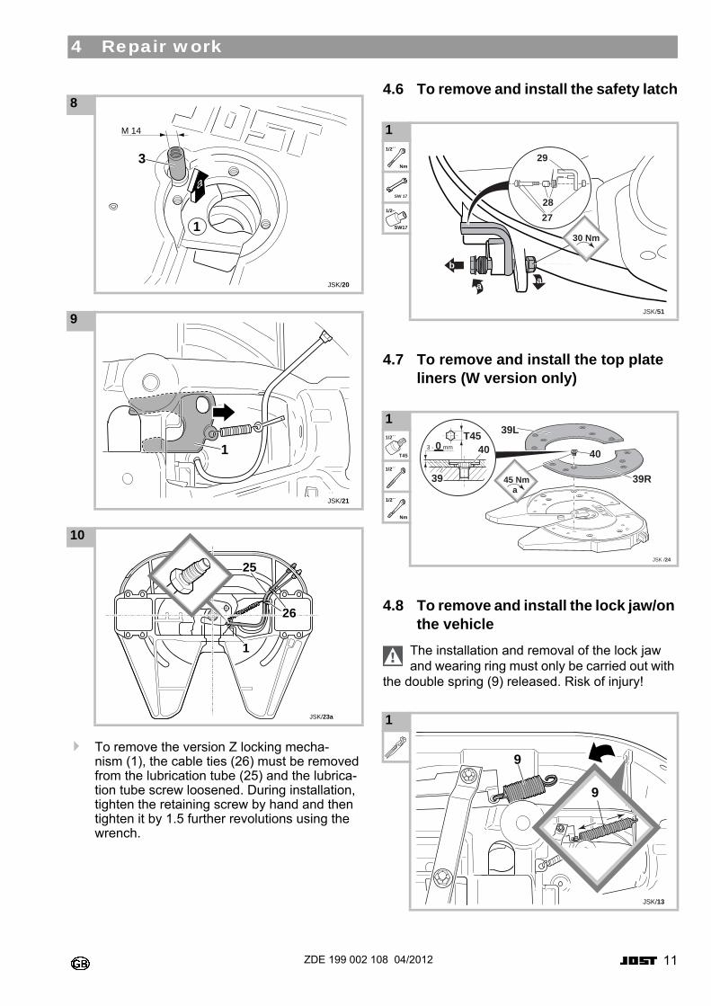
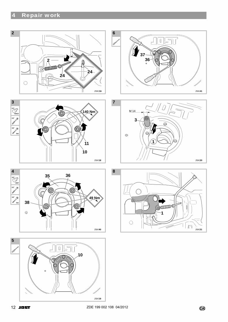
To remove the version Z locking mecha-nism (1), the cable ties (26) must be removed from the lubrication tube (25) and the lubrica-tion tube screw loosened. During installation, tighten the retaining screw by hand and then tighten it by 1.5 further revolutions using the wrench.
4.6 To remove and install the safety latch0
4.7 To remove and install the top plate liners (W version only)
0
4.8 To remove and install the lock jaw/on the vehicle
The installation and removal of the lock jaw and wearing ring must only be carried out with
the double spring (9) released. Risk of injury!0
8 0
0
0
9 0
0
0
10 0
0
0
JSK/20
3
1
M 14
JSK/21
1
1
JSK/23a
25
26
1 0
0
0
0
1 0
0
0
0
1 0
0
0
0
2728
29
b
a a
30 Nm
JSK/51
1/2´´
Nm
SW 17
1/2··
SW17
JSK /24
40
39L
39R
3 - 0 mm
T4540
39a
45 Nm
1/2´´
T45
1/2´´
1/2´´
Nm
JSK/13
9
9
12 ZDE 199 002 108 04/2012
4 Repair work
0
0
0
0
0
0
0
2 0
0
0
3 0
0
0
0
4 0
0
0
0
5 0
0
0
0
JSK/16
2
2424
JSK/18
11
10
140 Nm1/2´´
SW10
1/2´´
1/2´´
Nm
JSK/40
38
35 36
49 Nm
1/2´´
SW7
1/2´´
1/2´´
Nm
10
JSK/19
6 0
0
0
0
7 0
0
0
8 0
0
0
JSK/41
3736
JSK/20
3
1
M 14
JSK/21
1
13ZDE 199 002 108 04/2012
4 Repair work
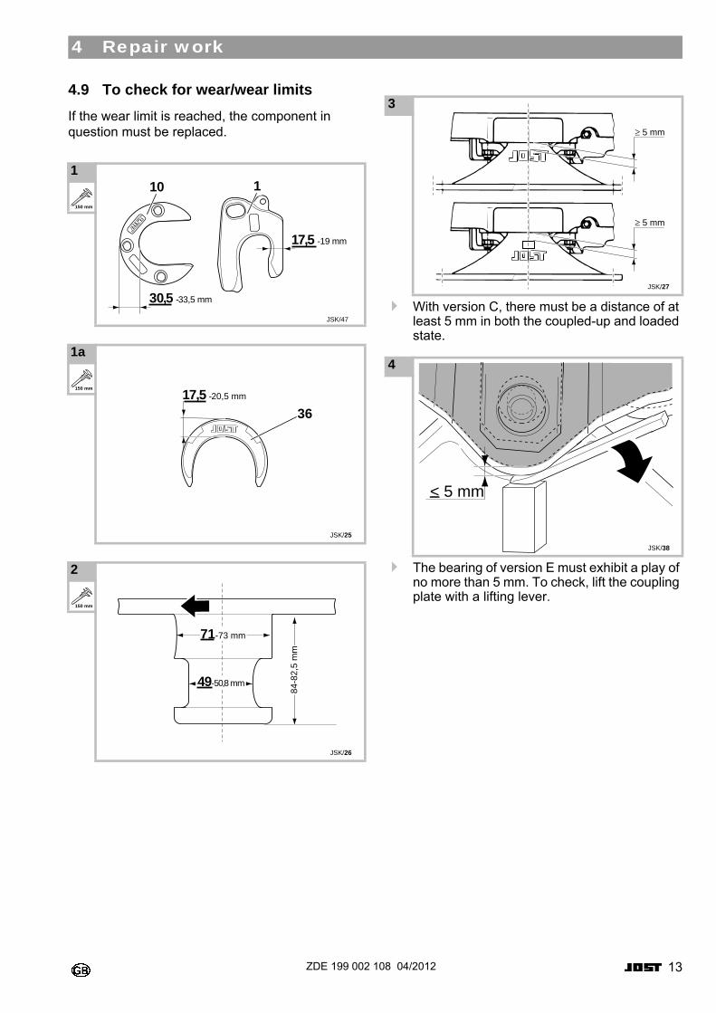
4.9 To check for wear/wear limits
If the wear limit is reached, the component in question must be replaced.0
0
0
0
0With version C, there must be a distance of at least 5 mm in both the coupled-up and loaded state.
0
The bearing of version E must exhibit a play of no more than 5 mm. To check, lift the coupling plate with a lifting lever.
1 0
0
0
0
1a 0
0
0
0
2 0
0
0
0
30,5 -33,5 mm
17,5 -19 mm
JSK/47
10 1150 mm
17,5 -20,5 mm
JSK/25
36
150 mm
71-73 mm
49-50,8 mm
84-8
2,5
mm
JSK/26
150 mm
3 0
0
0
0
4 0
0
0
0
JSK/27
≥ 5 mm
≥ 5 mm
JSK/38
< 5 mm
14 ZDE 199 002 108 04/2012
4 Repair work
0
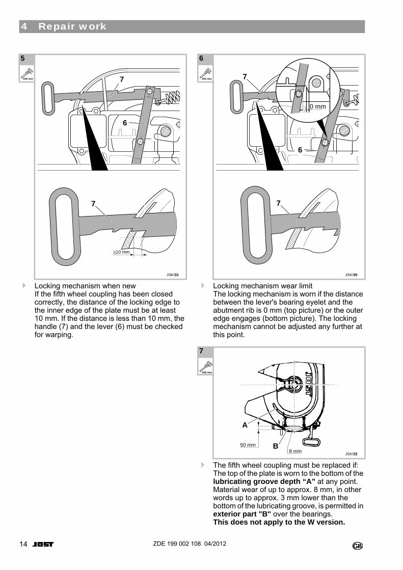
Locking mechanism when new If the fifth wheel coupling has been closed correctly, the distance of the locking edge to the inner edge of the plate must be at least 10 mm. If the distance is less than 10 mm, the handle (7) and the lever (6) must be checked for warping.
0
Locking mechanism wear limit The locking mechanism is worn if the distance between the lever's bearing eyelet and the abutment rib is 0 mm (top picture) or the outer edge engages (bottom picture). The locking mechanism cannot be adjusted any further at this point.
0
The fifth wheel coupling must be replaced if: The top of the plate is worn to the bottom of the lubricating groove depth “A” at any point. Material wear of up to approx. 8 mm, in other words up to approx. 3 mm lower than the bottom of the lubricating groove, is permitted in exterior part "B" over the bearings. This does not apply to the W version.
5 0
0
0
0
7
JSK/31
>10 mm
7
6
150 mm
6 0
0
0
0
7 0
0
0
0
JSK/30
7
7
6
0 mm
150 mm
8 mmJSK/32
B
A
50 mm
150 mm
15ZDE 199 002 108 04/2012
4 Repair work
0
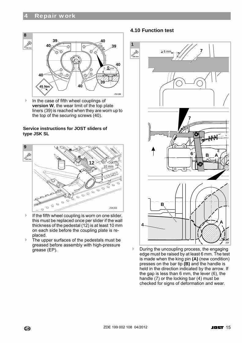
In the case of fifth wheel couplings of version W, the wear limit of the top plate liners (39) is reached when they are worn up to the top of the securing screws (40).
Service instructions for JOST sliders of type JSK SL0
0 If the fifth wheel coupling is worn on one slider, this must be replaced once per slider if the wall thickness of the pedestal (12) is at least 10 mm on each side before the coupling plate is re-placed.
The upper surfaces of the pedestals must be greased before assembly with high-pressure grease (EP).
4.10 Function test0
During the uncoupling process, the engaging edge must be raised by at least 6 mm. The test is made when the king pin (A) (new condition) presses on the bar tip (B) and the handle is held in the direction indicated by the arrow. If the gap is less than 6 mm, the lever (6), the handle (7) or the locking bar (4) must be checked for signs of deformation and wear.
8 0
0
0
0
9 0
0
0
0
JSK/43
3 - 0 mm
4039
39
40
3940
40
4045 Nm
150 mm
JSK/83
10 mm12
150 mm
1 0
0
0
0
JSK
> 6 mm
7
7
6
B
A
B A
4
150 mm
16 ZDE 199 002 108 04/2012
4 Repair work
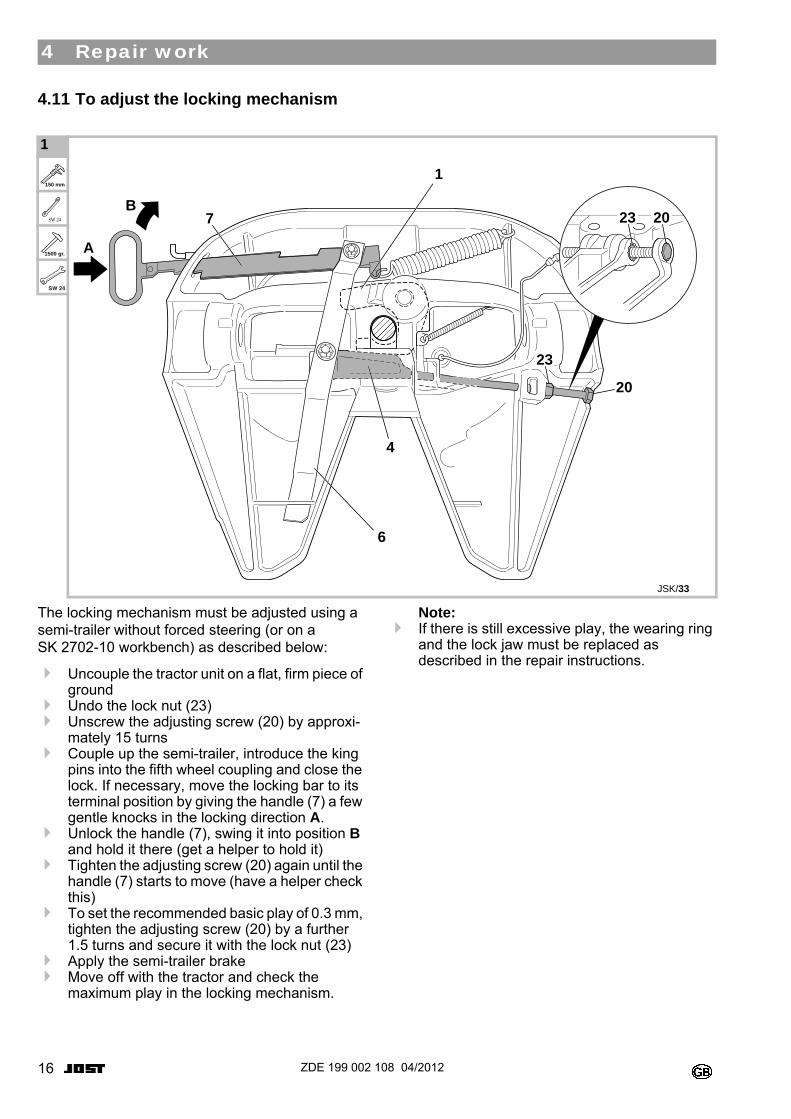
4.11 To adjust the locking mechanism0
The locking mechanism must be adjusted using a semi-trailer without forced steering (or on a SK 2702-10 workbench) as described below:
Uncouple the tractor unit on a flat, firm piece of ground
Undo the lock nut (23)Unscrew the adjusting screw (20) by approxi-
mately 15 turnsCouple up the semi-trailer, introduce the king
pins into the fifth wheel coupling and close the lock. If necessary, move the locking bar to its terminal position by giving the handle (7) a few gentle knocks in the locking direction A.
Unlock the handle (7), swing it into position B and hold it there (get a helper to hold it)
Tighten the adjusting screw (20) again until the handle (7) starts to move (have a helper check this)
To set the recommended basic play of 0.3 mm, tighten the adjusting screw (20) by a further 1.5 turns and secure it with the lock nut (23)
Apply the semi-trailer brakeMove off with the tractor and check the
maximum play in the locking mechanism.
Note: If there is still excessive play, the wearing ring
and the lock jaw must be replaced as described in the repair instructions.
00
1 0
0
0
0
0
0
23
23
20
7
4
20
6
1
JSK/33
A
B
150 mm
SW 24
1500 gr.
SW 24
17ZDE 199 002 108 04/2012
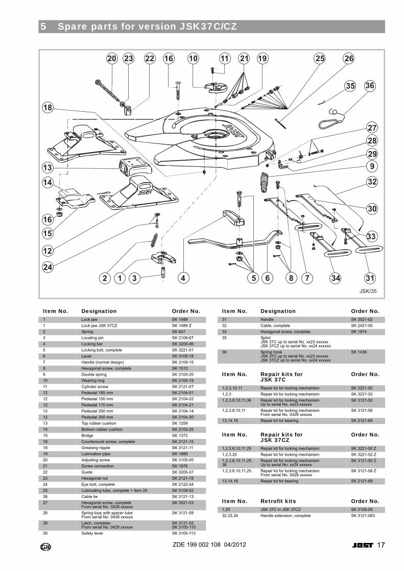
5 Spare parts for version JSK37C/CZ
0
0 0
0
0
0
JSK/35
1122 16 102320 21 19 25 26
2728299
30
32
33
34786431224
12
1516
14
13
18
315
35 36
Item No. Designation Order No.1 Lock jaw SK 1489
1 Lock jaw JSK 37CZ SK 1489 Z
2 Spring SK 847
3 Locating pin SK 2106-67
4 Locking bar SK 3205-06
5 Locking bolt, complete SK 3221-01
6 Lever SK 3105-18
7 Handle (normal design) SK 3105-15
8 Hexagonal screw, complete SK 1513
9 Double spring SK 3105-20
10 Wearing ring SK 2105-19
11 Cylinder screw SK 2121-07
12 Pedestal 185 mm SK 2104-01
12 Pedestal 150 mm SK 2104-02
12 Pedestal 170 mm SK 2104-21
12 Pedestal 250 mm SK 2104-14
12 Pedestal 300 mm SK 2104-20
13 Top rubber cushion SK 1259
14 Bottom rubber cushion SK 2105-25
15 Bridge SK 1372
16 Countersunk screw, complete SK 2121-15
18 Greasing nipple SK 3121-11
19 Lubrication pipe SK 1989
20 Adjusting screw SK 3105-05
21 Screw connection SK 1976
22 Guide SK 3205-07
23 Hexagonal nut SK 2121-78
24 Eye bolt, complete SK 2122-04
25 Lubricating tube, complete + item 26 SK 3108-02
26 Cable tie SK 3121-13
27 Hexagonal screw, complete From serial No. 0428 xxxxxx
SK 3521-03
28 Spring loop with spacer tube From serial No. 0428 xxxxxx
SK 3121-59
29 Latch, complete From serial No. 0428 xxxxxx
SK 3121-52 SK 3105-115
30 Safety lever SK 3105-113
Item No. Designation Order No.31 Handle SK 3521-02
32 Cable, complete SK 2421-50
33 Hexagonal screw, complete SK 1974
35 Splint JSK 37C up to serial No. xx23 xxxxxx JSK 37CZ up to serial No. xx24 xxxxxx
36 Spring hook JSK 37C up to serial No. xx23 xxxxxx JSK 37CZ up to serial No. xx24 xxxxxx
SK 1436
Item No. Repair kits forJSK 37C
Order No.
1,2,3,10,11 Repair kit for locking mechanism SK 3221-50
1,2,3 Repair kit for locking mechanism SK 3221-52
1,2,3,8,10,11,36 Repair kit for locking mechanism Up to serial No. xx23 xxxxxx
SK 3121-50
1,2,3,8,10,11 Repair kit for locking mechanism From serial No. 0428 xxxxxx
SK 3121-56
13,14,16 Repair kit for bearing SK 2121-69
Item No. Repair kits forJSK 37CZ
Order No.
1,2,3,8,10,11,25 Repair kit for locking mechanism SK 3221-50 Z
1,2,3,25 Repair kit for locking mechanism SK 3221-52 Z
1,2,3,8,10,11,25, 36
Repair kit for locking mechanism Up to serial No. xx24 xxxxxx
SK 3121-50 Z
1,2,3,8,10,11,25 Repair kit for locking mechanism From serial No. 0428 xxxxxx
SK 3121-56 Z
13,14,16 Repair kit for bearing SK 2121-69
Item No. Retrofit kits Order No.1,25 JSK 37C in JSK 37CZ SK 3108-05
32,33,34 Handle extension, complete SK 3121-063
18 ZDE 199 002 108 04/2012
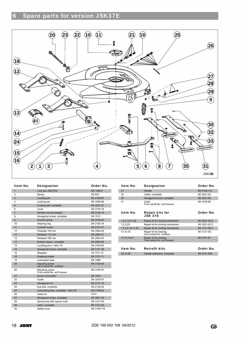
6 Spare parts for version JSK37E
0
0 0
0
0
JSK/36
2122 10 1123 19 25
26
2728
29
9
30
32
33
3576432 1
15
16
24
14
13
12
18
315 8
20
Item No. Designation Order No.1 Lock jaw JSK37AZ SK 1489 Z
2 Spring SK 847
3 Locating pin SK 2106-67
4 Locking bar SK 3205-06
5 Locking bolt, complete SK 3221-01
6 Lever SK 3105-18
7 Handle (normal design) SK 3105-15
8 Hexagonal screw, complete SK 1513
9 Double spring SK 3105-20
10 Wearing ring SK 2105-19
11 Cylinder screw SK 2121-07
12 Pedestal 150 mm SK 2904-42
12 Pedestal 172 mm SK 2904-41
12 Pedestal 185 mm SK 2904-40
13 Rubber sleeve, complete SK 2905-94
14 Locating pins + item 16 SK 3104-05
15 Hexagonal screw, complete SK 3121-28
16 Stoppers JS 1101-12
18 Greasing nipple SK 3121-11
19 Lubrication tube SK 1989
20 Adjusting screw Up to serial No. xx28xxx
SK 3105-05
20 Adjusting screw From serial No. xx31xxxxxx
SK 3105-97
21 Screw connection SK 1976
22 Guide SK 3205-07
23 Hexagonal nut SK 2121-78
24 Eye bolt, complete SK 2122-04
25 Lubricating tube, complete + item 26 SK 3108-02
26 Cable tie 3121
27 Hexagonal screw, complete SK 3521-03
28 Spring loop with spacer tube SK 3121-59
29 Latch, complete SK 3121-52
30 Safety lever SK 3105-115
Item No. Designation Order No.31 Handle SK 3105-113
32 Cable, complete SK 3521-02
33 Hexagonal screw, complete SK 2421-50
41 Collar From serial No. xx31xxxxxx
SK 3105-95
Item No. Repair kits for JSK 37E
Order No.
1,2,3,10,11,25 Repair kit for locking mechanism SK 3221-50 Z
1,2,3,25 Repair kit for locking mechanism SK 3221-52 Z
1,2,3,8,10,11,25 Repair kit for locking mechanism SK 3121-56 Z
13,14,15 Repair kit for bearing Up to serial No. xx28xxx
SK 3121-58
13,14,15,41 Repair kit for bearing From serial No. xx31xxxxxx
SK 3121-61
Item No. Retrofit kits Order No.32,33,35 Handle extension, complete SK 3121-063
19ZDE 199 002 108 04/2012
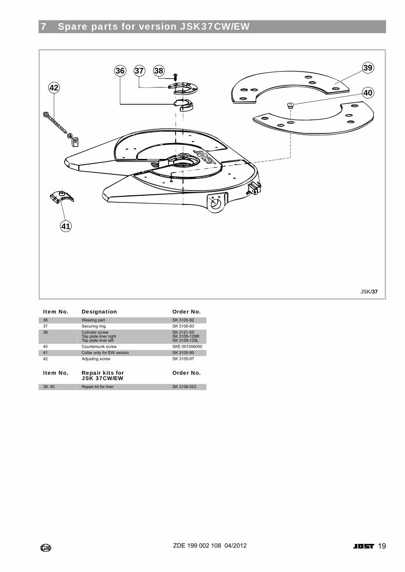
7 Spare parts for version JSK37CW/EW
0
0
0
36
41
40
3937 38
JSK/37
42
Item No. Designation Order No.36 Wearing part SK 3105-92
37 Securing ring SK 3105-93
38 Cylinder screw Top plate liner right Top plate liner left
SK 3121-55 SK 3105-129R SK 3105-129L
40 Countersunk screw SKE 001006000
41 Collar only for EW version SK 3105-95
42 Adjusting screw SK 3105-97
Item No. Repair kits for JSK 37CW/EW
Order No.
39, 40 Repair kit for liner SK 3106-003
20 ZDE 199 002 108 04/2012
8 Disposal instructions
The mounted parts are valuable raw materials that can be recycled. They can be split into plastics, rubber and metallic materials. The plastics and rubber materials are identified pursuant to VDA Recommendation 260. All oil and grease is to be cleaned off the parts before their disposal.

Siemensstraße 2, D-63263 Neu-Isenburg, Telefon +49 6102 295-0, Fax +49 6102 295-298, www.jost-world.comZDE 199 002 108 04/2012