replacement of co-base alloy for radiation exposure
TRANSCRIPT

K AERI/RR-1584/95 KR9600210
Replacement of Co-base Alloy for Radiation Exposure Reductionin the Primary System of PWR
VOL 2 C ."? 0 5

KAERI/RR-1584/95
Replacement of Co-base Alloy for Radiation Exposure Reductionin the Primary System of PWR

1996. 1.
O|
812}
NEXT PAQE(S)toft BLANK

I.
II.
M,
Co-free
* ^it[ Co reduction programs]
Co t e ^ H S CH^ » S t f ^r 2 i ^ Co
o|» fl^oi 7 |^ Co
Ofu|BK
III. sl LH§ a!
1. Co-free
. ^ Stellite
0:f 7H^£I OjSj fig § , STflfig 2#(Armacor M, Tristelle 5183)2f
488)S £ § ^ 2 * ° ^ , O|§ *^2f 7|^fij Stellite 6
a 316SS ax(jcH| TIG
2. Test loop2 f ^ f | ! « SAW ^ Si^ ^^ |A |§§ test
^Qi , O| § U | * 0 | § t ^ 300°C, 1500
3. | J
^ 4 #
, HAZ,
4. 7|#H^Sff M1
S 3 1*WI* SSM gfi^HH# 7|£2j Co-base Stellite * ^ £ £
Co-free f g o g qj^|§fe 7|^2f fiJS«fOi, ^ ^ ^M2J Aj§BF Co-free
5.
- IV -

IV. g^Sii l a! Wgoil cue
1. Co-free
Co-free * S S S -idSq^OllAi
o|ft s
2 # (Armacor M, TristeUe 5183),
(Nucalloy 488)O|&|, 7|^2j q j n f e ^ s ^ Afgs j i °ife Stellite
Jfe. TIG
316SS
2. Test loop
I*MISSI
= S &7\t\3Ln, fil^S] loop
loop s a g s § s # a gs*F<>< s ^ ^ ^ ^i^s ^ ^ i s s test. 0| loop°J ^ ^ A | S 2Bf, g*|| system^
fe ^S§-^(autoclave L|J¥)O| ± 0°C,
3. ^ | S
test loop# 0|S*W 300r, 1500 psi,
- v -

o|StelUteSf Nucalloy
Armacorfif Tristelle2| g
4.
. Armacor
. 01 EHS-
fe Fe2B
Nucalloy
SteUite
5. 7|^?
S3Co-free S ^ £ S
Co a! Co-free S
21 SSSI Co-free
Co-base Stellite | B °
6.
- vi -

Summary
I. Project Title
Replacement of Co-base Alloy for the Radiation Exposure Reduction in
the Primary System of PWR
II. Objective and Importance of the Project
The purpose of this project is to establish the technical guidelines for
the replacement of cobalt containing materials in valve components in the
nuclear power plants where these components could contribute significantly
to the cobalt inventory reaching the reactor core. Numerous studies such
as the characterization of Co-free alloys and the consideration of design
requirement and regulatory requirement should be performed to consolidate
the cobalt reduction program in the domestic nuclear power plants.
III. Scope and Contents of Project
1. Selection of Co-free alloys and welding
Of numerous Co-free alloys developed to replace Co-base Stellite
used in valve hardfacing material, two iron-base alloys of Armacor M and
Tristelle 5183 and one nickel-base alloy of Nucalloy 488 were selected as
candidate Co-free alloys of this project, and Stellite 6 was also selected as
- vu -

a standard hardfacing material. These four alloys were welded on 316SS
substrate using TIG welding method.
2. Design and fabrication of test loop, and corrosion test
The first corrosion test loop of KAERI simulating the water
chemistry and operation condition of the primary system of PWR was
designed and fabricated in this project. Corrosion behaviors of the above
four kinds of alloys were evaluated using this test loop under the condition
of 3001), 1500 psi, and the simulated primary water chemistry.
3. Microstructural observation and hardness measurement
Microstructures of weldment of these alloys were observed to
identify both matrix and secondary phase in each weldment. Hardnesses of
weld deposit layer including HAZ and substrate were measured using
micro-Vickers hardness tester.
4. Analysis on the status of the Co replacement technology
The status on the technology of Co-base alloy replacement in valve
components was reviewed with respect to the classification of valves to be
replaced, the development of Co-free alloys, the applications of Co-free
alloys and its experiences in foreign NPPs, and the Co reduction program
in domestic NPPs and industries.
5. Basic study for wear tests
For the evaluation of wear property of various Co-free alloys, wear
- vtii -

test technologies were studied to establish a proper test method for
hardfacing materials of valve components.
IV. Result and Proposal for Application
1. Selection of Co-free alloys and welding
Two iron-base alloys of Armacor M and Tristelle 5183 and one
nickel-base alloy of Nucalloy 488 as candidate Co-free materials were
selected in this project excluding other Co-free alloys which have been
utilized in the nuclear power plants. Weld specimens of these three alloys
and Stellite 6 as a standard hardfacing material were fabricated by TIG
welding on 316SS substrate.
2. Design and fabrication of corrosion test loop
The first corrosion test loop of KAERI simulating the water
chemistry and operation condition of the primary system of PWR was
designed and fabricated by ourselves in this project. From the performance
tests of this loop, it can be found that this loop will be able to operate
within the range of ± OTC and ± 1TC for the test solution and the
preheated feedwater, respectively, with no-leakage of solution in the whole
system, and to maintain within the pressure range less than 10% of
design pressure.
3. Corrosion evaluation
Corrosion behaviors of the above four alloys were evaluated using

this test loop under the condition of 300 "C, 1500 psi, and the simulated
primary water chemistry. Two kinds of specimens consisting of weld deposit
layer only and weld/feubstrate were used in corrosion tests. It was shown
that the corrosion resistance of both Stellite and Nucalloy was superior to
that of two iron-based alloys of Armacor and Tristelle. The corrosion
behaviors for both Stellite and Nucalloy having the negative weight
changes for a certain period could be interpreted as the phenomena due to
the dissolution of specific constituent from the weldment as well as a
formation of stable oxide film on the surface of these alloys.
4. Microstructural observation and hardness measurement
Microstructures of weldment of four alloys were observed to
identify both matrix and secondary phase in each weldment. Armacor M
was composed of a peculiar needle-like microstructure which did not
developed in a typical welding structure. This needle-like microstructure
was a kind of eutectic phase consisted of secondary phase(Cr2B) and
lamella structure(Fe2B). The other three alloys had typical casting
microstructures with the various kinds of intermetallic compounds and
carbides formed in each alloy system. The highest hardness was obtained
in Nucalloy alloy, thus it can be expected that Nucalloy will have a good
property with respect to the wear resistance.
5. Analysis on the status of the Co replacement technology
The status on the technology of Co-base alloy replacement in valve
components was reviewed with respect to the classification of valves to be
- x -

replaced, the development of Co-free alloys, the applications of Co-free
alloys and its experiences in foreign NPPs, and the Co reduction program
in domestic NPPs and industries.
- xi - I NEXT PAGE(S)I left BLANK

1
m Hfl s i
2 ^ PWR lSl-^ifl s£S«Qf^l $*§$• °)$ ^-dtcfl^ 2
^- £ €• 5
1 3 ^^vfl-g- ^ U"^ 5
1. JMH^-8- test loop $*[ % Co-free ^ ^%7}*]-% 5
2. 7l^7fl t^^" £A4 5
2 ^ Co-free ^ ^d^ -g-^ 6
1. Co-free ^ 4 ] ^ 6
2. ^ g-g-o} ^-^ 6
3. •&•$ 12
3 ^ Test loop ^Tfl, ^ 1 ^ - % ^ - ^ ^ 1 ^ 14
1. 7fl.fi. 14
2. Test loop -a^l ^114 17
3. JMMH 24
4 | nl^^a] ^ - ^ ^ ^£4^9 31
1. n j^a) -4} 31
2. 33E # ^ 36
5 ^ 7l 7fl#^3§- $q 39
1. aJ«.^'l tfl^l7l# 39
2. ^-ifl-^ 7l#t&# 55
- xin -

691. ! « . ^ ^ S . ^ f^A^ nj-stgEfl 69
2. HWL ^ ^ S *l-S.^Jg7W ^ t t ! : 4 a ^ l ^ ^ 77
3. ^ A ^7fifl-§- 83
86
89
- xiv -

s.
Table 1 Cobalt alloy sources in PWR 3
Table 2 Mechanical and physical properties of various
hardfacing alloys 7
Table 3 Composition of hardfacing alloys 8
Table 4 Properties of hardfacing alloys 10
Table 5 TIG welding condition 13
Table 6 Corrosion test condition simulating the primary
coolant chemistry 26
Table 7 Eletrolytic polishing condition for various weld metal 31
Table 8 Comparison of cobalt wear rates in various type of
valves measured using two different methods 45
Table 9 Decrease of Co-60 and radiation dose with cobalt
source reduction 48
Table 10 Priority of valves for cobalt alloy replacement 49
Table 11 Chemical composition of various hardfacing alloys 50
Table 12 Specific details about the Co removal programs
in the U.S. utilities and plant 59
Table 13 Example of Co-free alloy application in Ontario
Hydro's Pickering B plant 61
Table 14 The Swedish nuclear program for replacement
of Co-based alloys 62
Table 15 Vendor cobalt-free valve offerings 65
Table 16 Status of domestic nuclear power plants 68
Table 17 Status of domestic valve manufacturing industries 70
Table 18 Operation time and velocity of gate valve
with valve diameter 80
- xv -

Fig. 1 Effect of dissolved oxygen and hydrogen on corrosion
potential of 304 stainless steel in 288°C water 15
Fig. 2 Equilibrium potential-pH stability diagram for
iron-water system at 288°C 16
Fig. 3 Design diagram of primary water simulation test loop 18
Fig. 4 Photos of primary water simulation test loop
manufactured in this project 22
Fig. 5 Dimensions of corrosion test specimens 25
Fig. 6 Corrosion of single layer hardfacing specimens
under the simulated primary coolant 27
Fig. 7 Corrosion of 3 layers hardfacing specimens under
the simulated primary coolant 28
Fig. 8 Corrosion of exclusive hardfacing layer under
the simulated primary coolant 29
Fig. 9 Microstructure of weld deposited layer
(Armacor M, 3 layers) 32
Fig. 10 SEM fractography showing the different morphology
of weld deposited layer (Armacor M, 3 layers) 34
Fig. 11 Microstructure of weld deposited layer
(Nucalloy 488, 1 layer) 35
Fig. 12 Microstructure of weld deposited layer
(Stellite 6, 3 layers) 37
Fig. 13 Microstructure of weld deposited layer
(Tristelle 5183, 3 layers) 38
Fig. 14 Macrosection and hardness in the cross section
(Substrate-316SS, TIG welding) 40
- xvi -

Fig. 15 Hardness of weld deposit for various hardfacing
materials (Substrate-316SS) 41
Fig. 16 Hardness of 3-layers weld deposit for various
hardfacing materials (Substrate-316SS) 42
Fig. 17 Variation of hardness with weld deposited layers 43
Fig. 18 Schematic for implementing a cobalt
reduction program 46
Fig. 19 Co replacement of PWRs 57
Fig. 20 Dimension of wear specimen 82
- xvii -

^ ICRP 60^
(radiation field)^ 40]
^ 80
1*1-7(1-g-ifl
2 rem-$.S
ALARA
], 7j]f-vfl
5U
^ Co reduction
program
low Co £fe Co-free t ^
- 1 -

3:47V
low Co/Co-free ^ ^ - ^ ^ ^
nl^jfe i 7 | ^ f Jg7V ^ 4 ^^r A i 7 l # 7 f l ^ &<>&. sfl^
PWR
PWR -£*} l^Tflf- "o1"^^0!! 7l«^*>^ ^ A « j f ^ Co-604 Co-58olc|-. o]
C0-6O0I
Co-597>
Stellite-64
spacer grid -fs] q ^ t^"2!- €^>5.ifl^- ^-#, ufl^fl #S) i^oi^ l - ! : 7J- ^
control rod drive mechanism (CRDM), «J«. ^ «fl<H
S.* 50-60 % fl-fr^- SteUite ^-^-^.
^(hardfacing)
- 2 -

Z\7] t}.H
, CRDM gj
«• ^ 1 -
7)
Table 1. Cobalt alloy sources in PWR.
Source
S/G Tube Corrosion
Valve Maintenance
CRDM Wear
Check Valve Wear
Gate Valve Wear
Main Coolant Pump
Shaft Wear
Annual Release
Rate/Plant
(gfrr)
33-55
10-30
2-5
1
0.5
0.2
- 3 -

fl 600A5. Y ^ ^IS^l 690^
^ S^-S. -i-£l~g- 0.04 %oflA-j 0.015 %S. #±*\H ^ 9X^*\ ^^S- spacer
gridt <ya^ ^-9- tfl^l Zircaloy# Aj-g-^fe T^^- CO-60^ ^ ^ 25-50 % ^
£ #°J ^r SU4I1]. 61^°11 EPRI ^«fl 5] 8))
pH
[1].
- 4 -

1. Y^^l^-S- test loop ^m ^ Co-free ^-^ ^
^*>^, PWR
test loop*
fe- Co-base Stellite 6
316SS a^ofl TIG ^
2.
Co-base Stellite
^ Co a fe Co-free ^-^^-S . cfl^l^>^ 7l^ofl 9l°]*\, rfl-*
Co-free ^
- 5 -

Co-free
1. Co-free
Co-f ree t^"* BM
13) (iron-base), ^ 3 1 (nickel-base) t
A ^ , 5. 2<H11 * ^ $1^ «>^ ^ o l ^ Co^-^-4 Co-free
9X 4 . °1 f1^^ NOREM, Deloro, Colmonoy, Event, Cenium
A : Armacor M
N : Nucalloy 488
S : Stellite 6
T : Tristelle 5183
2. A
Co-free W l "steinte --g- cfl l ^fi.?iis.s ^e«fl ^m^l
4 i W&i } . ^ i ^ ^ t ^ ^ A - j f e Armacor
M, Tristelle 5183 1 ^ ^ ] ^ ^ - 2*. Nucalloy 488^
tJWS.*flj3.5. A>^E|ji $ i^ stellite
-6 -

Table 2. Mechanical and physical properties of various hardfacing alloys.
1
AlloyHardness
Room Temp.,HRC
TensileStrength, ksi
CharpyImpact
Strength,ft-lb
Coeff. ofThermal
Expansion(70-1100-F),
X106
High Cobalt AlloysStellite 6
Co-156
Co-12
Coast Metal 6
39-43
46-50
45
43-47
----
17
-
-
-
8.1
-
-
-
Low Cobalt AlloysHaynes 711
Haynes N-6
RHDIIG
Tristelle 1
Tristelle 2
43-47
30-32
38-40
-
-
-
---
-
-
-
13.8
4.0
-
-
-
-
-
Nickel Based Co-free Hardfacing AlloysColmonoy 4
Colmonoy 5
Colmonoy 6
Colmonoy 74
Colmonoy 84
Deloro 40
Deloro 50
Cobex 547
Tribaloy T700
Vertex 4776
35-40
45-50
56-61
38-40
38-44
29-41
46-49
41-42
42-45
47-48
-60
30
-
-
-
-
-
-
-
-
3
1.5
-
-
2.8
2
-
-
-
-
8.2
8.2
-
-
7.7
7.2
-
-
-
Iron Based Co-free Hardfacing AlloysAntinit DUR 300
Cenium Z20
Cenium 37
EB5183
Everit 50
NITRONIC 60
NOREM 01
RHDIC
SKWAM
28-32
42-48
38-41
40.5
47-53
25
45
41-46
36-42
115
61
-
-
-
123
80
-
-
-
-
-
5.5
-
54
4.2
-
-
9.2
7.8
-
8
9.6
10.19.1
-
-
- 7 -

Table 3 Composition of Hardfacing Alloys( wt % )
Alloy
Armacor-M
(A)
Nucalloy 488(N)
Stellite-6
(S)
Tristelle 5183(T)
Cr
26.5- 30
18.4
33
24.7
Ni
--
Bal.
3
11.7
Fe
Bal.
6.6
3
Bal.
Co
--
--
Bal.
0.3
C
0.2
max.
0.26
1.1
1.59
Mn
2.0-2.6
-
--
0.1
W
--
1.3
6
--
Si
1.2-1.6
7.7
-
5.4
B
3.5-4.0
--
--
-
Sn
-
0.9
-
-
Nb
--
--
--
5.4
Remark
Fe-base(amorphous)
Ni-basel)
Co-base
Fe-base2)
1) P < 0.01, S = 0.005, others < 0.52) Mo < 0.1, others < 0.5

f. A
vol a]^^(amorphous)
fe metamorphic
solid state amorphous transformation0!
r - B ^ 5 . ^^s j«H 5U^-^, Si
«13 £3
9X7}
*4. N W
61 U^-cr Ni-based
- ]-7l] iS j -^ l^ 7| --S] Co-base
NiCr-A, NiCr-B -f-4 ^ ^ - 7 l^ .
BWR «fl>H Co
- 9 -

Table 4. Properties of hardfacing alloys,a) hardness values, HV(5)
Alloy
ST-6
ARM
5183
488
RT
730,HV(30)
502
200 r
740
4001C
448
500 TC
500
440
6 0 0 1
437
7 0 0 1
190
401
Remark
PTA - 2 layers,(Base H-13)
OxyacetyleneDeposits
b) thermal expansion coefficient, (x 10'6/°C)
Alloy
ST-6
AR-M
5183
488
Temperature Range, °C
RT/100
11.3
10.8
RT/200
11.9
12.0
RT/300
12.9
12.2
RT/400
13.2
12.5
RT/500
13.4
12.8
RT/600
14.0
13.0
RT/700
14.6
13.4

Alloy
Table 4. (Continued), c) physical and mechanical properties,
Alloy
ST-6
AR-M
5183
488
Density,(g/fcm3)
7.3
7.5
8.1
RHC
31-40 (MIG)55-65 (as coated)71 (as applied)
41(30.4*)
45(38.8*)
UTS (kg/mm2)
RT
96.4
High Temp.
95.3, 80.2(400t), (6001:)
Impact Strength (kg-m)(Charpy un-notched)
RT
0.8
0.6
High Temp.
0.6, 0.7(400t), (600r)
Remark
*A11 weldhardness
it
d) wear properties.
FrictionCoefficient
Wear LossCounterRotatingCylinder
(mg)
Pin onDisk
(mm3).
Abrasion,ASTM G-65
Proc. Amm3 (or g)
Abrasion,ASTM G-65
Proc. Bmm3 (or g)
Remark
ST-6
AR-M
5183
488
120(0.957)
(T)(PS)
123.1 (M)
D : 0.09S : 0.14
14.5(0.112)
(M) 18 (0.13)14.8 (M)
D : DynamicS : StaticT : TIGM : MIGPS : Plasma
Spray

Ni JL-g-*ll, Ni3Si, NisB ^°1
carbide £ boride «g41-0l 71*1^3 MH jl^7]| £ ^ # 5 j - 5 ^ tfl
. T
Cr 7
3. -
Co-free t^ -^-S . 7fll-5l<H #-§-21- # ? H o|# EB 5183
9l$r •§• ^ ^ Co ^ - ^
Nb ^fl-l-ol j l Cr austenite
w i r e £ -
1.6 mrn l -g-^ wire^l^, UJ-P]^ N, S, T 3^-8:
3.2 ramSl -g-^^olcf. ^ i - -g-^7fl£.t- «»|^.*).^f ^£*\] « Ja .^^
4 ^ TIG ^-^-g-^^^-5 . 316 stainless steel (316SS)
3-7)1= 50X50X11 (rnmHH, 4 *
5L^°\} tflsfl -g -^## 1^(1 layer) ^ 3^(3 layers)^
oll-& 4 4 Al, A3 ^ 4 ^o] 5.^
2, 4 mm =SH*15a4. S. 5 ^ TIG ^
- 12 -

Designation(Material/Layer)
Al
A3
Nl
N3
SI
S3
Tl
T3
Material
Armacor M
Nucalloy 488
Stellite 6
Tristelle5183
Table
Current
(A)
50
60
60
70
60
70
60
70
5. TIG welding condition.
Interpass
Temp.CC)
400
500
500
600
400
500
400
500
Heat Treatment
Per
300 °C
Post-Weld(*)
-
o-o-o-o
Weldability
good
ft
fair
rr
good
rr
ft
tt
Defects in Weldlayer
microcrack
micropore
(*) 400°C, lOdays, furnace coolingcooling rate : l°C/min

3 *I Test loop
1. 7fl.fi.
2.2-3.5 ppm lithium (IiOH) gj 315-1,800 ppm
boron (H3BO3)°1 %7}£\ZL, 5 ppb °}Z}2\ •%•&&&% $ 15-35 cc H2 STP^cg
watery ^ r i ^ i 2L£O] .fl^slfe pH 6.9-7.43] 2:^0]t|..
(corrosion potential)7l- -g-#
1-& -g-e <L>^^ 5? ^ r^^^ l 304 ^Bll-ye
H , n ^ 2fe ^ - ^ ^ ^ 1 4 pH
Pourbaix diagram^
static autoclavel-
5 -^7f autoclaveofl 4e)- ^ ^ o ] ^ ) ^ ^ 5 > J I £ ^ A]^371^- autoclave
Safe loopl- Al-g-^l ^ i <£o]# jj.q
test loopl- *M 7l
- 14 -

uXto
u
200
100
0
-100
-200
-300
-400
-500
-600
-700
-
-
-
-
-
3O4SS1 ppb H2, 288CDLT=1
. .. 1 1 1
X'x/
— T 1 t 1 1 l l | " T F 1 1 T
Icorr of 3O4SS- - : 0.2jiA/cm2
:0.S|jA/cm2: 1.0uA/cm2: 2.0n.A/cm2
-
-
.1 1 10 100DISSOLVED O2 IN WATER, ppb
1000
-100 "
_ -200 "
E£ -300
:uUJ
-400
-500
-600
-700
-
-
304 SS150ppb H2, 288CDLT=1
f
'
/ / /
,
Icon- of 304 SS•" •" : 0.2 jiA/cm2
: 0.5 |iA/cm2
, . . . ,
-
_
.1 1 10 100DISSOLVED 02 IN WATER, ppb
1000
Fig. 1. Effect of dissolved oxygen and hydrogen oncorrosion potential of 304 stainless steel in288°C water [6]
- 15-
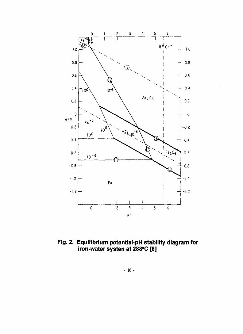
Fig. 2. Equilibrium potential-pH stability diagram foriron-water systen at 288°C [6]
- 16 -

2. Test loop £7%
loop A ^ rt # «.^7f ^ ^ * V loop
test loopl
G-i/B contents, dissolved oxygen, hydrogen concen-
trations, pH)^- «V1-J1 ol -g-eJI-g- ^ ^ ai^J- pump^. 7f<a-5>^ ^ ^ ^ 7 f ^ ^
. ^ 7$/$ 7V171 (regenerative heater) ^ <mi7ll- f-Sfl ^
] ^ O ] i-o^ ^ ^ autoclaves.
-B: autoclave ^ ^ - # f-sfl ^fl^ 7}%7)& 7)& *
adjustable relief valvel- f-s><^ ^-"y-^ ^ -fr^^-i- 7 ^ ufl
- relief valve^ wfl-
- recirculation
^•^1-t refreshing(or once-through)
7}-
relief v a l v e l - f-«fl ^ | ^ v e n t i n g ^ ?\ y£
hydrogen overpressure
- 17 -

RuptureDisk
Vent Valve
Drain316 SS
Autoclave
00
DigitalPressureTransducer
CD
Test Solution : 2ppm Li + lOOOppm BTest Condition : 300°C /1500psi, 35ccH2 STP/kg H2O, O2<5ppbTest Specimen : Hardfacing Materials for Valves in PWR
Vent
Heater
RegenerativePreheater Heater
PressureGauge
High PressureMeteringPump
T/C
CoolingWater In
CoolingWater Out
RuptureDisk
AdjustableRelief Valve
Filter
Flow Meter
Li/BSolutionoooo
1Dissolved
OxygenMonitor
Fig. 3. Design Diagram of Primary Water Simulation Test Loop
autoclave
solution
rupture disk-i-
controlf- ^
hour meter
pumpl-
loop «
Autoclave
loop
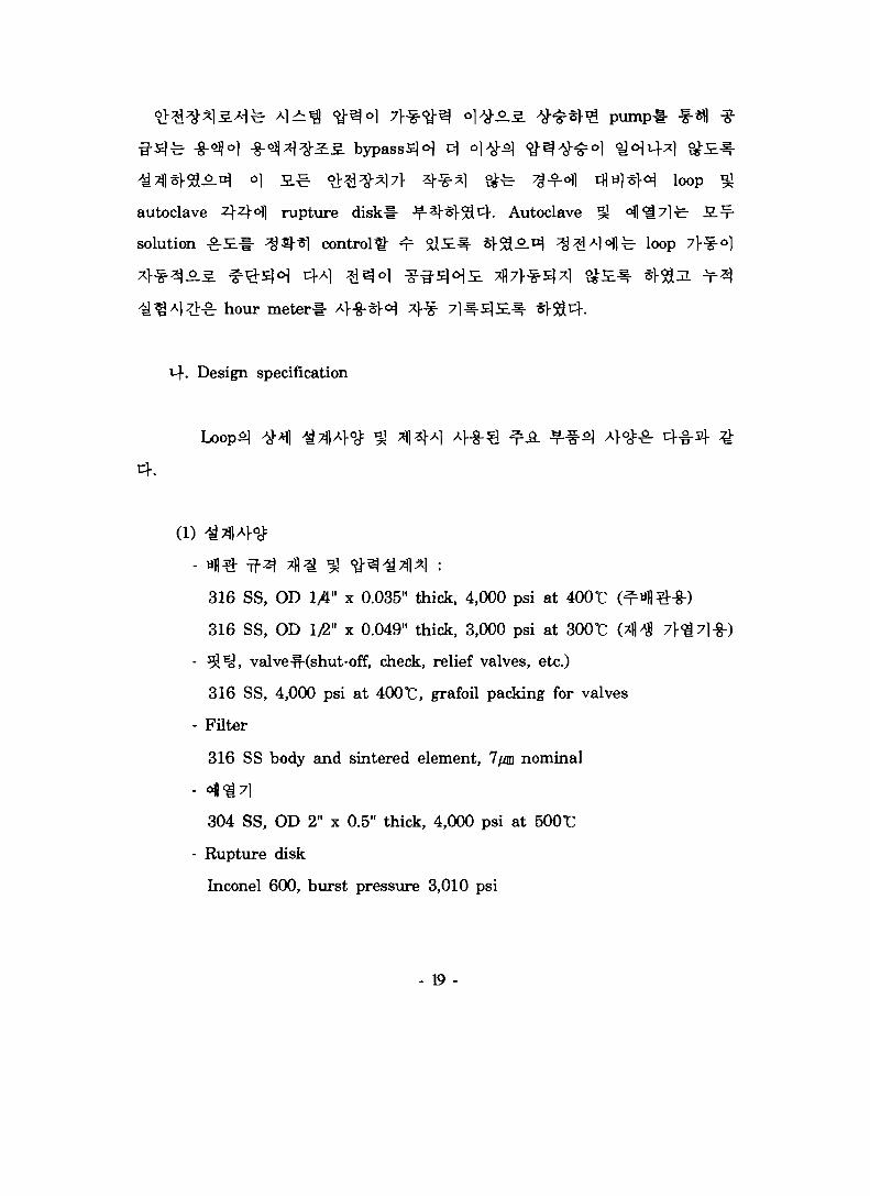
. Design specification
(l)
316 SS, OD 1/4" x 0.035" thick, 4,000 psi at 400°C
316 SS, OD 1/2" x 0.049" thick, 3,000 psi at 300TC (*
^ ^ , valve-n-(shut-off, check, relief valves, etc.)
316 SS, 4,000 psi at 400TC, grafoil packing for valves
Filter
316 SS body and sintered element, 7/m nominal
304 SS, OD 2" x 0.5" thick, 4,000 psi at 500r
Rupture disk
Inconel 600, burst pressure 3,010 psi
- 19 -

- System
3,000 psi at 400 "C, 6 liters per hour
(2)
- Autoclave
Maker : Autoclave Engineer. U.S.A.
Capacity : 1 liter bolt closure type
Material : 316 SS
Max. working condition : 3,825 psi at 343 °C
Ports : 4 on the top cover (1 for pressure gauge, 1 for solution
outlet, 1 for thermowell, 1 for future use)
4 on the bottom (1 for solution inlet, 1 for solution drain,
1 for pressure gauge, 1 for future use)
- Temperature controllers (for autoclave and preheater)
Maker and Type : Eurotherm 808 and HY-P100, PID control
(solution temperature control)
Safety device : Over temperature cut-off controllers
- High pressure metering pump
Maker : Eldex Laboratories, U.S.A.
Model and type : BBB-4, triple piston plunger type metering
pump
Capacity : 5,000 psi max., adjustable from 0 to 6 liters per hour
Material : Head of 316 SS, pistons of sapphire, check valves of
ruby balls, seals of PTFE
- 2 0 -

- Dissolved oxygen monitor
Maker : TOA Electronics, Japan
Model and type : DO-30A, membrane type
Measuring Range : from 20 ppm to 0.01 ppb O2
- Flow meter
Maker : Omega, U.S.A.
Model and type : FL-112, rotameter type
Capacity : from 0 to 2.2 liters per hour
- Solution reservoir
Material : 304 SS
Dimension : OD 300 mm x 5 mm thick x 500 mm height
Capacity : 37 liters
Test pressure rating : 5 bar
1000 mm, }*M 500 mm, ^°] 900
duraluminAS. * f l ^ framed A>-g-§H loop *}^
4<H1 ^ r ^ € loop A]
system^ zero^ ^•%•<$(autoclavevfl^-)ol ±0°C,
test loops]
-21 -

Fig. 4. Photos of primary water simulation test loopmanufactured in this project
- 2 2 -
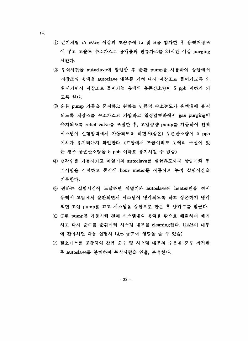
(D #7l*1*g- 17 Mfi.cm °ltf£] i ^ ^ l Li ^ B *
24^1# ) # purging
autoclave^ $<%& ^ ^ ^ pumpl- A]~g-sH
autoclave ifl^-# 7^^ 4A1 ^ ^ S .
5 p pb
pump
gas purging^]
relief valvel- ^^*V f, 3.^^^= pumpt- 7)-^-§l-^5
5 ppb 0)^5
© ^ 4 ^ * 7]-^-Ai7lJl 4 |£714 autoclavel-
lofl hour meterl-
autoclave^) heater°V-g- T>\*\
© £ £ pumpll^ Al>b^ i f l j ^ cleaning^c}. (Li/©ol
1 U/B
* autoclave
- 2 3 -
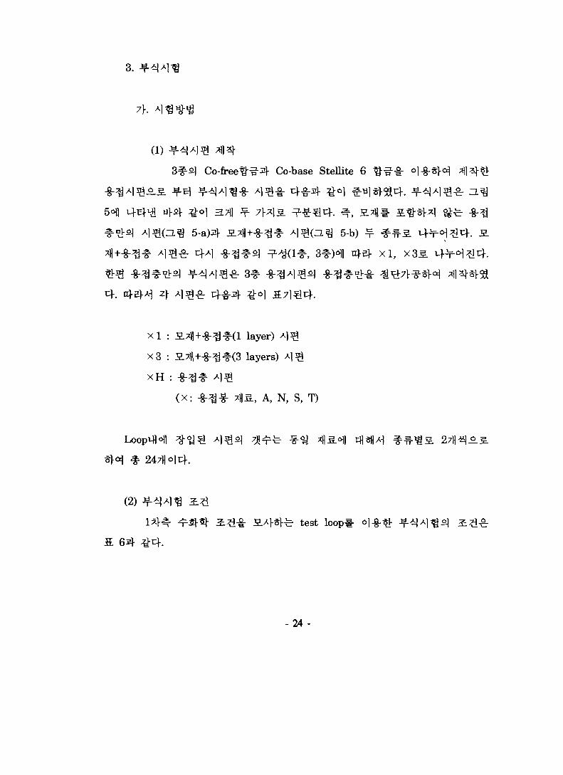
3.
(l)
Co-base Stellite 6
5-b)
x l : a.^+-§-^^(l layer) A ^
x3 : S.7fl+-g-^#(3 layers) A ] ^
XH : -g-^^ Al^
(X: -g- -f- 7])S, A, N, S, T)
# 247fl
(2) ^ - ^ A
fe test loop
-24 -
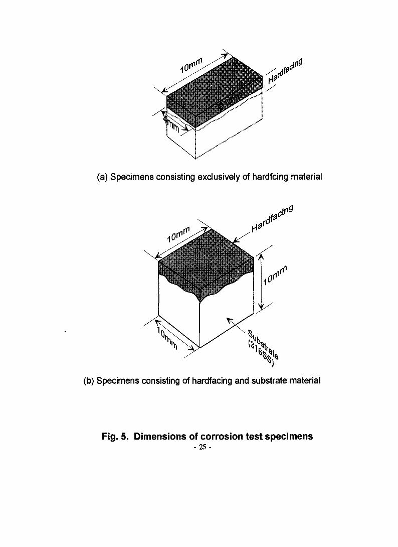
(a) Specimens consisting exclusively of hardfcing material
(b) Specimens consisting of hardfacing and substrate material
Fig. 5. Dimensions of corrosion test specimens- 25 -

Table 6. Corrosion test condition simulating the primary coolant chemistry.
Pressure(psi)
1500
Temp.
(t)
300
Flowrate
U/hr)
1.23
Water Chemistry
pH(300 °C)
-7 .0
U(ppm)
2.2
B(ppm)
1000
Dissolvedoxygen(ppb)
< 5
H2
(cc/kg)
35
1 4
Loop test
14 t
cf. n^ 64 7^
T3(Tristelle 5183)7>
-fr 2190*1
^5. 4^
71E^ , N,
1 4
Armacor
- 26 -

20
15
: Armacor-M A N1 : Nucalloy 488v&S1 : Stellite-6 + T1 : Tristelle 5183
• * • •
-G-B-
0 500 1000 1500 2000 2500 3000Time (hr)
Fig. 6. Corrosion of single layer hardfacing specimens underthe simulated primary coolant

20
to00
A3 : Armacor-M -* N3 : Nucalloy 488- S3 : Stellite-6 &T3 : Tristelle 5183
500 1000 1500 2000 2500 3000
Time (hr)
Fig. 7. Corrosion of 3-layers hardfacing specimens underthe simulated primary coolant

to
C
(D
: Armacor-M ^rNH : Nucalloy488oSH : Stellite-6 +TH : Tristelle 5183
500 1000 1500 2000
Time (hr)2500 3000
Fig. 8. Corrosion of exclusive hardfacing layer underthe simulated primary coolant

SteUite ^ t ^ 3-f ° 1 ^ ^^^V^l =?•
3:71
Nucalloy ^ s ] Jf*l^^-^o] 7]^S] Stellite
Si/B ^--i-ol ^ 7 l nfl -otf ^ ^ ^ ^ nickel siUcide^l
^=-y-Al7lfe j l Si 3)n]-ol
sums].TristeUe ^-g-S]
Tristelle 5183^ 7l^] ^A>tV fl-^-S^* ?Jfe EB 5183
71*1
Tristelle
- 3 0 -

HAZ(Heat Attected Zone),
&
Table 7. Electrolytic polishing condition for various weld metal
^^^SolutionMate r . ^ \ .
AlA3
Nl
N3
SIS3
TlT3
Oxalic acid
5%, 3V, 3 - 5 sec5%, 3V, 3 - 5 sec
10%, 3V, 3 sec
10%, 3V, 2 sec10%, 3V, 2 sec
10%, 6V, 15 sec
Others
Nital 10%, 3V, 12 sec
Nital 10%, 4V, 10 sec
7\. A
Armacor M
- 31 -

a y
b
Fig. 9. Microstructure of weld deposited layer(Armacor-M, 3 Layers)
- 32 -
phase7}-
A} SEMAS. 3}-^^- ^ r # ^ ^ c K n ^ 10
1 secondary phased
10-b).
secondary phases.^ Fe-Cr at-g- D, Cr2B, Fe2B 5J
Fe3C f l S ^-^sjfe ^ A S S.ol^ «)- 91°-^, ^ ^ ^ ] secondary phased Cr
3\- Bo]
M-. N
Ni-base ^-g-^1 NucaUoy 488^1 5§^-, ^ r ^ l ^ ^ ^ ^^-3}. dendrite
l ^ ^ i £ ^ ^ ^ ^ 3 ] ^ - ^.o|ji ^^(ZL^ 11 # i ) . ^-*) Ni
71 ] i ^ Al-ojofl NigSi, NisB f A S
HAZ
- 3 3 -

b
*S* 1
" - - ' A* * '«£%
^ A
Fig. 10. SEM fractography showing the different morphologyof weld deposited layer (Armacor-M, 3 Layers)
- 34 -

a ' , • *
"•V . ' "•
{
b , , / r
Fig. 11. Microstructure of weld deposited layer(Nucalioy 488, 1 Layer)
- 35 -

K s
125] P J ^ ^ Stellite
£r fee ^ 2 ^ austenite ^-^1 Co-Cr^
H ^ r Cr ^ ^ I - V M T C S ) ^ W ^ ^ - # ( 1 ^ 0 ^ ^
[10]. i^Aj-^lAS. ^^>7l l ^-g-a} s]^l ^ z i ^o.^- , ^ 100-200 m
HAZ7f §
. T
Fe-base f-g-^ o| ^ ^ ( a ^ 13 ^-3:) ° H Nucalloy
austenite^ 7]*}^z\o]v\; 7\*}2L^ Aj-olofl^ Fe-base
Nb
HAZ
2.
^ ^ ^ r micro-Vickers 7JSL711- A>-g-§>< bad 50
(Hv50)
- 36 -
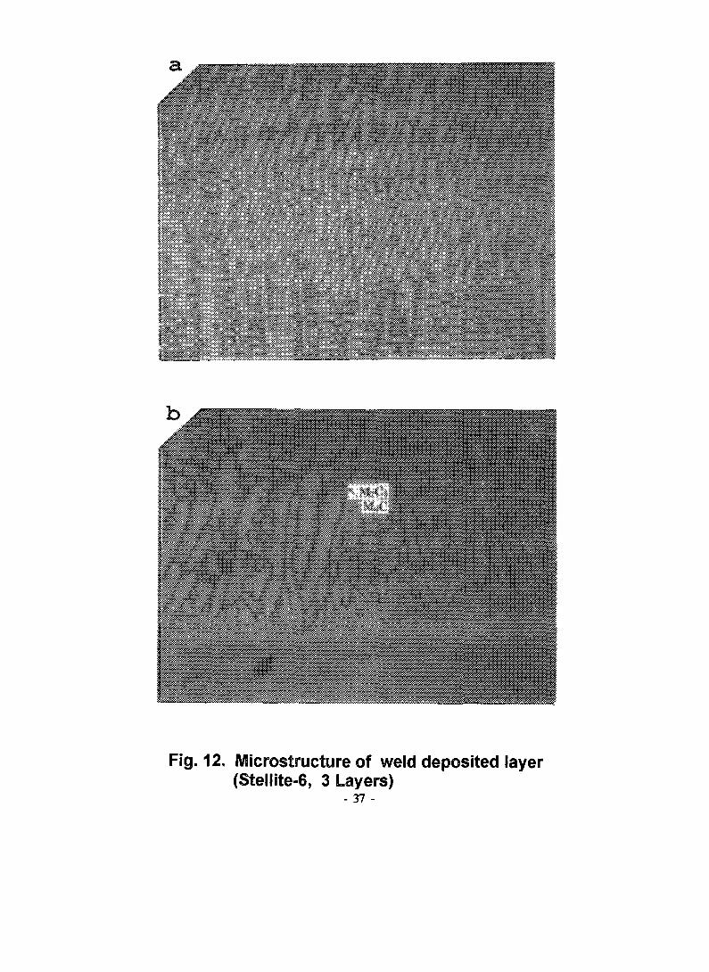
a
V M M W SV
Fig. 12, Microstructure of weld deposited layer(Stellite-6, 3 Layers)
- 37 -

* v # # *
Fig. 13. Wiierostructure of weld deposited layer(Tristelle 5183, 3 Layers)
- 38 -

or 3-layers)ofl
41 3 layer
sl 1 layer
^ 200
1541 . o]
Nucalloy
3 layers(H^ 16
^ 630
1 «B ^ 418
Stellite^
Armacorfi]
^s.41 n
400°C
3.7])
530^£S. 17
3 layer
NucalloyS]
StelliteS]
Stellite
3.7%
1. "JU-
- 39 -

o10
ICOX
1 2 3 4 5 6 7 8 9 10 11 12 13 14 15 16 17 18
Position
Fig. 14. Macrosection and hardness in the cross section( Substrate - 316SS, TIG welding)

600
o1 0 500
CD- 1
vah
COCOCDC
T5i_
CDI
400
300
200
100
0
A1 : Armacor-MS1 : Stellite-6
N1 : Nucalloy 488T1 : Tristelle 5183
Hardfacing materials
Fig. 15. Hardness of weld deposit for various hardfacingmaterials (substrate - 316SS)

A3 N3 S3 T3
to
cS
>s v
alue
Ml
CDP
700
600
500
400
300
200
100
Hardfacing materials
Fig. 16. Hardness of 3-layers weld deposit for varioushardfacing materials (substrate - 316SS)

>
CO
c"ECO
700
600
500
400
300
200
100
0
/
/
1
532<rf&38ggg883£8SS3i£8
3
436
1
: Single Iayer
628^ ^ ^ ^
x"vr ":.....
395
21:3
492Mmmm.
465
layers
451
540
/
/
Armacor Nucalloy Stellite TristelleM 488 6 5183
Fig. 17. Variations of hardness with weld deposited layers

^( reac tor coolant system)^ 3
.l- EPRI -f<Hl S|«fl *1H£U Xl7)1 f-JE.
high-Co
3J^-f 7lGapping) ^ 4 :
resurfacing)^ «l£^«fl tfl*> ^7>£ S^-s]cHo> *Vcf. PWR
w.°flAi high-Co t^-° l ^ l*>fe S ^ ^ ^ -g-l-4 25-50 rag/dm!
high-Co ^-g-ol xH§}fe >g^ O.5. L f ^ l ^ ] ^51 S ^ ^ . HOV
^S.(effective cobalt release rate)
5.
»Jw.(check
- 44 -

Table 8. Comparison of cobalt wear rates in various type of valvesmeasured using two different methods.
Valve Type
Gate
Swing Check
Globe
Spray
Butterfly
Calculation
% Area inContact
12
3
1
17
3
Assumed CoInput (mdm)
25 - 50
25 - 50
25 - 50
25 - 50
25 - 50
Effective CoWear Rates
(mdm)
3.0 - 6.0
0.75 - 1.5
0.25 - 0.50
4.25 - 8.5
0.75 - 1.5
MeasuredEffective CoWear Rates
(mdm)
1.0 -2.0
4.5 - 8.0
-
-
-
J± Hiitglove valve), rtsefl °] HJ«.(spray valve)
fw.(butterfly
7 H
(residual heat removal system)^: ^^> 1-2 7fl-fi - 7J-:§-5]7] °1
HJw.0ift check valve)5f 3 ] ^ Mjw.(piston check valve)^
z\7$o) 4-8: «Jw.<H)Advent/drain valve) =L
high-Co
71-
-45 -

Identify valves that contactRCS
Estimate Co release to RCSfrom maintenance records
and EPRI reports
Prioritize candidatevalves for replacement
(i.e., valve is to be refurbished)no
yes
Identify candidate valves Ifor replacement or I
Identify valves design, operatingconditions, duty cycle
yesJustify continued use
of Co-base HF
RefertoNP-3220to minimize Co release
Fig. 18. Schematic for Implementing a Cobalt Reduction Program-46 -

Gate, globe orother valve
Isolatingcontrol valve
Check valveNon-isolationcontrol valve
Calculate(disc/seat)contact stress(a) Pivot bushing Seat
Select HighPerformance I
Select Fe-orNi-base HF
Eliminate HF
Justifycontinued use of
Co-base HF
Do notchangeHF/trim Perform 50.59
determination if
Identify valve vendor orservice organization thatcan supply selected HF
Fig. 18. (continued)
- 47 -

7\ . t
I = Io exp [ -(t/1.60) ]
, I : t
t : ^1?> (V!)
t =
Co-6051 52%7>
exp [ -(5/7.60) ] = 0.52 Io
Co-602)-
Table 9. Decrease of Co-60 and radiation dosewith cobalt source reduction.
i
Year
15101520
% Co-60Remaining
885227147
% DoseRemaining
9164453630
benefit) ^ -^
«]-§-
. 3.
(cost/
- 48 -

Table 10. Priority of valves for cobalt alloy replacement.
Rank
1
2
3
4
5
6
7
Type
Globe-FlowControl
Spray
Check
Check
Gate
Globe
All Types
System-Location
CVCS - Downstream ofdemineralizer
RCS - Pressurizer
CVCS - Downstreamof demineralizer
RCS - Safety InjectionSystem Interface
RCS & CVCS Down-stream ofdemineralizer
CVCS - Before demi-neralizer, RHRS, BoronInjection, SamplingSystem
Remarks
Used in charging line -subject to high wear.
Cobalt can indirectly enterprimary coolant.Used in charging line ;Check valves show highwear.Check valves show highwear plus relatively largearea for corrosion.
Gate valves show moderatewear and corrosion.
Globe valves estimated toshow moderate wear andcorrosion.
Most cobalt removed bydemineralizer. System usedinfrequently. Small amountof cobalt hardfacing used.
14. ^ Co ^ Co-free
CO
. S. l l^r
Co Co-free f"g--^
Co
15 % j y H ,
Stellite 61- «]^-*M Stellite 6B, StelUte 21 ^ ^ Stellite^]
Haynes 25, Haynes 36, Co-156, ZL^\3L Co-12 ^ -f
Stellite 6 ^ CabotAH>H A>4-*>OL &fe Co-Cr-C-W ^-^s] ^ A l 1930^
- 49 -

Table 11. Chemical composition of various hardfacing alloys.
Alloy
Aus. SS410 SS420 SS440C SS
17-4 PH
Incooel 600Inconel 625
Stellite 6Stellite 6BStellite 21Haynes 25Haynes 36Co - 156Co - 12Cst Mtls 6
Haynes 711Haynes 716Haynes N6RHDUGTristelle 1Tristelle 2
- NickelCobex 545Cobex 547Colmonoy 4Colmonoy 5Colmonoy 6Colmonoy 74Colmonoy 84Deloro 40Deloro 50EutroloyLurgi 4500TribaloyT700
Cr
18-2012
13.617
16.2
14-1720-23
33
302720
18.52930
28
Ni Fe Co c MnBase Material Used as
8-10.5--- -- -
4
72 min58 min
bal
baJ
bal
bal
bal
6-1015 max
.12-.18--- -
-
02-.0B.05-.10
.08 max.11.36.07
.05
.15 max
.10 max
Cobalt - Based33
2.810103
2.5
3
Low27
26
29
283035
Based27.527.5
10
11513.510.4297.5122831
15.5
bal
bal
bal
381010
33- -32
0.752.5
3
5553
6550
56balbal
bal
Cobalt (12329
3
bal
bal
bal
1211
3IIS1212
1.1
1.1
.25
.07
.41.6
1.4
1.2
to 152.7
1.11.1
1.512
2.46.39
1 max
.68
- -
Cu W Si BTrim Material—--—--4.3
.5
-----------
--.44.38
1 max
.47
- -
Hardfacing Alloys--2--1.5- -1
.25
.5
• %)1
1
1--- -- -
- -
- -- -----——
64.5- -15
154.58
4
- -
2- -1
--1.21.7
IS
------—---
--------.03- -
- -
- -
Hardfacing Alloys—
------—
33.5
2
2.5--- -
Cobalt Free « 1 %) Hardfacing
bal
bal
bal
79
74balbalbalbal
bal
bal
bal
8
7
2.54.254.752.51.51.53.513
-
- -- -—--- -- ------ -.2—
-
1.3
1.5
.45
.65
.75
.481.1.35.6
1.7
1.3
.08
1
1--- -- -- -—--- -- -- -
- -
—--------—-----------
7
7- -
- -
—
47.5- -- -.29
- -
11.51.5- -55
- -
.5
.6- ---- -
Alloys
1.5
1.5
2.253.754.252.51.953.53.51
2.1
3.4
----- -2.53
2.11.31.72.11.1
Mo
------
.75 max
- -
--
--
1.5
5- -- -11
1
8
3
5.54--- -
7
7- -
- -
- -
- -- -
- -- -
8- -
32.5
Other
--------
Cb+Ta.35
- -
- -
- -
--
----
--
--
- -
- -- -
- -
- -
Al-1.5Note 1
- -
- -
- -
- -- -
- -- -
- -
- -
Note 2
- Iron BasedAntinit DUR300CeoiumCenium Z 20EB5183Event 50NITRONIC60NOREM BlNOREM B4RHDICSKWAM
21
24-2827
2025
16.5
24.724.828
17.5
8
30-341810- -
8.5
4.026.05- -- -
bal
bal
balbal
bal
bal
balbalbal
bal
.3———
—
————
.12
1-7
.32
2.5
.10 max
1.031.051.5.2
6.5
3- -- -< 1
8
7.7912--.55
--————-
———
3-52- -- -
—
--- -1.5- -
5
2- -5
< .5
4
3.115.171.5- -
.9- -- -- -
—
--- -- -- -
- -
6-8--- -3.2
- -
1.991.961.51.1
—
Note 3< 5
Nb-8V-.5
N-.14
N-.26N-.23
- -- -
Note I : Al-1.5, V-4, 2 : Co*Fe - 3 max, 3 : Nb/Ta-3, Zr-3, V-3
- 5 0 -

Haynesofl
5]JL $X^- ^ Co tfg-£ 1-15 % S ^ S . ^ i l - fl-fr^- ^ - 2 . 5 . , Haynes
711, Haynes 716, Haynes N6 ^2] i^5g^| --g-i*}- RHDIIG, Tristelle 1,
ZL Tristelle 2 # 3 1^) ^-g-o] o}7H ^*V4. Co-free ^-^-^r 2 f £ Q
Z,^°} 1 % oj^o] ^ g - nj.^ t^ j o]i- tg-^-^. 4 A ] q^Tl) ^-^-ui). ^^ i
A5. £-ff-€t}. q^Tfl ^-^-ofl^ Deloro-CabotAl-oflAi 7fl -*}- Deloro
Deloro 50^- yl^^><^ Cobex 545, Cobex 547, Colmonoy 4, Colmonoy 5,
Eutroloy ^°] $X^. ^^1 ^^^ l^Tilf- 3.^E. ^^^\ m}4*L3- 7\^ &^
.B\s\JL 9X^r ^±^*\, °l^-s] EPRI^I- AMAXolH 7^$: NOREM,
Thyssen EdelstahlwerkeAHl*\ #& Everit 50, i^ iSe lo] . BOHLER
SchweisstechikAj-5] Antinit DUR 300, 3.B\5L E.^-^ CEA^- LAMEF7} ^
•§• 7fl -*V CENIUM ^-g-o) $|4. J3.3JL n^ofl Stoody Deloro
EB 51834, NITRONIC 60, RHDIC ^o] Co-free
^ | 1 ^ j ^ f e . JT Co
Co ^•^•*«>1
(1) o]-s.(wear) ^ ^ - y [14-20]
^- -£-£}-*1l-.5-(adhesive wear), ^ ^(erosion), ^^pfS.(abrasive wear),
- 51 -

S.(surface fatigue) ^o] o^tfl *]%• <$qv\3.Q S.#Z\3,T= ^ 3 »£*.<)}*] 3.
-f°H >M-8-5)fc ^ ^ G^Ht «fl^ galling
^ , -fr*H^ -^:i-0] e*ti*m*l e •B-^^V ^^|*>fe ^-^7lofl^ 3]-§-Sl*r 711
^ ^-(bonding)
( transfer)^ ^Sfl <y<H14D],
., ^-«1 gallingofl
galling^]
« galling
5-8 ksi ^ £ ^ £ £ ^ ^§1-^41/H Colmonoy 84, Colmonoy 74, Deloro
40, Antinit DUR 300, Everit 50 •§• Co-free ^-^-1-^r
Co-free ^ ^
f1^:^^^ ^^*V^(15 ksi)oflAi Colmonoy 84, Deloro 40, RHDIC,
Tribaloy T-700, Vertex 4776 ^-$\ Co-free ^^^ -^1 -^ r J ! CO
- 52 -

3L Co ^ ^ A ] ^ t n$ 71S]
15 ksi °]SHH *)-§•£] t tfl^-g-S] 1-M. ^ ^ Co-free ^-g-^
# £ 3 1 7 ^ ^ ^#*HK15 ksi ^1^-)^- ^ -^ S^oflAi EB 5183, Everit
50, NOREM 01^1- 04, Tristelle 14 2 •§•£] Co-free ^ ^i-Co ^^^-g-l-fil °>
a m ^ O ] JI-CO ^-^-4 71 °) *s-<£tiW. rtt^M o l s l^ x-j-Co ^ Co-free ^-^-^
^ 1 ^ JL-CO t ^ # °I#S. H ll aj-g-«>^i 53 ]
NOREM, EB 5183, NITRONIC 60, Tristelle 1,
2 -§- JH-g-^HA-] galling^)-
1 ^ fly^ ^ ] H 5i ^ % ) ^ Deloro
AECL -f-^
(1+)
1) J l ^ r > -ff- - (High Velocity Single Phase Flow)
tftf -8- 1 il-O] Sjfe. ^-ffe ^ - i f ^ 6
. Deloro 402)- 50^ water jet ^ l - g t H ^ Stellite 6<1 «l«fl 2.5
3ufl ^ £ ^ T f l ^ ^ ^ 0 ! 3711 ^Bf^cf. Everit 50^ Antinit DUR 300^-
Stellite
- 53 -
20
2)
4 Tristelle 2fe SteUite
Tristelle 14 EB 5183^ Stellite 6<H1 «]«« 2~3nfl
a.13 NOREM 014 04fe ^^)-^-^) ^Hv^°l Stellite 214
A ^ (308 ^^l^l^^^ofl »l«flAl*f 5«fl Jgs. ^tg-^c] a.),
fflwlEllo|^ ^^<H1A^1 NITRONIC 60^ ^Jfl-^ol Stellite 6B
2/3 i?W <J>sjt 1 4 1 - ^ ^ A i 4 300
r 3~4«H T^sj-^cl 3 ^ A S
(2) n>#7D^
3]-
-54 -

-Co t^-^r ^ *flJ3.#3 3 * H *>#3l^7}- a)-Co
i-Co 51 ^-Co t ^ # ^^«fl
^ ^ ^ l 7 l i *Vcf. Deloro ^
SteUiteSl pf#^]^5}- 71^
SteUite 6 ^ 7]^ «1^5>uj- n^-o]]Ai^ Stellite
^ - i : 347 ^E)l?l
StelHte 6 7]Slfi] ^ 3 1 ^r Slt^^l l ^ ^ l ^ . NITRONIC 60S]
7} xif>}^o\]*]±r Stellite
2.
7K afl i € ^ ^ Co-free tf$ 3-fc- 3 3 [2, 21]
Co reduction program^ ^ ^ - ^ 71^5] Co-base
Stellite tf^sl ^ A ^-^ofl ^-%-t}^ -f^«l- ^ ^ ^ x-ICo/Co-free ^ - ^ - l - * 7fl
(1)
7» BWR gj PWR
1980\icfl i Vermont Yankee
(feedwater control valve)^ nfS.^-^^- ^A>«}- ^ 4 , o) ^«L7> ^ ^ 1 ^ 40 g
-55 -

^r-ir RockweU 7 j £ < 50^ 440 C ^ l ^ i N ) ^ 7o>o.S
StelliteSLt} nK5.^*J-^°l #XI v+E}-q-o.s>«i, throttling^ flow!
e} cavitation 41 £ ^ JlL^s] # # ^-^lJlf-(single phase flow)
^J^ofl ^«.Vcf^ ^Jol |^-^ ^ ^ . ^ , o]& cavitation 4
5a* 41 safe- ^-y-^^. ^ 7 ^ ^ I J I sa^-. l ^ , 440 c ^
Q.3. #0]
BJW-^^-SAi iBflo]Bl]>; 7ov (440 C, 316, 17-4 PH
Stellitel-
*) Stellite
i4) Loop test
ZL% 19^1 PWRofl tfltl- EPRI^ %%MM «: ^r 5Ufe y
80\£tfl 2:W> ic -a^ fuel spacer grid# 9l3."i ^^^^ Zircaloy-45.
fe Co-base
Co-base
71 ^*!- 7l^7fl^-sl ^ ^ r ^ - S . galling ^ ^ - ^ 0 } -f^*V 3 ^ ^ ^Tfl Co-free ^•^•
(NOREM, Everit 50, EB 5183)3}- Co-base Stellite ^-^-S- ^ j ^ s : } ^ BWR4
-56 -

% Replacement Components using Cobalt Free Materials
•
to
Oo3o<D
1
o00
o s00
00
oo9>9oo
OCXXXXII(/}
QH
o-
o
<03.
(D
i2]Q
<01
(A
E35"6o

PWR AECL
Sheridan Park Engineering Laboratory ^ « . A ] ^ loop
9705), PWR^ 3-f 19003] full stroke cycle
Zl is]-, ^ J i ^ - ^ S.Sf-7} -"y- AV, ^f^^AK profilometry
< Ai Stellite 6 M.4 -f^^-ol *g^s|$il^. ^ 3 ^ ^ QA Co-free
Stellite
Everit 50
. ^-*1 NOREM 0 4 ^ EB 5183 f
Stellite^ll w
StelUte 6^ tfl*||7||fi.S>H 4-8-1 T1 Slfe ^ - ^
Si
l - ^ Co reduction program^
o.^, Co-free tf-
. S. 12fe Co-free -g
(2)
Co-free loop
SU*H-H Deloro 40, 5 0 ^ Colmonoy 4, 5, 6 ^ - g ^ A>-g-o]
j-e -A Ontario Hydro ^ S j A } ^ Colmonoy 5/Deloro 504-
double disc gate ^ check ! « . 257fl ol^-fi- Anchor-DarlingO.5. Jf
- 58 -

Table 12. Specific details about the Co removal programs in the U.S. utilities and plant.Utility
Boston Edison
ConsolidatedEdison
Duke PowerCompany
Duke PowerCompanyEntergy
Florida Power Co.
General PublicUtilities
Houston Lightingand Power
Illinois Power
Plant
Pilgrim
Indian Pt.2
Catawba
Oconee 1,2,3
Grand Gulf
Crystal River
Oyster Creek
South TexasProject
Clinton
Type
GE-BWR
W-PWR
W-PWR
B&W-PWR
GE-BWR
B&W-PWR
GE-BWR
W-PWR
GE-BWR
Demonstration Testing• 1970^cfl -g- 2i^»i a. trim : Stellite -> 420SS5. 51*11• 3 e # « r check € « . t\^3L : Deloro 50 43- Ar-§-• 1994V£, 12*1*1 # ^ r gate 'S*.(non-safety-related) 3^ ^ * H 1 ^ : NOREM *}--§-• 4 ^ 1 2^6.71 safety-reated BJM. : Co-free ^ ^-§-•3*1*1, 1500# AOR globe »J«. 27fl : 17-4 PH disc seat•3*1*1, gate *I*L 47fl : Deloro 40/50 seat and stem•3*1*1, 1500# Y-pattern globe "JiL 37fl : NOREM Bl disc seat (CVCS)
•8*1*1, 150# SS globe "fi-M. (safety-related isolation valve)-Colmonoy body, disc seat
• 1, 1.5, 2*1*1, 1700# double disc gate BJ«- : SS body, Colmonoy disc Stellite seat -
• 1995V1 Recirculation pump discharge flex-wedge gate HJ«. 27fl : NOREM *}-%• <$$• 1*1*1, modulating globe decay heat system 1S.M_ 27H : Nitronic 50/60• 1/2*1*1, isolation gate l i 27fl : Delore 40/50• 1989\i 6*1*1, -a-^ bypass 2 : ^ ^ « . 27fl : 17-4 PH body seat, plug-440C• €*M*1 ?F#^sl* ^ ^ ^*J• 10*1*1, 1500# ^ - ^ ^ ^ «J«. : CrNi body seat, 440C plug-10\i 7VS-• 14*1*1, ^^-^r MJ«- 2711 (MOV) : Colmonoy 5 seat, disc - 4*d 7f§-•10*1*1, gate «J«.(MOV, tilA1^47flf-) 67fl : SA240-347W/NiCr, body seat,
SA182-316L W/CoCr disc seat - 3Vl A^•2*1*1, SS double disc gate H i i : SA 351-CF8M body, NOREM 01 disc, NOREM
04 seat ring•8*1*1, swing check 13±L : Colmonoy disc (safety-related)• 10*1*1, - 3 - ^ £ $ - 8 - 3 ^ MJ a. : 316SS seat•24*1*1, feed pump discharge check valve 47fl : Stellite disc IB.*fl °fl^

Table 12. (Continued)Utility
New York PowerAuthority
Niagara Mohawk
PennsylvaniaPower and LightSouthern Nuclear
Operating Co.Tennessee Valley
AuthorityUnion ElectricYankee Atomic
Electric
Plant
J.A. FitzpatrickNPP
Nine Mile Point
SusquehannaSES.
Farley
Sequoyah
Callaway
Vermont Yankee
Type
GE-BWR
GE-BWR
GE-BWR
W-PWR
W-PWR
W-PWR
GE-BWR
Demonstration Testing• 50711 <>]•$• safety-related/non-safety-related HiL : Co-free ^ - - ^ . S - S*ti• S ^ l 3/4e,]tf : NiCr(Colmonoy-DeIoro 50) >M-8-• 10*1*1, gate, double disc »J«. 2?fl : RHR system ^-§-• 10*1*1, globe H-M- 27fl : RHR system•8*1*1, check u J i i 27fl : RCIC system• 10*1*1 X2, 16*1*1 X2, double disc gate H : HPCI system•6*1*1, double disc gate i S l 2A '• clean-up system• 3*1*1, double disc gate 1 1 27fl : ^7) 71 f-• 18*1*1, swing check «!«. : ^ ^ ^ 1 1 -• m 4^• globe 11*1 1507)1 5L 1 Tfl^ : PH SS•8*1*1, globe >i«L(MOV) 27fl (safety-related) : Stellife 6 body, Deloro 40/50 disc
seat and guide• 18*1*1, ^ - f r ^ ^ ^ H : 400SS disk stack, 400SS/17-4 PH plug• 10*1*1, emergency condenser return system (safety-related) : SA 351 CF8M
body and disc seat, A582 Gr. 416 Nitride bushing
•24*1*1, gate "JiKMOV, safety-related) : Hastelloy body guide-4'd 7Y%-
• CVCS UJ o. 6711 : Colmonoy or Deloro 4
• 8*1*1, check HJ «. 47fl : NiCr body and disc seat• CVCS-§- m : NOREM• 1.5*1*1, globe H J l 27H(safety-related, CVCS) : NOREM body and disc seat
• ^ - f r ^ ^ 1 1 2711 : 440C SS

check «8H.3 3-f 1.5-10" , gate «J«.Sj ^ - f 1.5-12"
Ontario Hydro's Pickering B tfKgiS] 4 - 8 Jl7HH<>] Stellite tfl-tl Co-free
4fe 5 13^- ^ 4 . o ]§ ^-^.o] ^ 4 ^ ^ ^ . 1983^ ^ ^
Ontario Hydro
^.S. ^ i 5Ui=h
^ o ) ^ - ^ €
. M , AECL^r
Stellite!-
£ Deloro 40, 50 ^
Ontario HydroBJW-
Co-base
371
Table 13. Example of Co-free alloy application inOntario Hydro's Pickering B plant.
Valves
Main primary heat transportsystem (PHTS) in-line gateand check valves
Moderator and auxiliary D2Osystem gate, check and globevalve
Vent and drain globe valve
(< 2")
D2O system control valve
Material
Deloro 40, 50
Deloro 40, 50
Colmonoy 4, 5
17-4 PH,AISI 440C SS
(3)
Co-base , o)f
- 61 -

ABB3
Co-base tf^-g-
Co . 3 314 ^
cl-ft-^- Co
Co t ^
Table 14. The Swedish nuclear program for replacement of Co-based alloys
Plant Replacement of Co-base Alloys
Oskarshamn1, 2
• Unit 1 : 1989^ -g-n^f- UJ«- M%) - Deloro 50 disc, Stellite 6 seat•Hot isostatic pressure(HIP) 2465 H i L ^ s _ 1 9 8 6 ^ ^«1
•am-HIP 2465 - Ragnalloy ^ *}& : 10, 1291*]bushing, seats. Af-g-, by-pass MJ«-^1 ^-g-
Oskarshamn 3 SS , Metco 19E, HIP 2465, Citochrome ^f-g-
TVO• C i t o c h r o m e *•}•%•
7] relief ?fl-f-ifl Sulzer solenoid 1 1 : x40Crl3 ^V-g-
Forsmark 1, 2• Ball "fiiKsafety relief valve ^If-) : 1.4122 ^ 9 "• flex wedge 1=1-M. : Colmonoy 45P seat and plug
Forsmark 3 • Control, CCI MJ *L 3571] : CA-61SM, 1.4122, 316SS
Ringhals Globe : Inconel 600, 6254-g-
Ringhals 15171^ Inconel 6 0 0 ^ 625
S.S. . Stellitel-
w. 1711 •
fe Inconel 625 ^ - ^ A ^
3-4H1
t\
Inconel
- 62 -

. ASEA-ATOM^r Deloro 50^- £$ •$ • Co-free
(4)
%#} Co-free >
^•^1 Event 50(^-1]), Antinit DUR 300 (i^MBlo}), Cenium Z20 (*#£.) *§•
o)] cfl*V t ^ ^ ^ l ^ ^ - ^rsS§H 5*4. KWU#^r 3-E- Siemens*!] ^^) ^ ^ ) ^
1300 MWe # Konvoi series PWR^ ^-f, 1JI>^ 1537fl S.^- »Jw.7|- Co-free
tt°-3. cflfl]A]-g-£|Ji SU -fi. a-*lji Xi^^, ^^) Co
«B 25% o l^S. nfl^- ^o> ^ ^ - ^ Jial^oL Si^- Co #
Col: >M-g-*|-ia ^-S-^ 85% o|
Co ^-^- ifl«||S. Srol ol^-<H^i4. H B J J ! ^Afl^AS. Inconel
Stellite ^ A}**]
gate ^«.<fl ^^s l©!
-8: Everit 50, 50 SO, Antinit DUR 300, Cenium Z20, Cr7oV
20% ol*}5. « i ^ * l #<H 1 - i , sg-a- ORE71- 15%
i) ^ 4 ^ Ml Jg-3" ^sfl Co-60 ^£ fe - 1 order
ii) ^r^divfl <*}5i ^-flofl>H^ Co-60<H1 ^ ^ ^I^Ai^ol 1/10-1/505.
5 f t * .iii) ^z^ f l i f l Co-60 ^ £ 4 Co-60<>11
- 63 -

7j]7> $X
t!-^ Grondhe NPP (1,300 MWE, PWR)^ <g-3-g-7liflS] Co
S#-g- Co-free
pH £ # 7 l # , n
171- 29 man-rem/t)lant<Hl
(5)
^^-^r ^ S BWR Q#$] Cot^" ^ ^ 1 1 - ^^«l i SW. Co-free ^
sf l^^ « J H . 5 . A ^ 4, 6, 20 *]^1S] gate BJw.^- 3/4^^1 globe «jw. J§.O]
t\. Gate «jy. ^-^11^1^ Nucalloy 453, disc<Hl^ Nucalloy 488^1 A>-g-s|^ji,
globe BJ«.^ ^S^- ^ - ^ 1 ^ disc seaH Nucalloy 453^- ^-§-*>^4. <&*?• gate
(6) £ £ H
^ ^ H ^ Loviisa
w.1- Co-free ^flS.5. JE^l^^cf. ^ H 4-8-€ ^ ^ - ^ Bohler Fox
«jy.fe #-8:
Co-free
- 64 -

Table 15. Vendor cobalt-rree valve offerings
Vendor
Anchor/Darling
Atwood-Morrill
BW/1P
Control Components
Conval
Edward Valves
Cobalt-FreeHardfac ings/Trim
Colmonoy 5
Deloro 50
NOREM
Type 309 SS
TristelleEB 5183Colmonoy
Colmonoy
Nitronic 50/60
Type 616 SS
Valve Function
isolation
non-return
isolationnon-return checknon-return checkmodulating/throttle
isolationnon-returnmodulating/throttlingpressure relief
isolationnon-return
Valve Type
gate, globe
swing and lift check
swing check
gate, globe, diaphragmlift and swing checktilt discglobe
check
globe
lift and stop check
globelift check
Valve Size
0.75" - 24" ; 150 - 1700#
0.75" - 24" ; 150 - 1700#
3" - 12" ; 150 - 900#
3" - 56" ; 150 - 600#
.375" - 24"150 - 2500#
.25" - 30" ; <4500#
.25" - 4" ; 900 - 4500#
.75" - 2"

Table 15. (Continued)
Vendor
Fisher Control
Newman Hattersley
Velan
Vogt Machine
Wm. Powell
Yarway
Cobalt-FreeHardfacings/Trim
Ni-Cr
Colmonoy 4/5Deloro 40/50Deloro 2265A
Deloro 40/50NOREM
AWS 5.13 R NiCrB
13% chrome
Nitronic 50 (disc)Nitronic 60 (seat)
Valve Function
isolationmodulating/throttlingpressure relief
isolationnon-return
isolationnon-returnmodulating/throttling
isolation
Valve Type
globe, butterfly, ballglobe, butterfly, ballself-contained regulators
gateglobelift check
gateglobecheck, swing check
globelift check
gate, globelift and swing checkglobe
globe
Valve Size
.5" - 36" ; various classes
.25" - 6" ; 150 - 1500#
various sizes and classes
.5" - 2" ; 150, 300, 600, 800,1500#
various sizes and classes
.5" - 2" ; 1700 - 2500#

vfl-8-
(l)
1 ) Co Reduction Program ^ Co replacement
% &2\$IA, Co-free
Stellite
seat^f disc -^-^°fl^^ erosion, cavitation £^H1 $]*}: »!*-$]
disc
Co-free
(2)
-67 -

Table 16. Status of domestic nuclear power plants.
7\] f-
X
3^X
3 ^ O• Stellite-6
3 ^ O• Stellite-6
• Stellite-64-§-
^ A €-*fl valve
• check valve• control valve
• RCS boundary iflvalve€-^]Sl^.
-
• seat^VS. - leakage
• seat, disc - erosion/
cavitation
• &#$• ^ - ^ ^-^^d
• seat VSL
-
• erosion- S^^f-S-^1 mill
• seat, disc ^r^Al- y ^ JJ 11
• °d^- lapping^f-8-
• ^.^ lapping
-
Co-free;^^-
*\&^
X
X
Co-free^"^-3-§-=3 £31^1
X
•AECL^. ^-Ei ^ ? t ^ J i «> r

Co
°11- 71^ f1 ^^l'Sw.5] ^-f, Co-free
Co-free
GTA(TIG)
TIG
cost/benefit^
1. 1 1 ^^3flfi.^ #Atb " F s . ^ ^ [22]
7f. Adhesive wear
- 69 -
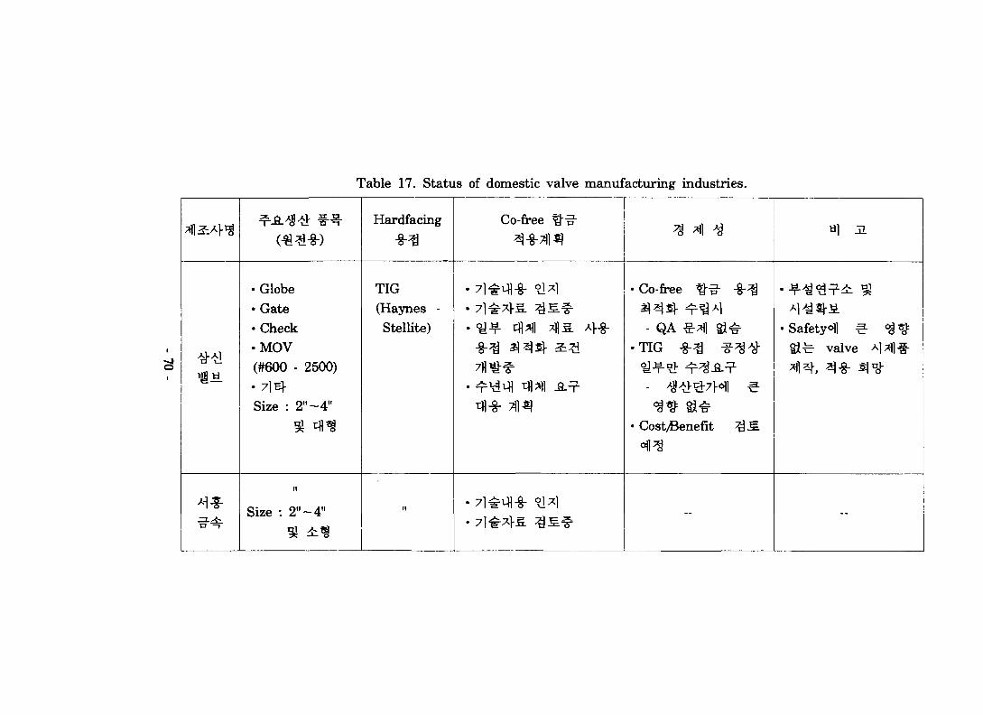
Table 17. Status of domestic valve manufacturing industries.
• Globe•Gate• Check•MOV(#600 - 2500)•7mSize : 2"~4"
Size : 2"~4"
Hardfacing
TIG(Haynes -Stellite)
Co-free ^"n"
• ^-¥- 11 1 ?fl£ A>-§-
711^"^
tfl-8- 1 ^
• Co-free ^-^- -g-^
- QA €-*fl S i ^
- ^4>3:7H1 ۥ
• Cost/Benefit ^ S .
-
,1 a
• Safety<Hl ^ ^ ^
Sife- valve Al^ll#aflXJ., aq^. i)nj-
--

74*1)7}
adhesive
Hflo]^(journal bearing),
(1)
growth), transfer particle^
t)-. #•¥•*=•
wear particle^-
cracko]
sperity junction
positive
junction growth ^^-^r
^ wear particle^-
particle^-
-71 -
jA5. cracky
•g-
transfer
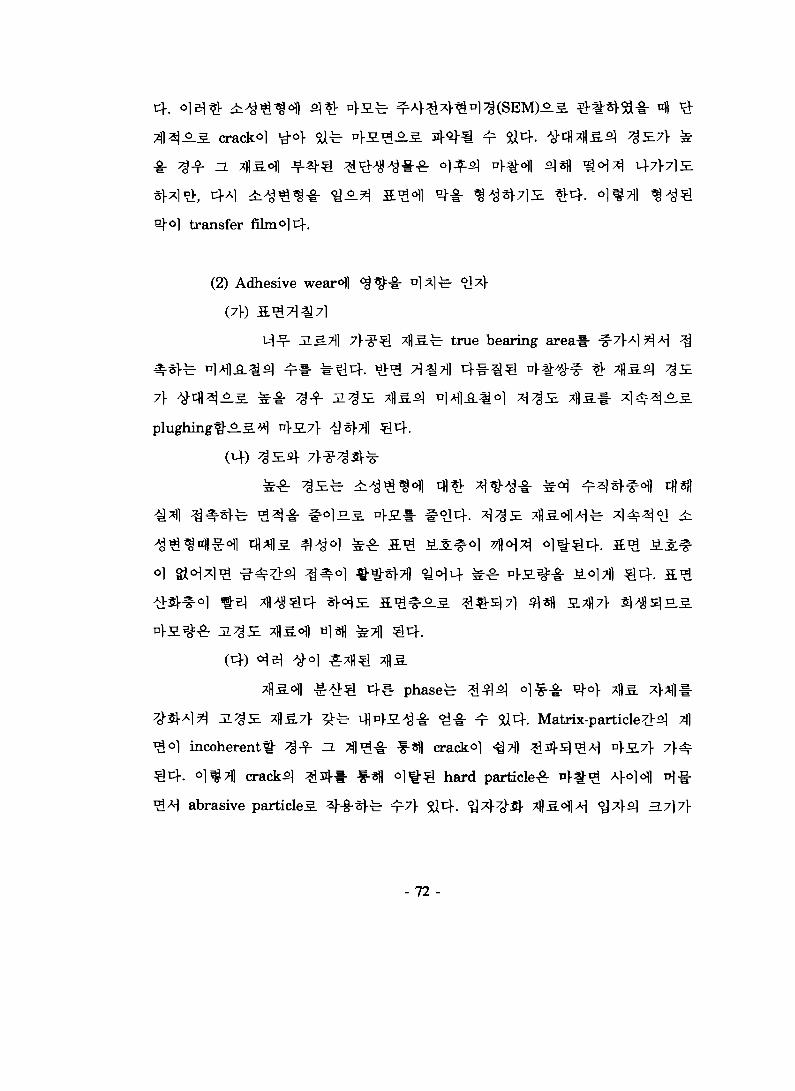
(2) Adhesive wear^l
71
e.7fl 7] -^^ ^fl .fe true bearing area*
phased ^i^^l 0 ]^^ - ^o> 45.
^-g- ^-g- ^r 5U4. Matrix-particle^s] A
incoherent^- ^ - f ZL ^l^-g- f-«l) crack^l 711 ^ 4 S ] ^ A - ^ V}S.7} 7}^-
oj^Til cracky ^sj-l- f-«fl o ] ^ ^ hard particle^ *}%# ^}o]d\] v\%
abrasive particle^. 2}-&-5>fe- ^7\ ^i^-. °^A7^ AS.^tf 'S*}^ 3.7]7\
- 72 -

bearing surfaced.
yl«fl matrix
matrixl- $ ^ 1 7 ] ^ ^-#s]x] ^ i ^ - matrix*
adhesion*
^ ^ * 7lt«£ ^ ^t)-. p f t l ^ ^Sf1^ o e] impurityl-ol
sa^s-a-
i-(-. Erosive wear
Erosion^- <Q*k7} ASS.^^ ^ l " * } ^ ^ -S::§-O1)M^]5. abrasion-g-
abrasion^ ^ A ? l 7 l i Z\JL, IL^A
fatigue, brittle fracture, melting* ^ A
4 a ^ ^ ^ . S °]<H^7l ^Mlfe incubation
. Incubation time^]
- 7 3 -

Incubation time^r W ^ l ^#°il ^«fl crack^
o] 711S. ^ ^ 5 . v+El-ul-xlfe &fe 7l#°lT}. O]B\^. incubation time-8:
£.3. nfl-f # 4 . Erosion^ 7 ^ ^ H 1 ^
(1) Erosion^]
abrasive
erosion-i: ductile mode erosion °]e|- S>J1 €• "y^l-^5] erosionions-s-brittle mode erosion0] 5}
^ ^ 7 1 7 H ^-^€r>^ 7fl£.ofl fatigue* "^-5.
20 nvfe o |^5l
Mfe fracture-fi- -
-dm/tit = kvn
m :
t :
k :
v :
n :
- 7 4 -

^r 2-3
100-1000
fracture7l-
^ 37lofl o|-e|-
brittle
effiency
particleSLcf ^ 7 ^ ^ r particle-ar
°.3. erosion^ 7^?\ ^ ^-cf. 3. o g ^ ^
°.5. abrasionofl s]*V ^ ^ - ^ . c } ^ brittle
o)o\) nj-e}- 4 7%g.S>\ erosion resistance^- ^1-^7*1-
5]«]- ductile mode erosion<HH
ductile
^ collision efficiency(#
xf-ol x+ -(turbulent)
collision
collision efficiency?]-
(2) erosion
P = p • V, • V
P :
- 7 5 -

Vs :
V=250
V:
MPa7>
. 3 mm
(3) Cavitation wear
-&-«fl3E.
-5}-7-
Cavitation
1) £3
Cavitaion-8r
Sfl nl.J2.7f
2)
cavitation wearS.*), 7}
o| 1.5
Cavitation wear^
stress corrosion cracking0!]
34-31 SjH
- 7 6 -

3)
Cavitation^r
^ ^o] Cavitation°fi
sponge ^Efls ^ ^ 4 . ^ e ) - ^ cavitation
2. ^M. 3£^Hs ^^•^^flS.^1 ul-S.^1 ^ A5.>>i block-on-ring sliding, pin-on-disc wear,
galling wear, vibratory cavitation pfiAltg J§.a) ^ « } ^ A 5 . A>-g-£]ji ^^.1+
[22], | I ^^flS-ofl ifl^- ^ l -SAl^^ASA-1^ t|.,g-<Sl reciprocating sliding «o>
f. Reciprocating sliding *4£.><1 - ^
fe pin-on-discfi]- block-on-ring^ ao>^ o]
pin-on-disc
block-on-ring «o>^5] ^ - f ^ A ]
reciprocating sliding
Reciprocating sliding
- 7 7 -

6\}*] <ajo]i4^ galling a^Aj ^ H l S -8-8-€4. =LB)5L profilometryofl
^ £ 5 . igni-g- ^ ^ K r USHSl profilometerl- A}-
reciprocating sliding
(1)
dead weight loading
dead weight loading *y-^HA^ ^ ^ ^ s ] 7l-#ofl A|^T|)7>
51 «B t}^^ £o] ^± HOVA] - dead weight
A] 3g7fl 5]
- 78 -

(1)
71^
2)
3)
1988»d<>l]
Iron-Based Hard-facing Alloys"°lH
Everit 50, Cenium Z20P, Stellite
Antinit DUR300 : 0.75ksi
Everit 50 : 15ksi
Cenium Z20P : 1.87ksi
"Laboratory Evaluations of
Antinit DUR300,
- 7 9 -
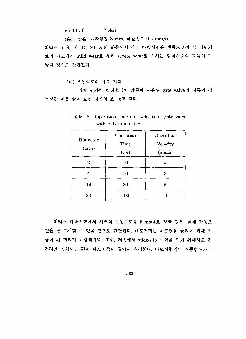
Stellite 6 : 7.5ksi
( £ £ . #•&, n > § t s ^ 8 mm,
5, 8, 10, 15, 20 ksi£] *>#6fl>
v\S.<>\)*] mild wear^. ^ severe wear^.
0.5 mm/fe)
7}
gate valve^
Table 18. Operation time and velocity of gate valvewith valve diameter.
Diameter
(inch)
2
4
14
20
Operation
Time
(sec)
10
30
30
100
Operation
Velocity
(mm/fe)
5
3
5
11
71 e l l -
stick-slip
7]-
- 8 0 -
mm 50 1 5 20 Hz
(2)
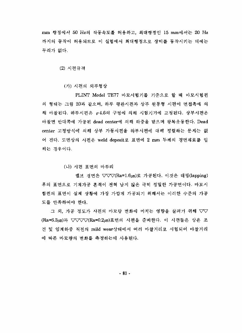
(7f)
PLINT Model TE77
204 £A*} ,
dead center^
center
weld deposits. S ^ ^ l 2 mm
- Dead
A)
(Ra=1.6/i1)S Hfl*£)Gapping)
W
mild
- 81 -

WEAR SPECIMEN
H I, 1 ( r K*t%p (ai^'a)
STATIONARY LOWER
i t s \
.op' |^^
RECIPROCATING UPPER
Fig. 20. Dimension of wear specimen
- 82 -

fe- weld deposits] 3 W powder^
0.5x1.5x20" ^E
fe BJ«- -§-*fl 7>*iS4l weld deposit «oVlS-£--§.
^ ^ -i-3-i- s e a t i ^ i i nls]
Weld deposit«0^A5. *fl4*Rr ^l^^r 316 SS^
0.5
7f
- 8 3 -

3.7])
U. 313*8£3.
profilometerofl
- Transfer particle^l rolling^
adhesive wear< l $\O]A)
- 84 -

E. S^^r -fr*flSl ¥ ^ 3 3 . *
u.<Hl^ Co-59
311-
-85-
1*1-31 f- M ^ ^^"Sl-1- ^tb Co reduction program^ <y^-o.s.
Co # - g - « ifl^lll- ^*V A:t7l#Sl
^ Xi^ Co t^cfl^ll 71 #
1. Co-free
Co-free
2 ^ (Armacor M, Tristelle 5183),
(Nucalloy 488)^]^, 7 l ^ ^ i | 4 i i 7 f l s i 4-8-=!^. <&^ Stellite 6
H , £$ ^ ^ ^ ] ^ 1 ^ ^ ) jgife- TIG316SS
2. Test bop
loop A ] ^
loop ^ ^ ^ ^ -§-# %•% %£,f>\q £ <&7-± i S . -^^^1^-8- test loop
Al^ ^J?^, ;g*H system^
zero^JI - g r i ^ x } ^ ^^-§-^(autoclave ifl -)«>l ± 0°C,
l-
- 86 -

3.
test loopl- °l-8-«M 300r, 1500 psi,
. zf
Nucalloy
Armacori^ TristelleSi °1
4.
. Armacor ^-#Sl ^-f,
. 7lE}
21-1- ^-o] ji5.7fl ^-
- Fe2B
Nucalloy
Stellite
5.
Co-free ttlLS
Co 9J Co-free ^
Co-free
Co-base Stellite ^^-A
6.
- 87 -

•a-
Co low Co/Co-free
Co

1. C. J. Wood, "Maintenance of Recent Techniques for LWR
Radiation-Field Control", EPRI-4505-SR, March 1986.
2. H. Ocken, "Cobalt Reduction Guidelines", EPRI NP-6737, Mar, 1990.
3. D. B. Heard & R. J. Freeman, "Cobalt Contamination Resulting from
Valve Maintenance", EPRI NP-3220, Aug. 1983.
4. U.S. Patent No. 4725512, 1988.
5. Non-Cobalt Alloys for Nuclear Application, Thermadyne-Catalog, 1993.
6. Young-Jin Kim, "IGSCC Mitigation Technology in LWRs," Seminar
Presented to KAERI, GE Corporate R&D Center, Nov. 21, 1995.
7. D. M. Himmelblau, J. Chem. Eng. Data 5, p.10, 1960.
8. £ ^ e 3 , "Metamorphic ^g-^g- <>l-g-*V - ^ . g ^ o } m.A^» 9 3)
2fl3.#£ ^5^1-g", 1995.
9. P. J. Hofmann and L. C. Friedrich, "Laboratory Evaluation of
Iron-Based Hardfacing Alloys," EPRI NP-5874, June 1988.
10. C. A. Bergmann et al., "Evaluation of Cobalt Sources in Westinghouse
Designed Three- or Four-Loop Plants", EPRI NP-2681, October 1982.
11. T. R. Young et al., "Cobalt Source Identification Program", EPRI,
NP-2685, October 1982.
12. C. A. Bergmann and E. I. Landermann, "Cobalt Release from PWR
Valve", EPRI NP-3445, July 1984.
13. L. Nolin, "Cobalt Replacement in Primary Valves", Virginia Power
report NP-1284, August 1, 1988.
14. H. Haynes, American Patent Paper No. 873 245
- 89 -

15. E. W. Ohriner and E. P. Whelan, "Development of Cobalt-free
Hardfacing Alloys for Nuclear Applications : 1984 Progress," EPRI
NP-4237, September 1985.
16. AMAX, "Production Weld Deposition, and Evaluation of Wear-Resistant
Iron- based Hardfacing Alloys," EPRI report, to bepublished.
17. W. J. Schumacher, "A Stainless Steel Alternative to Cobalt Wear
Alloys," Chemical Engineering, September 21, 1981.
18. E. I. Landerman et al., "Evalution of Low-Cobalt Alloys for Hardfacing
Applications in Nuclear Components," EPRI NP-3446, August 1984.
19. Velan Inc., "Laboratory Evaluation of Cobalt-free, Nickel-based
Hardfacing Alloys for Nuclear Application," EPRI NP-4993, March 1987.
20. P. A. March, "A Preliminary Assessment of the Cavitation Erosion
Resistance for EPRI/AMAX's NOREM Alloys," Norris, Tenn. : TVA
Engineering Laboratory, January 1989, TVA Report WR28-4-900-233.
21. H. Ocken, "Cobalt Reduction Guidelines, Rev. 1," EPRI-TR-103296, Dec,
1993.
22. ANNUAL BOOK OF ASTM STANDARDS, SECTION 3 : Metals Test
Methods and Analytical Procedures, VOLUME 03.02 Wear and Erosion;
Metal Corrosion, ASTM, 1993.
G-32 Standard Test Method for Cavitation Erosion Using
Vibratory Apparatus
G-77 Standard Test Method for Ranking Resistance of Materials
to Sliding Wear Using Block-on-Ring Wear Test
G-98 Standard Test Method for Galling Resistance of Materials
G-99 Standard Test Method for Wear Testing with a Pin-on-Disk
-90 -

Apparatus
G-115 Standard Guide for Measuring and Reporting Friction
Coefficient
- 91 -

KAERI/RR-1584/95
*fl- / -^1
<£ ^ 7.} J f A} lg
91 p.
^ d 1 ^ * *AM!* , 1 ^ » 4 ^ rt-
t^lJl(-?-^ i§7V7]^7ll^-) ) <ycj^)l(^-S]
oloj^(W-<S]Jg7l-7l^7B#), ^ ^ ^ - ( S l - ^
-n-( O ), :¥-( )
INIS^^l 3.^
3.7]
fl<H^l^)1996. 1
Cm
711 ( O ), tfl4«l( ), _ ^ « 1 ^
a^- (300^:^ i414)
7]^.$] iga. T^ig^Hsi
&l Co-free fl^ir ^ 3
(Nucalloy 488)-=r - S ^ K
S^^l TIG -S-^*!-^ °1
l^Hr 7f-&^ ;?]4 T -S}-*}"
^ 300°C, 1500 psi^ofl
^I-^-0] "T-T^ - ^ — 5 . M
^ t f l^ l^S.^ .A^ 7 > - ^
^ ^ . 4 'id^, Co-free H
nMl*?) ?!•?]— (10^°mi4)
i. ^F-g-sj^. &-fe Stellite ^^-^- cfl^lsf^l 4 ?
tHS- 2*(Armacor M, Tristelle 5183)4 4 -
2 ^ l ^ ^ Stellite 6 ^flSir i^-*f-^ # 4 ^ 4
oj Hj 77 A-]
i^i ^ - ^ i^
^-^-^- 316SS
^:?1# S.A}-§ ^ 5ife- - -<i)A] -§- test loop-i- ^ ^ ) , l)^«>
A) ijt^lT^-i- s%7}$; T jj). Stellite 6 4 Nucalloy 4884 -T-^
4ist4. •8- 'f' 7j£ # ^ 1 4 Nucalloy4 ;
# ^ 4 ^ - -T-E! Nucalloy 488 ^ ^ ^ - T - ^H
)61 ^ ^ - ^ ^ -°vl*l-^4. Co ^g- tfl^7l#4
3- ?ll*^*, «fl4si 7lifr*!#, -xfl ^ ^ ^ »j
« * W « . Co-free W , « ^ ^ , ^
^s] Stellite $•
«. ^v<a^l4
"est Loop

BIBLIOGRAPHIC INFORMATION SHEET
Performing Org.Report No,
Sponsoring Org.Report No.
Standing Report No.INIS Subject
CodeKAERI/RR-1584/95
Title / SubtitleReplacement of Co-base Alloy for Radiation ExposureReduction in the Primary System of PWR
Project Manager and Dept Jung Ho, Han Corrosion Evaluation
Researcher and Dept Kye Ho, Nho (Corrosion Evaluation) Duk Jae, Lim (CVCS)
Deok Hyun, Lee ( * ) Jin Kun, Ahn ( " )
Pub. place Taejon Pub. Org KAERI Pub. DATE 1996. 1
Page 91 p. III. and Tab Yes ( O ), No( ) Size Cm
Note
Classified Qpen( O ), Outside( ), _Class Report TypeResearch
ReportSponsoring Org. Contrct No.
Abstract (About 300word)
Of numerous Co-free alloys develped to replace Co-base Stellite used in valvehardfacing material, two iron-base alloys of Armacor M and Tristelle 5183 and onenickel-base alloy of Nucalloy 488 were selected as candidate Co-free alloys, andStellite 6 was also selected as a standard hardfacing material. These four alloys werewelded on 316SS substrate using TIG welding method. The first corrosion test loopof KAERI simulating the water chemistry and operation condition of the primarysystem of PWR was designed and fabricated. Corrosion behaviors of the above fourkinds of alloys were evaluated using this test loop under the condition of 300°C, 1500psi. Microstructures of weldment of these alloys were observed to identify bothmatrix and secondary phase in each weldment. Hardnesses of weld deposit layerincluding HAZ and substrate were measured using micro-Vickers hardness tester.The status on the technology of Co-base alloy replacement in valve components wasreviewed with respect to the classification of valves to be replaced, the developmentof Co-free alloys, the application of Co-free alloys and its experiences in foreignNPPs, and the Co reduction program in domestic NPPs and industries.
Subject Keyword (About 10 words) Co Replacement, Primary System, Co-free Alloy,
Valve Hardfacing Material, Corrosion, Test Loop
S 3 1*M3
1996^19% ^
i ft 13a1 « 18H
p m
•* • « • "*"
W
HIM
f.
150