replacement of the movable span of the galveston … · replacement of the movable span of the...
TRANSCRIPT

Replacement of the Movable Span of the Galveston Causeway Railroad Bridge
over the Intracoastal Waterway
Report Written by:
Mr. Jose Mares, P.E. Mr. Ralph Eppehimer, P.E. Mr. John R. StridBNSF Modjeski and Masters, Inc. Cianbro/Brasfield & Gorrie, JV
5800 North Main Street 1055 St. Charles Ave., Suite 400 3021 7th Ave. SouthSaginaw, TX 76179 New Orleans, LA 70130 Birmingham, AL 35233
Phone: (817) 352-2906 Phone: (504) 524-4344 Phone: (205) 714-1344
Submitted to:
AREMA 2013 Annual Conference
Abstract
This paper describes details and procedures used for the replacement of a rolling leaf bascule span with a new vertical lift span to increase the marine channel width. The primary challenge was maintaining the high volumes of rail and marine traffic with only minimal interruptions during construction. The existing concrete arch spans dating to the early 1900’s would remain as the approach spans to the new lift span. The new lift span tower piers were designed to replace the abutments for the arch spans as well as to support the new lift bridge. Building the new pier foundations included driving piles through holes cored in the arch spans, and provision of a temporary sheet pile/tie rod system to stabilize a narrow strip of railroad track across remaining portions of the arch spans. The new 383-foot long steel truss lift span was erected on land and then transferred to a barge for floating into position between the new towers. The span change-out operation included setting the new lift span in position adjacent to the bascule span with only inches between the two spans. This close alignment required removal of the rack and pinion of the bascule on one side to allow enough clearance to set the lift span. The sequence then required operation of the bascule on the single remaining rack and pinion, before the bascule span was floated out basically intact on the same barge used to float in the lift span. This paper provides perspectives of the Railroad, the design engineers, and the construction contractor.
Paper length = 7,377 words
© AREMA 2013®788

Table of Contents
1.0 INTRODUCTION
2.0 BACKGROUND2.1 Brief History – 1987 Scherzer Bascule Span
3.0 CONSTRUCTION MANAGEMENT SERVICES BY BNSF STRUCTURES3.1 Fabrication – Structural and Mechanical3.2 Structural Review
4.0 PLANNING FOR SPAN CHANGE-OUT4.1 BNSF’s Scope of Work
5.0 UNUSUAL ASPECTS OF THE MOVABLE SPAN REPLACEMENT5.1 New Tower Foundations Integral with Existing Arch Approach Spans 5.2 Temporary Track Stabilization over Remaining Arch Span Sections 5.3 Single Rack and Pinion Operation of Bascule Span
6.0 PROJECT CONSTRUCTABILITY CHALLENGES6.1 Active Rail and Marine Traffic6.2 Environmental and Geographic Conditions of Galveston, Texas6.3 Access to the Work and General Logistics of the Site
7.0 INNOVATIVE PROJECT MEANS AND METHODS7.1 H-Pile Installation7.2 Mass Erection and Concrete Placement7.3 Span Erection and Change Out
8.0 CONCLUSION
List of Figures
Figure 1: Galveston Causeway Railroad Bridge with the bascule span, parallel to the I-45 highway bridge
Figure 2: New vertical lift span of the Galveston Causeway Railroad BridgeFigure 3: Concrete arch spans of the mainland approach at the new lift span pier and
towerFigure 4: Temporary track stabilization over the arch spans through the work zoneFigure 5: Bascule span rack frame and pinion prior to removalFigure 6: Bascule span rack frame in process of being cut and removedFigure 7: Active railroad track through work siteFigure 8: Barge tow passing through the work area
© AREMA 2013® 789

Figure 9: Splicing and driving piles through the arch span along the railroad trackFigure 10: Pile driving operation for the new pier foundationsFigure 11: Pumping concrete from the I-45 highway bridge through slick line to
railroad bridgeFigure 12: Slick line running atop barges between the bridgesFigure 13: New lift span structural steel erection on landFigure 14: New lift span being floated into place at the bridge site
1.0 INTRODUCTION
The movable span of the Galveston Causeway Railroad Bridge, which was a rolling leaf bascule span built circa 1987, has been replaced with a new, longer vertical lift span. The long existing approaches to the movable span, consisting of concrete arch spans that were built circa 1911, remain in service. The bridge carries a single railroad track of the Burlington Northern Santa Fe Railway (BNSF) across Galveston Bay. The purpose of the span replacement project was to improve the waterway for navigation by increasing the width of the navigation channel passing through the bridge from 109 feet clear to 300 feet clear, to match the available horizontal navigation clearance of the adjacent I-45 highway bridge (Figure 1).
Figure 1: Galveston Causeway Railroad Bridge with the bascule span, parallel to the I-45highway bridge
The Galveston Causeway Railroad Bridge is owned by the County of Galveston, and operated by the BNSF Railway. The span replacement project was primarily federally funded by the United States Coast Guard Program for Alteration of Bridges under the Truman-Hobbs Act and the American Recovery and Reinvestment Act. Other parties also participated in the project funding, with the primary stakeholders being the U.S. Coast Guard, the County of Galveston,and the BNSF Railway. The project also included the relocation of two potable water pipelines which cross the bridge approaches and pass under the navigation channel. The waterlines serve the City of Galveston, with one line being owned by the City, and the other being owned by the Gulf Coast Water Authority.
The span replacement project required special procedures to ensure that the bridge would remain in service during the construction period with only minimal interruptions to rail and marine
© AREMA 2013®790

traffic. Only 82 hours of marine closures and 16 hours of rail closures were provided for the span change-out operation. The new structural steel vertical lift span, which is a through-truss span that is 383 feet in length, was erected on land and then, to accomplish the span change-out, was transferred to a barge and floated to the bridge where it was set between the new steel lift towers (Figure 2).
Figure 2: New vertical lift span of the Galveston Causeway Railroad Bridge
2.0 BACKGROUND
The railroad bridge is located on the Gulf Intracoastal Waterway at Mile 357.2, and crosses Galveston Bay to connect the mainland to the island of Galveston, Texas. Approximately 14trains per day cross the railroad bridge, providing rail service to the Port of Galveston. An average of 40 marine vessels per day, mostly barge tows, pass through the bridge.
After determining that the Galveston Causeway Railroad Bridge was an unreasonable obstruction to navigation, the U.S. Coast Guard issued the Order to Alter in June 2001, which mandated that the movable span be replaced with a new vertical lift span to provide a minimum of 300’ of horizontal clearance and a minimum of 73’ of vertical clearance above mean high water. The design of the span replacement project was authorized in May 2005. Modjeski and Masters, Inc. was engaged by the County of Galveston for engineering design services, with funding from the U.S. Coast Guard Bridge Program. The first bids for the construction project were received in September 2009, but the contract was not awarded then. Following a value engineering effort, the construction contract was re-advertised and bids received again in February 2010. The Joint Venture of Cianbro/Brasfield & Gorrie was the successful bidder and was awarded the construction contract. Construction started with the Notice to Proceed in June 2010 and was substantially complete by January 2013.
Representing the project stakeholders, oversight of the construction project and construction support services were performed by a team that included members of the U.S. Coast Guard, BNSF, the County of Galveston, and Modjeski and Masters, Inc.
© AREMA 2013® 791

2.1 Brief History – 1987 Scherzer Bascule Span
The 1987 Scherzer bascule span was designed and built by American Bridge Corporation under the oversight of the Atchison Topeka Santa Fe Railway (ATSF). Construction of the new 124’-5” bascule span began in July 1987 and was completed in April 1988. During the different construction phases the schedule incorporated two marine and railroad outages, first closure granted 24 hours with the second allowing for 48 hours in duration. The new bascule span replaced the 1912 Scherzer that was part of the original Galveston Causeway Bridge. It is important to note that this crossing can see in average 1,200 vessels per month as they traverse the Galveston Intracoastal Waterway, an operational characteristic that drove some specific considerations into the design criteria of the new 1987 span. One of these attributes was the ability for the new span to sustain its own dead load in the event one of the lower chord members was damaged or severed by marine collision. This attribute required increased resistance of the floorbeam and stringer system in order to transfer the maximum load from the chord to the end posts without exceeding the yield point of the steel. This characteristic coupled with the lowerchord built-up member design, allowed for individual panel repairs to be completed without major stability retrofits to the truss or significant additional member removal in the event of damage.
1987 Scherzer Bascule General CharacteristicsLength – 124’ 5”, Weight – 2,150,000 lbs. (movable steel portion only)Loading Live Load Cooper E80
Impact per the 1985-1986 ed. AREMA Manual Roadway AASHTO H20Wind 50 PSF bridge in any position
Operating Time: 4.5 min opening, 4.0 close (After electrical upgrades, time recorded from release of locks and brakes)Retrofits/Modifications: No structural or mechanical retrofits
3.0 CONSTRUCTION MANAGEMENT BY BNSF STRUCTURES
During the replacement of the Galveston Railroad Bridge project, BNSF had the responsibility to oversee the construction of the new vertical lift span as well as to incorporate the construction of the two new segments of main waterline into the overall project schedule. This paper concentrates on the bridge replacement. During the project, BNSF assembled a management team that worked closely with the U.S. Coast Guard, the County of Galveston and Modjeski and Masters in the management of this project.
As is expected with a project of this size and complexity, various activities required off-site supervision/inspection from third party companies to ensure quality and consistency in fabrication and materials. BNSF Structures involvement in managing these tasks along with planning and coordination within the different BNSF departments is covered in the following sections.
© AREMA 2013®792
3.1 Fabrication – Structural and Mechanical
The Joint Venture (Cianbro/Brasfield & Gorrie) subcontracted G&G Steel and Hirschfeld Industries for the fabrication of the mechanical and bridge structural components, respectively.BNSF Structures involvement was to manage in-shop third party inspections as conducted by BureauVeritas at G&G Steel in Russellville, AL and TUV Rheinland at Hirschfeld in the San Angelo, TX fabrication shop. This process entailed frequent review of Requests for Information, Non-Compliance Reports, and specific issues that developed as the fabrication progressed. During the review process, BNSF worked closely with the Engineer of Record group of experts to find cost effective solutions that would have the least impact to the project and still meet the stakeholders’ expectations.
3.2 Structural Review
BNSF Structures had a key leading role in the coordination with other railroad departments as the entity that fully understood the project not only from a technical and schedule/sequencing perspective, but also from the perspective of operational challenges the project would bring during its duration. As the user and maintainer of the structure, BNSF would closely manage the review of all modifications, change proposals, and specification deviations. One of the key attributes to this process and the overall success of the project was the ability of the team to maintain an open mind to different ideas and proposals to foster innovation by establishing conscientious check points that would guarantee safety and a successful end result. Examples of some of these proposals are mentioned later on in the paper.
4.0 PLANNING FOR SPAN CHANGE-OUT
In preparation for the “change out” date, BNSF gathered key personnel from the different departments (i.e. Engineering Services, Structures, Track, Signal, Transportation) to attend frequent planning meetings in order to discuss impact to train operations, signal testing and sequencing, track construction, and the key milestones during the outage that would indicate an adequate “on-time” progression of the timeline. Once a preliminary plan was put together that would satisfy a best fit scenario around the outage duration, coordination meetings were set with the Joint Venture team to incorporate their plan and make all pertinent modifications so that a “change out” sequence could be finalized.
4.1 BNSF’s Scope of Work
During the “change out” day, BNSF had several key responsibilities that had to be incorporated within the 72 hours outage; some of them listed as follows:
- BNSF Transportation team - Strategically stage and mobilize trains across the division in preparation for the outage.
- BNSF Structures - Monitor the old and new bridge during “float in” to ensure there was no damage or unforeseen conditions that could compromise the movement of trains.Trains were mobilized on the old structure during the outage after the completion of the new span float-in and prior to demolition activities on the old bascule span.
- BNSF Structures – General inspection of the span and rail alignment, fully seated and open conditions, evaluation of structure under initial traffic, adequacy of span movement throughout travel distance.
© AREMA 2013® 793
- BNSF Track - Remove and install approximately 1000 feet of new track leading to the new structure on both ends (North and South). This task was completed ahead of schedule.
- BNSF Signal and Telecom - Cut over and test systems on new bridge. The cut over was completed on schedule, and followed by several days of testing.
5.0 UNUSUAL ASPECTS OF THE MOVABLE SPAN REPLACEMENT
Three aspects of the replacement of the movable span of the Galveston Causeway Railroad Bridge are featured in the text under the following three subheadings. Movable span replacement projects of this type, which require minimal interruptions to traffic carried by the span and to marine vessels navigating through the channel, are always complex and challenging. While there often tend to be some basic techniques commonly employed to address a range of conditions encountered during the course of this type of work, with details modified as needed to suit the particular project, some projects have circumstances that require special solutions. The following text identifies and describes three particular aspects of the subject Galveston project that are not considered to be common methods used on this type of project. Each of these aspects required a significant engineering effort from both the design and construction divisions of the project team.
5.1 New Tower Foundations Integral with Existing Arch Approach Spans
The first unusual aspect for this type of project was the need to design and construct the new lift span and tower foundations to be structurally integral with the existing concrete arch approach spans. The long approaches crossing Galveston Bay, each consisting of a series of concrete arches, were to remain in service and would tie into the new lift span structure. The arch spans were built circa 1911, and are typically 78’-0” in length each, except those immediately adjacent to the bascule span are slightly longer. The approach arch spans were built wide enough to accommodate three railroad tracks, although the bridge currently only carries a single track. The old bascule span foundations on either side of the navigation channel served as abutments which resist the thrust forces transmitted longitudinally through the series of concrete arch spans in each approach. As the intent of the project was to provide a wider navigation channel, the old bascule span foundations were to be removed, along with two of the flanking arch spans on each side of the channel, when replaced by the new longer lift span and tower structure. Therefore, in the final modified configuration of the bridge, the substructure for the new lift span towers would have to serve as the new abutments for the existing arch spans, as well as support the new lift span, tower, and tower span loads (Figure 3). Additionally, the sequence of construction and techniques used for replacing the movable span would have to maintain stability of the arch spans, which remained in service to rail traffic, throughout the different stages of demolition and construction.
© AREMA 2013®794

Figure 3: Concrete arch spans of the mainland approach at the new lift span pier and tower
The solution is summarized as follows. The design required, as a first step, that the two arch pier stems of the arch spans, within which the new tower foundations were to be located, were to be tied together with a longitudinal bracing system at the approximate water level, Elevation 0.00’ MSL, to resist longitudinal thrust during periods after the concrete arch has been compromised, and before the new pier concrete has been sufficiently placed and cured. Heavy W36 structural steel beams were used for this bracing. Transverse structural steel members were also framed into the longitudinal members to provide additional bracing and to support the steel sheet pile cofferdam walls driven parallel to the bridge to enclose the areas of the new foundations between the existing arch pier stems. The area enclosed by each cofferdam was approximately 78’ x 100’, and each cofferdam was excavated to Elevation -19.00’. Then, to facilitate the driving of the required 240 steel H-piles for the new foundations, 24” diameter holes were augured from deck level through the arch fill within pipe sleeves, and then cored through the arch concrete, at each pile location. Base of rail is about Elevation 17.25’, and the HP14 x 117 piles were driven through the holes in the arches to -175.00 tip elevation. After pile driving, tremie seal placement, and dewatering of the cofferdams, the H-piles were cut off to Elevation -12.50’. New mass concrete foundations were then poured in multiple lifts and in dry conditions within the cofferdams, between and against each of the existing arch pier stems. Bond breaker material was placed between the new and existing concrete surfaces, but the steel beam bracing system installed between the arch pier stems was fully encased by the new pier concrete. The new concrete pier tops at bases of the towers are at Elevation 9.04.
5.2 Temporary Track Stabilization over Remaining Arch Span Sections
The second unusual aspect of the subject Galveston project highlighted herein was the method devised for maintaining the railroad track and traffic over the remaining arch span sections during the partial removal of those arch spans. In order to allow certain construction activities to proceed after placing the tower pier concrete beneath the arch spans, such as the tower structural steel erection, and the new operator house construction, and to perform some demolition to provide clearance for the new span float-in, it was necessary to remove interfering portions of the existing arch spans in those areas. As these arch spans were still carrying the rail traffic through the work zone, the Railroad was very concerned about the plan to maintain the track during these
© AREMA 2013® 795
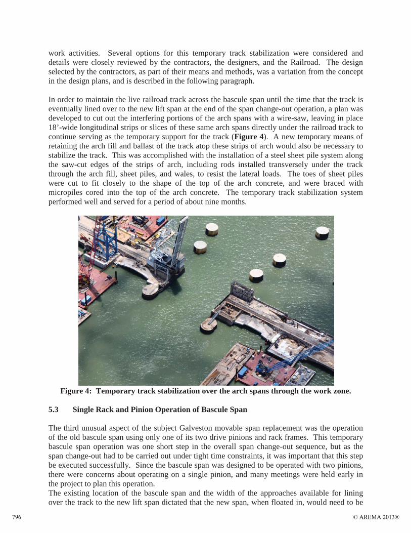
work activities. Several options for this temporary track stabilization were considered and details were closely reviewed by the contractors, the designers, and the Railroad. The design selected by the contractors, as part of their means and methods, was a variation from the concept in the design plans, and is described in the following paragraph.
In order to maintain the live railroad track across the bascule span until the time that the track is eventually lined over to the new lift span at the end of the span change-out operation, a plan was developed to cut out the interfering portions of the arch spans with a wire-saw, leaving in place 18’-wide longitudinal strips or slices of these same arch spans directly under the railroad track to continue serving as the temporary support for the track (Figure 4). A new temporary means of retaining the arch fill and ballast of the track atop these strips of arch would also be necessary to stabilize the track. This was accomplished with the installation of a steel sheet pile system along the saw-cut edges of the strips of arch, including rods installed transversely under the track through the arch fill, sheet piles, and wales, to resist the lateral loads. The toes of sheet piles were cut to fit closely to the shape of the top of the arch concrete, and were braced with micropiles cored into the top of the arch concrete. The temporary track stabilization system performed well and served for a period of about nine months.
Figure 4: Temporary track stabilization over the arch spans through the work zone.
5.3 Single Rack and Pinion Operation of Bascule Span
The third unusual aspect of the subject Galveston movable span replacement was the operation of the old bascule span using only one of its two drive pinions and rack frames. This temporary bascule span operation was one short step in the overall span change-out sequence, but as the span change-out had to be carried out under tight time constraints, it was important that this step be executed successfully. Since the bascule span was designed to be operated with two pinions, there were concerns about operating on a single pinion, and many meetings were held early in the project to plan this operation.The existing location of the bascule span and the width of the approaches available for lining over the track to the new lift span dictated that the new span, when floated in, would need to be
© AREMA 2013®796

set alongside the old span with only inches of clearance between the two spans. Also, before the lift span could be moved into that position, the bascule span’s operating rack and pinion gears on that side of the bascule span, had to be removed to allow the minimal clearance for the lift span (Figures 5 and 6).
Figure 5: Bascule span rack frame and pinion prior to removal
Figure 6: Bascule span rack frame in process of being cut and removed
© AREMA 2013® 797

This in effect crippled the original operating mechanism of the bascule span, which was designed to be operated with two racks and pinions, one on each side, in a symmetrical fashion. The change-out sequence required that the bascule span be operated one time in this crippled fashion. The bascule span needed to be raised before float-in of the lift span to provide vertical clearance for the barge carrying the lift span into position, and then it had to be lowered one more time after setting the lift span and removing the barge, so that the bascule span could carry rail traffic for two more days until the bascule span was removed entirely and all rail traffic was transferred onto the new lift span.
The concerns among the project team, including the Railroad, the contractors and the designers, were the need to lock the differential of the gear reducer in order to cut off one side and still be able to run on the other side; the need to fine-tune the balance of the bascule span to minimize loads and improve control of the bascule span with only a single pinion; and whether the span would actually “track” properly without significant binding or other problems when driven with only one pinion. A simple device was designed and installed to lock the differential by “fixing” the shaft on the side of the reducer where the pinion was removed. After having found that the span was significantly counterweight-heavy, weight was added to the toe of the bascule span to adjust the span balance. A satisfactory balance condition of the bascule span was confirmed by determining the torque of the drive machinery with strain gages. The single pinion operation would also be conducted at a slow operating speed.
During the span change-out, when the time came to actually run the bascule span on the single pinion, it only lasted a couple minutes, was very smooth and quiet, and anyone observing that was not involved in the planning may not have realized that there was anything unusual about the operation. But those that were involved appreciated the successful run for a few moments, before becoming focused on the next aspect of the span change-out sequence. Although unconventional, the single pinion operation proved to be very successful and was relatively simple compared to alternative ways of moving the bascule and performing the span change-out.
6.0 PROJECT CONSTRUCTABILITY CHALLENGES
Project logistics and physical location were two of the most critical factors to account for when planning this construction project. Logistics include many different factors such as material delivery handling and storage, personnel and equipment access, surrounding traffic and activity, and general work site characteristics. The physical location of the project will establishimportant factors such as geographical characteristics, environmental conditions, and availability of resources. The Galveston Lift Span Replacement project had a very challenging technical scope; however the challenges of the overall project were exponentially compounded due to the logistical and environmental impacts of active rail and marine traffic, environmental conditions of the region and general logistics associated with the physical work site.
© AREMA 2013®798

6.1 Active Rail and Marine Traffic
During the execution of the work, there was a project requirement to coordinate construction with fully active marine and railroad traffic operations (Figure 7). The new bridge was installed directly adjacent to the existing rolling single leaf bascule that was set to be replaced. Work needed to be executed on and around the active railroad track, and also on each side of the very busy Gulf Intracoastal Waterway Channel (ICWW). During the project, typical railroad traffic would range from eight to fourteen trains per day. A majority of the trains were operated by Burlington Northern Santa Fe; however there was a small percentage of Union Pacific trains that shared the line into Galveston. Due to the fact that marine traffic was heavier than rail traffic, the default position of the old bascule and the new lift span was the up or open position. During construction marine traffic ranged from 15-30 barges per day depending on weather and time of year.
Figure 7: Active railroad track through work site
In order to work safely around the active rail line and marine channel, it was absolutely critical for the construction team to remain in constant communication with the full time BNSF railroad flagmen, and bridge tenders. While there were several methods of track protection during the execution of the work, the most common form of protection was a Form B with the limits set approximately 1.5 miles from the actual moveable bridge on each side of the causeway.
There were constant challenges with planning work that was executed on or around the track and required equipment and personnel to be in close proximity to the AREMA clearance envelope. This was an important consideration for means and methods of the work because the construction efforts had to be flexible enough to halt operations and secure all resources for passing rail traffic. In addition, there were always considerations given to work activities that did or may potentially foul the active track. These activities were coordinated closely with the flagmen and bridge tenders; however the project team was able to engineer away many potential fouling risks to the track. These efforts included additional stabilization measures for temporary structures and materials, controlling active work zones by forcing equipment to work away from
© AREMA 2013® 799

the track except for specifically planned activities, and selecting/sizing equipment more strategically (i.e. shorter crane booms, zero swing radius excavators, vertical swing stage platforms and barge mounted man lifts).
While a majority of the day to day construction was more closely coordinated with the railroad traffic, it was extremely important to be cognizant of the active marine traffic (Figure 8). The project team made special efforts to post large high visibility signage around the construction zone for both commercial and recreational traffic. The construction activities required a large marine fleet that was constantly maneuvering on both sides of the channel, and therefore it was imperative to remain in constant contact with the bridge tenders, waterway users and boat captains. The construction team was granted several periodic marine outages that were coordinated with the local USCG Vessel Traffic Service, along with all of the major waterway users. During the demolition of the old bridge and the transition to the new lift span, the project team worked closely with mariners to ensure that all necessary aids to navigation remained functional and compliant. This often meant temporary fender structures, temporary navigation lighting, notices to mariners, posted advertisements at local marinas and bait shops, signage at roads around the area, and even height indicator markings to help recreational boaters confirm that the new lift span was in the upright and locked position.
Figure 8: Barge tow passing through the work area
6.2 Environmental and Geographic Conditions of Galveston, Texas
In addition to the active rail and marine traffic, the physical location of the project proved to be just as challenging. Galveston, Texas can be a difficult location for marine construction due to environmental and geographic conditions. During the project, it was absolutely critical to plan the work activities around the constantly changing weather. It was necessary for the project team to be flexible and have alternative work options, when possible, because the water and weather conditions often would prohibit different types of work. While tidal fluctuations were minimal (+/- 1-2’) at the Galveston Causeway, there were strong currents ranging between 2-5 knots that
© AREMA 2013®800

made maneuvering marine equipment very challenging. Due to the relatively shallow depth of Galveston Bay, combined with minimal protection from land masses or structures, the strong winds that came through the area created very rough water, often suspending or significantly hampering work activities because of unsafe conditions, or preventing the execution of specific types of work. In fact during the winter months from November through February, it was not uncommon to lose 1-2 work days a week due to inclement weather brought on by the cold fronts and strong northerly winds.
The climate in Galveston can be very hot and humid during the expanded summer months from May through September. It is very important to ensure that all of the construction employees are exercising caution about warm weather conditions. Means for constant hydration, skinprotection, and cool areas for routine breaks all must be incorporated into the temporary construction facilities. The extreme heat can significantly affect productivity and actually reduces the amount of time employees can work during the summer months, because safety risks increase exponentially. This factor required the project team to utilize multiple work shifts, night work, and rotating schedules for craft personnel. As a result of being located right on the Gulf of Mexico, the water around Galveston has a high salinity level, and the salt air is highly corrosive. The caustic marine environment creates significant challenges not only for the installation of new work, but with maintaining sound working construction tools, equipment and supplies (i.e. rigging and false work).
6.3 Access to the Work and General Logistics of the Site
The third major logistical challenge associated with the Galveston Lift Span Replacement was the physical location of the project site. The actual jobsite was located in the middle of the causeway railroad bridge that is approximately 2.5 miles in length. While there was limited vehicle access out on the causeway, this had to be controlled due to the fact that the roadway was not for public transportation, and any traffic or parking could not impact the operations of railroad personnel (flagman, bridge tenders, signal maintainers, road masters, etc.). The construction team utilized minimal supervisor parking on the bridge, and the rest of the craft were transported with busses from remote parking locations at the end of the causeway, or via the water on work boats or barges. Inclement marine weather often hampered employee access via boat, therefore carpooling out onto the causeway was the most reliable mode of access to the work site. However, this was often a challenging process because the roadways were very narrow and required low speed travel due to the rough conditions of the red brick road that still remains from the original causeway construction in the early 1900’s. Even more challenging than employee access to the work site, was the delivery of material, equipment and supplies. Other than small items that could easily be transported on a flatbed truck, all materials and supplies has to be loaded onto a material barge at the main project yard that was approximately 1.5 miles from the jobsite, and transported via water to the work locations. This in turn required a crane or large piece of equipment to hoist and place all materials and supplies. This was a very time consuming exercise and it made pre-planning the work with all of the required resources very important to maintain production. The positioning of equipment such as cranes, boats and barges was additionally hampered by the I-45 highway bridge only hundreds of feet from the jobsite, and high tension electrical lines that ran the entire length of the railroad causeway bridge.
© AREMA 2013® 801

7.0 INNOVATIVE PROJECT MEANS AND METHODS
Active rail and marine traffic, environmental conditions and project logistics created additional challenges for the construction team throughout the project, however many of these were overcome and mitigated with innovative planning, creative construction means and methods and collaboration with the project owner and design teams. Three specific features of work that exemplified innovative construction means and methods to overcome project constraints were the installation of the driven steel H-Piles, the placement of mass concrete for the bridge piers, and the erection and float in of the new lift span bridge.
7.1 H-Pile Installation
The new pier foundations for the lift span towers are supported by driven steel HP 14x117 H-piles. There are approximately 120 piles under each foundation. The piles were originally designed to be driven to a tip elevation of -200 feet, however after a comprehensive dynamic load testing program, the engineer of record was able to confirm that the piles reached the required capacity at a tip elevation of -175, effectively reducing the total amount of driven pile by nearly 5000 linear feet and saving the project owner approximately $420,000. Despite the reduction in total pile length, the project team was still faced with several logistical challenges associated with the H-Pile installation.
Figure 9: Splicing and driving piles through the arch span along the railroad track
© AREMA 2013®802

Each individual pile was comprised of several shorter pieces spliced together to achieve the desired length (Figure 9). In order to minimize the amount of splices and increase efficiency, the project team elected to drive the first piece of each pile with either a 100’ or 105’ long HP 14x117 member. This is a very challenging process; specifically the rigging and handling of the large steel members. The pile sections were picked and set into place with either a 4100 ringer or a 4100 S2 crane (Figure 10). Due to the access constraints on the west side of the causeway bridge created by the high tension electrical lines, the ringer crane was unable to access the work area from that side of the bridge. This required the project team to source a much more light weight hydraulic pile hammer that could be hoisted with a traditional 4100 S2 crane, in lieu of the much heavier diesel impact hammer and leads used with the 4100 ringer crane. By using a more compact and lightweight pile driving set up, the team was able to more than double productivity because one crane could set the piles into the prefabricated templates or cored holes in the existing arch spans and the other crane could begin driving them based on which side of the bridge (east or west) the piles were located.
Figure 10: Pile driving operation for the new pier foundations
Another constraint associated with the installation of the H-Piles was the fact that all activities needed to be closely coordinated with the active railroad track. Each of the crane operators and foreman were in constant communication with the BNSF flagman. This allowed the crews to plan each of the hoisting, setting and splicing work around the movement of the trains. If a train was approaching the bridge, loose piles needed to be set back down on the material staging barge until the train had passed and the flagman cleared the work to resume. If a pile was in the process of being driven, the construction crew and the flagman would evaluate the amount of
© AREMA 2013® 803

time to complete the driving and make a decision whether the pile driving should finish or be suspended and the crane/hammer swung away parallel to the bridge where it would not foul the track. Perhaps the largest challenge was the splicing work, and managing when the crane could release from the pile section that was being spliced with the previous driven piece. The construction team was able to generate engineering data that supported a specific amount of weld on each splice before the crane could release the piece, and both the railroad and the designerswere comfortable with this information. It was still challenging to coordinate the splicing and welding activities so as not to impede rail traffic.
Due to the fact that both pile driving rigs were barge mounted cranes, all pile setting and driving activities were very much dependent on the weather. If the winds exceeded 30 MPH the cranes were not able to hoist and swing safely, and if the water conditions created listing of the barges greater than 3%, the cranes went out of the safe working ranges. This made it very important to plan the work so that during inclement weather, activities such as welding, staging of material and splicing preparation could be done to maintain a productive workflow.
7.2 Mass Concrete Placement
One of the greatest challenges that faced the construction team was the placement of all the mass concrete for the tower foundations. Each pier has approximately 5000 cubic yards of concrete that was placed in varying lifts ranging from 700 to 1300 cubic yards.
There were several constraints on the placement of the mass concrete, that included the maximum time allowed from batching to placement, the concrete slump and placement temperature requirements, the prohibition of driving concrete trucks onto the causeway bridge due to excessive loading of the roadway structure, and the concern about keeping a steady placement rate to prevent cold joints or early set up of the concrete.
During the planning stages of construction there were several ideas contemplated for the transportation and delivery of the concrete to the actual foundation locations.
The first idea was installing large concrete conveying systems on each side of the bridge and conveying the concrete approximately 2000 LF on the island side and 4500 LF on the mainland side. The problem with conveyors was that they were incredibly expensive, did not solve the problem of still requiring a placement boom or pump truck on a barge or at the end of the belt to control the placement location, and they needed the concrete to be at a much tighter slump for transport, putting it at risk of setting up too fast. The second idea was to use several (8-12) concrete buggies that can carry approximately 3 cubic yards and continuously shuttle the concrete up and down the bridge from either the island or the mainland. This concept would be very slow, created tremendous wear and tear on the old causeway, presented a traffic risk, and did not have a good solution for how the actual concrete would be placed into the foundation forms without the use of a placing boom or pump truck. The third idea was to load concrete trucks or large agitators onto barges and push them from either the bulkhead at the construction yard or the island and mainland causeway areas to the work locations, and unload them into a pump truck mounted onto a material barge. This process would involve a significant marine fleet, and made the entire process very susceptible to weather induced delays due to the fact the operations were solely waterborne. Ultimately there was also a risk of not getting the concrete to the foundation in time and having cold joints or premature curing and poor consolidation.
© AREMA 2013®804

The fourth and final idea, which was ultimately used, involved approximately 700 LF of high pressure 5” slick line on material barges with a high capacity trailer pump used forhigh rise concrete placement at one end and a 58 meter pump truck with a placing boom on the other end closest to the foundations. A third 42 meter concrete pump truck was located on the top of the I-45 causeway bridge, where it pumped concrete delivered by ready mix trucks into the high capacity trailer pump below, where it was propelled though the system and placed with the 58M boom (Figure 11).This method allowed the ready mix trucks to use conventional highway access to deliver
the concrete, while not compromising placement temperature or mix composition. This method was also not solely dependent on the weather, and the flexibility of the 58M boom truck allowed for adjusting to active rail traffic during concrete placement. The team was able to place the mass concrete at an average rate of 75 CY/hr., which proved to be considerably more productive than all other the options, while still maintaining the quality control requirements for the placement (Figure 12).
Figure 11: Pumping concrete from the I-45 highway bridge through slick line to railroad bridge
© AREMA 2013® 805

Figure 12: Slick line running atop barges between the bridges
7.3 Span Erection and Change Out
The original plan for erection of the lift span truss section was to utilize a series of large floating barges with jacking towers and multiple cranes and man lifts on adjacent barges or on the bulkhead where the erection barges were moored. Once the span was constructed, the large erection barge would be pushed out to the work area, where the lift span truss, weighing over three million pounds and spanning over 382’ in length, would be set on a temporary trestle supported by battered pipe pile bents and rolled into final position. This plan was contemplated throughout the estimating phase and even illustrated in the suggested construction sequence in the contract drawings. However, once the construction team evaluated the feasibility of this scheme and factored in the environmental and logistical constraints, it was fast realized that an alternate plan needed to be developed.
The construction team was very concerned with the adverse effects that the inclement weather would have on the span erection barge while the truss was being assembled. This posed a great risk to alignment and fit up of the floor system and top chords, which were fabricated with very tight tolerances to maintain the camber of the truss. There was also a great concern about personnel access with a water based operation. The construction team brought in a specialty heavy haul subcontractor and elected to build the truss on land and then load the erected structure onto a large ocean barge with the use of high capacity multi axle hydraulic trailers (Figure 13). Once the lift span was loaded onto the barge, it was then transported to the work site and floated into place with the use of a complex mooringsystem to overcome current, wind and wave action (Figure 14).
© AREMA 2013®806

Figure 13: New lift span structural steel erection on land
Figure 14: New lift span being floated into place at the bridge site
There was a considerable cost associated with erecting the lift span on land and transporting the structure after it was assembled, however the upfront costs were offset by production gains, advantages of a much safer work area, and the ability to maintain a high level of precision with the members of the truss. In addition the project team needed to upsize the end floor beams and increase the thickness of the steel gussets at the support locations at the bottom chords in order to
© AREMA 2013® 807

account for the trailer transports, however the additional money spent on steel modifications was well worth the risks that were mitigated with the revised float in scheme.
8.0 CONCLUSION
In conclusion, the Galveston Lift Span Replacement project was a very technically challenging project, where site logistics, environmental factors and active rail and marine traffic compounded the difficulty of completing the scope. The construction contractors, designers and owners wereable to successfully work together and develop several innovative construction means and methods to help mitigate many of the inherent risks and challenges to complete the work safely and successfully.
© AREMA 2013®808
Sept
embe
r 29
–O
ctob
er 2
, 20
13In
dian
apol
is,
IN
Repl
acem
ent
of t
he M
ovab
le S
pan
of t
he
Gal
vest
on C
ause
way
Rai
lroad
Brid
ge
over
the
Intr
acoa
stal
Wat
erw
ay
Jose
Mar
es, P
.E.,
Burli
ngto
n No
rthe
rn S
anta
Fe
Railw
ayRa
lph
Eppe
him
er, P
.E.,
Mod
jesk
i and
Mas
ters
, Inc
.Jo
hnSt
rid,C
ianb
ro/B
rasf
ield
&Go
rrie
, Joi
nt V
entu
re
Pres
ente
rs:
© AREMA 2013® 809

September 29 – October 2, 2013Indianapolis, IN
Introduction
Galveston Causeway Railroad Bridge with thebascule span, parallel to the I-45 highway bridge
September 29 – October 2, 2013Indianapolis, IN
New vertical lift span of the Galveston Causeway Railroad Bridge
Introduction
September 29 – October 2, 2013Indianapolis, IN
Background
Project LocationSeptember 29 – October 2, 2013
Indianapolis, IN
Background - History1893 - The Wagon Bridge:
The first vehicular crossing of Galveston Bay was the wagon bridge, completed in 1893.
The bridge consisted of 80-foot-long steel truss spans on concrete piers.
The bridge was destroyed in the 1900 hurricane and was not replaced.
(Photos: Rosenberg Library, Galveston)
September 29 – October 2, 2013Indianapolis, IN
Background - History
Construction of the first concrete bridge, circa 1911:
After the devastating 1900 storm, the need for a bridge capable of surviving hurricanes was clear.
Work on a new concrete structure began in 1909 and was completed in 1912.(Photos: Rosenberg Library, Galveston)
September 29 – October 2, 2013Indianapolis, IN
Background - History1915 Hurricane
Repairing the damage from the 1915 hurricane. The bridge structure itself survived the hurricane with virtually no damage, but the earth filled sections leading to the bridge were washed away.
Temporary wooden rail trestles from the shorelines to the bridge were immediately constructed to restore rail service.
Permanent repairs extended the concrete bridge structure to replace the earth filled sections.
(Photos: Rosenberg Library, Galveston)
© AREMA 2013®810

September 29 – October 2, 2013Indianapolis, IN
Background - History
1986 – Bascule Span Replacement
Galveston County Lift Bridge over the Intracoastal Canal, Galveston Bay
Contractor: American Bridge Site Work Began: July 1987Completed: April 1988
September 29 – October 2, 2013Indianapolis, IN
BackgroundReplacement of bascule span with new vertical lift span.
September 29 – October 2, 2013Indianapolis, IN
Background
Project Milestones
Order to Alter (OTA) Issued by the US Coast Guard 06/2001
Consulting Engineer (M&M ) Authorized to Design 05/2005
Coast Guard Approved PS&E 07/2009
Contract Awarded to Cianbro/Brasfield & Gorrie (JV) 05/2010
Construction Commenced (NTP) 06/2010
Substantial Completion 01/2013
Replacement of Bascule with New Vertical Lift Span
September 29 – October 2, 2013Indianapolis, IN
Construction Management by BNSF Structures
Structural Steel Fabrication
September 29 – October 2, 2013Indianapolis, IN
Construction Management by BNSF Structures
Machinery FabricationSeptember 29 – October 2, 2013
Indianapolis, IN
Construction Management by BNSF Structures
Control House
© AREMA 2013® 811
September 29 – October 2, 2013Indianapolis, IN
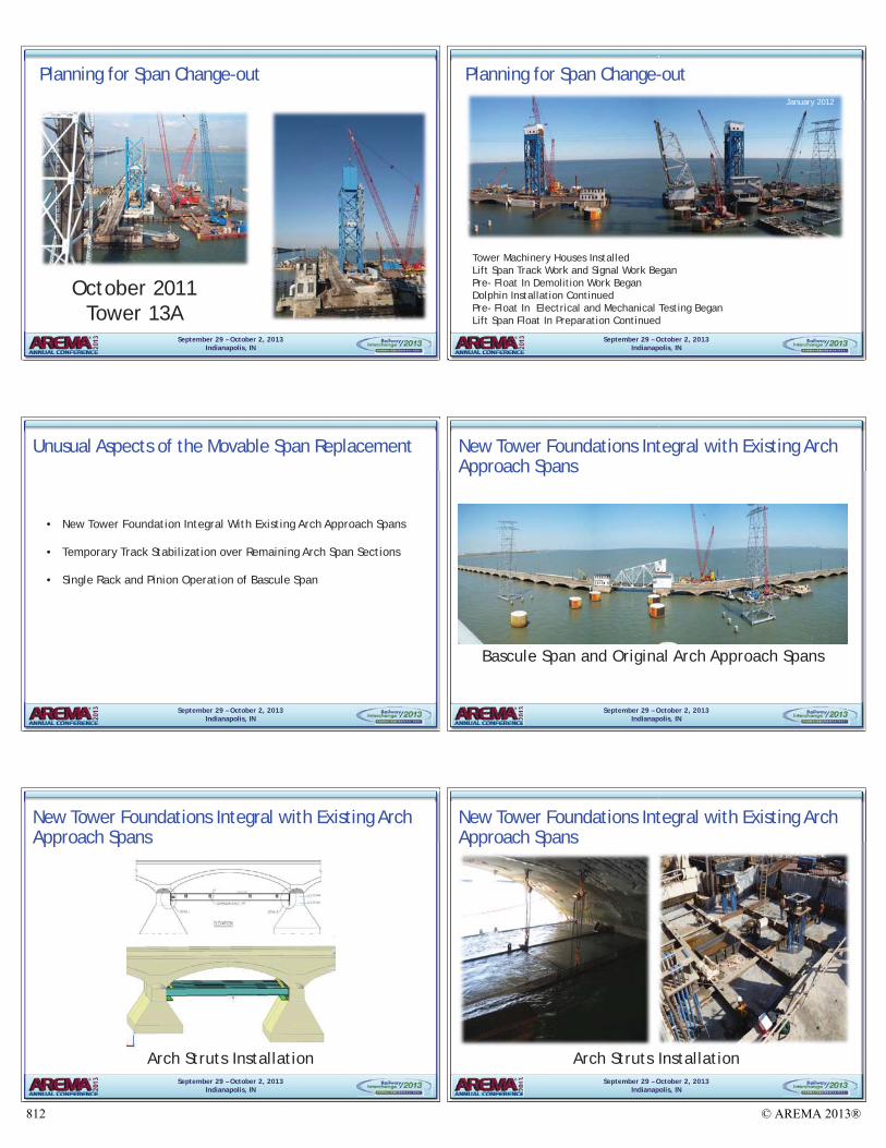
October 2011Tower 13A
Planning for Span Change-out
September 29 – October 2, 2013Indianapolis, IN
January 2012
Tower Machinery Houses InstalledLift Span Track Work and Signal Work BeganPre- Float In Demolition Work BeganDolphin Installation ContinuedPre- Float In Electrical and Mechanical Testing BeganLift Span Float In Preparation Continued
Planning for Span Change-out
September 29 – October 2, 2013Indianapolis, IN
Unusual Aspects of the Movable Span Replacement
• New Tower Foundation Integral With Existing Arch Approach Spans
• Temporary Track Stabilization over Remaining Arch Span Sections
• Single Rack and Pinion Operation of Bascule Span
September 29 – October 2, 2013Indianapolis, IN
New Tower Foundations Integral with Existing Arch Approach Spans
Bascule Span and Original Arch Approach Spans
September 29 – October 2, 2013Indianapolis, IN
New Tower Foundations Integral with Existing Arch Approach Spans
Arch Struts InstallationSeptember 29 – October 2, 2013
Indianapolis, IN
New Tower Foundations Integral with Existing Arch Approach Spans
Arch Struts Installation
© AREMA 2013®812

September 29 – October 2, 2013Indianapolis, IN
New Tower Foundations Integral with Existing Arch Approach Spans
Coring/Driving Piles through Arch SpanSeptember 29 – October 2, 2013
Indianapolis, IN
New Tower Foundations Integral with Existing Arch Approach Spans
Driving Piles through Arch Span
September 29 – October 2, 2013Indianapolis, IN
Temporary Track Stabilization
September 29 – October 2, 2013Indianapolis, IN
Temporary Track Stabilization
September 29 – October 2, 2013Indianapolis, IN
Temporary Track Stabilization
September 29 – October 2, 2013Indianapolis, IN
Single Rack & Pinion Operation of Bascule Span
© AREMA 2013® 813

September 29 – October 2, 2013Indianapolis, IN
Single Rack & Pinion Operation of Bascule Span
September 29 – October 2, 2013Indianapolis, IN
Single Rack & Pinion Operation of Bascule Span
September 29 – October 2, 2013Indianapolis, IN
Project Constructability Challenges
Active Rail TrafficSeptember 29 – October 2, 2013
Indianapolis, IN
Project Constructability Challenges
Active Marine Traffic
September 29 – October 2, 2013Indianapolis, IN
Innovative Project Means and Methods
H-Pile InstallationSeptember 29 – October 2, 2013
Indianapolis, IN
Innovative Project Means and Methods
Pile Driving Operation
© AREMA 2013®814

September 29 – October 2, 2013Indianapolis, IN
Innovative Project Means and Methods
Mass Concrete PlacementSeptember 29 – October 2, 2013
Indianapolis, IN
Innovative Project Means and Methods
Slick Line Running Atop Barges Between the Bridges
September 29 – October 2, 2013Indianapolis, IN
Innovative Project Means and Methods
New Lift Span Structural Steel Erection on LandSeptember 29 – October 2, 2013
Indianapolis, IN
Innovative Project Means and Methods
Transporting Lift Span to Barge
September 29 – October 2, 2013Indianapolis, IN
Innovative Project Means and Methods
New Lift Span Float-inSeptember 29 – October 2, 2013
Indianapolis, IN
Innovative Project Means and Methods
Bascule Span Float-out
© AREMA 2013® 815

September 29 – October 2, 2013Indianapolis, IN
Conclusion
Project CompleteSeptember 29 – October 2, 2013
Indianapolis, IN
Questions?
© AREMA 2013®816