replica-based crack inspection - nasa · draft 5/18/2009 1 replica-based crack inspection john a....
TRANSCRIPT

DRAFT 5/18/2009
1
Replica-Based Crack Inspection
John A. Newman1, Scott A. Willard2, Steve W. Smith1, Robert S. Piascik1 Abstract: Surface replication has been proposed as a method for crack detection in space shuttle main engine flowliner slots. The results of a feasibility study show that examination of surface replicas with a scanning electron microscope can result in the detection of cracks as small as 0.005 inch, and surface flaws as small as 0.001 inch, for the flowliner material. Keywords: Surface replica, Crack inspection, Small crack, Inconel 718 Introduction
Cracks have been found at slots in space-shuttle orbiter main engine liquid hydrogen (LH2) feed line gimbal-joint flowliners [1, 2]. These flowliners are located in the aft end of the orbiters (See Figure 1a) within the LH2 feedlines (See Figure 1b). Flowliners are constructed of Inconel 718 sheet material (0.05 inches thick) and are designed to provide a smooth flow of fuel over the bellows of the gimbal joint. The upstream and downstream flowliners, shown in Figure 1c, each contain 38 slots. The upstream flowliner slots are nominally 1.00 inch (25.4 mm) long and 0.25 inches (6.35 mm) wide, and the downstream slots are nominally 0.75 inches (19.1 mm) long and 0.25 inches (6.35 mm) wide (See Figure 1d).
Cracks were initially discovered by visual examination, and subsequent examinations using well-established non-destructive evaluation (NDE) methods (Eddy current and ultrasonic inspection with a crack detection resolution of approximately 0.075 inches (1.9 mm)) were also performed. All cracks found were 0.100 inches (2.54 mm) or longer and were weld repaired. The possibility of multi-site damage – the existence of multiple cracks at lengths just below the detection threshold – is a concern. The specific threat that cracked flowliners present is the release of foreign-object debris (FOD). Even a small piece of FOD (>0.015 inches (400 μm)) could damage downstream components including fuel pumps.
To ensure flowliners are free of small cracks, an alternate inspection method is needed that can reliably detect cracks much smaller than 0.075 inch (1.9 mm), which was the accepted NDE resolution at the initiation of this effort. Due to the location of the flowliners within the LH2 feedlines, the difficulty in accessing these components and the fact that cracks are known to initiate on the slot surface (i.e., damage is not sub-surface), surface replication (SR) appears to be a favorable inspection method. Additionally, sub-critical damage can be monitored by comparison with replicas taken at different times. Rather than directly examine a component, SR methods rely on inspections of surface replicas to characterize the damage state. The primary advantages of SR methods are that the component is not directly analyzed and that replicas document and preserve the surface conditions corresponding to specific times during the service life. The disadvantages are that only surface damage is documented and special care must be taken to ensure that the replica is an accurate representation of the actual surface conditions. Occasionally, flaws in replicas may occur such that the features on the replica do not accurately
1 NASA Langley Research Center, MS 188E, Hampton, VA 23681 2 Lockheed Martin Space Operations, Langley Research Center, MS 188E, Hampton, VA 23681.
https://ntrs.nasa.gov/search.jsp?R=20090020375 2019-03-28T16:33:25+00:00Z

DRAFT 5/18/2009
2
mimic the actual slot surface. For this reason, multiple replicas should be made for each slot surface, so that features found on one replica can be verified on another.
The objectives of this investigation are to determine the feasibility of the proposed surface replication method to find small cracks and characterize the surface finish of the polished slots. A recently developed SR method is proposed for this application due to its ease of use. This inspection method is validated through a test program where cracks were located in coupons designed to mimic the flowliner slot geometry. For the methods described within this report, it has been determined that this SR technique can accurately and reliably detect cracks as small as 0.005 inch.
Surface Replication Methods
SR methods have been used for decades as a way to monitor the initiation and growth of small cracks [3-5]. Two SR methods were used in this study; acetate tape replication and a silicon rubber-based compound commercially known as RepliSet3. The acetate tape method is well established and has been used for decades, but silicon rubber-based products represent a relatively new SR method. The RepliSet product is specifically marketed as a metallurgical product to produce replicas of materials. In general, the silicon rubber-based compounds are much easier to use compared with acetate tape. Because this application will require hundreds of replicas to be taken per vehicle, the relative ease of application and no need to dispense a solvent within a flight system makes the RepliSet product attractive for further evaluation, while the acetate tape method provides a basis of comparison for the silicon rubber-based methods.
For the acetate tape method, surface replicas are made using small strips or pieces of transparent acetate tape. The area of interest is covered by the acetate tape, with a small amount of acetone applied between the component and tape. Acetone partially dissolves and softens the acetate tape allowing it to flow against the specimen and into surface features. After the acetone dries, the acetate tape is removed as a replica of the surface.
The silicon-based compound is a two part product that is dispensed with a hand-operated dispenser and mixed through a static mixing nozzle. The nozzle and dispenser allow for easy application of the material to the flowliner slots. To insure that the silicon material is contained within the slots as it cures, a piece of tape is applied to the outside and inside surfaces. For this study, the RepliSet compound T3 was used which had a working time of approximately 3 minutes and a curing time of 10 minutes.
Experimental Procedure
The simulation of cracks at flowliner slots was accomplished by fatigue testing specimens containing slots with the same dimensions as an upstream flowliner. Two types of specimens, shown schematically in Figure 2, were provided by NASA Marshall Space Flight Center. Both specimen types were machined from the same 0.05-inch-thick Inconel 718 sheet product used for the flight hardware. The slots in all specimens were punched and polished using procedures similar to those of flight hardware. Double-edge notch specimens (kt = 3.55) were fatigue tested at R = 0.1 and a maximum load of Pmax = 4.5 kips, which corresponds to a notch stress of 160
3 RepliSet is a trademark of Struers.

DRAFT 5/18/2009
3
ksi.4 To achieve the same notch stresses (160 ksi), center-slot specimens (kt = 3.52) were fatigue loaded at Pmax = 3.35 kips (R = 0.1). Fatigue tests were performed in room temperature laboratory air at loading frequencies ranging from 5 Hz to 10 Hz. Periodically, testing was interrupted to produce slot surface replicas using both replication methods. Replicas were produced with the specimen under zero applied load and at the maximum applied load. It is presumed that any crack would be more readily detected using a replica taken at the maximum load because any crack present would be fully open. Since the flight hardware is not subject to remote loading during inspection, the zero load state is consistent with the state of the components to be inspected. Comparing the results (crack lengths) determined from zero-load and maximum-load replicas will help determine if crack length determinations are dependent upon the loading condition.
Specimens were fatigue loaded, and periodically replicated, until small cracks were observed. Multiple specimens were cracked to develop a specimen set with a good distribution of cracks ranging in size from 0.005 inch to 0.025 inch (0.127 mm to 0.635 mm). For each specimen, crack length determinations were made using (1) acetate tape replicas, (2) silicon-rubber based replicas, and (3) sectioning of the specimen to facilitate direct examination of the cracked region using a scanning electron microscope (SEM). The results over a wide range in crack lengths and loading conditions will be used to determine the resolution and usefulness of the process used for the silicone-based compound inspection.
All flowliner slots have been polished following the discovery of cracks in 2002 [2]. It is important to understand how the polishing process may affect the identification of cracks that were either not fully removed by polishing or were not previously identified. Polishing may smear material over the crack surface, making it more difficult to identify a crack using a replication method. For this purpose, cracked specimens were polished without fully removing the crack and inspected using the replication methods as well as directly examining the surface of the cracked specimen.
Experimental Results
Reproducibility Inspection of flight hardware within the feedlines requires that no foreign matter is left in the
system following inspection. This means that any replication material that may be entrapped within a crack could be dislodged during operation and adversely affect the fuel systems downstream. Additionally, the entrapment of replication material can lead to inaccurate inspections. To determine if such an issue may affect the silicon rubber-based material, several cracks were subjected to repeated replication followed by direct visual inspection of the cracked region. Figure 3 contains SEM images of replicas of a crack, using an acetate tape (a) and the RepliSet material (b and c). Figure 3b is an image for the first RepliSet replica produced for this crack, while Figure 3c is an image of the fifth RepliSet replica produced for this crack. The crack details on each of these three replicas are similar. Additionally, direct examination of the cracked regions using the SEM did not reveal any accumulation of foreign material.
Crack detection All crack length determinations from the test specimens are summarized in Table 1. Here, the
4 The stress concentration factors presented here are based on the gross-section stress – the average gage-section stress that would exist if the notches were not present.

DRAFT 5/18/2009
4
length of each crack detected, using both replica methods and direct SEM examination of each specimen, are listed (some specimens contain multiple cracks). If the RepliSet method lacked the resolution to replicate crack features, then crack length values would likely consistently less than for the other two methods. No such trend is seen in these data although there does appear to be some variability. A qualitative comparison of the RepliSet method can be made by comparing SEM micrographs of the same features. Comparisons are made for several specimens in the following sections.
Specimen #1 Specimen #1 was the first specimen tested and was originally fatigue loaded at a notch stress
of 140 ksi (R = 0.1). After 147,000 cycles, no cracks were detected and loads were increased to a notch stress of 160 ksi. All other specimens were strictly loaded at a notch stress of 160 ksi and R = 0.1. Three cracks were detected on replicas made at a cumulative cycle count of 270,000 (123,000 cycles at 160 ksi notch stress). The largest crack was a corner crack with an approximate surface length of 0.014 inch (350 μm). Two smaller surface cracks of lengths 0.004 inch (110 μm) and 0.001 inch (27 μm) were also detected. The large crack can be seen in an SEM image of an acetate tape replica, (Figure 4a) and the two smaller cracks can be seen at higher magnification (Figure 4b).
The slot surface was replicated using both replica methods. Additionally, cracks were detected by directly examining the slot surfaces in an SEM. To characterize the crack detection capability of RepliSet, SEM images of RepliSet were compared with similar images of acetate replicas and a direct examination of the slot surface. Cracks are more likely to be detected on replicas taken under an applied tensile load because the cracks are open. In this comparative study, acetate tape replicas were taken at maximum load (160 ksi notch stress). RepliSet replicas were taken on unloaded specimens because this stress state is believed to better represent the stress state of the flowliners during inspections.
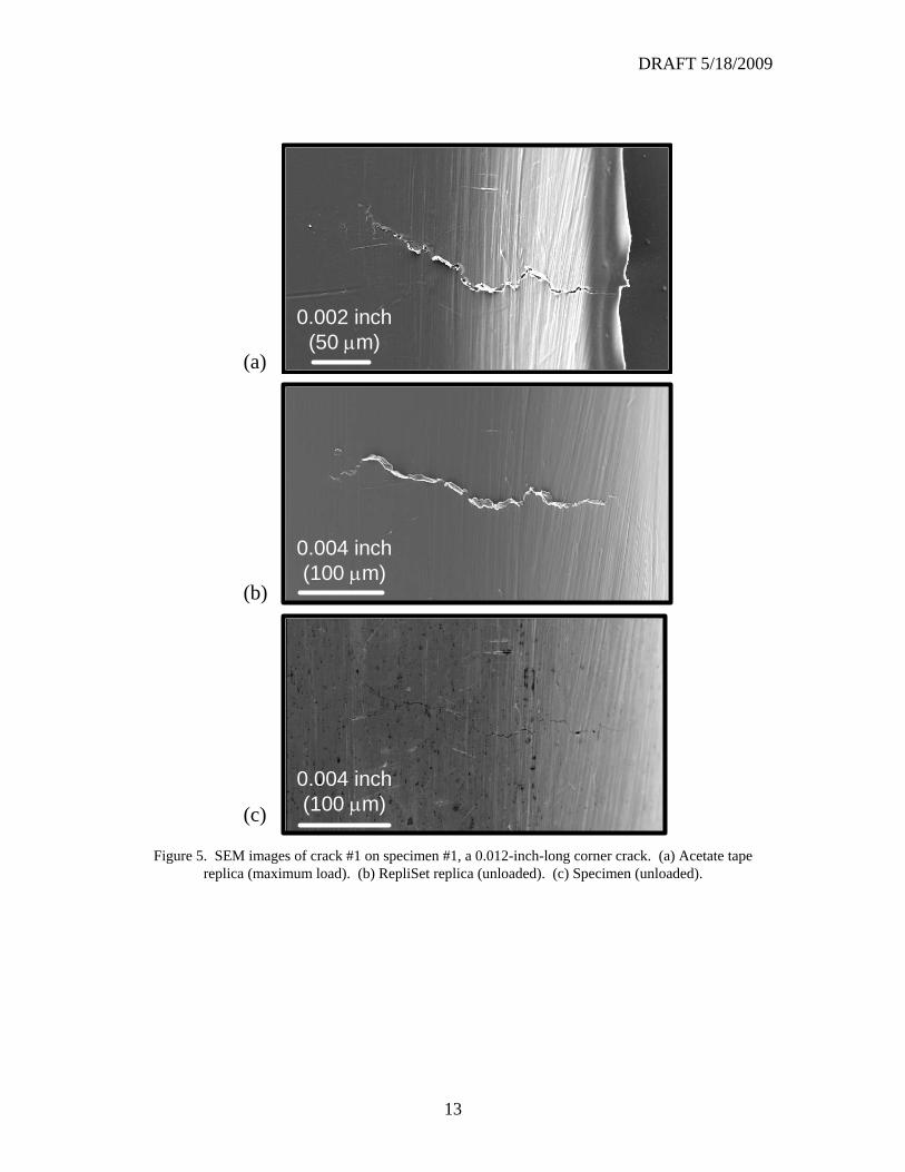
SEM micrographs of crack #1 are shown for an acetate tape replica taken at maximum load (Figure 5a), a RepliSet replica taken at zero load (Figure 5b), and of the actual specimen (Figure 5c) also taken at zero load.5 A qualitative comparison shows that the same subtle crack features appear in all three images. From the acetate tape replica, the crack length was determined to be 0.0110 inches long (280 μm). The result from the RepliSet was 0.0135 inches (343 μm). The crack length from the specimen, somewhat difficult to determine because the crack tip was difficult to locate, was in the range of 0.0093-0.0138 inches (236-350 μm). Here, the RepliSet method, likely handicapped because replicas were taken at zero load, indicated that a longer crack was present than the acetate tape method. This 22% difference suggests that features are shown on RepliSet replicas that were not captured on the acetate tape replicas.
5 Images taken from replicas are mirror images of the actual specimen. For better comparison, images have been flipped such that features on the right-hand-side of the replica images correspond to features on the right-hand-side of the specimen images.

DRAFT 5/18/2009
5
Table 1. Crack length measurements from replicas and specimen examinations.
Images for cracks #2 and #3 are shown in Figures 6 and 7, respectively. For crack #2, the crack lengths determined from the acetate tape (Figure 6a), RepliSet (Figure 6b), and the specimen (Figure 6c) are 0.0032 inch (81 μm), 0.0041 inch (104 μm) and 0.0043 inch (110 μm), respectively. Here, the acetate tape crack determination is approximately 22% less than the RepliSet determination, and both replica measurements are less than the specimen indication. For crack #3, the crack length measurements for acetate tape (Figure 7a), RepliSet (Figure 7b), and the specimen (Figure 7c) are 0.0010 inch (26 μm), 0.0008 inch (20 μm), and 0.0011 inch (28 μm), respectively. Again, the RepliSet crack length measurement is greater than the acetate tape value, but slightly less than from a destructive specimen examination.
Specimen #2 Specimen #2 was fatigue loaded at a notch stress of 160 ksi (R = 0.1). After 115,000 cycles, a
0.005-inch-long surface crack was found. As shown in Figure 8a, crack initiation occurred near the mid-thickness of the slot. This crack is shown at higher magnification in Figure 8b. SEM images of this crack are shown for an acetate tape replica (Figure 9a), RepliSet (Figure 9b), and the specimen (Figure 9c). A comparison of these images reveals that the qualitative features (e.g., shape of the crack) in each image are similar to the other images of the same crack. Comparison of the crack length measurements reveals that the RepliSet measurement of 0.0054 inch (137 μm) is bounded by the acetate tape measurement of 0.0052 inch (132 μm) and the destructive examination value of 0.0056 inch (143 μm).
Similar observations were made for Specimens #3-5 [6], however, for brevity, these results are not presented in this paper.
Crack Length (μm)
Specimen # Crack # RepliSet Acetate Tape Acetate Tape Specimenzero load zero load max load zero load
1 1 343 230 280 3502 104 90 81 1103 26 22 20 27
2 1 137 135 132 143
3 1 170 159 163 1712 218 200 206 2183 170 164 162 1704 201 204 193 2015 211 196 206 2116 45 42 43 457 156 157 149 156
4 1 199 185 183 194
5 1 129 118 131 1402 249 208 226 250

DRAFT 5/18/2009
6
Post-polish crack detection Experimental results show that polishing of cracked surfaces increases the difficulty of crack
detection because material may be smeared over the crack mouth, especially for soft ductile materials such as aluminum. The possibility of something similar occurring in Inconel 718 is worthy of consideration, especially considering that polishing is a proposed method for removal of small cracks. If the RepliSet method is unable to detect existing cracks after slot surfaces are polished, it may be impossible to determine if the crack has been completely removed or is simply undetectable. To determine how polishing affects crack detection, several specimens containing a wide range of crack shapes and sizes were replicated before and after polishing. In all cases, specimens were polished using the flight-hardware-approved method [2] and replicas were taken in the unloaded condition.
Specimen #6 Specimen #6 was fatigue loaded at a notch stress of 160 ksi (R = 0.1) for 64,000 cycles. A
fatigue crack initiated and propagated to become a corner crack measuring 0.039 inches (833 μm) in length on the slot surface and 0.015 inches (380 μm) in length on the side of the specimen. An SEM micrograph (acetate tape replica) of the slot surface is shown in Figure 10a. The crack is seen to have propagated from one corner (region (b)) through nearly 80% of the sheet thickness (to region (c)). Higher magnification images of regions (b) and (c) are shown in Figure 10b and 10c, respectively. Figure 10b reveals that the crack has propagated around the edge on the left. The crack tip is shown in Figure 10c, indicating that the crack has yet to grow to the corner on the right side. Therefore, this crack is identified as a corner crack (i.e., propagated around one corner) rather than a through-thickness crack (i.e., propagated around both corners).
The slot surface was polished, removing approximately 0.002 inches (0.05 mm) of material. The crack can still be detected on a RepliSet replica, as shown in Figure 11a, although the crack is much less pronounced than before. Higher magnification images of the regions labeled (b), (c), and (d) are shown in Figures 11b-d, respectively. The crack can be readily identified from the left-side corner to at least 50% through the sheet thickness (0.025 inches). It is difficult to identify the crack tip and quantify the crack size. However, this crack remains detectable after polishing and is identified as a corner crack. A small crack-like feature is shown in Figure 11d, although no connection is found with the previously mentioned corner crack.
Destructive examination of small cracks
Most engineering analysis of small cracks assume that surface cracks have a semi-circular shape and corner cracks have a quarter-circular shape. It is likely that similar assumptions will be made in fatigue life analyses of the flowliners. To determine if this assumption is reasonable, several specimens containing small cracks were completely fractured to allow an inspection of the crack surfaces. A crack surface image of specimen #1 is shown in Figure 12. Recall that this specimen contained three cracks; a corner crack approximately 343 μm long and two surface cracks, 104 μm long and 26 μm long, respectively. This specimen was completely fractured to expose the surfaces of the corner crack and one of the surface cracks (104 μm long), as seen in Figure 12. A change in morphology separates the surface produced by fatigue from the overload failure and is shown in the figure as a dotted line. The corner crack, seen in the lower right corner of the figure, appears to have the shape expected of a surface crack (semi-circular). Here, the crack length is 343 μm and the crack depth is 176 μm. This is likely because this crack initiated as a surface crack and then propagated to the corner and the fatigue test was stopped before the
DRAFT 5/18/2009
7
crack shape could transition from a semi-circular surface crack to a quarter-circular corner crack. The smaller surface crack, seen in the lower left corner of the figure, is nearly semi-circular with a surface length of 104 μm and a depth of 55μm.
The crack surface of specimen #6 is shown in Figure 13. Recall that specimen #6 contained a large corner crack (833 μm long) and was re-polished after the fatigue test was stopped. Here, the crack shape is nearly semi-circular (crack length of 833 μm and a crack depth of approximately 342 μm) which is typical of a surface crack. This suggests that this crack initiated as a surface crack and had not reached a steady state corner crack configuration (quarter-circular) before the fatigue test was stopped. Considering that the crack surface length was approximately 80% of the sheet thickness, it seems unlikely that a steady state corner crack configuration would have been reached before the crack became a through crack.
Based on crack surface observations, it seems reasonable to assume that the depth of a surface crack is approximately one-half of its surface length. The assumption that the depth of a corner crack is equal to its surface length seems to be inaccurate, but conservative.
Discussion
In this study, multiple cracks were measured using three crack measurement techniques. Crack length determinations were made using (1) acetate tape replicas taken at maximum load (160 ksi notch stress) and on unloaded specimens, (2) RepliSet replicas taken on unloaded specimens, and (3) direct specimen examinations of unloaded specimens. The acetate tape replica method is known to give acceptable results, and crack detection should be enhanced because replicas were taken under tensile loading conditions. Despite the perceived advantage of tensile loading, crack length values determined from acetate tape replicas were consistently shorter than the RepliSet values. This suggests that the loading state is not critical for crack detection. There was only a single exception to this observation for each of the 14 cracks analyzed. This suggests that some near-crack-tip features that are transferred to the RepliSet replicas are not reproduced on the corresponding acetate tape replicas. Of the 14 cracks observed on these specimens, one was 0.002 inches (50 μm) long and two were 0.005 inches (125 μm) long. Although no probability of detection study has been conducted for the RepliSet method, clearly this method can reliably be used to locate cracks well below the accepted NDE threshold (0.075 inches; 1.9 mm). Pit-like flaws, a typical surface defect on flowliner slots, as small as 0.001 inch have been observed even at relatively low magnification (50X-100X).
A significant advantage of the RepliSet method is that information regarding the damage mode (e.g., crack, pit-like surface flaw, scratch, etc.) and the location of the damage are readily obtained. It has been shown that this method can distinguish between crack damage and pit-like surface flaws [6]. Although not discussed in this paper, other forms of slot surface damage can be determined including scratches, tool marks, dents, etc. Additionally, by preserving the orientation information with each replica, information is available about the damage location and configuration. For example, in the case of crack damage, information about the location on the slot surface and the crack configuration (e.g., through-thickness crack, corner crack, or surface crack) was available.
The results shown in Figures 10 and 11 indicate that cracks are more difficult to detect following polishing of the slot surfaces. Small surface cracks become detectable as tensile

DRAFT 5/18/2009
8
loading is applied to the specimen, and these cracks remain detectable even after the specimen is unloaded again.
Specimens containing fatigue cracks were destructively examined to determine the aspect ratio of small cracks in this material. The depth of surface cracks was approximately one-half of the surface length, but the depth of corner cracks was significantly shorter than the surface length, likely due to the fact that the cracks observed were transforming from surface cracks to corner cracks. The assumption that the depth of corner cracks is equal to the surface length would be conservative.
Summary
A feasibility study has been conducted to determine if RepliSet, a surface replication method, is a practical way to characterize damage found at space-shuttle main-engine LH2 flowliner slots. Experimental testing was performed on coupon specimens that simulate the stress state at flowliner slots, and results have shown that the RepliSet method is at least as reliable as another well-established replication method (acetate tape). On five specimens discussed in this paper, fourteen cracks ranging from 0.002 inches (50 μm) long to 0.008 inches (200 μm) long were found using RepliSet. The crack length determinations obtained from the RepliSet method were nearly the same as that from a direct examination of the slot surface. In quantitative terms, the RepliSet method was able to consistently detect cracks as small as 0.005 inches (125 μm) long and pit-like surface defects as small as 0.001 inches (25 μm) long. Crack detection was more difficult after polishing cracked surfaces, but results show that through-thickness cracks and corner cracks can still be detected, and cracks can be detected after tensile loading is applied to the specimens.
References
1. J.A. Newman, S.W. Smith, S.A. Willard, and R.S. Piascik, “A Comparison of Weld-Repaired and Base Metal for Inconel 718 and CRES 321 at Cryogenic and Room Temperatures,” NASA/TM-2004-213253, ARL-TR-3266.
2. J.C. Melcher and D.A. Rigby, “Analysis and Repair of Cracks in the Space Shuttle Main Propulsion System Propellant Feedlines,” Proceeding of the 39th AIAA/ASME/SAE/ASEE Joint Propulsion Conference and Exhibit, 20-23 July 2003, Huntsville, Alabama, AIAA 2003-4609.
3. M.H. Swain, R.A. Everett, J.C. Newman, Jr., and E.P. Phillips, “The Growth of Short Cracks in 4340 Steel and Aluminum-Lithium 2090,” AGARD Report No. 767, Short-Crack Growth Behavior in Various Aircraft Materials, August 1990, Advisory Group for Aerospace Research and Development.
4. Small-crack Test Methods, J.M. Larsen and J.E. Allison, Eds., ASTM STP 1149, American Society for Testing and Materials, Philadelphia, PA, 1992.
5. Small Fatigue Cracks, R.O. Ritchie and J. Lankford, Eds., American Institute of Mining and Metallurgical Engineers, Warrendale, PA, 1986.
6. J.A. Newman, S.A. Willard, S.W. Smith, and R.S. Piascik, “Flow Liner Slot Edge Replication Feasibility Study,” NASA/TM-2006-213921, ARL-TR-3638.

DRAFT 5/18/2009
9
Figure 1. The flowliner locations on the space shuttle orbiter are shown in a series of photographs. (a) Orbiter aft end shown with main engines removed. (b) LH2 feedline is shown in the main engine orifice.
(c) Flowliners are shown inside the LH2 feedline. (d) Flowliner slots.
Upstreamflowliner
Engine #1
LH2 feedline
Engine #2 Engine #3
Downstreamflowliner
UpstreamFlowliner slots
DownstreamFlowliner slots
(a) (b)
(c) (d)

DRAFT 5/18/2009
10
Figure 2. Drawings of the slotted specimen configurations used in this study. (a) Double-edge notch specimen. (b) Center-slot specimen.
3 inch
12 inch
1 inch0.5 inch
0.25 inch
2.5 inch
(a) Double-edge notch specimen (b) Center-notch specimen

DRAFT 5/18/2009
11
Figure 3. SEM images of crack #3 on specimen #3. (a) Acetate tape replica. (b) First RepliSet replica. (c) Fifth RepliSet replica.
0.002 inch(50 μm)(a)
(b)
(c)
0.002 inch(50 μm)
0.002 inch(50 μm)

DRAFT 5/18/2009
12
Figure 4. SEM images of specimen #1 acetate tape replica. (a) Low magnification. (b) High magnification of region containing cracks #2 and #3.
Crack #1 – 0.014 inch(343 μm)
0.008 inch(200 μm)
Specimen Edge
Specimen Edge
Region containingCracks #2 and #3
Crack #3 – 0.001 inch (26 μm)
Crack #2 – 0.004 inch (104 μm)
0.004 inch(100 μm)
Specimen Edge
(a)
(b)
DRAFT 5/18/2009
13
Figure 5. SEM images of crack #1 on specimen #1, a 0.012-inch-long corner crack. (a) Acetate tape replica (maximum load). (b) RepliSet replica (unloaded). (c) Specimen (unloaded).
0.002 inch(50 μm)
0.004 inch(100 μm)
0.004 inch(100 μm)
(a)
(b)
(c)

DRAFT 5/18/2009
14
Figure 6. SEM images of crack #2 on specimen #1, a 0.004-inch-long surface crack. (a) Acetate tape replica (maximum load). (b) RepliSet replica (unloaded). (c) Specimen (unloaded).
0.0008 inch(20 μm)
(a)
(b)
(c)
0.0008 inch(20 μm)
0.0008 inch(20 μm)

DRAFT 5/18/2009
15
Figure 7. SEM images of crack #3 on specimen #1, a 0.001-inch-long surface crack. (a) Acetate tape replica (maximum load). (b) RepliSet replica (unloaded). (c) Specimen (unloaded).
0.0002 inch(5 μm)
0.0004 inch(10 μm)
(a)
(b)
(c)
0.0004 inch(10 μm)

DRAFT 5/18/2009
16
Figure 8. SEM images of specimen #2 acetate tape replica. (a) Low magnification. (b) High magnification of the region containing a 0.005-inch-long surface crack.
0.008 inch(200 μm)
0.0008 inch(20 μm)
Specimen Edge Specimen Edge
Region containing0.005 inch (125 μm) crack(a)
(b)

DRAFT 5/18/2009
17
Figure 9. SEM images of the 0.005-inch-long surface crack on specimen #2. (a) Acetate tape replica (maximum load). (b) RepliSet replica (unloaded). (c) Specimen (unloaded).
0.0008 inch(20 μm)(a)
(b)
(c)
0.0008 inch(20 μm)
0.0008 inch(20 μm)

DRAFT 5/18/2009
18
Figure 10. SEM images of specimen #6 before polishing (unloaded). (a) Low magnification. (b) High magnification image of region (b). (c) High magnification image of region (c).
0.008 inch(200 μm)
(b) (c)
(a)
(b)
(c)
{{
0.002 inch(50 μm)
0.002 inch(50 μm)

DRAFT 5/18/2009
19
Figure 11. SEM images of specimen #6 after polishing (unloaded). (a) Low magnification. (b) High magnification image of region (b). (c) High magnification image of region (c). (d) High magnification of
region (d).
(b)(c)
(a)
(b)
(c)
{{(d) {
(d)
0.008 inch(200 μm)
0.008 inch(200 μm)
0.008 inch(200 μm)
0.008 inch(200 μm)

DRAFT 5/18/2009
20
Figure 12. SEM micrograph of crack surfaces for specimen #1.
Figure 13. SEM micrograph of crack surface for specimen #6.
0.008 inch(200 μm)
0.014 inch(343 μm)
0.007 inch(176 μm)
0.004 inch(104 μm)
0.002 inch(55 μm)
0.008 inch(200 μm)0.033 inch
(833 μm)
0.014 inch(342 μm)