report 1 - defense technical information center · 17. distribution statement ... radiography...
TRANSCRIPT

UNCLASS IFIED _____
SECURITY CLASSIFICATION OF TNIII P'AGE (Whar, Date Rnfo.,.Q
REPORT DOCUMENTATION PAGE R~)T!TUTOSj ~ 1* R N UMBER2 GOVT ACCESSION NO. 3. RECIPIENT'S -ATA LOG HUMMER
TdP-4-2-811 L_____1____00_____
ST OPM TEST AND EVALUATION COMMAN ia dMEASUREM4ENT OF PROJECTILE RATE OF SPINp a'S PERFORMING ORG. OEOR FUME
S. CONTRACT OR GRANT NUMBER(s)
9. PERFORMING ORGANIZATION NAME AND ADDRESS 10. PROGRAM ELEMENT. PROJECT, TASK
AREA & WORK UNIT NUMBERSUAryAberdeen Proving Ground, Maryland 2100
Aberdeen Proving Ground, Maryland 21005
14. CONITROLLING AGENCY NAME AN ADDRESS.IIn 12ce RiS SURTY LS.11di ~,
14. MONITORINGTAGNNSTATEMENT AO t lhgOf)I. EUIYCAS (of this reportSC)DUL
Approed fo publc relase;distrbutiosunliited
I 11k
17. DISTRIBUTION STATEMENT (of thm. abstract mniit.,.di BlocI~k 20. 11 dIfformnt flu., R
IS. SUPPLEMENTARY NOTES
IS. KEY WORDS (Coninume on revere sid It necoemy an~d Idendtir by block nsmbor)
Projectile *Yaw Cards*SabotN
rSpin *New
1%A@SrACT (Clod~aw - a'u M abe oft% p N mfseFsid timdflr 6r. black n~mbw) 1Provides techniques for measuring projectile spin rate. Includes photographicmethod, paint smear method, pop-out-pin method, radio telemetry method,magnetic spin loop methdd (applicable to magnetizable projectiles),,and flashradiography method (applicable primarily tc aluminum sabots at time ofemergence from gun tube). Includes spin rate computations for all( methods.
DDO M M0 OTION0OPIN*SV655 OS6fLWTM UNCLASSIFIED '5•SCCUMY CLASNFICATI 0 OF rhIS PAG Ut.DtaIa5UM5S~~~~~,= I'D55 -F7!1IF"- .~ ~ ~

US ARMY TEST AmD EVALUATION COm(ANDTEST OPERATIONS PROCEDUTRE
DRSTE-RP-702-103 12 February 1976Test Operations Procedure 4-2-811AD No.
MEASUREMENT OF PROJECTILE RATE OF SPIN
Paragraph 1. SCOPE ........... .................. 12. FACILITIES AND INSTRUMENTATION . . . . 1 13. PREPARATION FOR TEST .............. 24. TEST CONTROLS . .. .. . . . . . . . . . 25. SPIN RATE TESTS ....... ............. 25.1 Photographic Method ................. 35.2 Paint Smear Method ...... ........... 65.3 Pop-Out-Pin Method ...... ........... 85.4 Radio Telemetry Method ..... ......... 85.5 Magnetic Spin Loop Method. . . . . . . . 95.6 Flash Radiography Method . . . . . . . .11
1. SCOPE. This TOP describes the methods used at Army proving groundsto measure the rate of spin of projectiles. Photographic, mechanical,and electronic techniques are included.
2. FACILITIES AND INSTRUMENTATION.
2.1 Facilities.
ITEM REQUIREMENTS
Test site Firing range with unrestricted viewof, and access to, the targets.
Yaw card stands To support yaw cards and otherequipment items in the line of fire.
Detector loop support Fabricated as illustrated underpara 5.5.1.
Pop-out pins for projectiles As described in para 5.3.1.2.2 Instrumentation. •
ITEM MAXIMUM ERROR OF MEASUREMENTI
Photographic equipment Spin rate (rps); t2%(as described in para 5.1 "and TOP/MTP 4-2-816)
1-See note on p. 2.-
*This TOP supersedes MTP 4-2-811, 1 November 1966.
Approved for public release; distribution unlimited,
II"v r
TOP 4-2-811 .2 February 1976
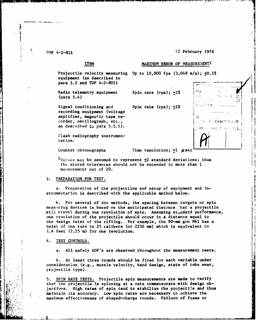
ITEM MAXIYIUM ERROR OF MEASUREIENT 1
Projectile velocity measuring Up to 10,000 fps (3,048 m/s); ±0.1%equipment (as described inpara 5.2 and TOP 4-2-805)
Radio telemetry equipment Spin rate (rps); ±2% 7,11(para 5.4) . ,
Signal conditioning and Spin rate (rps); ±2% ........recording equipment (voltage ......amplifier, magnetic tape re-corder, oscillograph, etc., :'as described in para 5.5.1). L
Flash radiography instrumen-L tation.
Counter chronographs Time resolution; ±1 psI c 5
'Values may be assumed to represent ±2 standard deviations; thusthe: stated tolerances should not be exceeded in more than 1 ;measurement out of 20.
3. PREPARATION FOR TEST.
a. Preparation of the projectiles and setup of equipment and in-
strumentation is described with the applicable method below.
b. For several of the methods, the spacing between targets or spinmeasiiring devices is based on the anticipated distance 'hat a projectilewill travel during one revolution of spin. Assuming st.adard performance,one revolution of the projectile should occur in a distance equal tothe design twist of the rifling. For examle, the 90-mam gun M41 has a
•I twist of one turn in 25 calibers (or 2250 mm) which is equivalent to7.4 feet (2.25 m) for one revolution.
4. TEST CONTROLS.
a. All safety SOP's are observed throughout the measurement tests.
b. At least three rounds should be fired for each variable under1 ,consideration (e.g., muzzle velocity, band design, state of tube wear,
projectile type).
5. SPIN RATE TESTS. Projectile spin measurements are made to verifythat the projectile is spinning at a rate commensurate with design ob-jectives. High rates of spin tend to stabilize the projectile and thus
,, maintain its accuracy. Low spin rates are necessary to achieve the
-. . - ~maximum effectiveness of shaped-charge rounds. Failure of fuzes or

12 February 1976 TOP 4-2-8.11
4 other components may result from excessive spin velocity, whereas failureto arm may result from low spin velocity.
Spin measurements are most important in connection with tests to assurethat rotating bands are engraving properly and maintaining their in-tegrity, and in tests of projectiles that have sabots or carriers thatare expected to impart a certain spin to the core of the projectile.
Spin rates are usually reported in terms of revolutions per second.Timing data are obtained either by direct recording of timing marks onfilm records or calibration of the time from velocity data obtained byconventional measurement of projectile velocities (TOP 4-2-805).
5.1 Photographic Method. The selection and deployment of photographicinstrumentation depends on the test requirements and the anticipatedperformance of the test item. The various types of photographic instru-menttionthat can be used are described in TOP/MTfP 4-2-816.
5.1.1 Procedure. Cameras are placed along the line of fire to obtainphotographs of the projectile in flight at two or more points on thetrajectory. A spiral pattern is painted (in contrasting color) on theprojectile so that the change in the rotational position during thetime elapsed between photographs can be determined. The time lapse isdetermined either from co mn-coded time impressed on the filin or from
the velocity of the projectile and the distances between ce~deras. TheI ~amount of rotation, expressed in revolutions, divided by the elap~iedtime, in seconds, gives the spin rate in revolutions per second.ii At least three cameras are required to provide adequate data. Thefirst camera Is usually placed as close as possible to the waapon, but not
so close as to risk obscuration by smoke or flame. The second camerais so located that less than one complete rotation of the projectile(para. 3b) will occur between it and the first camera. The third camerais placed downrange at a distance that permits about five revolutions ofbehe projectile between It and the first camera. Additional cameras maybeused to increase the accuracy and precision of measurement. The
distances between the cameras are measured to the nearest 0.05 foot
(0.015 meter). All cameras are aligned so that their optical axes areperpendicular to the trajectory.
E Spin rates are most frequently measured by the use of "smear" cameras,[ which have their lateral fields of view restricted by an internal slit.These cameras must have a film velocity approximately equal to the ve-locity of the Image, and must be located so that the direction of filmtravel irn the camera will be oppoj.ite that of the projectile to com-pensate for image reversal by the optical system. If motion picturecameras are used, the shutter speeds and framing razes should be adequateto provide relatively sharp images. Supplemental lighting may be ob-
() tained with flash lamps.
i i
TOP 4-2-811 1? February 1976
Still cameras must be used in darkness, in inclosed ranges, or in "darkboxes." Microflash techniques may be used to obtain adequate lightingtinder these conditions. The projectile is momentarily illuminated asit passes through the camera field, and the shutter opening is synch-ronized with the illumination. By using cameras with self-processingfilm, immediate examination of the photograph is possible.
The spiral pattern mentioned above must go completely around the pro-jectile, and the ends of the pattern must be plainly marked to be visiblein all rotational positions of the projectile. The change in rotationalposition occurring between two camera stations can be inferred from thechange in the appearance of the spiral pattern in the photographic image.The progression of the spiral, as seen in the photograph, is usuallymeasured with respect to the longitudinal axis of the projectile, and acomplete revolution appears as a complete longitudinal progression of thespiral. For ease of data reduction the spiral should be designed sothat the amount of rotation is proportional to the amount of progressionof the spiral. A spir:l etencil suitable for use on the cylindrical por-tion of a projectile can be simply designed by cutting from paper orother flexible material a right triangle with one leg equal to the cir-cumference of the projectile and the other slightly shorter than thelength of Lhe cylindrical portion. The latter side is placed parallel
Lk to the longitudinal axis and the triangular piece wrapped around the cy-linder. (Fig. 1 illustrates such a pattern.) The pattern should be asiilong as possible to give better precision of the measurement of rate ofspin.
S5.1.2 Spin Rate Computation.
5.1.2.1 Spin Rate from Camera Observations: A first approximation ofthe spin rate is obtained from observations made by the two cameras so
H placed that less than one revolution of the projectile occurs betweentI them. The partial revolution is calculated by determining the difference
in the spiral positions recorded by the two cameras. Figure I (a and b)illustiates the appearance of the spiral as recorded by cameras 1 and2, camera 1 being nearer the weapon. Assuming clockwise rotation ofthe projectile, the partial revolution, AR, is given by the equation:
dl - d2AR- L
Th spin rate, r, in revolutions per second, is given by the equation:
ARr A
where At (seconds) is the time between the two observations.
4

¶ I
12 FeLruary 1976 TOP 4-2-811
Longitudinal Axis- ....of .ojeotile
A dl
L --L
a. Image of Spiral From Camera No. 1
Longitudinal Axisof Projectile
b. Image of Spiral From Camera No. 2
Long tudinal Axisof Projectile
[ ' d3
c. Image of Spiral From Caawera No. 3
Figure 1. Views of Painted Spirals from Three Cameras.
A more precise determination of the spin rate is had by combiningdata from the third camera (c, fig. 1) with data from the first two.Because the expected error of measurement (random error) varies inverselywith At, use of the longer time between the observations made by cameras1 and 3 (or 2 and 3) improves the accuracy of the measurement of rate
of spin. Calculations are as follows:
'• , -.. 5

S TOP 4-2-81.1 12 February 1976
The elapael time between observations by cameras.1 and 3 is de-noted by A't. The number of complete revolutions, n, is found by multi-plying the spin rate calculated from cameras 1 and 2 by A't and discard-ing the fractional portion of that product. The appropriate fraction ofa revolution, AKR, is obtained frois measurements of the photographstaken by caueras 1 and 3 (fig. 1).
A'R dl -d3
L
The spin rate is then calculated as
n + A'RAlt
This procedure is easily extended for application to a situationin which mote than three cameras are used. The accuracy obtained bythese photogxaphic methods is within about 2 percent, depending on thesharpness and contrast in the film image.
5.1.2.2 Theoretical Spin Rate: It is sometimes of interest to compare
the measured spin rate with the theoretical spin rate for monobloc pro-
jectiles. Consider the 90-mn gun of paragraph 3b (which gave a spindistance of 7.4 feet (2.25 m) for one revolution). If a velocity of3000 fps (91.4.4 m/s) is assumed, the rate of spin for a monobloc projectilewould theoretically be 3000/7.4 (914.4/2.255) or 405.4 revolutions persecond when the projectile emerges from the tube.
5.2 Paint Smear Method.
5.2.1 Procedure. The spin rates of p'ojectiles fired from rifled tubesmay be obtained WiLh a relatively simplh setup. This method, which hasyielded satisfactory spin data for 90-mm guns, requires minimal datareduction and is comparatively inexpensive.
The windshield or ogive of the projectile is painted with a slowdrying oil paint (red, blue, or green) as shown in figure 2.
One-Eighth of
Circumference
Figure 2. Painting of the Projectile Ogive.
6

t I12 February 1976 TOP 4-2-811
Three cloth panel targets 4 feet square, and velocity coils or skyscreens (TOP 4-2-805) are positioned as shown in Figure 3. Spacing shouldbe controlled to within 0.05 foot. Dimension a (gun to first coil) anddimension f (first to second coil) may be selected to suit the velocitydetermination. Dimensions c and 4 are limited to encompass slightly
less than one revolution (para 3b) between panels 1 and 2 and slightlyless than two revolutions between panels 2 and 3. Dimensions b and eare not critical and may be varied to facilitate the test setup.
S" So3reen (r Velocity Coils)
Cloth Paxsla
6 17Figure 3. Target Spacing.
At least three rounds are fired for each variable under consideration:
i.e., muzzle velocity, band design, state of tube wear, projectile type,or other feature. Velocity should be determined for each round.
A. the roundpasses through the cloth target, a clear red, blue, or greenarea will be stenciled on the cloth by the painted portion of Lhe ogive.The angular orientation will change from target to target because of thespin of the projectile, as indicated in figure 4.
L 91 03
Target 1 Tar•pt 2 Target
Figure 4. Stenciled Target.
7

TOP 4-2-811 12 February 1976
5.2.2 Spin Rate Computation. In computing spin, the projectile rotation(0) between panels is determined first by means of a protractor, wherefor clockwise rotation 0- 02- 01' (If the algebraic sum is negative, add 3600.)
The distance between targets in feet (or meters) (d) divided by the ve-locity of the projectile between the coils (v') gives the time of flight(td) between the targets in seconds.
The rate of spin (rps) is equal to the number of revolutions the pro-jectile makes between the targets divided by the time of flight betweenthose targets. The rate of spini between panels 1 and 2, 2 and 3, and 1and 3 should check and may be averaged. The longer time base betweenpanels 1 and 3, however, should produce the more reliable data.
When spin measuremenzs are made at some distance from the muzzle of thegun, the assumption muat be made that there is a linear relationshipbetween projectile spin rate and velocity. Since the decrease in spinrate and velocity from drag forces may not be proportional, the measure-ments made at considerable distances downrange are not reliable forpredicting initial rate of spin. In general, if measurements are madewithin several hundred feet of the muzzle, the rate of spin will not beappreciably affected.
5.3 Pop-Out-Pin Method.
5.3.1 Procedure. A method that is occasionally used to determine spinrate involves the use of a modified projectile fitted with pop-outpins. Centrifugal force causes these pins to extend beyond the normalcircumference of the round and to notch yaw cards as the round passesthrough them. The test setup is the same as that used for the paintsmear method (para 5.2) except that cardboard yaw cards are used in theline of flight instead of cloth panels. The angular change of notch
rJ orientation from taiget to target and the velocity of the projectiledetermine the spin rate.
5.3.2 Spin Rate Computation. Spia rate computation is the same as that
described for the paint smear method (para 5.2).
5.4 Radio Telemetry Method.
1 5.4.1 Procedure. An electrical system for measuring spin rate that maybe used when other methods are not suitable is a spin-sonde operating inthe vwry high frequency radio range. This method is particularly suitedfor measurement of continuous or terminal spin rates. The airborne por-tion of the system consists simply of a miniature radio transmitter and
a polarized transmitting antenna. The antenna is usually a small loopalthough a dipole may be used. The receiving antenna is usually oriented

12 February 3976 TOP 4-2-811
to collect the maximum signal from the transmitter. Assuming that thereceiving antenna is polarized in the horizontal plane, the maximum sig-nal will be received when the transmitter antenna is also polarizedhorizontally. Minimum signals will be received when the antenna are outof phase. An AM receiver, tuned to the transmitter frequency, will pickup a signal varying in strength and modulated by the spinning antenna ofthe transmitter. This signal is recorded by magnetic tape and/or oscillo-graph for data reduction purposes. The projectile spin rate is directlyrelated to the signal from the radio receiver, the actual spin rate beingone-half the demodulated audio frequency.
5.4.2 Spin Rate Computation. The spiu rate data recorded on magnetictape are processed through an analog computer to determine the audio fre-quency. The spin rate of tbr projectile is equal to one-half the de-modulated audio frequency. Spin rate can also be determined by developingand processing the :scillographic record.
5.5 Mag••ic Spin Loop Method. The magnetic spin loop is an economical,relinble, and accurate method of obtaining spin data on magnetizabler rojectiles having a velocity/spin ratio of less than 50 feet per revo-lution (15.24 m/rev).*
5.5.1 Procedure. Spin rate is obtained using a transversely magnetizedprojectile and a detector loop (fig. 5) consisting of a single loop ofwire supported along the line of fire. Support for the loop is providedby two parallel beams (two-by-foura) that are supported aboveground byvertical uprights or yaw card stands. The projectile is fired parallelto and approximately 1 foot above the detector loop. As the projectiletravels over the loop, a spin signal is induced in the loop by the mag-netic field of the spinning projectile. This signal i3 fed to a voltageamplifier whose output is recorded on magnetic tape along with a timingsignal on a second channel of the tape. The recorded signals are playedback to a galvanometer oscillograph us'.ng direct-point recording paper.A reduced playback speed is used to provide a time-expanded plot (fig. 6)for measurement.
5.5.2 Spin Rate Computation. Spin rate is determined from the oscillo-graphic record (fig. 6) of the time-expanded signals. Spin is recordedas a continuous sine wave with the distance between each peak .epreserLtingone revolution of spin. The revolutions of spin are compared with therecorded timing signal to obtain the time per revolution which is thenconverted to revolutions per second.
*Savage, Michael R., "Study to Improve Spin Data Acquisition," JeffersonProving Ground, Madison, IN, Report MTD-I-1-74, TECOM Project 9-C0-004-000-005, June 1974 and Report MTD-I-4-75, TECOM Project 9-CO-014-000-007,May 1975.
9

* TOP 4-2-811 12 February 1976
Yaw Card
q j / 50,
°ii
ii
-31
Detector }To InstrwuentationLoop Wire
Figure 5. Typical Detector Loop Support.
10 ko li''Time Base
4 10
- . - - -,- -_..-

I,.1
12 February 1976 TOP 4-2-811
5.6 Flash Radiograrhy Method. Flash radiography (TOP/MTP 4-2-825) isused primarily for measuring the rate of spin of aluminum or other non-magnetic sabots just as they emerge from the gun tube. (The nonmageticmetal and thf. obscuration from muzzle flash prevent the use of other methods.)
If subproj~ctile spin must also be measured, t magnetic spin loop may be used.
5.6.1 Procedure, A small lead pin is inserted off center in the base ofthe sabot, and the complete round is loaded in the chamber of the weapon.The projectile is oriented so that the twist of the rifling will causethe pin to be positioned on the longitudinal axis of the round as itexits the tube. The rotational position of -the pin is recorded withrespect to time by two X-ray units located along the flight path nearthe muzzle. One unit is positioned to record the pin location when theround isi approximately 2 inches from the muzzle, and the second unit ispositioned so that one-quarter of a revolution of the round (para 3b)will occur between it and the first X-ray unit. Triggering of the X-rayunits is initiated by a strain gage on the tube of the weapon withsuccessive pulses controlled by a time-delay network. Time-delay settingsare calculated from muzzle velocity data. A counter chronograph is usedto record the time between the X-ray unit triggering pulses.
5.6.2 Spin Rate Computation. The time for one revolution of spin isdetermined from the angle through which the pin has rotated (as viewedCn the X-ray film) during the recorded tim: between tr.ggering pulses.This value is then converted to revolutions per second.
Recommended changes to this publication should be forwarded toCommander, U. S. Army Test and Evaluation Command, ATTN:DRSTE-ME, Aberdeen Proving Ground, MI. 21005. Technical infcr-mation may be obtained from the preparing activity: Commander,U. S. Army Aberdeen Proving Ground, ATTN: STEAP-MT-M, AberdeenProving Ground, Md. 21005. Additional copies are available fromthe Defense Documentation Center, Cameron Station, Alexandria,'Ia,. 22314. This document is identified by the accession number(AD No.) printed on the first page.
J 14.