report: 3 copies research on evaluating synthetic …
TRANSCRIPT

MU
HA
MM
AD
ZU
LH
ILM
I BIN
AB
DU
L R
AH
MA
N
B.E
NG
. (HO
NS
) PE
TR
OL
EU
M E
NG
INE
ER
ING
JAN
UA
RY
2012
RESEARCH ON EVALUATING SYNTHETIC HTHP FLUID
LOSS REDUCER IN VARIOUS OIL BASE DRILLING
FLUIDS
MUHAMMAD ZULHILMI BIN ABDUL RAHMAN
PETROLEUM ENGINEERING
UNIVERSITI TEKNOLOGI PETRONAS
JANUARY 2012
REPORT: 3 COPIES

RESEARCH ON EVALUATING SYNTHETIC HTHP FLUID LOSS
REDUCER IN VARIOUS OIL BASE DRILLING FLUIDS
BY
MUHAMMAD ZULHILMI BIN ABDUL RAHMAN
PETROLEUM ENGINEERING
11566
DISSERTATION REPORT SUBMITTED IN PARTIAL FULFILMENT OF
THE REQUIREMENT FOR THE
BACHELOR OF ENGINEERING (HONS)
(PETROLEUM ENGINEERING)
JANUARY 2012
UNIVERSITI TEKNOLOGI PETRONAS
BANDAR SERI ISKANDAR
31750 TRONOH
PERAK DARUL RIDZUAN


CERTIFICATION OF APPROVAL
Evaluation on Performance of HTHP Fluid Loss Reducer in various Base-Oil
by
Muhammad Zulhilmi Bin Abdul Rahman
11566
Supervisor: Ms. Raja Rajeswary Suppiah
A project dissertation submitted to the
Petroleum Engineering Programme
Universiti Teknologi PETRONAS
In partial fulfilment of the requirement for the
Bachelor of Engineering (Hons)
(Petroleum Engineering)
Approved by,
_____________________
(Raja Rajeswary Suppiah)
UNIVERSITI TEKNOLOGI PETRONAS
TRONOH, PERAK
January 2012

CERTIFICATION OF ORIGINALITY
This is to certify that I am responsible for the work submitted in this project, that the
original work is my own except as specified in the references and acknowledgements,
and that the original work contained herein have not been undertaken or done by
unspecified sources or persons.
____________________________________
(Muhammad Zulhilmi Bin Abdul Rahman)
Bachelor of Engineering (Hons) Petroleum Engineering
Tel: +609-8586394 (D/L); +019-5258268 (H/P)
Email: [email protected]

i
ABSTRACT
Nowadays every company in oil and gas industries is focusing in deep water well
technology. Those who dominate these technologies upfront will conquer this industry
and that is how its work. Basically, deep water well drilling need drilling fluids that can
withstand in HTHP conditions and oil base will be the selection of the drilling fluids
rather water base drilling fluids. One of the additives in oil base drilling fluids is HTHP
fluid loss reducer that functions as small particles that bridging the pore opening in
mudcake to reduce mud filtrate. Research work on performance of synthetic HTHP fluid
loss reducer in various types of oil base mud have a solid objective which is to evaluate
the performance of various types of HTHP fluid loss reducer in various types of oil base
mud. By using four different types of synthetic oil base which are Sarapar 147, Saraline
185, and Escaid 110 the research will be done in terms of evaluating and comparing the
performance each of these synthetic oil base as its rheology properties and behaviors in
HTHP conditions and the performance each of its when applying different types of
HTHP fluid loss reducer which includes of Confi-Trol F and Confi-Trol XHT. The data
collected from the experiments, will then lead to the formulating new HTHP fluid loss
reducer as a new innovation in this area. It seems to have commercial value in this
projects and one of the oil and gas company are willingly to involve in consulting the
project.

ii
ACKNOWLEDGEMENTS
In the name of Allah, the Most Gracious, the Most Merciful. Praise to Him the
Almighty that in His will and given strength, author managed to complete the Final Year
Project I and II in partial fulfilment of the requirement for the Bachelor of Engineering
(Hons) in Petroleum Engineering at Universiti Teknologi PETRONAS.
Special and heartfelt thanks to author‟s beloved Supervisor, Ms. Raja Rajeswary
Suppiah for the valuable guidance and advice. No word could possibly describe how
indebted the author was to his supervisor. Enlightening and countless hours spent in
sharing his insightful understanding, profound knowledge and valuable experiences, he
inspired the author greatly to partake in Oil and Gas Industry in the future especially in
PETRONAS. Without her help, the author would face a great difficulty in completing
this project.
Deepest gratitude also goes to the names below, who‟s continuous support, and
proactive leadership have truly been a great inspiration to author.
Mr. Vickneswaran Veloo, Head-Technical Services of Scomi OilTools
All staffs of Scomi OilTools Global Research Technology Center (GRTC)
Thanks also go to all Universiti Teknologi PETRONAS‟s staff‟s especially lab
technologists from block 15 that were so helpful and their warm supports had made this
final year project a memorable and an informative one. Not to forget, to all lecturers and
friends who have directly or indirectly lent a helping hand here and there. Finally, an
honourable mention goes to author‟s families and friends for their understandings and
supports in completing this project. Without helps of the particular that mentioned
above, author would face many difficulties while doing this project.
______________________________
(Muhammad Zulhilmi Bin Abdul Rahman)

iii
TABLE OF CONTENTS
ABSTRACT i
ABBREVIATION
CHAPTER 1: INTRODUCTION
vi
1.1 BACKGROUND OF STUDY 1
1.2 PROBLEM STATEMENT 2
1.3 PROJECT OBJECTIVES 3
1.4 SCOPES OF PROJECT 4
1.5 FEASIBILITY ANALYSIS 4
1.6 RELEVANCY OF PROJECT 5
CHAPTER 2: LITERATURE REVIEW
2.1 INTRODUCTION 6
2.2 DRILLING FLUID 6
2.3 BASE OIL 8
2.3.1 Base Oil 8
2.3.2 OBMs Base Chemistry 9
2.4 HTHP FLUID LOSS REDUCER 10
2.4.1 Asphalt / Gilsonite 11
2.4.2 Pliolite 11
2.5 RESEARCH PAPER 12

iv
CHAPTER 3: METHODOLOGY
3.1 RESEARCH METHODOLOGY 13
3.2 PROJECT ACTIVITIES 14
3.2.1 Procedure of OBMs Preparation 14
3.2.2 Experiments For Analyzing The Differences Of Rheology
Properties Of Different Types Of OBM
15
3.2.3 Experiments For Evaluating The Performance Of OBM In
Constant Elevated Temperature And Pressure
19
3.2.4 Experiments For Evaluating The Performance Of OBM With
Different Types Of HTHP Fluid Loss Reducer
19
3.2.5 Evaluation On The Results Obtained From Several
Experiments
21
3.3 GANTTCHART 22

v
CHAPTER 4: RESULT AND DISCUSSION 24
4.1 RESULT 24
4.1.1 Initial properties 26
4.1.2 After ageing properties 27
4.1.3 Result analysis 28
4.2 DISCUSSION 34
CHAPTER 5: CONCLUSION 37
REFERENCES 38
APPENDICES vi

vi
ABBREVIATION
List of abbreviation:
OBM Oil Based Mud
SBM Synthetic Based Mud
WBM Water Based Mud
SBF Synthetic Base Fluid
HTHP High Temperature High Pressure
H S Hydrogen Sulfide
CO Carbon Dioxide
N Nitrogen
YP Yield Point
MW Mud Weight
RPM Revolution Per Minutes
API American Petroleum Institute
SPE Society Petroleum Engineer
List of Figures:
Figure 1: Macro Structure of Asphalt Page 11
Figure 2: Project Methodology Page 13
Figure 3: Ganttchart Page 22
Figure 4: Comparison of Plastic Viscosity Page 28
Figure 5: Comparison of Yield Point Page 29
Figure 6: Comparison of Gel Strength for 10 seconds Page 30
Figure 7: Comparison of Gel Strength for 10 minutes Page 31
Figure 8: Comparison of Emulsion Stability Page 32
Figure 9: Comparison of HTHP Fluid Loss Page 33
Figure 10: Mixer Page vi
Figure 11: Baroid Mud Balance Page vi
Figure 12: Marsh Funnel Viscometer Page vi
Figure 13: FANN 35A Viscometer Page vi
Figure 14: FANN 75A Viscometer Page iv
Figure 15: Standard API Filter Press Page iv
Figure 16: HTHP Filter Press Page iv
Figure 17: Hot Roller Page iv
Figure 18: Electric Stability Kit Page v

vii
List of Tables:
Table 1: Base Fluid Properties Page 9
Table 2: OBMs Basic Additive Page 10
Table 3: Elements in basic SBM formulation Page 24
Table 4: Constant elements in SBM formulation Page 24
Table 5: Formulation for Confi-Trol XHT for each base-oil (value in gram) Page 25
Table 6: Formulation for Confi-Trol F for each base-oil (value in gram) Page 25
Table 7: Initial result after mixing procedure Page 26
Table 8: After ageing result Page 27
Table 9: Industry Standard Specification after Ageing Process Page 35

1
CHAPTER 1
INTRODUCTION
The drilling engineer is concerned with the selection and maintenance of the best
drilling fluid for the job. The drilling fluid is related either directly or indirectly to most
drilling problems. If the drilling fluid does not perform adequately of its functions, it
could become necessary to abandon the well. Thus, some additives required to maintain
the drilling fluid in a good condition.
1.1 BACKGROUND OF STUDY
An HTHP Fluid Loss Reducer principle is bridging the pore openings with rigid or
semi-rigid particles of sufficient size and number. This particle is reducing the volume
of fluid loss into the formation from the mudcake [3,10]. A quick and effective particle
bridge will limit particle invasion to maximize return permeability. However, in order to
ensure that the filter cake can be effectively removed after placing the well in
production, it must meet two important requirements: The fluid must possess the right
particle size distribution and particle concentration to build a filter cake that will quickly
and effectively bridge the pore openings. The fluid must deposit a filter cake that is
highly dispersive to the produced fluid.
In this research, the evaluation to find the right OBM for the right HTHP Fluid
Loss Reducer is necessary to provide information for maximizing the application of
HTHP Fluid Loss Reducer in HTHP wells. Prior to the limited resources, several types
of OBM are selected for this research which is Saraline 185, Sarapar 147, and Escaid
110 which will be provided by SCOMI OilTools. In other hand, the HTHP Fluid Loss
Reducer that are been selected for the research purposes are Confi-Trol F and Confi-Trol
XHT.

2
1.2 PROBLEM STATEMENT
Application of oil base mud basically only in high temperature and high pressure
well due to environmental issue and also the cost of it usage. There are many types of oil
base mud that commercially being used in oil and gas industry and some of it were
different in name depending on the producing company. These types of oil base mud not
just only different in the name but also the performance in term of mud rheology for
HTHP wells. Thus, enough information on the performance of these base-oils in HTHP
wells is necessary for implementation in real cases applications.
As we know that different oil base have different characteristics. The most
important parameter that will be taken into consideration in this research is pressure and
temperature. Basically this research is about HTHP well so, the performance of base oil
will be depending on high temperature and high pressure until to extend at which the
base oil perform well. Using additive such as fluid loss reducer can create an extension
of these base-oils to another higher temperature and pressure in wells. In this project,
this product of Scomi OilTools which is Confi-Trol XHT is compared with Confi-Trol F
in term of ability to withstand higher degree of temperature and pressure than to the
existing products.
Currently, there are various types of HTHP fluid loss reducer that are being used
in drilling fluid for HTHP well applications. But none research has develop to provide
information of these HTHP fluid loss reducer performances in different types of base oil
and there is also none research on differentiating in term of evaluating the performance
among these types of HTHP fluid loss reducer that are being used nowadays in this
industry.

3
1.3 PROJECT OBJECTIVES
The first objective of this research is to establish an evaluation and comparison on
the performance of various types of base oil that will be selected according of its
suitability usage in HTHP wells. Generally, the evaluations are based on the mud
rheology properties such as yield point, gel strength, viscosity, mud weight, HTHP fluid
loss, emulsion stability and so on to compare the performance in elevated pressure and
temperature.
The second objective is to evaluate the ability of mud in terms of mud rheology
performance in elevated high temperature and high pressure by using different HTHP
fluid loss reducer. Basically, it is to prove that Confi-Trol XHT can withstand higher
HTHP wells condition than the Confi-Trol F. The evaluation can be observed by
comparing the mud rheology for mud using additive Confi-Trol XHT and Confi-Trol F.
The third objective is to evaluate the performance of different types of HTHP fluid
loss reducer in every types of base oil to analyze the suitability of the HTHP fluid loss
reducer with the base oil. It is due to the characteristics of base oil will react with this
additive so, it should have evaluations on which type of HTHP fluid loss reducer that
react better in specific type of base oil.
From this research, hopefully the information provided can initiate the next
research for more types of additive, not just only fluid loss reducer, and also information
on all base-oils that exists nowadays. Hence, become a reference for mud engineer to
make better choice in well enhancement and able to produce exceptional rate without
damaging the wells.

4
1.4 SCOPES OF PROJECT
Scope of studies for this research is on mud properties which are to observe the
performance of HTHP fluid loss reducer in different types of oil-base mud. Basically,
the result will be on the mud rheology characteristics; viscosities, gel strength, yield
point, HTHP fluid loss, mud weight, and emulsion stability. Even though it is required
for all these data on mud rheology to determine the path of this research, but HTHP
fluid loss will be the main focusing subject due to the main objective of this research is
to evaluating the performance of the additive of HTHP fluid loss reducer in oil base
mud. The rheological behavior is to indicate the performance of drilling fluid in hole
cleaning and hole erosion, suspension of drill cutting, hydraulic calculation, fluid loss,
and requirement of drilling fluid treatment in HTHP wells. The viscosity is focusing on
plastics viscosity to indicate the drilled cuttings suspension and hole cleaning abilities
under dynamic condition. [1]
1.5 FEASIBILITY ANALYSIS
Feasibility analysis is a guidance to identify the possible risks that would be
gained if the project is approved. First, is important to be familiar with the functional
area. In order to develop new HTHP fluid loss reducer, the author must know well about
the scope of studies so that the author can gather all the data correctly within timeframe.
The author also must know the procedure of lab testing correctly to get better result.
Next, it is about familiarity with technology which means the author must know well
about the technology is used. Considering the scopes of studies only focusing on mud
properties, it can be done in UTP laboratory and the author believes that the timeframe
to complete the research is enough within one semester. For organizational feasibility,
the author already get help from one of oil and gas company in consulting to lead this
research as it has the commercial value that the company is looking forward to it. Thus,
it can be said that, this research is feasible to carry on and maybe can become as a
starting point in oil and gas industry evolution.

5
1.6 RELEVANCY OF PROJECT
In terms of the relevancy of this project, it poses a great deal of significance to the
oil and gas industry. The application of HTHP fluid loss reducer in deep water drilling
create total evolution in order to create higher success rate in drilling wells especially in
HTHP wells. So, to come out with new HTHP fluid loss reducer formulation can be
commercialize globally in oil and gas industry is undisputed necessary. This might be
the first step to create more studies and research on this additive to create a better
performance and economical HTHP fluid loss reducer. The question is how well this
HTHP fluid loss reducer performs in HTHP conditions and the comparison to each other
of the existing one to come out any improvement from the old one. So, this research
basically to fill up the purposes of evaluating this additive to observe its performance
before applying it into the real applications.
For this project, the author is applying his theoretical and practical knowledge in
petroleum engineering to evaluating analytical and theoretical on HTHP fluid loss
reducer performance, base oil performance and to analyze the substances in this
products so the author establish the milestone in creating new formulation of this
product. The basic principle involved range from drilling fluid study, well completion
and production, thermodynamics, facilities engineering and management of drilling
fluid. Hence, this study seems to be fit as a platform for the author in applying his
petroleum engineering knowledge and skills. The outcome of this research is deemed
crucial towards providing future technology in drilling fluid application in future.

6
CHAPTER 2
LITERATURE REVIEW
2.1 INTRODUCTION
The drilling fluid creates a filter cake that imparts low permeability to the face of
the permeable formation. The ideal filter cake comprises a relatively thin and hard layer
as opposed to thick viscous coating. Pressure in the bore hole exceeds the pressure in the
permeable formation and thereby creates the filter cake which further results in liquid
from the drilling fluid moving into the permeable formation. This leaves a layer of the
filter cake on the face of the hole. Liquid permeating this filter cake and the formation is
called filtrate. As the thickness of the filter cake increases, the volume of the fluid loss
also increases. [10] The problem is premature mudcake that build up too early in the mud
circulation process. This situation can cause several problems occur such as toolstrings
stuck in borehole. The function of the fluid loss control agents is to delay, prevent or at
least limit as far as possible fluid losses that may be sustained by the drilling fluids
during the drilling operation.
2.2 DRILLING FLUID
Drilling fluid is used in the rotary drilling process to clean the rock fragments
from beneath the bit and carry them to the surface, exert sufficient hydrostatic pressure
against subsurface formations to prevent formation fluids from flowing into the well,
keep the newly drilled borehole open until steel casing can be cemented in the hole, and
cool and lubricate the rotating drillstring and bit. In addition to serving these functions,
the drilling fluid should not have properties detrimental to the use of planned formation
evaluation techniques, cause any adverse effects upon the formation penetrated, or cause
any corrosion of the drilling equipment and subsurface tubulars.

7
The main factors governing the selection of drilling fluids are the types of
formations to be drilled, the range of the temperature, strength, permeability, and pore
fluid pressure exhibit by the formations, the formation evaluation procedure used, the
water quality available, and ecological and environmental considerations. However to a
large extent, the drilling fluid usage that yields the expendable cost usually determined
by trial and error. Water-based mud is most commonly used in drilling fluids. But it is
restricted to the area with lower temperature and lower pressure due to the inconsistency
mud rheology in high temperature. Oil-based muds are generally is limited to drilling
extremely hot formations or formations that are affected adversely by water-based muds
due to its costs and require more stringent pollution control procedures than water-based
muds. The use of gases as drilling fluids is so rare and is limited to areas where the
formations are competent and impermeable.[2] Gas or liquid mixtures can be used when
only a few formations capable of producing water at significant rates are encountered.[2]
In order to increase daily crude oil production, oil and gas industry has been
emerging deep water drilling and it is normally associated with HTHP condition.
Therefore oil-base mud being chosen as drilling fluid due to its excellent thermal-
stability characteristic, inherent protection against acid gases and corrosion, capability of
drilling water soluble formation with little or no water washout problem, improve
lubricity that indirectly assists in drilling deviated or high angle holes and reduced
stuck pipe problem, and ability drilled in water sensitive shale sections and thus
preventing over-gauge hole problem[4].

8
2.3 BASE OIL
2.3.1 Base Oil
Hydrocarbon oils are the continuous phase in oil-base fluids. They are non-polar,
low-surface tension liquids and interact only weakly with mineral solids. This
characteristic is the basis for the use of oil-base fluids as non-reactive, inert drilling
fluids. The most commonly used oils today are synthetics where certain environmental
regulations prevail, low-aromatic-content, low-toxicity mineral oils, and No. 2 diesel oil.
[7]
Crude oil has been used in the past but finds little application in today‟s modern
day oil-mud drilling fluids. Crude is relatively cheap, often available, but may need
topping to minimize flammability since a flash point greater than 180°F (82°C) [3,4,5] is
advised. Crude contains native asphaltenes and resins which can interfere with other
additives.
No. 2 diesel oil is a moderately-priced, commonly available distillate which
contains none of the native asphaltenes or resins in crude and is the most commonly
used oil for mixing oil-base fluids.[7] The aromatics in diesel oil can swell rubber
gaskets, seals, and pipe rubbers, however, an aniline point greater than 140°F (60°C)
(the higher the aniline point, in general, the lower the concentration of aromatics)[4] is
recommended.
Synthetic-base drilling fluids (SBF) use a synthetic type material as the continuous
phase. Synthetics are the preferred oil in offshore drilling operations where
environmental regulations prohibit the discharge of cuttings and/or whole mud to the
sea. Unlike mineral and diesel oils which are distilled from crude oils, synthetic type
materials are usually polymerized from ethylene. Since the synthetics are pure products
made from ethylene, they contain no aromatics, thereby lowering the toxicity level
normally associated with aromatic compounds. Like hydrocarbon oils, the synthetic type
materials are more viscous than water.[7]

9
Table 1: Base Fluid Properties
2.3.2 OBMs Basic Chemistry
Oil mud require special to ensure that the emulsion is extremely stable and can
withstand conditions of high temperature and contaminants. Every single product must
be dispersible in the external oil phase. [3,4,7,8]
Emulsifying
systems
Calcium soaps are the primary emulsifier in oil muds. These are made
in the mud by reaction of lime and long-chain fatty acids. Soap
emulsions are strong emulsifying agents but may take reaction time
before emulsion is actually formed. Thus secondary emulsifiers are
used: they consist in very powerful oil-wetting chemicals which
generally do not form emulsions but wet solids before the emulsion is
formed. Also used to prevent from any water intrusion.

10
Lime Lime is essential in OBMs. It neutralizes fatty acids in the fluid,
stabilizes the emulsion when present in excess, and controls alkalinity.
In the field, it also neutralizes acid gases such as H S and CO .
HTHP fluid
loss reducer
Many types of chemicals can be used as fluid loss control agents. They
are usually organophilic lignites (amine-treated lignites), Gilsonite or
Asphalt derivatives, or specialpolymers (polyacrylates)
Wetting
agents
Supplemental additives to quickly and effectively oil-wet solids that
becomes water-wet.
Chemicals
to control
rheology
Additives that build the viscosity of the mud. Bentonite, hectorite or
attapulgite, treated with amine to make them oil-dispersible, are
commonly used organophilic gellants. When their properties are
reduced by high temperature, polymeric viscosifiers are added. Other
rheology modifiers increase the viscosity at low shear without
increasing total mud viscosity, e.g. low molecular weight fatty acids.
Deviated wells are good conditions of use for such products.
Weighting
agents
Used to increase the density of the oil mud. The most commonly used
are Calcite (MW up to 10.8 ppg), Barite (MW up to 21 ppg), and
Hematite (MW up to 24 ppg).
Table 2: OBMs Basic Additives
2.4 HTHP FLUID LOSS REDUCER
Lost circulation material is added to a mud to control loss of mud into highly
permeable sandstones, natural fractures, cavernous formations, and induced fractures.
Before a mud filter cake can be deposited, lost circulation additives must bridge across
the large openings and provide a base upon which the mud cake can be built. Commonly
used as lost circulation additives are asphalt, gilsonite, and pliolite.

11
2.4.1 Asphalt/Gilsonite
Asphalt is a petroleum-derived colloidal gel composed of colloidal asphaltenes,
polar aromatics (resins), and oils (see Figure 1). [7,8]
Figure 1: Macrostructure of Asphalt
The most commonly encountered are those that are naturally present in crude,
gilsonite (a mined product), and blown asphalt. The active components are the
asphaltenes. Quality asphaltenes are highly-associating and form micelles which are
thermally stable. The primary use of asphalt is for fluid loss control. The concentration
used is 1-15 lbm/bbl (2.9 - 42.8 kg/m³). Asphalt also functions as a shale stabilizer at 5-
15 lbm/bbl (14.3 - 42.8 kg/m³). When used at higher concentrations, such as ≥ 40
lbm/bbl (114 kg/m³), it functions as a viscosifier by increasing the base fluid viscosity.
2.4.2 Pliolite
A Pliolite resin is based on an organosoluble gel structure that is designed to
provide fluid-loss control and to limit formation damage from oil-based fluids under
high temperature and high pressure conditions [17]. The ability of the microgel particles
to deform under shear allows them to be produced back easily. While the particle is
deforming, its shape is modified and its volume is reduced because oil is expelled from
the cross-linked core. This ability to deform reduces risks of formation damage in the
pay zone. [2, 7, 8, 17]

12
2.5 RESEARCH PAPER
Up until now, there still no establish research done on this topic, but there are still
some research that leads the idea to this related becoming as a references. There is a
research related comparing several types of base oil was done by A. T. Ket Seang et
al., with the title “The Comparison Of Saraline, Sarapar And Diesel Performances As
Base Oil At High Temperature And High Pressure”. This research concluded that
Sarapar is the most suitable oil base due to its non-degradable capability in rheological
properties in HTHP condition. The aromatic and benzene contents are lower in Sarapar
base oil compared with diesel and Saraline base oil. [1] Basically, from this research, the
most preferred oil base is one with the less aromatic and benzene contents and non-
degradable as it does not affected much after ageing period in the wells.[1,8]
Based on the research done by M. Shahjahan Ali et al. on The Effect of High
Temperature, High Pressure and Aging on Water-Base Drilling Fluid (July 29, 1990), it
is about the investigation the effect of water-based mud in HTHP conditions in term of
viscosity, yield point, and gel strength which is the results show a decrease in viscosity,
yield point and gel strength with the increase in temperature. In this research shows that,
effective viscosity, plastic viscosity, yield point and gel strengths decrease gradually
with the increase in temperature for all values of aging time.[9,14] These changes in
rheological properties can be explained according to the investigation done by AI-
Marhoun and Rahman. [14] According to them, these changes in rheological properties
are due to the effect of gypsum and lime added to the mud system. Thus, it gives the
idea that somehow, there are limit in pressure and temperature for drilling fluids that
affecting the behaviours.
Even though no paper have been published that related to research on HTHP
Fluid Loss Reducer in synthetic oil-based mud, eventually, there are some paper that
become as references indirectly lead to the studies on this topic.

13
CHAPTER 3
METHODOLOGY
3.1 RESEARCH METHODOLOGY
1. Before proceeding with the research, preparation of oil-based mud by using several
selected oil base is necessary in the process.
2. The next step is to proceed with mud rheology lab testing for each types of oil-
based mud to compare the result as its performance in which for the better usage in
real application.
3. Then, perform experiment on the drilling mud in constant high temperature and
high pressure to evaluate the performance in application of HTHP wells
4. Several types of HTHP fluid loss reducer that been selected is mixed in drilling mud
and then perform the mud rheology testing for each drilling mud.
5. All the data from the lab testing will be gathered to analyze and evaluate as a
milestone to proceed with the study on the HTHP fluid loss properties and
characteristics.
Several
types of oil-
based mud
preparation
in lab scale.
Lab experiment:
Evaluating the mud
properties of different
types of base-oils
mixed with non HTHP
fluid loss reducer.
Lab experiment: Evaluating
the performance of oil-
based mud with different
types of HTHP fluid loss
reducer.
Compare
the result
obtained.
Analyze the result and
interpret into graphical
result.
Lab experiment: Evaluating
the mud properties of
different types of base-oils
mixed with HTHP fluid
loss reducer.
Figure 2: Project methodology

14
3.2 PROJECT ACTIVITIES
The initial process is to prepare the drilling fluid to run the test. Then, there will be
four stages of lab experiments that consists of experiments for analyzing the differences
of rheology properties of different types of oil-based mud, experiments for evaluating
the performance of oil-based mud in constant elevated temperature and pressure,
experiments for evaluating the performance of oil-based mud with different types of
HTHP fluid loss reducer and experiments for formulating HTHP fluid loss reducer with
new formulation and evaluate the performance of mud properties.
3.2.1 Procedure of OBM Preparation
The addition of components in their proper sequence when initial mixing an oil
mud, will optimize the performance of each product. The order of addition as below is
the most common procedure for the preparation of oil-based muds, though each mud
system may require some modifications of the procedure. Basically, this is the basic
procedure for lab scale:
1) Add the required quantity of base oil to the mixing vessel [see Appendix 1:figure 10].
2) Add the primary and secondary emulsifiers as required.
3) Add the organoclay gallant as required.
4) Add filtration control additives
5) Add lime in excess.
6) Add required amount of brine.
7) Mix for a long time to ensure a good emulsion is formed.
8) Add weighting material as required for the desired density.

15
3.2.2 Experiments for analyzing the differences of rheology properties of different
types of OBM
1. Mud Density Test
Theory:
The density of the drilling fluid must be controlled to provide adequate
hydrostatic head to prevent influx of formation fluids, but not so high as to
cause loss of circulation or adversely affect the drilling rate and damaging the
formation.
Equipment: Baroid Mud Balance [see Appendix 1: figure 11]
Procedure:
1) Remove the lid from the cup, and completely fill the cup with the mud to be
tested.
2) Replace the lid and rotate until firmly seated, making sure some mud is
expelled through the hole in the cup.
3) Wash or wipe the mud from the outside of the cup.
4) Place the balance arm on the base, with the knife-edge resting on the
fulcrum.
5) Move the rider until the graduated arm is level, as indicated by the level vial
on the beam.
6) At the left-hand edge of the rider, read the density on either side of the lever
in all desired units without disturbing the rider.

16
2. Mud Viscosity Test
Theory:
Viscosity of a fluid is defined as its resistance to flow and is measured as the
ratio of the shearing stress to the shearing strain. The desired viscosity is
influenced by several factors, including mud density, hole size, pumping rate,
drilling rate, pressure system and requirements, and hole problems. Two types
of fluid characterizations are Newtonian (true fluids) where the viscosity is
constant, and Non-Newtonian (plastic fluids) where the viscosity is not
constant. There are two types of measurement which are for field measurement
and laboratory measurement.
Equipment: Marsh Funnel Viscosity (for field measurement) and The FANN
Model 35A Viscometer (for laboratory measurement).
Procedure:
The Marsh Funnel Viscosity: [see Appendix 1: figure 11]
1) With the funnel in an upright position, cover the orifice with a finger and
pour the freshly collected mud sample through the screen into a clean, dry
funnel until the fluid level reaches the bottom of the screen (1500 ml)
2) Immediately remove the finger from the outlet and measure the time
required for the mud to fill the receiving vessel to the 1-quart (946ml) level.
The FANN Model 35A Viscometer: [see Appendix 1: figure 12]
1) Place a recently agitated sample in the cup, tilt back the upper housing of the
viscometer, locate the cup under the sleeve (the pins on the bottom of the
cup fit into the holes in the base plate), and lower the upper housing to its
normal position.
2) Turn the knurled knob between the rear support posts to raise or lower the
rotor sleeve until it is immersed in the sample to the scribed line.
3) Stir the sample for about 5 seconds at 600 RPM, and then select the RPM
desired for the best.
4) Wait for the dial reading to stabilize.
5) Record the dial reading and RPM.

17
3. Gel Strength Test
Theory:
The gel strength is a function of the inter-particle forces. An initial 10 seconds
gel and 10 minutes gel strength measurement give an indication of the amount
of gelation that will occur after circulation ceased and the mud remains static.
Equipment: The FANN Model 35A Viscometer.
Procedure:
1) Stir a sample at 600 RPM for about 15 seconds.
2) Turn the RPM knob to the STOP position
3) Wait the desired rest time (normally 10 seconds or 10 minutes).
4) Switch the RPM knob to the GEL position.
5) Record the maximum deflection of the dial before the Gel breaks, as the Gel
strength in lb/100 ft².
4. Yield Point Test
Theory:
This is the measure of the electro-chemical or attractive forces in the mud
under flow (dynamic) conditions. These forces depend on surface properties of
the mud solids, volume concentration of the solids, and electrical environment
of the solids. The yield point of the mud reflects its ability to carry drilled
cuttings out of the hole.
Equipment: The FANN Model 35A Viscometer.
Procedure:
By means of the viscometer calculations procedure, determine the Apparent
and Plastic Viscosities, Yield Point and initial 10 seconds and final 10 minutes
Gel Strength parameters.
Yield Point (YP) = 300 RPM – Plastic Viscosity.

18
5. Emulsion Stability Test
Theory:
Water present in an oil mud is in the form of the emulsion. A chemical
emulsifier must be added to prevent the water droplets from coalescing and
settling out of the emulsion.
Equipment: The Electric Stability kit. [see Appendix 3: figure 18]
Procedure:
1) Before placing the probe in the mud, it is essential to test the meter in air.
The reading should go off scale and the display start flashing. If the meter
does not go off scale, it is an indication that the probe is shorting out due to
an accumulation of detritus between the two prongs. It is clear that the probe
can short out before the end point of the mud is reached and an erroneous
reading will result. The probe should be carefully cleaned and retested in air
to ensure that it now goes off scale before testing the mud.
2) Place the clean and checked probe in the sample at 120˚ F and use it to stir
the fluid to ensure homogeneity. Position the probe so it does not touch the
bottom or sides of the heated cup, ensuring the tip of the electrode is
completely immersed.
3) Press the button to initiate the voltage ramp, holding the probe still until the
end point is reached and a steady reading is seen in the digital display. Note
the reading.
4) Repeat the test. The two ES values should be within 5% and anything greater
would indicate a problem with the equipment.
5) The result is the average of the two readings.

19
3.2.3 Experiments for evaluating the performance of OBM in constant elevated
temperature and pressure.
The FANN Model 75 Viscometer [see Appendix 2: figure 12] will be used to evaluating the
viscosity, gel strength, and yield point because it capable of measuring viscosity at up
to 500 degrees and 500 psi and with a computerized instrument, it capable of
measuring viscosity at up to 500 degrees and 20,000 psi. The ability to measure and
record viscosities and gel strengths on a regular basis at bottom hole temperature and
pressure can mean the difference between success and failure. The procedure will be
same by using The FANN Model 35A Viscometer.
3.2.4 Experiments for evaluating the performance of OBM with different types of
HTHP fluid loss reducer.
1. HTHP Filtration Test
Theory:
Filtration control is one of the primary characteristics of a drilling fluid and
fulfils a variety of functions from the prevention of differential sticking to
minimisation of formation damage. The loss of liquid from a mud due to
filtration is controlled by the filter cake formed of the solid constituents in the
drilling fluid. The test in lab consists of measuring the volume of liquid forced
through the mud cake into the formation drilled in 30 minutes period under
given pressure and temperature using a standard size of cell. This test tends to
be run at temperatures that reflect expected bottom hole temperatures and thus
the procedures are for temperatures up to 300˚ F.
Equipment: Standard API Filter Press [see Appendix 2: figure 14] (for low pressure test of
100±5 psi), HTHP Filter Press [see Appendix 1: figure 15] (for high pressure test).

20
Procedure:
1) Turn on heated jacket at the mains and insert a thermometer into the jacket
and leave to preheat to the desired temperature.
2) Check out all the “O” rings on the HPHT bomb and lid.
3) With stem valve closed on bottom of cell, fill up cell with mud to within
0.5” of the „O‟ ring groove, to allow for thermal expansion.
4) Insert filter paper into the cell followed by the bottom cell plate assembly
over the filter paper and twist to align with the safety locking lugs. Ensure
the lid stem is open while doing this to avoid damaging the filter paper.
5) Tighten the 6 grub screws evenly using the Allan key provided.
6) Ensure all stem valves are tightly closed.
7) Invert cell and place in filtration mounted heated jacket assembly. Rotate the
bomb until it seats on the locking pin. Insert a thermometer into the HTHP
cell.
8) Place a CO or N cartridge in each regulator and tighten up the retainers.
9) Place the pressure unit on top valve and lock into place using a locking pin.
Lock the bottom pressure unit to the bottom valve into place, again ensuring
that locking pin is inserted.
10) Apply 100 psi to both ends of the HTHP cell with the valves still closed.
11) Open the top valve by turning 1/4 to 1/2 anticlockwise to apply 100 psi to
the mud while heating to prevent the mud from boiling prior to reaching the
target temperature. The time for heating the mud sample to the target
temperature should not exceed 60 minutes.
12) When the cell reaches the required test temperature open the bottom stem
(1/2 turn) and then increase the pressure on the top regulator to 600 psi over
+/- 20 seconds.
13) Commence the test. The test should be carried out as soon as the bomb
reaches the test temperature.
14) If the pressure on the bottom regulator increases significantly above 100 psi
bleed off some of the filtrate into the graduated cylinder.

21
15) Collect the filtrate for 30 minutes maintaining the temperature to within ± 5˚
F.
16) Once the test has finished close the top and bottom valves and shut off the
pressure supply from the regulators. Bleed the lines using the relief valves
provided.
17) Allow filtrate to cool for 30 minutes and then draw off into a graduated 20
ml measuring cylinder and read volume. SAVE the filtrate for ionic analysis.
18) CAUTION - the cell still contains 500 psi pressure, so cool cell to room
temperature ideally in a water bath or alternative safe place and then bleeds
off the pressure slowly by opening the valves.
19) Disassemble the cell and discard mud into mud waste container only. Save
filter paper handling with care and wash filter cake with a gentle stream of
distilled water.
20) Measure and report the thickness of the cake to the nearest 1/32” (0.8 mm).
Report any other observations, such as texture, colour, hardness, flexibility
etc.
3.2.5 Evaluation on the results obtained from several experiments
After analyzing all the data from the previous experiments, find the characteristics
and properties in term of material, reaction, and principles of HTHP fluid loss reducer
that creating the function of the HTHP fluid loss reducer. Then compare the
performance of each sample and evaluate each sample in accordance to the objective
required for the research.

22
3.3 GANTTCHART
Activities Week
1 2 3 4 5 6 7
8 9 10 11 12 13 14
FYP briefing
FYP topic
bidding and
selection
Preliminary
research work
Preliminary
report
submission
Studies on
drilling fluid
and its content
Studies on
HTHP fluid loss
reducer and oil-
based mud
properties
Progress report
submission
Project defense
and progress
evaluation
Studies on
equipment and
materials
required
Lab equipment
familiarization
Submission of
interim draft
report
Submission of
interim report
FYP 1
23
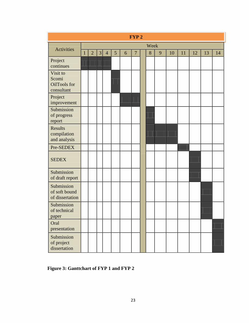
Figure 3: Ganttchart of FYP 1 and FYP 2
Activities Week
1 2 3 4 5 6 7
8 9 10 11 12 13 14
Project
continues
Visit to
Scomi
OilTools for
consultant
Project
improvement
Submission
of progress
report
Results
compilation
and analysis
Pre-SEDEX
SEDEX
Submission
of draft report
Submission
of soft bound
of dissertation
Submission
of technical
paper
Oral
presentation
Submission
of project
dissertation
FYP 2

24
CHAPTER 4
RESULT AND DISCUSSION
In this experiment, the performance of this synthetic HTHP fluid loss reducer was
observed by comparing mud properties in three different types of base oil which were
Sarapar 147, Saraline 185V, and Escaid 110. This synthetic HTHP fluid loss reducer is
Confi-Trol XHT that was supplied by SCOMI Oiltools. Confi-Trol F was used as the
base case study to compare with the performance of new Confi-Trol XHT. Using the
basic mud formulation 11.5lb/gal at 75/25 oil water ratio SBM formulation, the
formulation for each base oil were determined by using this ingredient:
Base oil Sarapar 145 / Saraline 185V / Escaid 110
Primary emulsifier Confi-Mul P
Secondary emulsifier Confi-Mul S
Viscosifier Confi-Gel
Fluid loss reducer Confi-Trol XHT / Confi-Trol F
Alkalinity source Lime
Brine Fresh water
CaCl
Weighting agent Drill Bar
Table 3: Elements in basic SBM formulation
Emulsifier, viscosifier, fluid loss reducer, and alkalinity source were made as
constant elements to generate 11.5lb/gal at 75/25 oil water ratio SBM formulation for
different type base oil. Quantities for these elements in mixing procedure for different
type of base oil were the same, and using some calculation, quantities of base oil, brine
and weighting agent can be determined.
PRODUCT DESCRIPTION QUANTITY
(gram)
CONFI-MUL P Primary emulsifier 3.00
CONFI-MUL S Secondary emulsifier 9.00
CONFI-GEL Viscosifier 8.50
CONFI-TROL XHT / CONFI-TROL F Fluid loss control 8.00
LIME Alkalinity source 8.00
Table 4: Constant elements in SBM formulation

25
Products Sarapar 147 Saraline 185V Escaid 110
Base oil 159.66 157.31 161.31
CONFI-MUL P 3.00 3.00 3.00
CONFI-MUL S 9.00 9.00 9.00
CONFI-GEL 8.50 8.50 8.50
CONFI-TROL XHT 8.00 8.00 8.00
LIME 8.00 8.00 8.00
Drillwater 67.37 67.23 67.47
CaCl 26.95 26.89 26.99
DRILL-BAR 192.71 195.26 190.92
Table 5: Formulation for Confi-Trol XHT for each base oil (value in gram)
Products Sarapar 147 Saraline 185V Escaid 110
Base oil 159.44 157.09 165.36
CONFI-MUL P 3.00 3.00 3.00
CONFI-MUL S 9.00 9.00 9.00
CONFI-GEL 8.50 8.50 8.50
CONFI-TROL F 8.00 8.00 8.00
LIME 8.00 8.00 8.00
Drillwater 67.28 67.13 67.63
CaCl 26.91 26.85 27.05
DRILL-BAR 193.06 195.61 186.65
Table 6: Formulation Confi-Trol F for each base oil (value in gram)
The mud rheology tests were conducted in two stages which were after the
mixing process at 120°F, so called initial results, and after the mud been introduced in
elevated high temperature and high pressure in hot rolling oven for some times, so
called after ageing results. It was decided to set the pressure of 500psi and the
temperature of 300°F for ageing process, for 16 hours to simulate for real applications of
HTHP wells.

26
4.1 RESULT
The results of evaluation the performance of synthetic HTHP fluid loss reducer
which was in this study was a Confi-Trol XHT in three different types of base oil which
were Sarapar 145, Saraline 185V, and Escaid 110, consists of two main subjects, initial
result right after mixing procedure, and after ageing result when the drilling mud
formulation were introduced into hot roller [see Appendix 2: figure 16] that the temperature have
been set to 300°F/149°C for 16 hours to simulate real well conditions.
4.1.1 Initial Properties:
Properties (Initial)
SPEC
Confi-Trol XHT Confi-Trol F
Sarapar 147
Saraline 185V
Escaid 110
Sarapar 147
Saraline 185V
Escaid 110
Mud density, lb/gal
11.5 11.5 11.5 11.5 11.5 11.5
Rheological properties
120 °F 120 °F 120 °F
120 °F 120 °F 120 °F
600 RPM 118 214 218 120 123 146
300 RPM 77 146 152 88 89 107
200 RPM 61 118 126 63 66 75
100 RPM 45 85 91 51 53 58
6 RPM >10@150 19 34 37 27 34 33
3 RPM 16 28 34 16 25 30
PV, cP 41 68 66 32 34 39
YP, lb/100 ft2 15-20@
120 36 78 86 56 55 68
Gel 10 sec, lb/100 ft2
26 30 35 31 34 35
Gel 10 min, lb/100 ft2
38 99 66 40 53 55
ES, volts at 120°F
> 400 819 1027 665 708 667 622
Table 7: Initial result after mixing procedure

27
4.1.2 After Ageing Properties:
AHR @ 150 C for 16h
SPEC
Confi-Trol XHT Confi-Trol F
Sarapar 147
Saraline 185V
Escaid 110
Sarapar 147
Saraline 185V
Escaid 110
Mud density, lb/gal
11.5 11.5 11.5 11.5 11.5 11.5
Rheological properties
120 °F 120 °F 120 °F
120 °F 120 °F 120 °F
600 RPM 84 180 220 137 150 193
300 RPM 59 108 136 95 105 127
200 RPM 46 77 112 53 78 85
100 RPM 24 51 72 35 51 55
6 RPM >10@15
0 18 32 10 20 36 37
3 RPM 15 15 6 14 21 13
PV, cP <30 25 72 84 42 45 66
YP, lb/100 ft2 15-25@
120 34 36 52 53 60 61
Gel 10 sec, lb/100 ft2
8-18 17 15 18 5 4 4
Gel 10 min, lb/100 ft2
15-30 22 21 31 14 6 6
HTHP, cc/30min at 300F
<4 4 4 5 9 10 14
ES, volts at 120°F > 400 952 641 481 410 385 354
Table 8: After ageing result

28
4.1.3 Result Analysis:
Using Confi-Trol XHT
Using Confi-Trol F
Plastic viscosity represents the
viscosity of a mud. It indicates
the amount of solid in the mud.
A low plastic viscosity
indicates that the mud is
capable of drilling rapidly and
high plastic viscosity is caused
by a viscous base fluid and by
excess colloidal solids. From
the results, it shows that
SARAPAR 145 have the
lowest plastic viscosity
compare to other base-oil.
Comparing the performance
between these two HTHP fluid
loss reducers, averagely,
CONFI-TROL F seems having
good plastic viscosity than
CONFI-TROL XHT.
Figure 4: Comparison of Plastic Viscosity

29
Figure 5: Comparison of Yield Point
Using Confi-Trol XHT
Using Confi-Trol F
Yield point indicates the ability
of mud to suspend and lift
cutting out from the annulus.
For HTHP conditions, yield
point specification to be reach
for mud to work best is in
range 15-35. It shows that
SARAPAR 145 with CONFI-
TROL XHT best suited for
HTHP wells in lifting the
cuttings while the others are
out of specification.

30
Figure 6: Comparison of Gel Strength for 10 seconds
Using Confi-Trol XHT
Using Confi-Trol F
The gel strength or shear
strength of a drilling mud
determines its ability to hold
solids in suspension and retain
its gel form. In this study,
barite was used as colloidal
clay. CONFI-GEL XHT also
being used as organophilic
hectorite clay, to give the gel
strength and also as viscosifier.
In this case, SARAPAR 145
with CONFI-TROL XHT
meets the specifications which
are for 10 seconds gel strength
, the range are 8-18 lb/100 ft²
and for 10 minutes gel strength,
the range are 15-30 lb/100 ft² .
It shows that CONFI-TROL F
could not withstand 300°F as
the differences between initial
reading and after hot roll were
too high.

31
Figure 7: Comparison of Gel Strength for 10 minutes
Using Confi-Trol XHT
Using Confi-Trol F
32
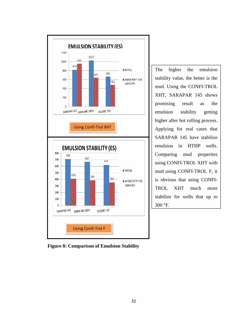
Figure 8: Comparison of Emulsion Stability
Using Confi-Trol XHT
Using Confi-Trol F
The higher the emulsion
stability value, the better is the
mud. Using the CONFI-TROL
XHT, SARAPAR 145 shows
promising result as the
emulsion stability getting
higher after hot rolling process.
Applying for real cases that
SARAPAR 145 have stabilize
emulsion in HTHP wells.
Comparing mud properties
using CONFI-TROL XHT with
mud using CONFI-TROL F, it
is obvious that using CONFI-
TROL XHT much more
stabilize for wells that up to
300 °F.

33
Figure 9: Comparison of HTHP Fluid Loss
Using Confi-Trol XHT
Using Confi-Trol F
HTHP fluid loss test is
designed to measure the mud
ability to prevent fluid loss
during the circulation in the
high temperature and high
pressure wells. Mud will
considered as good mud if
minimal fluid loss into the
formation. The results shows
that the less fluid loss were
SARAPAR 145 and
SARALINE 185V, both mixed
with CONFI-TROL XHT.
Meanwhile for CONFI-TROL
F, it seems the rate is
unacceptable for HTHP wells.

34
4.2 DISCUSSION
Confi-Trol XHT is a Scomi Oiltools‟ product that functioned as filtration and
suspension control in HTHP systems. It is a unique gel resin designed for use in oil and
synthetic based muds. The particle morphology, the resin solubility and the crosslink
density have been optimized for the fluid-loss additive can withstand in particular for
high temperature and high pressure applications. This study mainly to compare the
performance this product in the application of different base oil consists of Sarapar 145,
Saraline 185V, and Escaid 110.
Based on the result analyses that have been made, it shows that Sarapar 145 is the
most compatible base oil with Confi-Trol XHT. The formulation with Sarapar 145 gives
better result in term of PV, YP, Gel Strength, ES and HTHP Fluid Loss Test after ageing
process compare to the Saraline 185V, and Escaid 110. Performance after ageing
process indicates the ability of the formulation to withstand in HTHP well conditions
that have been set up to 300°F and 500psi in laboratory testing, simulated for the
standard HTHP well condition.
Sarapar 145 has the lowest rate of HTHP Fluid Loss, followed by Saraline 185V,
and Escaid 110, proves that Sarapar 145 formulation with Confi-Trol XHT gives greater
ability in fluid loss control. It means that even after being introduced on HTHP wells,
Sarapar 145 can reduces the fluid loss to the formation and slowing the mud cake
formation, increasing the chances for the drilling mud to circulate better in the wells
without having problems of immature mud cake formation in the wells that can cause
drilling pipe stuck or any problems regarding of this matter.
In any drilling mud formulation, mud rheology need meet requirement of industry
standard specification that being used by most company in oil and gas industry. Thus, in
accordance this specification, if mud formulation meets the range of these
specifications, it will be considered as good mud and ready to be used in real time
applications.

35
Table 9: Industry Standard Specification after Ageing Process
The result was taken by comparing with other fluid loss control that already had
been establish to evaluate its performance such as Confi-Trol, and Confi-Trol F. Confi-
Trol is a gilsonite act as a fluid loss control that been used in normal well conditions,
and Confi-Trol F is an liquid fluid loss for high temperature additive that mostly used
nowadays in HTHP wells. Using these two types of fluid loss control, the performance
measure to evaluate whether Confi-Trol XHT is better performance compare to the
existing one.
Rather than act alone in becoming the only HTHP additive, using HTHP
viscosifier can help improve its performance. Still it needs to be done pre well testing
whether it is compatible or not. The HTHP viscosifier that can be added in the
experimental list is a Confi-Gel HT, so the trend of the performance can be shown more
clearly and give enough information for drilling mud to choose in future.
In this research, the primary emulsifier that has been used was Confi-Mul P and
the secondary emulsifier was Confi-Mul S. Both were combinations to best suited in
HTHP conditions. Using secondary emulsifier is necessary in drilling mud to act as a
supplement, anionic emulsifier for base-oil fluids and also to enhance primary emulsifier
in paraffin carrier fluid.
Fluid Properties Specification
Mud density, SG 1.2
6 rpm dial reding 8-16
Yield point, lb/100ft2 15-35
10 sec gel strength, lb/100ft2 8-18
10 min gel strength, lb/100ft2 15-30
HTHP @ 300°F, 500 psi,
ml/30min <4
Electrical stability, volt >400
36
The improvement can be made by formulating new formulation of this SBM by
manipulating its concentration, thus, set a new value of its constant elements to achieve
industry specification. Confi-Trol XHT is used at low concentrations of 0.5 – 6 lb/bbl
(1.4 – 17.1 kg/m³), hence by using new formulation that generate mud at this range of
concentration, the result will be better than what were obtained from this research.
The emulsion stability also should be higher than what was obtained in this
research compromising by the factor of emulsion producing date. This emulsifier was
the old emulsifier, so it was not quite effective. In future, to get better results, this factor
need be considered.

37
CHAPTER 5
CONCLUSION
Nowadays, deep water wells have been explored due to its high production rate.
Unfortunately, the risks also will be higher rather than shallow water wells. In most
cases, drilling fluids that will be used in drilling extremely hot wells is oil based mud.
Today, we already have new invention on oil base drilling fluids to overcome
environment issue which is synthetic oil base. Eventually, there still no data regarding
the differences between this synthetic oil base which have various types of it. Form this
research, information on comparison based on the performance of the synthetic oil base
in term of rheology properties and behaviors in high temperature can help many
applications in HTHP wells to prevent problems occur. Also from this research, it can
lead the innovation of new formulating HTHP fluid loss reducer.
From the result obtained, it is shown that Confi-Trol XHT has better performance
than Confi-Trol F for HTHP wells application. In the elevated high temperature that
have been set up to 300°F and high pressure up to 500 psi, shown that Confi-Trol F
cannot withstand up to this conditions even though it is HTHP fluid loss reducer.
Improvements have been made to this new products and it was proven that it is a
successful products.
In conclusion, Confi-Trol XHT has better performance than Confi-Trol F in HTHP
conditions and is best suited using the Sarapar 145 as base-oil for better impact.

38
References
1. Andrew Teoq Ket Seang et al. “The comparison of saraline, sarapar, and diesel
performance as base oil at high temperature and high pressure.” SPE Paper.
2. Adam T. Bourgoyne Jr. et al. “Advanced Drilling Engineering.” SPE
Textbook Series
3. J.J. Azar and G. Robello Samuel. “Drilling Engineering.” PennWell Books,
2007
4. ASME Shale Shaker Committee. “Drilling Fluids Proccessing Handbook.”
Elsevier Inc. 2005
5. The University of Texas. “Principles of Drilling Fluid Control”. Twelfth
edition.
6. Dennis Denney, JPT Senior Technology Editor, “Technology Applications”.
7. Baker Hughes Drilling Fluid, “Drilling Fluids Reference Manual”.
8. Arvin D. Patel: “Oil-Based Drilling Fluid,” United States Patent, US
5888944, (30 March 1999)
9. M. Shahjahan Ali et al., “The Effect of High Temperature, High Pressure and
Aging on Water-Base Drilling Fluids”. King Fahd University of Petroleum
& Minerals, Dhahran, Saudi Arabia. (July 29, 1990)
10. Adelina J. Son et al., “Temperature-Stable Polymeric Fluid-Loss Reducer
Tolerant to High Electrolyte Contamination”. SPE Drilling Engineering.
(September 1987)
11. Jianghui Wu et al., “The Influence of Water-Base Mud Properties and
Petrophysical Parameter on Mudcake Growth, Filtrate Invasion, and
Formation Pressure”. Society of Petrophysicists and Well Log Analysts.
(February 2005)
12. H.A. Nasr-El-Din et al., “Filter-Cake Cleanup in MRC Wells Using
Enzyme/Surfactant Solutions”. SPE 98300, SPE Paper. (February 2006)
13. M.B. Al-Otaibi et al., “In-Situ Acid System to Clean Up Drill-in Fluid
Damage in High-Temperature Gas Wells”. IADC/SPE 103846, SPE Paper.
(November 2006)

39
14. AJ-Marhoun. M.A. and Rahman S.S., “Optimizing the Properties of Water-
Based Polymer Drilling Fluids for Penetrating Formations with Electrolyte
Influx”. Erdol Erdgas, (August 1988)
15. Viscometer specifications. Retrieved from
http://www.geodf.com/index.cfm/fuseaction/Pages.Page/id/306 ,
http://www.brookfieldengineering.com/education/applications/process-
exploration-drilling.asp ,
http://www.halliburton.com/ps/default.aspx?pageid=1566&navid=191&prodid=P
RN::JJN4K3CFQ
16. KMC OilTools Mud Testing Procedure. Retrieved from KMC OilTools.
17. Pliolite. Retrieved from
http://www.freepatentsonline.com/y2011/0183874.html ,
http://www.patentstorm.us/patents/7101829/description.html ,
http://www.weatherford.com/Products/Drilling/DrillingFluidsandDrillingWasteMa
nagement/OilandSyntheticBasedAdditives/index.htm

vi
APPENDICES
APPENDIX 1
Figure 10: Mixer
Figure 11: Baroid Mud Balance
Figure 12: Marsh Funnel Viscometer
Figure 13: FANN 35A Viscometer
iv
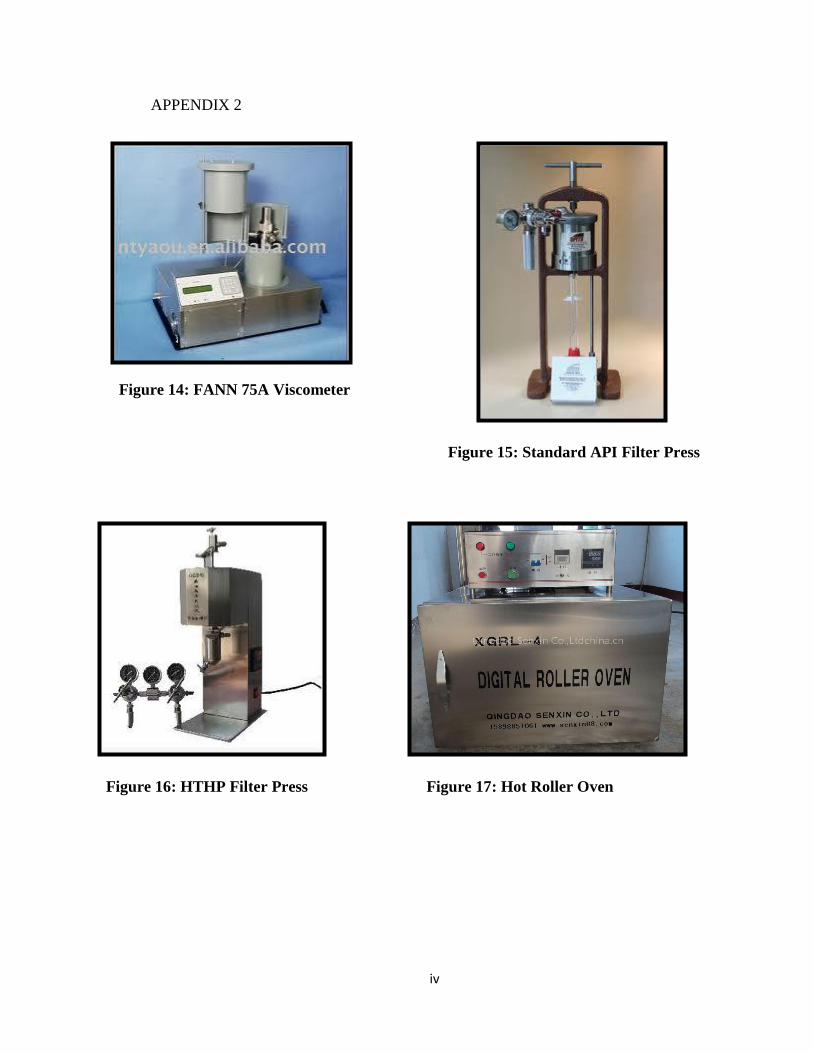
APPENDIX 2
Figure 14: FANN 75A Viscometer
Figure 15: Standard API Filter Press
Figure 16: HTHP Filter Press Figure 17: Hot Roller Oven

v
APPENDIX 3
Figure 18: Electric Stability kit