report 39/2007
TRANSCRIPT

Report 39/2007November 2007
Rail Accident Report
The derailment of a freight train at Washwood Heath8 September 2006

This investigation was carried out in accordance with:
l the Railway Safety Directive 2004/49/EC;l the Railways and Transport Safety Act 2003; and l the Railways (Accident Investigation and Reporting) Regulations 2005.
© Crown copyright 2007 You may re-use this document/publication (not including departmental or agency logos) free of charge in any format or medium. You must re-use it accurately and not in a misleading context. The material must be acknowledged as Crown copyright and you must give the title of the source publication. Where we have identified any third party copyright material you will need to obtain permission from the copyright holders concerned. This document/publication is also available at www.raib.gov.uk.
Any enquiries about this publication should be sent to:
RAIB Email: [email protected] Wharf Telephone: 01332 253300Stores Road Fax: 01332 253301 Derby UK Website: www.raib.gov.ukDE21 4BA
This report is published by the Rail Accident Investigation Branch, Department for Transport.

Rail Accident Investigation Branchwww.raib.gov.uk
3 Report 39/2007November 2007
Contents
Introduction 5
Summaryofthereport 6
Key facts about the accident 6
Immediate cause 6
Causal factors 7
Contributory factors 7
Underlying causes 7
Recommendations 7
TheDerailment 8
The parties involved 8
Location 8
The infrastructure 9
The train 9
Sequence of events 10
TheInvestigation 11
Sources of evidence 11
KeyFacts 12
Identification of the mechanism and point of derailment 12
Driving of the train 12
Track geometry 12
Track condition 12
The wagon fleet prior to 8 September 2006 13
Condition of wagon 609001 at the time of the derailment 16
Condition of the FAA wagon fleet following the derailment 20
The derailment of a freight train at Washwood Heath on 8 September 2006

Rail Accident Investigation Branchwww.raib.gov.uk
� Report 39/2007November 2007
Analysis 22
Identification of the immediate cause 22
Identification of casual and contributory factors 22
Identification of underlying causes 23
Conclusions 24
Immediate cause 24
Causal factors 24
Contributory factors 24
Underlying cause 24
ActionsalreadytakenbyEWSandNetworkRail 25
Recommendations 26
Recommendations to address causal and contributory factors 26
Recommendations to address underlying causes 26
Appendices 27
Appendix A: Glossary of abbreviations and acronyms 27
Appendix B: Glossary of terms 28

Rail Accident Investigation Branchwww.raib.gov.uk
� Report 39/2007November 2007
Introduction
1 The sole purpose of a Rail Accident Investigation Branch (RAIB) investigation is to prevent future accidents and incidents and improve railway safety.
2 The RAIB does not establish blame, liability or carry out prosecutions.3 Access was freely given by English Welsh and Scottish Railway (EWS) and Network Rail
to their staff, data and records in connection with the investigation. 4 Appendices at the rear of this report contain the following glossaries: l acronyms and abbreviations are explained in appendix A; and l technical terms (shown in italics the first time they appear in the report) are explained in
appendix B.5 All references to ‘left-hand’ and ‘right-hand’ are relative to the direction of travel of the
derailed train.

Rail Accident Investigation Branchwww.raib.gov.uk
� Report 39/2007November 2007
Summary of the report
Figure1:ExtractfromOrdnanceSurveymapshowingthelocationoftheaccident
Location of accident
© Crown Copyright. All rights reserved. Department for Transport 100020237 2007
Keyfactsabouttheaccident6 Train 4O26 was the 11:47 hrs service from Burton to Southampton Docks, operated by
EWS. It comprised locomotive 66070 hauling 17 flatbed wagons.7 At about 15:48 hrs on the 8 September 2006 the train departed from Washwood Heath Up
Side sidings. It left the yard along a reception siding from where it was routed onto the Down Goods via the series of four crossovers that link all tracks at the southwest end of Washwood Heath.
8 As the train passed over the crossover between the Down & Up Goods line and the Up Main line the leading bogie of the 13th wagon, 609001, derailed to the left-hand side. The general location of the derailment is shown in Figure 1.
Immediatecause9 The immediate cause of the derailment of wagon 609001 was the flange of the wheels on
the leading bogie climbing the gaugeface of the left-hand rail as they traversed a right-hand curve.
Rail Accident Investigation Branchwww.raib.gov.uk
7 Report 39/2007November 2007
Causalfactors10 The design and condition of the side bearer assembly on the FAA wagon produced high
levels of bogie rotational resistance and wheelunloading. A combination of the above factors gave rise to high lateral forces against the gaugecorner of the outer rail on curves and significant levels of wheel unloading when the wagon was subjected to track twist.
11 The actual behaviour of the bogie/side bearer assembly was not accurately predicted during the design scrutiny or during tests carried out in 2003 to validate a proposed modification of the underframe wear plates.
Contributoryfactors12 The tracktwist of 1 in 108 encountered by train 4O26 as it traversed the SY274 crossover.
Underlyingcause13 The process of design scrutiny did not correctly identify the factors that influence the
dynamic performance of the FAA wagon when exposed to track twist.
Recommendations14 The recommendations can be found in paragraph 97. They relate to the following areas: l EWS’s planned programme for replacing the existing side bearers with the UICsprung
bearers; l testing of a representative sample of the unmodified fleet to confirm that the existing
temporary maintenance procedure is effective; l a review of the design scrutiny process that was applied to certify the FAA wagon type
and its subsequent modifications; and l the need for design scrutiny to allow for the degradation of components in service
and the notification of railway undertakings of any consequential maintenance and/or inspection requirements.

Rail Accident Investigation Branchwww.raib.gov.uk
� Report 39/2007November 2007
The Derailment
Down Goods
Down Main
Up Main
Down & Up Goods
Spur
A
AB
B
Point of DerailmentDirection of Travel
Point SY273
Point SY274
Figure2:DiagramofSY274crossovershowingpointofderailment
Thepartiesinvolved15 Train 4O26 was operated by EWS. All of the wagons on the train were owned and
maintained by EWS.16 The track is owned and maintained by Network Rail.
Location17 The derailment occurred on a four track section of the mainline between Birmingham and
Derby near Washwood Heath No.1 signalframe.18 The derailment occurred within the trailingend of SY274A points (Figure 2). These are
located to the southwest of Washwood Heath Up Side sidings and form part of a crossover that connects the Down & Up Goods line with the Up Main (SY274 crossover). This crossover forms part of a series of crossovers linking all four running lines and the No.1 and 2 reception sidings.
19 This series of crossovers is located between 39 miles 44 chains and 39 miles 63 chains (from a datum at London Road Junction, Derby).

Rail Accident Investigation Branchwww.raib.gov.uk
9 Report 39/2007November 2007
Figure3:PhotographofFAAtypewagonwith9foot6inchcontainer
Theinfrastructure20 The track in the area of the derailment comprises 113 lb flat-bottomed rail fixed to wooden
sleepers or bearers with Pan baseplates and Pandrolclips. The crossover from the Down & Up Goods to the Up Main (formed by SY274A and B points) was installed in 1997.
21 The permissible speed for train movements over the crossovers is 15 mph (24.14 km/h). 22 Signalled moves to and from the sidings in this area are controlled from the Washwood
Heath No.1 signal frame, which is located adjacent to the crossovers described in paragraph 18. All other signalled routes in the area are controlled from Saltley Power Signal Box (PSB).
Thetrain23 Train 4O26 was the 11:47 hrs service from Burton to Southampton Docks. It comprised
locomotive 66070 hauling 17 flatbed wagons.24 The wagon that derailed was of the FAA type, designed to carry containers (Figure 3).
Thrall Europa built 100 of these wagons in 1998/9. The wagons’ tare weight is 33.5 tonnes, the distance between bogie centres is 15.39 m and they have a maximum permissible speed of 75 mph (120 km/h).
25 The low level of the wagon’s floor enables it to accommodate containers of up to 9 foot 6 inches (2896 mm) in height without infringement of the structure gauge.

Rail Accident Investigation Branchwww.raib.gov.uk
10 Report 39/2007November 2007
Sequenceofevents26 At about 12:15 hrs on 8 September 2006 train 4O26 arrived at Washwood Heath Up Side
sidings. The train composition remained unchanged whilst the train was in the sidings although the locomotive was detached in order to be fuelled then reattached for the onward journey.
27 At about 15:48 hrs the train departed from Washwood Heath Up Side sidings. It left the yard along a reception siding from where it was routed onto the Down Goods via the series of four crossovers that link all tracks at the southwest end of Washwood Heath.
28 As the train passed over the crossover between the Down & Up Goods line and the Up Main line the leading bogie of the 13th wagon derailed to the left-hand side.
29 The derailed bogie was dragged through SY724A, SY273B and SY273A points (see Figure 2) causing damage to each. At some position, shortly after passing over point SY273A, the derailed bogie rerailed and continued to run normally.
30 The signaller working in Washwood Heath No.1 signal frame heard and saw the derailed wagon and informed the signaller in Saltley PSB. The PSB signaller then stopped the train by setting another signal to danger.
31 Subsequent examination of the train revealed only limited damage to the derailed wagon and no evidence of any other wagon being involved.

Rail Accident Investigation Branchwww.raib.gov.uk
11 Report 39/2007November 2007
The Investigation
Sourcesofevidence32 In addition to the examinations and tests described in this report, the investigation obtained
evidence from: l theOnTrainDataRecorder (OTDR) data; and l documentation related to the design and acceptance processes for FAA type wagons.

Rail Accident Investigation Branchwww.raib.gov.uk
12 Report 39/2007November 2007
Key Facts
Identification of the mechanism and point of derailment33 The derailment mechanism was flange climbing. This was evidenced by distinct marks
on the gauge corner of the left-hand closurerail followed by marks on the top of the rail indicating that the two left-hand wheels on the leading bogie had run along the railhead before dropping off the field corner of the rail.
34 For a flange climb derailment to occur, there must be an increase in the ratio of lateral load to vertical load above a certain critical value, which is dependant on the friction and contact geometry between the wheel and the rail. Usually, this involves significant vertical wheel unloading (due to a track or vehicle fault or a combination of both) coinciding with lateral forces. If the amount of wheel unloading is high, even small lateral forces can cause the wheel to be forced upward to the extent that the flange tip can run onto the railhead. Flange climb is therefore often associated with the lateral forces generated as trains traverse curved track.
35 At the point of derailment the track was curving to the right in order to adopt the alignment of the Up Main. This curvature would have caused the left-hand wheels to engage with the gauge corner of the left-hand rail.
Drivingofthetrain36 The OTDR data shows that the speed of the train at the point of derailment was 14.9 mph
(23.98 km/h), below the 15 mph (24.14 km/h) permissible speed.37 There is no evidence that the train driver applied power or brake force in an abnormal
manner whilst traversing the crossovers.
Trackgeometry38 The geometry of track through the Down & Up Goods to Up Main crossover is: l a left-hand curve through SY724B points, then; l a rapid transition to a right-hand curve through SY274A points whilst crossing the right-
hand rail of the Up Main line to join; l the Up Main line which is laid to a left-hand curve with a high right-hand (outer) rail.39 A train routed from the Down & Up Goods line to the Up Main line encounters a sequence
of left-hand and right-hand curves whilst also experiencing adverse cant as it crosses onto the Up Main.
40 Given the above, a degree of track twist is inevitable.
Trackcondition41 Following the derailment a detailed track survey was carried out which allowed calculation
of the values of twist throughout the length of the SY274 crossover. These revealed significant levels of twist requiring corrective action according to Network Rail’s company standards. These are as shown in Table 1.

Rail Accident Investigation Branchwww.raib.gov.uk
13 Report 39/2007November 2007
Worstvaluesoftracktwist(closetopointofderailment)
Unloaded� Loaded2
Minimumactionstobetakenfollowingdetectionoftheselevelsoftracktwist
(Ref.NetworkRailCompanyStandardNR/SP/TRK/00�)
1 in 148 Correct within 14 days of discovery
1 in 108 Correct within 36 hours of discovery
Note: the difference between the loaded and unloaded values was due to voids between the bearers and the track ballast.
1 The level of static twist (i.e. no allowance for vertical track movement during the passage of a train) 2 The level of twist allowing for vertical movement of track due to the passage of a train
Table 1: Levels of twist measured by AEAT
42 Whilst these levels of track twist were sufficiently high for the standards to trigger a maintenance intervention they did not preclude the transit of trains or require the imposition of a speed restriction.
The wagon fleet prior to 8 September 2006 �2
43 The FAA wagon is fitted with two bogies. The weight of the wagon body is transferred to the bogies via a centre pivot assembly. This incorporates a concave centre casting located on top of the bogie into which is lowered a matching hemispherical centre pivot located on the underside of the wagon’s underframe. These two elements act as a ‘ball and socket’ joint, enabling weight to be transferred from wagon to bogie whilst enabling the bogie to rotate in relation to the wagon (Figure 4).
44 In common with most modern rolling stock FAA wagons are provided with side bearers. Side bearers are designed to take load as the wagon tilts when rounding a curve or in response to track twist.
45 When delivered to EWS in 1999 the FAA wagon’s side bearer assembly incorporated: l an inclined underframewearplate; and l a resilient side bearer block and roller (see also Figure 5).46 The purpose of the inclined underframe wear plate was to enable the carriage of containers
of up to 9 foot 6 inches (2896 mm) in height by tilting the wagon so that the top of the container remained within the loadinggauge.
47 In the period 1999 to 2003 there were three derailments involving FAA type wagons associated with track twist. This gave rise to the introduction of an increased frequency of Planned Preventative Maintenance (PPM) and the introduction of side bearer greasing.
48 EWS concluded that the propensity to derail was linked to the inclined underframe wear plates on the wagon. They reasoned that when these wagons traversed reverse curves these plates caused the two ends of the wagon to tilt in opposite directions (so generating a twist force). EWS considered that this twist force at the wagon ends, combined with the wagon’s structural stiffness, would be sufficient to cause one or more wheels to become unloaded so increasing the risk of derailment.
� The level of static twist (i.e. no allowance for vertical track movement during the passage of a train) 2 The level of twist allowing for vertical movement of track due to the passage of a train

Rail Accident Investigation Branchwww.raib.gov.uk
1� Report 39/2007November 2007
Figure 4: Schematic of centre pivot and side bearer arrangement
Figure 5: Diagram of the original side bearer assembly with inclined wear plate
49 EWS concluded that the increased derailment risk, and the consequent additional maintenance, was best addressed by removing the inclined underframe wear plates and replacing them with flat plates. Under this proposal the resilient side bearer blocks and rollers were to be retained in an unaltered condition (with the rollers acting as extreme bump stops).
(Inclined)
Roller

Rail Accident Investigation Branchwww.raib.gov.uk
1� Report 39/2007November 2007
50 The design scrutiny for the above alteration was undertaken by EWS’s engineering support group in its capacity as a Conformance Certification Body (CCB). This scrutiny was carried out in order to comply with the requirements of RailwayGroupStandard (RGS) GM/RT2001 ‘Design Scrutiny for Engineering Acceptance of Rail Vehicles’.
51 The CCB considered the impact of each of the following factors as part of their design scrutiny:
l lateralride; l verticalride; l bogie rotational resistance (X-factor�); and 4
l wheel unloading.52 For each of these factors the design scrutiny included an argument that the modified
design featuring flat underframe wear plates would improve on, or at least match, the performance of the original design. The evidence presented in support of these arguments is summarised in Table 2.
� The bogie X-factor is computed from the formula: X = Body / bogie yaw torque Wheelbase x axle load
� The highest of the original X-factor values obtained was 0.119, in excess of the 0.1 specified in Appendix B of RGS GM/RT2141. The acceptability of this value was therefore justified by reference to a computer simulation, in accordance with Appendix C of the same standard.
Factor Evidencepresentedindesignscrutiny
Lateral ride Vampire© computer simulation
Vertical ride Vampire© computer simulation
Bogie rotational resistance Further tests were carried out using test facilities owned by Bombardier Transportation UK Ltd. These tests were carried out on a FAA wagon with modified underframe wear plates and unlubricated side bearers. The test report indicated that the approved measure of bogie rotational resistance, the X-factor, was between 0.102 and 0.113.These X-factor values were less than the highest value of 0.119 obtained for the original design�.
Wheel unloading It was argued that the new side bearers were softer than the original ones and would allow more deflection before wheel unloading commenced.
Table 2: Evidence presented in design scrutiny to support contention that the modified design of FAA would improveon,oratleastmatch,theperformanceoftheoriginaldesign

Rail Accident Investigation Branchwww.raib.gov.uk
1� Report 39/2007November 2007
Figure 6: Diagram of the modified side bearer assembly with flat wear plate
53 The design scrutiny also contained an argument that the risk of gaugeinfringement by FAA wagons conveying 9 foot 6 inch (2896 mm) high containers could be managed without the need for inclined underframe wear plates. This argument was based on applying Network Rail’s accepted method of absolute gauging. This showed that the staticgauge of the FAA type wagon conveying a 9 foot 6 inch high container was compatible with Network Rail infrastructure.
54 Following the design scrutiny the inclined underframe wear plates were removed and replaced with flat plates. The modified assembly incorporated the following (see Figure 6):
l a flat underframe wear plate; and l a resilient side bearer block and roller.
55 EWS modified the FAA fleet during 2004. The modification of wagon 609001 was completed on 22 July 2004.
56 No further incidents were recorded involving FAA wagons until 8 September 2006 at Washwood Heath.
Condition of wagon 609001 at the time of derailment57 When AEA Technology Rail PLC (AEAT) and the RAIB examined vehicle 609001
they noted no obvious defects. The wagon had undergone its last annual inspection and safety tests during August 2006. However, given that there was no evidence of any other vehicles derailing, it was decided that wagon 609001 would be taken out of service in order that further testing could be conducted by AEAT.
(flat)
Roller

Rail Accident Investigation Branchwww.raib.gov.uk
17 Report 39/2007November 2007
Factor Criteria
(Ref RGS GM/RT2141)
Resultobtained CompliantwithRGSGM/RT2141
Bogie rotational resistance (X-factor)
X must not be greater than 0.1 (unless justified by computer simulation)
Leading bogie = 0.231
Trailing bogie = 0.314
No
Wheel unloading Max wheel unloading must not exceed 60 %�
79 % No
Table 3: Summary of results obtained during initial testing of wagon 609001
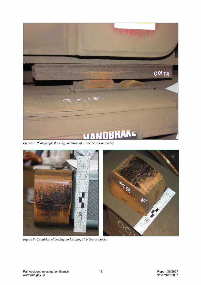
58 Some days later the vehicle was subjected to further visual examination at a Bombardier facility. During this further examination it was noted that the outer surfaces of the four steel underframe wear plates on both bogies were showing signs of corrosion, as shown in Figure 7.
59 On lifting the wagon body the side bearer blocks, for both the leading and trailing bogies, were showing signs of surface abrasion and lateral cracking/tearing. The condition of the leading and trailing side bearer blocks can be seen in Figure 8. The surfaces of the trailing bogie’s side bearer blocks showed indications of more abrasion and damage than those on the leading bogie.
60 The centre pivot concave bearing surfaces on both bogies were also examined. Both showed signs of wear with the trailing bearing having shaved off an appreciable amount of material (see Figure 9). The surfaces of the centre pins were scored but did not show signs of significant damage (see Figure 10).
61 In addition to the above, it was found that the side bearer blocks had been compressed by 4.5 mm which indicated that a significant proportion of the vehicle body weight had been carried by the four side bearer blocks.
62 Once the examination was complete AEAT in conjunction with EWS and RAIB subjected the wagon to tests to measure the bogies’ rotational resistance (X-factor) and the levels of wheel unloading. The results obtained are summarised in Table 3. 5
63 These results indicated likelihood that the high bogie rotational resistance and the propensity of the wheels to unload due to high torsionalstiffness were factors in the causation of the derailment on 8 September 2006. Further tests identified the extent to which the different components contributed to this performance. The results of these additional tests are summarised in Table 4.
� The off-loading of any wheel shall be such that for any axle the difference between the nominal wheel load (on level track) and the wheel load measured in the test does not exceed �0 % of the nominal wheel load.

Rail Accident Investigation Branchwww.raib.gov.uk
1� Report 39/2007November 2007
Configuration Result CommentFactor
Side bearer blocks
Centre pivot castingliner
Underframe wear plates
(worst value obtained)
Existing Existing X = 0.314 Wagon as delivered to test laboratory following derailment
Existing New X = 0.23
Removed Existing X = 0.058
Removed New X = 0.057
Bogierotationalresistance (X-factor)
New blocks (same design)
New X = 0.294
Wheelunloading
Existing Existing
Existing flat plates (as installed in 2003/4)
79 % unloading (worstaxle)
Wagon as delivered to test laboratory following derailment
Table 4: Summary of results obtained during testing of wagon 609001
64 These additional tests indicated that the fitment of new centre pivot casting liners, with either new or the existing side bearer blocks, would reduce the bogie rotational resistance but the values would still be well in excess of the value specified in RGS GM/RT2141.
65 The removal of the side bearer blocks significantly reduced the bogie rotational resistance to a value well within the RGS GM/RT2141 acceptance criteria. This suggests that a very significant proportion of the total weight of the wagon and load was being carried by the side bearer blocks/roller rather than the centre pivot.
66 One of the tests listed at Table 4 was carried out using similar conditions as the original tests that were carried out in May 2004 to validate the impact of the modification of the underframe wear plate. This new test gave an X-value of 0.294. This is significantly different from the previously obtained value of 0.113 (see Table 2). The difference is likely to have been brought about by a combination of:
l bedding down of the assembly after initial installation; l degradation of the side bearer block; and l corrosion or pitting on the steel wear plate.67 The tests showed that the design of the side bearer is an important factor contributing to
high levels of bogie rotational resistance and wheel unloading under track twist conditions.
Rail Accident Investigation Branchwww.raib.gov.uk
19 Report 39/2007November 2007
Figure 7: Photograph showing condition of a side bearer assembly
Figure 8: Condition of leading and trailing side bearer blocks

Rail Accident Investigation Branchwww.raib.gov.uk
20 Report 39/2007November 2007
Figure9:Conditionofleadingandtrailingcentrepivotsocketliners
Figure 10: Condition of the leading and trailing centre pivot pins
Condition of the FAA wagon fleet following the derailment68 Five randomly selected wagons from the FAA fleet (of 100 wagons) were also tested. The
average values obtained across this sample were as follows: Bogie rotational resistance (the original approved value was 0.119): l highest value obtained = 0.459 l lowest value obtained = 0.327 l mean value across sample = 0.38 Wheel unloading (the specified limit is 60 %): l highest value obtained = 89 % l lowest value obtained = 80 % l mean value across sample = 86 %69 The above values indicated a general problem across the fleet. As a result EWS introduced
a programme of periodic greasing of side bearers on all FAA wagons in order to limit the effects of high bogie rotational stiffness and excessive wheel unloading.

Rail Accident Investigation Branchwww.raib.gov.uk
21 Report 39/2007November 2007
Figure 11: UIC design of side bearer
70 On a sixth FAA wagon, 609052, the existing side bearer block/roller was replaced by a UIC sprung bearer (Figure 11). The values obtained for this modified configuration of side bearer was as follows:
l bogie rotational stiffness = 0.104 (the original approved value was 0.119) l average wheel unloading = 45 % (as compared to the specified limit of 60 %)

Rail Accident Investigation Branchwww.raib.gov.uk
22 Report 39/2007November 2007
Analysis
Identification of the immediate cause 71 The immediate cause of the derailment of wagon 609001 was the flange of the wheels on
the leading bogie climbing the gauge face of the left-hand rail as they traversed a right-hand curve (paragraphs 33 to 35).
Identification of causal and contributory factors 72 The survey conducted in the aftermath of the accident revealed 1 in 108 track twist close to
the point of derailment. According to Network Rail Company Standard NR/SP/TRK/001 this value of twist is acceptable for the transit of trains but the fault should be corrected within 36 hours of being found. The standard does not require the blocking of the line until the measured twist value is 1 in 90 or worse.
73 A 1 in 108 track twist fault is unusually high for any location on a running line but will sometimes be encountered by freight trains when operating in sidings.
74 The track twist encountered by train 4O26 as it traversed the SY274 crossover was a contributory factor in the derailment that followed. However, it cannot be considered as causal since at the time of the derailment it remained at an acceptable standard for the transit of trains. It should be noted that immediately before the derailment 12 wagons of train 4O26 passed over this section of track without derailing.
75 It is unlikely that Network Rail can significantly reduce the static twist on crossover SY274 given the limitations imposed by the track geometry in the area and the need to maintain sufficient cant for a linespeed of 90 mph (141 km/h) on the Up Main line. Nevertheless, the level of twist actually encountered by trains using the crossover can be improved by reducing the extent of voids under sleepers and bearers (see Table 16).
76 Tests carried out on wagon 609001 following the derailment revealed that the bogies had high rotational resistance. The tests also detected that wheels on the wagon became severely unloaded when the wagon was subject to twist, consistent with high torsional stiffness.
77 Tests carried out on five sample randomly selected wagons from the fleet showed similar results.
78 The performance measured in all of the above tests was non-compliant with the requirements of RGS GM/RT2141.
79 The design of the FAA wagon gave rise to poor dynamic performance when operating with unlubricated side bearers. High bogie rotational resistance would tend to force the wheel flange against the gauge corner of the rail (i.e. an increase of lateral force) whereas high torsional stiffness will give rise to wheel unloading when the wagon is exposed to twist (so reducing the vertical force). A combination of increased lateral force and decreased vertical force on the gauge corner of curved track will increase the propensity of the wagon to derail.
6 On 10 August 2007 another freight train derailment occurred on a crossover at Lawley Street, a short distance from Washwood Heath. Preliminary investigations by the RAIB indicate track twist to be a factor. As a consequence, issues associated with track maintenance in this area are subject to further investigation by the RAIB.

Rail Accident Investigation Branchwww.raib.gov.uk
23 Report 39/2007November 2007
80 The testing to date indicates that the non-compliant dynamic performance is associated with the design of the side bearer assembly. This side bearer block was carrying a very significant proportion of the total weight of the wagon (paragraph 61). This means that the load is being carried by the side bearer blocks rather than the centre pivot. This has given rise to high levels of friction, hence bogie rotational resistance, whilst also increasing the torsional stiffness of the wagon.
81 Each of the tests using new bearer blocks and a new centre pivot liner were done with the existing steel wear plate and the condition of this plate may also have contributed to the high bogie rotational resistance values that were measured.
82 Tests carried out on wagon 609052 showed that both bogie rotational stiffness and wheel unloading would be comparable with the original values measured with the approved design if the resilient block was replaced by a UIC standard sprung side bearer (see Figure 11).
83 The design and condition of the side bearer assembly was a causal factor in the derailment.84 Thrall Europa has now been taken over by Trinity Industries Inc. The new owner no
longer has an operation in the UK or Europe. The RAIB is unaware of any other wagons of a similar design. For this these reasons the RAIB does not intend to propose any recommendations for implementation by the manufacturer.
Identification of underlying causes85 The design of the FAA wagon had been subject to design scrutiny on two occasions.
The first was related to the initial acceptance in 1999. The scrutiny was then repeated in support of the modifications that took place in 2003-4.
86 In both cases the design scrutiny was carried out by EWS’s engineering support group in its capacity as a Conformance Certification Body. In neither case was the inherent problem with the design identified.
87 A test of bogie rotational resistance carried out in support of the 2003-4 modifications gave an X-factor value of 0.113. Bogie rotational resistance tests carried out in 2006 following the Washwood Heath derailment gave X-factor values that were two or three times higher. This discrepancy has not been fully explained, but for the test carried out in 2003 the side bearer components were in good condition (i.e. new side bearer blocks and underframe wear plates). It is possible that these have since deteriorated so reducing their dynamic performance. A worsening in the condition of the centre pivot lining and/or pin could also be a factor.
88 The process of design scrutiny and associated testing did not identify that the performance of the side bearer assembly would change (deteriorate) in service, nor did it identify that the levels of bogie rotational resistance would increase with wear. This arose due to a lack of understanding of the original design and the likely impact of the proposed modifications carried out during 2003-4. No detailed consideration was given to the likely impact of component wear. These shortcomings in the application of the process of design scrutiny are therefore an underlying cause of the derailment at Washwood Heath.

Rail Accident Investigation Branchwww.raib.gov.uk
2� Report 39/2007November 2007
Conclusions
Immediatecause89 The immediate cause of the derailment of wagon 609001 was the flange of the wheels on
the leading bogie climbing the gauge face of the left-hand rail as they traversed a right-hand curve (paragraph 71).
Causalfactors90 The design and condition of the side bearer assembly on the FAA wagon produced high
levels of bogie rotational resistance and wheel unloading. A combination of the above factors gave rise to high lateral forces against the gauge corner of the outer rail on curves and significant levels of wheel unloading when the wagon was subjected to track twist (paragraph 79 and Recommendations 1 and 2).
91 The actual behaviour of the bogie/side bearer assembly was not accurately predicted during the design scrutiny or during tests carried out in 2003 to validate the proposed modification of the underframe wear plates (paragraph 88 and Recommendation3).
Contributoryfactors92 The track twist of 1 in 108 encountered by train 4O26 as it traversed the SY274 crossover
(paragraphs 72 to 75).
Underlyingcause93 The process of design scrutiny did not correctly identify the factors that influence the
dynamic performance of the FAA wagon when exposed to track twist (paragraph 88 and Recommendations 3 & 4).
Rail Accident Investigation Branchwww.raib.gov.uk
2� Report 39/2007November 2007
Actions already taken by EWS and Network Rail
94 Following the programme of testing after the derailment at Washwood Heath EWS immediately implemented an enhanced regime of PPM. This included the periodic application of grease on the side bearer assembly to reduce the coefficient of friction at this interface. EWS have agreed to undertake testing of wagons with lubricated side bearers that are approaching the end of their first PPM period to ensure that the lubrication procedures in place maintain acceptable bogie rotational resistance values throughout the PPM period.
95 In addition to the above EWS are undertaking a programme to remove resilient block side bearers and replace them with a UIC standard sprung side bearer (see also paragraph 70).
96 Network Rail has undertaken remedial works to reduce the twist encountered by trains traversing SY274 crossover at Washwood Heath so far as is possible given the track geometry constraints. It has also introduced a programme of enhanced track monitoring in order to detect any emerging problems associated with track twist under load.

Rail Accident Investigation Branchwww.raib.gov.uk
2� Report 39/2007November 2007
Recommendations
97 The following safety recommendations are made6: 7
Recommendationstoaddresscausalandcontributoryfactors
1 EWS should complete its programme for installing UIC sprung side bearers in FAA wagons in order to overcome the known deficiencies with the existing arrangement (paragraph 90).
2 EWS, pending the replacement of all existing side bearers, should test a representative sample of the unmodified fleet of FAA wagons in order to confirm that the values obtained for bogie rotational resistance and torsional stiffness remain acceptable once the central pivot and side bearer components have been subject to wear and to measure any change in the performance of the side bearer lubrication between PPM (paragraphs 90 and 91).
Recommendationstoaddressunderlyingcauses
3 Engineering Support Group Ltd. (formerly part of EWS - engineering service group), in its capacity as a Conformance Certification Body, should review the design scrutiny process that was applied to certify the FAA wagon type and its subsequent modifications. The review should identify any weakness in the management systems that resulted in the non-identification of the design defects associated with the side bearer assembly. The review should also consider the checks that are carried out to confirm the validity of testing done in support of the design. ESG Ltd. should implement any changes to its processes found necessary following this review (paragraph 93).
4 Engineering Support Group Ltd. should implement changes to its processes to mandate that when undertaking scrutiny of design and proposed maintenance the degradation of components in service is taken into account and the railway undertaking is advised of any additional maintenance and/or inspection requirements to keep the vehicle in a safe state as components wear (paragraph 93).
� Responsibilities in respect of these recommendations are set out in the Railways (Accident Investigation and Reporting) Regulations 200� and the accompanying guidance notes, which can be found on RAIB’s web site at www.raib.gov.uk

Rail Accident Investigation Branchwww.raib.gov.uk
27 Report 39/2007November 2007
Appendices
Glossaryofabbreviationsandacronyms AppendixAAEAT AEA Technology Rail Plc.
ESG Engineering Support Group
EWS English Welsh and Scottish Railways
OTDR On Train Data Recorder
PSB Power Signal Box
PPM Planned Preventative Maintenance
UIC Union Internationale des Chemin de Fer
CCB Conformance Certification Body

Rail Accident Investigation Branchwww.raib.gov.uk
2� Report 39/2007November 2007
Glossaryofterms AppendixBAll definitions marked with an asterisk, thus (*), have been taken from Ellis’ British Railway Engineering Encyclopaedia © Iain Ellis. www.iainellis.com
Absolute gauging The full assessment of clearances between a rail vehicle and the Infrastructure on a section of track, and between the vehicle and other vehicles on adjacent tracks.*
Bearers A term used to describe a wooden or concrete beam used to support the track.*
Bogie A metal frame equipped with two or three wheelsets and able to rotate freely in plan, used in pairs under rail vehicles to improve ride quality and better distribute forces to the track.*
Bogie rotational The force required to rotate a bogie in plan when loaded.resistance
Cant The design amount by which one rail of a track is raised above the other rail, measured over the rail centres.*
Chain A unit of length, being 66 feet or 22 Yards (approximately 20117 mm). There are 80 Chains in one standard mile.*
Closure rail A short length of running rail used to complete a track assembly, particularly between two switch and crossing units (S&C Units).*
Coefficient of friction The ratio of the force causing a body to slide along a plane (in the direction of sliding) to the normal force pressing the two surfaces together.
Conformance A Conformance Certification Body is an organisation authorised to Certification Body issue Certificates of Conformance to verify that rail vehicles conform to the relevant mandatory requirements of relevant railway standards.
Crossover Two turnouts (TO) or single leads connected to permit movements between parallel tracks. Crossovers thus may be facing or trailing.*
Down (line) A track on which the normal passage of trains is in the down direction (in this instance ‘down’ is towards Birmingham).*
Field corner Corner of the rail head that faces away from the four foot.
Flange climb(ing) A fault condition in which the lateral force exerted by a rail wheel is sufficient to force the wheel up the running face of the rail. Once the flange tip clears the rail head a derailment normally occurs.*
Flatbed (wagons) These are wagons designed to carry long or bulky items of freight, e.g. containers
Gauge corner The curved profile of the rail head between running surface and running edge.*
Gauge infringement The presence of a structure or another rail vehicle within the vehicle gauge.*

Rail Accident Investigation Branchwww.raib.gov.uk
29 Report 39/2007November 2007
Gauge face The side of the rail head facing towards the opposite running rail, e.g. the face to which the track gauge is measured.*
Lateral ride The amount of horizontal or lateral movement that a structure or person would be subjected to during a journey.
Liner (of centre The replaceable material that forms the load bearing face within a pivot casting) bogie centre pivot
Loading gauge The set of dimensions that a load on a rail vehicle must be within in order to run in normal traffic. Any load that cannot be got to fit is classed as out of gauge.*
On Train Data An electronic device wired into a train’s electrical systems for the purpose of Recorder recording with respect to time key control and system conditions
Pan baseplate A baseplate intended to be fitted with Pandrol Clips.*
Pandrol clip (Trade name) A rail clip for flat bottom rail manufactured by the Pandrol company.
Railway Group A document mandating the technical or operating standards required Standard of a particular system, process or procedure to ensure that it interfaces correctly with other systems, process and procedures. Network Rail (NR) produces Network Rail Company Standards (NRCS) that detail how the requirements of the Railway Group Standards are to be achieved on its system.*
Side bearer A component located on the side frame of a bogie (one per side) which provides vertical support to the vehicle body whilst allowing the bogie to rotate. (On some bogie designs the vertical support provided is only significant when the vehicle body rolls).
Side bearer block The support material that is located on the side frame of a FAA type bogie and which supports the weight of the wagon body.
Signal frame A cast iron frame carrying the levers for the operation of points and signals.
Static gauge/gauging A method of producing an approximate Kinematic Envelope (KE) by adding an allowance to the Static Envelope in defined areas. This means that a vehicle with the appropriate Static Envelope should be Clear on any Route designed to accommodate the appropriate approximate Kinematic Envelope, as the allowances do not depend on the characteristics of the vehicle itself. This method errs very much on the side of caution, and it has been superseded by Kinematic Gauging in the drive for ever larger Vehicle Gauges.*
Torsional stiffness Applied to a rail vehicle, the resistance the vehicle structure has to twisting along its length.*
Track twist A rapid change in cant or cross level.*
Trailing end Aligned in a direction towards the direction to which trains normally (of points) depart.*
Rail Accident Investigation Branchwww.raib.gov.uk
30 Report 39/2007November 2007
Underframe wear The flat sheet of steel located on the FAA wagon underframe above the plate side bearing block that acts as a rubbing surface
Up (line) A track on which the normal direction of trains is in the up direction (in this instance ‘up’ is towards Derby).*
UIC Union Internationale des Chemins de Fer, an international organisation formed in 1922 comprising a union of various railway companies and administrations. It agrees common standards and practices.*
UIC sprung bearer Standard sprung vehicle side bearer that relies on steel springs for supporting the vehicle body on the bogie side frame
Vampire (Trade name) Vehicle Dynamic Modelling Package in a Railway Environment. A dynamic modelling system for Rail Vehicles which allows a virtual model of any Rail Vehicle to be run over real measured Track Geometry. Produced by AEA Technology.*
Vertical ride The amount of vertical movement that a structure or person would be subjected to during a journey
Wheel unloading Describing the worst case effect of cant deficiency, load distribution, suspension travel, tortional stiffness and twist, which can be the reduction of the force applied by one or more Rail Wheels to very low or even small negative values. This can lead to derailments, see flange climb.*
X-factor The numerical value derived from a function of the body/yaw torque, wheelbase and axle loads. These values are determined by testing and measurement. Under normal circumstances the X-factor must not exceed a value of 0.1

This report is published by the Rail Accident Investigation Branch, Department for Transport.
© Crown copyright 2007
Any enquiries about this publication should be sent to:
RAIB Telephone: 01332 2�3300The Wharf Fax: 01332 2�3301Stores Road Email: [email protected] UK Website: www.raib.gov.ukDE21 �BA