report configuration
TRANSCRIPT
8/3/2019 Report Configuration
http://slidepdf.com/reader/full/report-configuration 1/21
Clockwork A/S Product Modelling
42451 Mass Customization - Application of Product Configuration
23-09-2011
8/3/2019 Report Configuration
http://slidepdf.com/reader/full/report-configuration 2/21
1
Table of ContentsIntroduction ................................................................................................................................................. 2
Problem Definition ....................................................................................................................................... 2
Development of Specification Processes ...................................................................................................... 3
Step 1: Identifying and characterizing the most important specification processes .................... .............. . 3
Step 2: Analysis of requirements for the specification processes .............................................................. 6
Step 3: Designing the future specification process .................................................................................... 7
Scenario 1 ............................................................................................................................................ 7
Scenario 2 ............................................................................................................................................ 8
Scenario 3 ............................................................................................................................................ 9
Step 4: Evaluation and choice of solution ............................................................................................... 10
Step 5: Plan of action and organization of further work .......................................................................... 12
Product analysis ......................................................................................................................................... 13
Product Variant Master .......................................................................................................................... 13
Productions sequence ............................................................................................................................ 16
Object Oriented Analysis ............................................................................................................................ 17
Class diagram ......................................................................................................................................... 17
CRC card................................................................................................................................................. 18
Object Oriented Design .............................................................................................................................. 19
8/3/2019 Report Configuration
http://slidepdf.com/reader/full/report-configuration 3/21
2
IntroductionThe world today forces both big and small companies to think about optimization, reducing prices well still
maintaining a level of customization to accommodate potential customers. There are so many companies
today and thereby a lot of competition especially with the East, growing like it does, to threatening the life
of a company. Companies are therefore forced to think in new ways and ease their workflow and workprocesses in order to reduce time, and thereby money, to e.g. make an offer to a customer. A way to do
this, which is more and more used, is by creating a configuration system to maintain the standardized and
trivial work.
A configuration system is a way to ease the creation of e.g. an offer, by selecting different component by
different rules and possibilities. By using such a configuration system a company can retrieve and keep the
competitive edge since they are now faster and cheaper since both time and money are saved.
Problem DefinitionThis project will deal with a small clock company called Clockwork A/S with about 50 employees producing
and selling clock in the European market. The company is selling around 21000 clocks a year divided
between four different product families. The company has four main departments connected to the sales
and engineering tasks: Sales, Design, Production preparation and Logistics. The company has various
communication problems between these departments. In addition a lot of time is spent on unnecessary
paper work, paper work often contains errors and throughput time is fairly high. An extern consultant has
recommended that Clockwork A/S work in a more process-oriented manner to reduce these problems. She
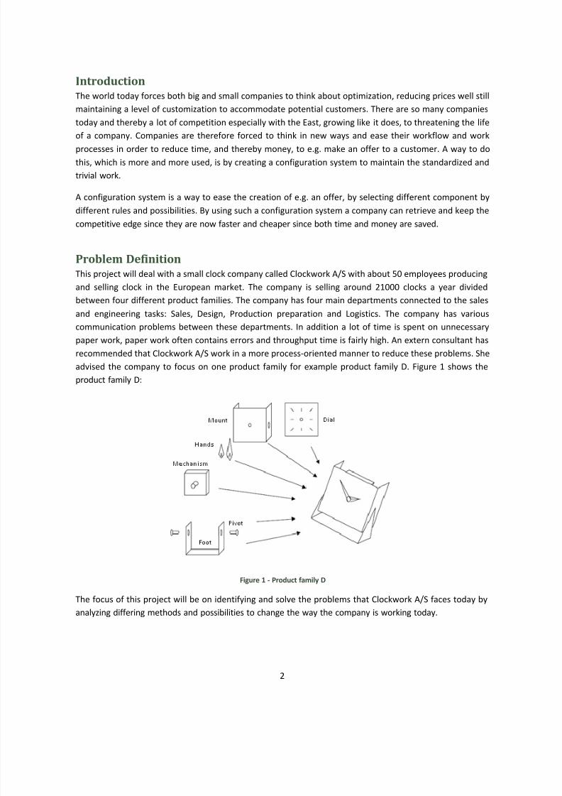
advised the company to focus on one product family for example product family D. Figure 1 shows the
product family D:
Figure 1 - Product family D
The focus of this project will be on identifying and solve the problems that Clockwork A/S faces today by
analyzing differing methods and possibilities to change the way the company is working today.
8/3/2019 Report Configuration
http://slidepdf.com/reader/full/report-configuration 4/21
3
The goal of this project is to help Clockwork A/S to standardize about 80% of the product family D and it is
these 80% that will be in focus. By standardizing product family D the company hopes to reduce the time
spend on specifying an order.
Development of Specification ProcessesIn order to fully understand and investigate the Clockwork A/S specification process and hereafter give
suggestions to identify the problems and room for improvement systematically, different steps will be
followed in order to investigate possible changes in the specification process to be more a systematic
approach. The different steps to analyze and investigate this will be:
1. Identifying and characterizing the most important specification processes
2. Analysis of requirements for the specification processes
3. Designing the future specification process
4. Evaluation and choice of solution
5. Plan of action and organization of further work
Step 1: Identifying and characterizing the most important specification
processes
The first step when developing a new specification process is to analyze the current processes and
specifications. Improvements cannot be made unless there is a clear understanding of what the current
situation is.
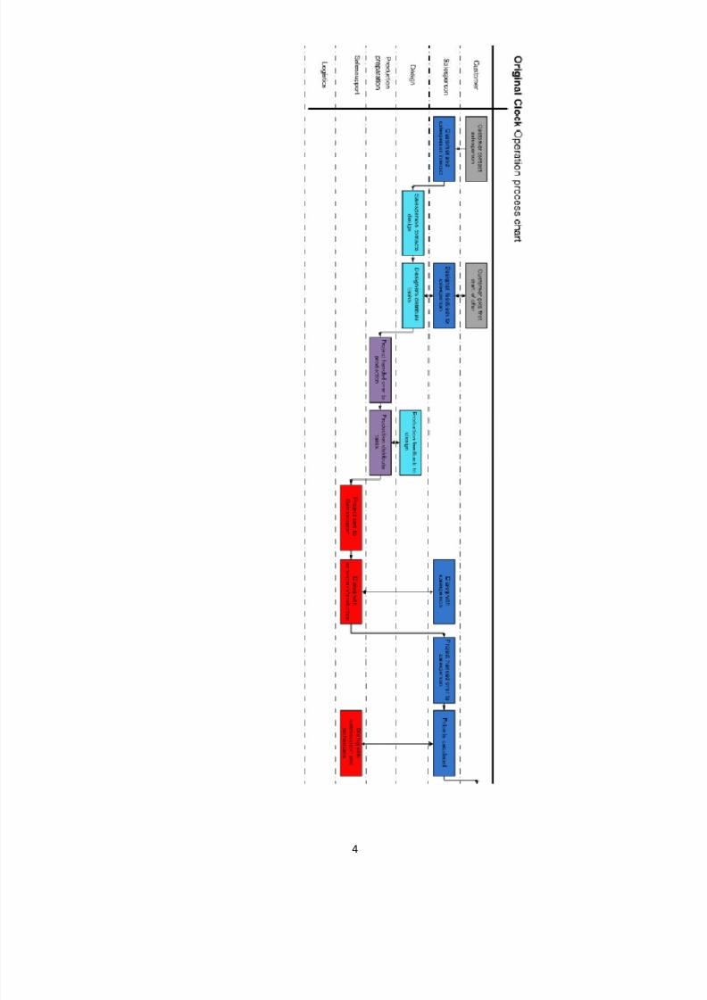
The current specification processes related to the production of offers have been analyzed and depicted in
a flow diagram. Figure 2 show the sequence of events from the first time a customer inquires about a clockuntil production of the order begins. A flow diagram like the swimming lane diagram shown in figure 2 gives
a clear pitcher of who is involved in the processes, in what order they take place as well as highlighting if
any time is wasted in avoidable interaction. This kind of diagram can be a good first tool to recognizing
what processes can be changed or eliminated to save both time and money. As value-adding and non-value
adding activities can often be clearly identified with a flow diagram.
Figure 2 shows that many different people and departments are involved in Clockwork´s A/S processes of
taking orders and getting specifications ready before production ever starts. This means that responsibility
of the order changes hands frequently which increase the likelihood of mistakes being made. In general it is
presumed, when the amount of people handling an order increases the likelihood of errors increases.
Errors need to be limited as much as possible as they increase costs.
8/3/2019 Report Configuration
http://slidepdf.com/reader/full/report-configuration 5/21
4
8/3/2019 Report Configuration
http://slidepdf.com/reader/full/report-configuration 6/21
5
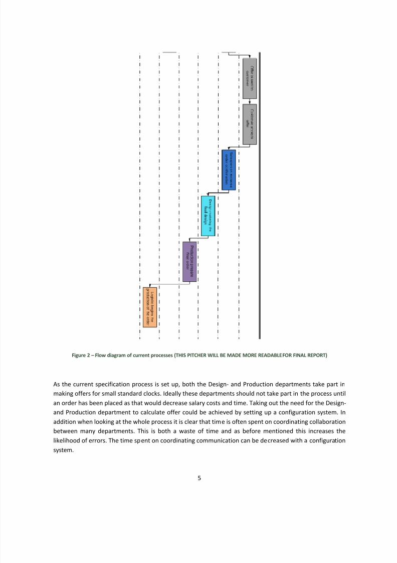
Figure 2 Flow diagram of current processes (THIS PITCHER WILL BE MADE MORE READABLEFOR FINAL REPORT)
As the current specification process is set up, both the Design- and Production departments take part in
making offers for small standard clocks. Ideally these departments should not take part in the process untilan order has been placed as that would decrease salary costs and time. Taking out the need for the Design-
and Production department to calculate offer could be achieved by setting up a configuration system. In
addition when looking at the whole process it is clear that time is often spent on coordinating collaboration
between many departments. This is both a waste of time and as before mentioned this increases the
likelihood of errors. The time spent on coordinating communication can be decreased with a configuration
system.
8/3/2019 Report Configuration
http://slidepdf.com/reader/full/report-configuration 7/21
6
Step 2: Analysis of requirements for the specification processes
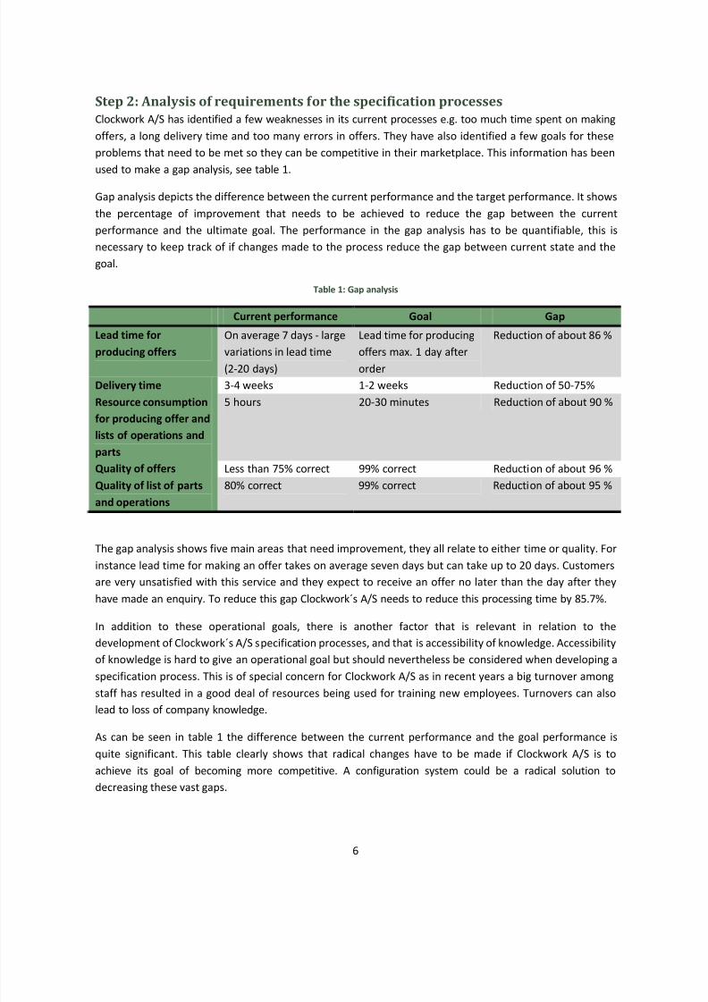
Clockwork A/S has identified a few weaknesses in its current processes e.g. too much time spent on making
offers, a long delivery time and too many errors in offers. They have also identified a few goals for these
problems that need to be met so they can be competitive in their marketplace. This information has been
used to make a gap analysis, see table 1.
Gap analysis depicts the difference between the current performance and the target performance. It shows
the percentage of improvement that needs to be achieved to reduce the gap between the current
performance and the ultimate goal. The performance in the gap analysis has to be quantifiable, this is
necessary to keep track of if changes made to the process reduce the gap between current state and the
goal.
Table 1: Gap analysis
Current performance Goal Gap
Lead time for
producing offers
On average 7 days - large
variations in lead time(2-20 days)
Lead time for producing
offers max. 1 day afterorder
Reduction of about 86 %
Delivery time 3-4 weeks 1-2 weeks Reduction of 50-75%
Resource consumption
for producing offer and
lists of operations and
parts
5 hours 20-30 minutes Reduction of about 90 %
Quality of offers Less than 75% correct 99% correct Reduction of about 96 %
Quality of list of parts
and operations
80% correct 99% correct Reduction of about 95 %
The gap analysis shows five main areas that need improvement, they all relate to either time or quality. For
instance lead time for making an offer takes on average seven days but can take up to 20 days. Customers
are very unsatisfied with this service and they expect to receive an offer no later than the day after they
have made an enquiry. To reduce this gap Clockwork´s A/S needs to reduce this processing time by 85.7%.
In addition to these operational goals, there is another factor that is relevant in relation to the
development of Clockwork´s A/S specification processes, and that is accessibility of knowledge. Accessibility
of knowledge is hard to give an operational goal but should nevertheless be considered when developing a
specification process. This is of special concern for Clockwork A/S as in recent years a big turnover among
staff has resulted in a good deal of resources being used for training new employees. Turnovers can also
lead to loss of company knowledge.
As can be seen in table 1 the difference between the current performance and the goal performance is
quite significant. This table clearly shows that radical changes have to be made if Clockwork A/S is to
achieve its goal of becoming more competitive. A configuration system could be a radical solution to
decreasing these vast gaps.
8/3/2019 Report Configuration
http://slidepdf.com/reader/full/report-configuration 8/21
7
Step 3: Designing the future specification process
The future specification process for Clockwork A/S has to meet the demands of step 2 as well as consider
the problems that arose when examining the flow diagram in step 1. There are many different ways to
improve the specification processes that meet some or all of the requirements of step 1 and 2. To sort out
the best solution for the specification processes three scenarios were made with aim of picking the most
efficient and profitable solution. Here below are the three scenarios as well as a flow diagram of each
scenario.
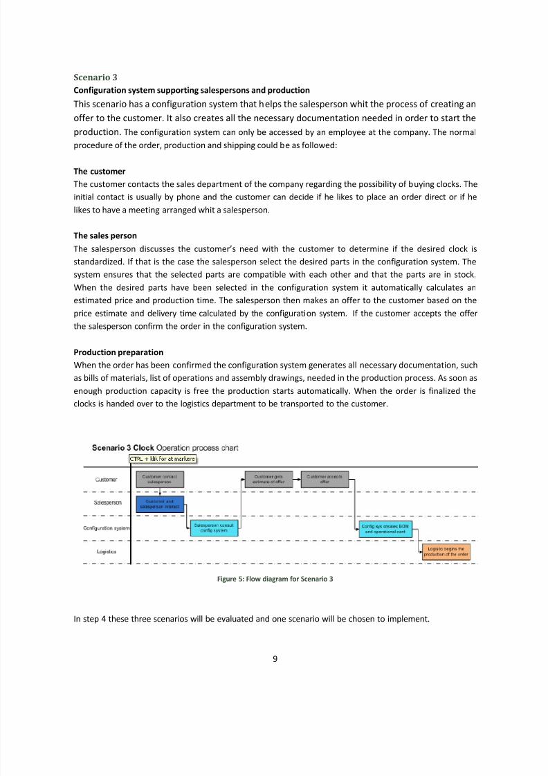
Scenario 1
Salesperson with configuration system
This scenario has a configuration system to help the salesperson to give the correct information about the
products that the company have. The configuration system is on the salespersons computer and can
therefore only be accessed by a salesperson from the company. The configuration system is like a catalogue
on the computer. The normal procedure of the order, production and shipping could be as followed:
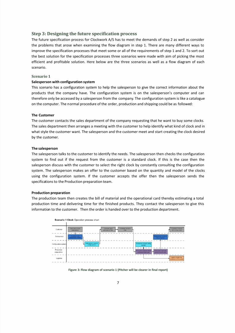
The CustomerThe customer contacts the sales department of the company requesting that he want to buy some clocks.
The sales department then arranges a meeting with the customer to help identify what kind of clock and in
what style the customer want. The salesperson and the customer meet and start creating the clock desired
by the customer.
The salesperson
The salesperson talks to the customer to identify the needs. The salesperson then checks the configuration
system to find out if the request from the customer is a standard clock. If this is the case then the
salesperson discuss with the customer to select the right clock by constantly consulting the configuration
system. The salesperson makes an offer to the customer based on the quantity and model of the clocks
using the configuration system. If the customer accepts the offer then the salesperson sends the
specifications to the Production preparation team.
Production preparation
The production team then creates the bill of material and the operational card thereby estimating a total
production time and delivering time for the finished products. They contact the salesperson to give this
information to the customer. Then the order is handed over to the production department.
Figure 3: Flow diagram of scenario 1 (Pitcher will be clearer in final report)
8/3/2019 Report Configuration
http://slidepdf.com/reader/full/report-configuration 9/21
8
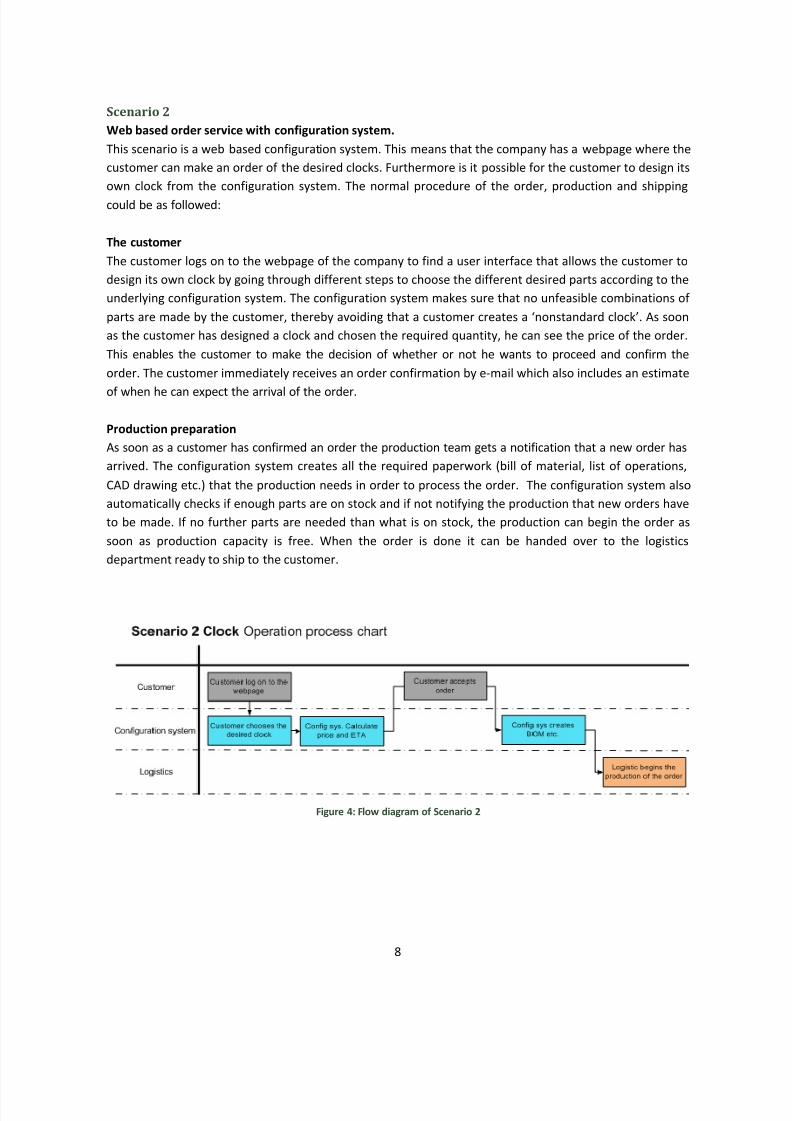
Scenario 2
Web based order service with configuration system.
This scenario is a web based configuration system. This means that the company has a webpage where the
customer can make an order of the desired clocks. Furthermore is it possible for the customer to design its
own clock from the configuration system. The normal procedure of the order, production and shipping
could be as followed:
The customer
The customer logs on to the webpage of the company to find a user interface that allows the customer to
design its own clock by going through different steps to choose the different desired parts according to the
underlying configuration system. The configuration system makes sure that no unfeasible combinations of
parts are made by the customer, thereby avoiding that a customer creates a nonstandard clock. As soon
as the customer has designed a clock and chosen the required quantity, he can see the price of the order.
This enables the customer to make the decision of whether or not he wants to proceed and confirm the
order. The customer immediately receives an order confirmation by e-mail which also includes an estimate
of when he can expect the arrival of the order.
Production preparation
As soon as a customer has confirmed an order the production team gets a notification that a new order has
arrived. The configuration system creates all the required paperwork (bill of material, list of operations,
CAD drawing etc.) that the production needs in order to process the order. The configuration system also
automatically checks if enough parts are on stock and if not notifying the production that new orders have
to be made. If no further parts are needed than what is on stock, the production can begin the order as
soon as production capacity is free. When the order is done it can be handed over to the logistics
department ready to ship to the customer.
Figure 4: Flow diagram of Scenario 2
8/3/2019 Report Configuration
http://slidepdf.com/reader/full/report-configuration 10/21
8/3/2019 Report Configuration
http://slidepdf.com/reader/full/report-configuration 11/21
10
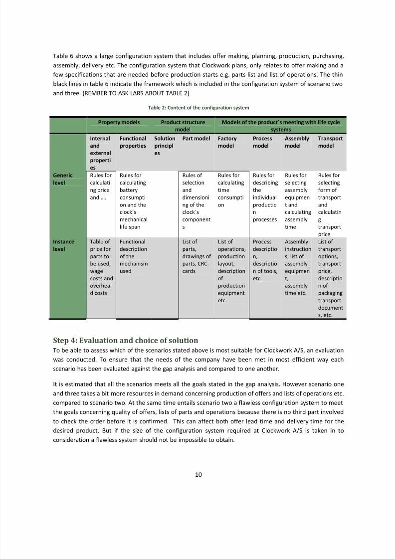
Table 6 shows a large configuration system that includes offer making, planning, production, purchasing,
assembly, delivery etc. The configuration system that Clockwork plans, only relates to offer making and a
few specifications that are needed before production starts e.g. parts list and list of operations. The thin
black lines in table 6 indicate the framework which is included in the configuration system of scenario two
and three. (REMBER TO ASK LARS ABOUT TABLE 2)
Table 2: Content of the configuration system
Property models Product structure
model
Models of the product´s meeting with li fe cycle
systems
Internal
and
external
properti
es
Functional
properties
Solution
principl
es
Part model Factory
model
Process
model
Assembly
model
Transport
model
Generic
level
Rules for
calculati
ng price
and .
Rules for
calculating
battery
consumption and the
clock´s
mechanical
life span
Rules of
selection
and
dimensioning of the
clock´s
component
s
Rules for
calculating
time
consumption
Rules for
describing
the
individualproductio
n
processes
Rules for
selecting
assembly
equipment and
calculating
assembly
time
Rules for
selecting
form of
transportand
calculatin
g
transport
price
Instance
level
Table of
price for
parts to
be used,
wage
costs and
overhea
d costs
Functional
description
of the
mechanism
used
List of
parts,
drawings of
parts, CRC-
cards
List of
operations,
production
layout,
description
of
production
equipmentetc.
Process
descriptio
n,
descriptio
n of tools,
etc.
Assembly
instruction
s, list of
assembly
equipmen
t,
assembly
time etc.
List of
transport
options,
transport
price,
descriptio
n of
packagingtransport
document
s, etc.
Step 4: Evaluation and choice of solution
To be able to assess which of the scenarios stated above is most suitable for Clockwork A/S, an evaluation
was conducted. To ensure that the needs of the company have been met in most efficient way each
scenario has been evaluated against the gap analysis and compared to one another.
It is estimated that all the scenarios meets all the goals stated in the gap analysis. However scenario one
and three takes a bit more resources in demand concerning production of offers and lists of operations etc.
compared to scenario two. At the same time entails scenario two a flawless configuration system to meet
the goals concerning quality of offers, lists of parts and operations because there is no third part involved
to check the order before it is confirmed. This can affect both offer lead time and delivery time for the
desired product. But if the size of the configuration system required at Clockwork A/S is taken in to
consideration a flawless system should not be impossible to obtain.
8/3/2019 Report Configuration
http://slidepdf.com/reader/full/report-configuration 12/21
11
Scenario one is an improvement of the old process if you look at the number of steps in the process. This
will decrease the time for producing offers as well as delivery time for the product. At the same time both
the salesperson and production team has a chance to check the order for errors before the productions
starts, this will ensure a low error rate and high quality of both offers and productions plans. Even though
this is an improvement from the old system the salesperson and production team will have to spend a lot of
time using the system and communicate with one another, which is cost both time and money.
In scenario one the configuration system is only used by the salesperson and production team which means
that the user interface of the system does not have to be advanced. The employees can be trained in how
to use the program and the company does not have to consider how the interface reflects the company to
the customers, which will save a lot of money. But consideration has to be taken to the additional cost for
training the employees and the time the salespersons and production team spend using the system,
compared to if the customers would use the system themselves. A more advanced system, which means
more costly user interference, can pay off in the long run.
Scenario two makes the customer do all the work and at the same time gives the customer the freedom to
place the order whenever he/she has time. This process model will reduce the man-hours put in by the
employees and shorten the lead time of producing an order as well as delivery time of the product. To
make this process work optimally the configuration system has to be flawless to en sure a high quality of
the orders and production plans produced by the system. But as stated above the size of the configuration
system needed makes this possible.
The fact that the customer uses the system on its own makes great demands on the user interface of the
system. To ensure that the customer can understand the system immediately and reduce the number of
people calling the sale support a lot of time and money needs to be spent on the development of suitable
interface. It is also necessary that the interface reflects the right image to the costumer as well as stops the
customer gaining too much information from the company and its products. The investment in this kind of
system must be compared to the reduced cost for personnel and possible increased sales.
Another benefit gained from using a system of this kind is that it can easily keep track of stock and facilitate
the purchasing group of the company. This will contribute to a more efficient purchasing as well as the
warehousing of parts in the company, which in turn will increase profit and contribute to a more efficient
organization.
The third scenario is an improvement of scenario one concerning lead time for offers and delivery time for
products. The salesperson sends the order to strait to production without consulting someone from the
production team, which saves time and money. Just as in scenario one the salesperson interacts with the
configuration system so there is no need for an advanced user interface. The company only has to take
notice to the cost for education of the employees in the sales department and integration of the system in
the production process. Even though the cost for personnel most likely would decrease when using this
kind of system this process necessitates that the customer have the time to contact a salesperson at the
company and that the salesperson have the time to service the customer, which naturally limits the room
for the company to grow.
8/3/2019 Report Configuration
http://slidepdf.com/reader/full/report-configuration 13/21
12
All these scenarios put pressure on the implementation process of the configuration system. A change like
this can make the employees feel replaceable and unwanted, a scenario which must be prevented. It is
most important that the employees feel involved in the process and that they understand the new work
routine, regardless of which of the scenarios is to be implemented.
The company must also be aware that it might take some time before the goals in the gap analysis are
fulfilled. Especially in the second scenario it might take some time to reach out to the customers and to get
them used to the new way of placing an order. But with a good interface and well planned advertising
campaign the time to reach the goal time and sales numbers can be considerably decreased.
Considering all the advantages and disadvantages stated above the second scenario is probably the most
profitable in the long run. Even though there is a large initial cost, the system will pay of due to reduced
cost for personnel and more accurate orders and production plans. To ensure that the configuration system
is flawless regarding errors in offers and assembly plans for the product the implementation can be done in
two faces. First a trial period where the salesperson makes the order in the system so he at the same time
can check for errors and lacks in the system and the production team can make sure that the system
interacts with the production process as planned. When the configuration system works satisfactory an
online version can be launched for the customers to use.
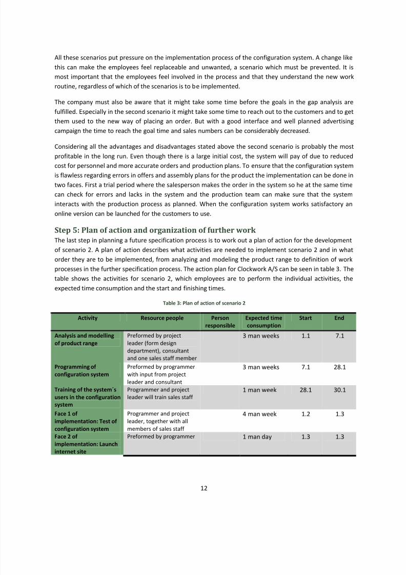
Step 5: Plan of action and organization of further work
The last step in planning a future specification process is to work out a plan of action for the development
of scenario 2. A plan of action describes what activities are needed to implement scenario 2 and in what
order they are to be implemented, from analyzing and modeling the product range to definition of work
processes in the further specification process. The action plan for Clockwork A/S can be seen in table 3. The
table shows the activities for scenario 2, which employees are to perform the individual activities, the
expected time consumption and the start and finishing times.
Table 3: Plan of action of scenario 2
Activity Resource people Person
responsible
Expected time
consumption
Start End
Analysis and modelling
of product range
Preformed by project
leader (form design
department), consultant
and one sales staff member
3 man weeks 1.1 7.1
Programming of
configuration system
Preformed by programmer
with input from project
leader and consultant
3 man weeks 7.1 28.1
Training of the system´s
users in the configuration
system
Programmer and project
leader will train sales staff
1 man week 28.1 30.1
Face 1 of
implementation: Test of
configuration system
Programmer and project
leader, together with all
members of sales staff
4 man week 1.2 1.3
Face 2 of
implementation: Launch
internet site
Preformed by programmer 1 man day 1.3 1.3
8/3/2019 Report Configuration
http://slidepdf.com/reader/full/report-configuration 14/21
13
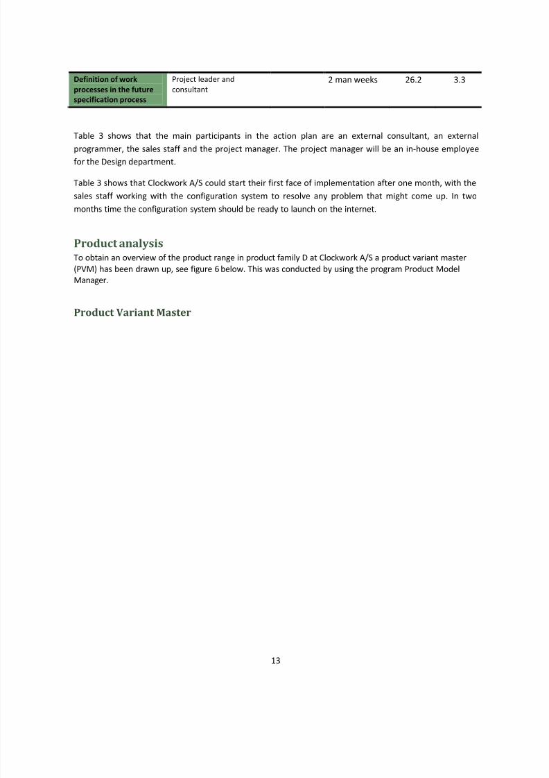
Definition of work
processes in the future
specification process
Project leader and
consultant
2 man weeks 26.2 3.3
Table 3 shows that the main participants in the action plan are an external consultant, an externalprogrammer, the sales staff and the project manager. The project manager will be an in-house employee
for the Design department.
Table 3 shows that Clockwork A/S could start their first face of implementation after one month, with the
sales staff working with the configuration system to resolve any problem that might come up. In two
months time the configuration system should be ready to launch on the internet.
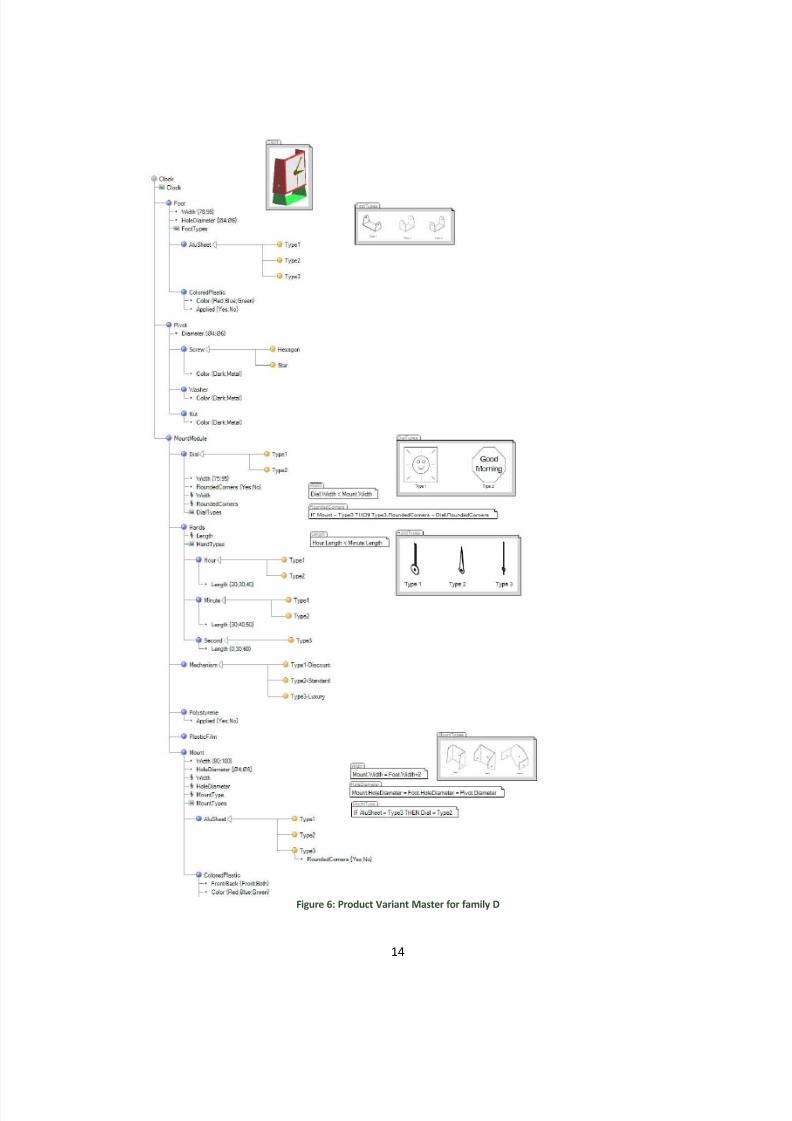
Product analysisTo obtain an overview of the product range in product family D at Clockwork A/S a product variant master
(PVM) has been drawn up, see figure 6 below. This was conducted by using the program Product ModelManager.
Product Variant Master
8/3/2019 Report Configuration
http://slidepdf.com/reader/full/report-configuration 15/21
14
Figure 6: Product Variant Master for family D
8/3/2019 Report Configuration
http://slidepdf.com/reader/full/report-configuration 16/21
15
The aim of a product variant master is to create an overview of the product range at the company. The
overview is used to simplify the evaluation of the product range in aspects such as variation in the product
range, if the product range is sufficient to the target market etc. It is also used to detect new combination
possibilities and identify unnecessary variations in the product range. There are different ways to approach
the structuring of a product variant master depending on what the goal is and for whom the product
variant master is made. In general there are three different approaches:
The customers view
The engineers view
The production view
In this case the salespersons place the most central role in the company and see the product from both the
customers and the engineers point of view. With that in mind the product variant master is constructed
after how the salesperson works when he/she selects the parts that are to be included in a specific
customized clock.
To be create a product variant master for the product the first step is to identify the part-of modules orparts of the product, i.e. the parts or modules that appears in all the products in the product family that is
been analyzed. In the product family analyzed in this assignment the following seven parts have been
identified:
Mount
Foot
Dial
Pivot
Mechanism
Hands
Plastic Film
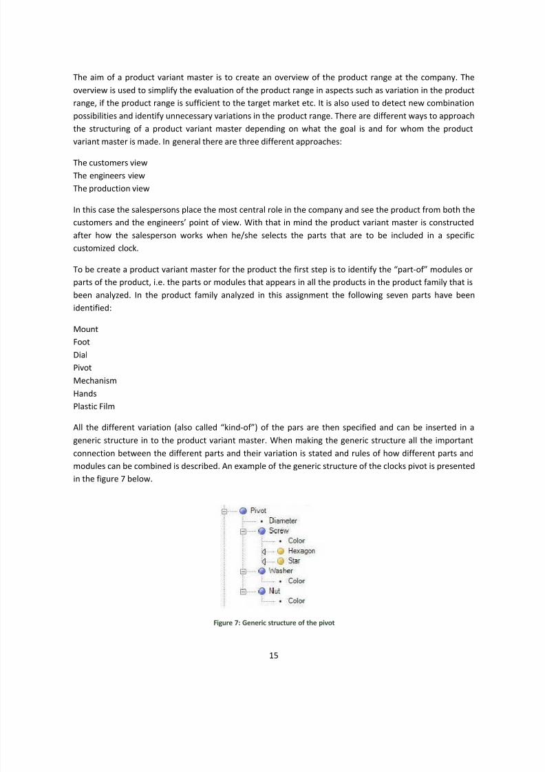
All the different variation (also called kind-of) of the pars are then specified and can be inserted in a
generic structure in to the product variant master. When making the generic structure all the important
connection between the different parts and their variation is stated and rules of how different parts and
modules can be combined is described. An example of the generic structure of the clocks pivot is presented
in the figure 7 below.
Figure 7: Generic structure of the pivot
8/3/2019 Report Configuration
http://slidepdf.com/reader/full/report-configuration 17/21
16
So in this case the product variant master describes which parts in the product family D can be combined
and all the variations of the different parts.
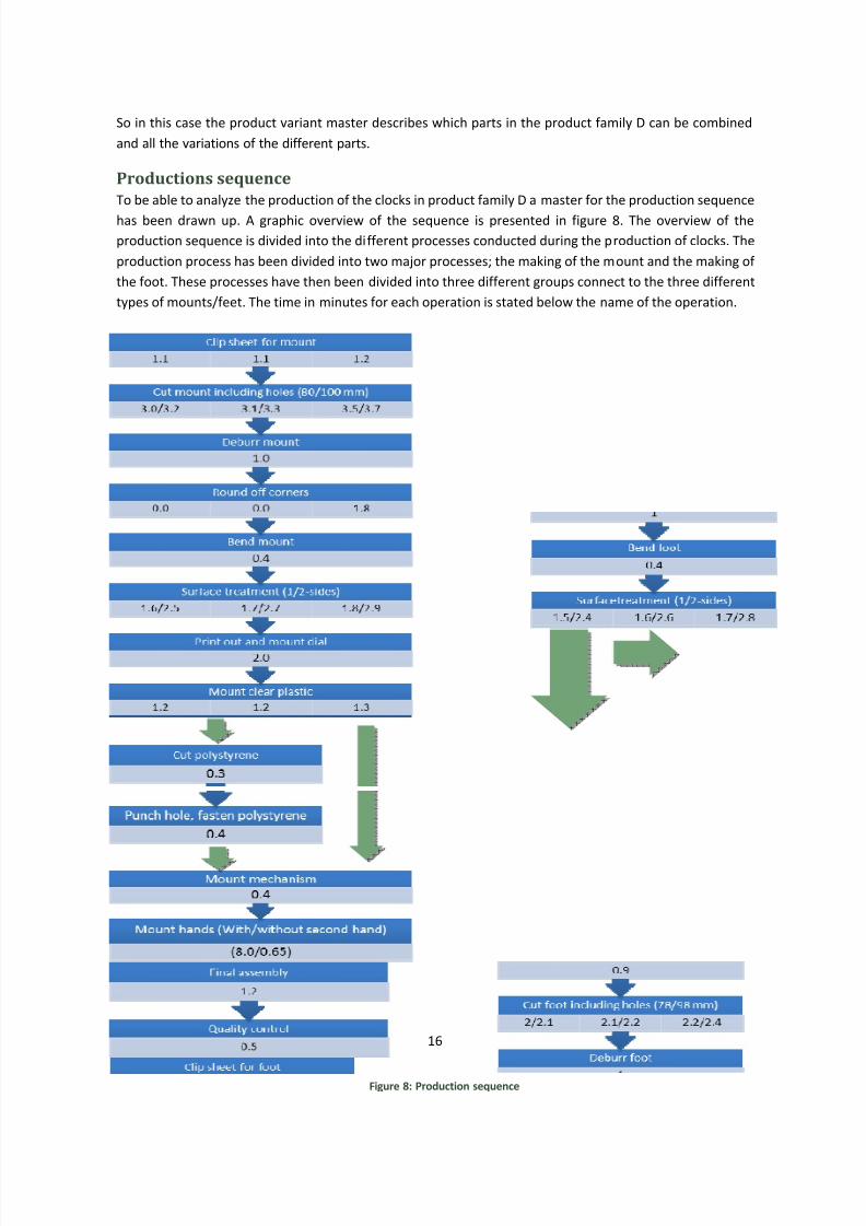
Productions sequence
To be able to analyze the production of the clocks in product family D a master for the production sequence
has been drawn up. A graphic overview of the sequence is presented in figure 8. The overview of the
production sequence is divided into the different processes conducted during the production of clocks. The
production process has been divided into two major processes; the making of the mount and the making of
the foot. These processes have then been divided into three different groups connect to the three different
types of mounts/feet. The time in minutes for each operation is stated below the name of the operation.
Figure 8: Production sequence
8/3/2019 Report Configuration
http://slidepdf.com/reader/full/report-configuration 18/21
17
Object Oriented AnalysisObject oriented analysis (OOA) is a way of visualizing the different steps a product has to go through in
order to be finished. The OOA can help structuring a complex system, because it gives a good overview of
the processes and parts. Another good reason to use the OOA is that it makes it easier to see which
components and processes are dependent on which thereby making it easier to distribute the different taskbetween the departments. This helps reducing the total finishing time since more departments can work on
the same time instead of waiting for each other for no reason when the system is not clear to all
departments. The system can be visualized in different ways: the class diagram and with the use of Class,
Responsibly and Collaboration (CRC) card.
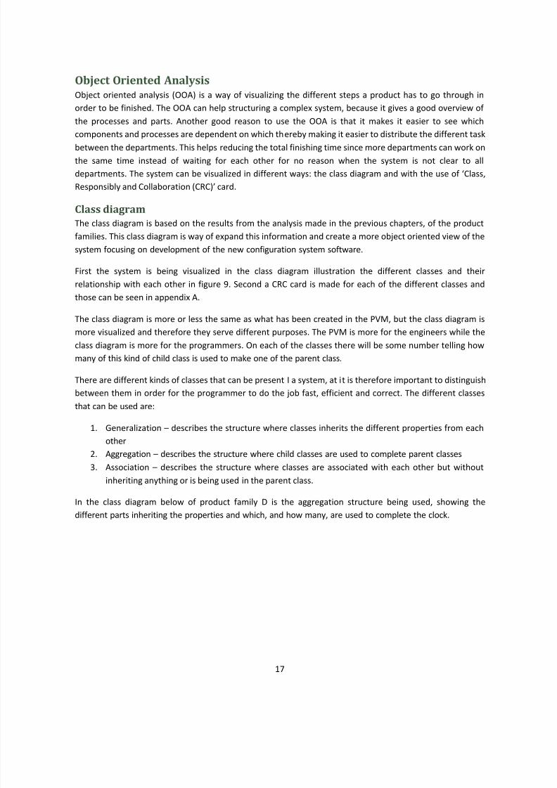
Class diagram
The class diagram is based on the results from the analysis made in the previous chapters, of the product
families. This class diagram is way of expand this information and create a more object oriented view of the
system focusing on development of the new configuration system software.
First the system is being visualized in the class diagram illustration the different classes and their
relationship with each other in figure 9. Second a CRC card is made for each of the different classes and
those can be seen in appendix A.
The class diagram is more or less the same as what has been created in the PVM, but the class diagram is
more visualized and therefore they serve different purposes. The PVM is more for the engineers while the
class diagram is more for the programmers. On each of the classes there will be some number telling how
many of this kind of child class is used to make one of the parent class.
There are different kinds of classes that can be present I a system, at it is therefore important to distinguish
between them in order for the programmer to do the job fast, efficient and correct. The different classes
that can be used are:
1. Generalization describes the structure where classes inherits the different properties from each
other
2. Aggregation describes the structure where child classes are used to complete parent classes
3. Association describes the structure where classes are associated with each other but without
inheriting anything or is being used in the parent class.
In the class diagram below of product family D is the aggregation structure being used, showing the
different parts inheriting the properties and which, and how many, are used to complete the clock.
8/3/2019 Report Configuration
http://slidepdf.com/reader/full/report-configuration 19/21
18
Figure 9: Class diagram of product family D
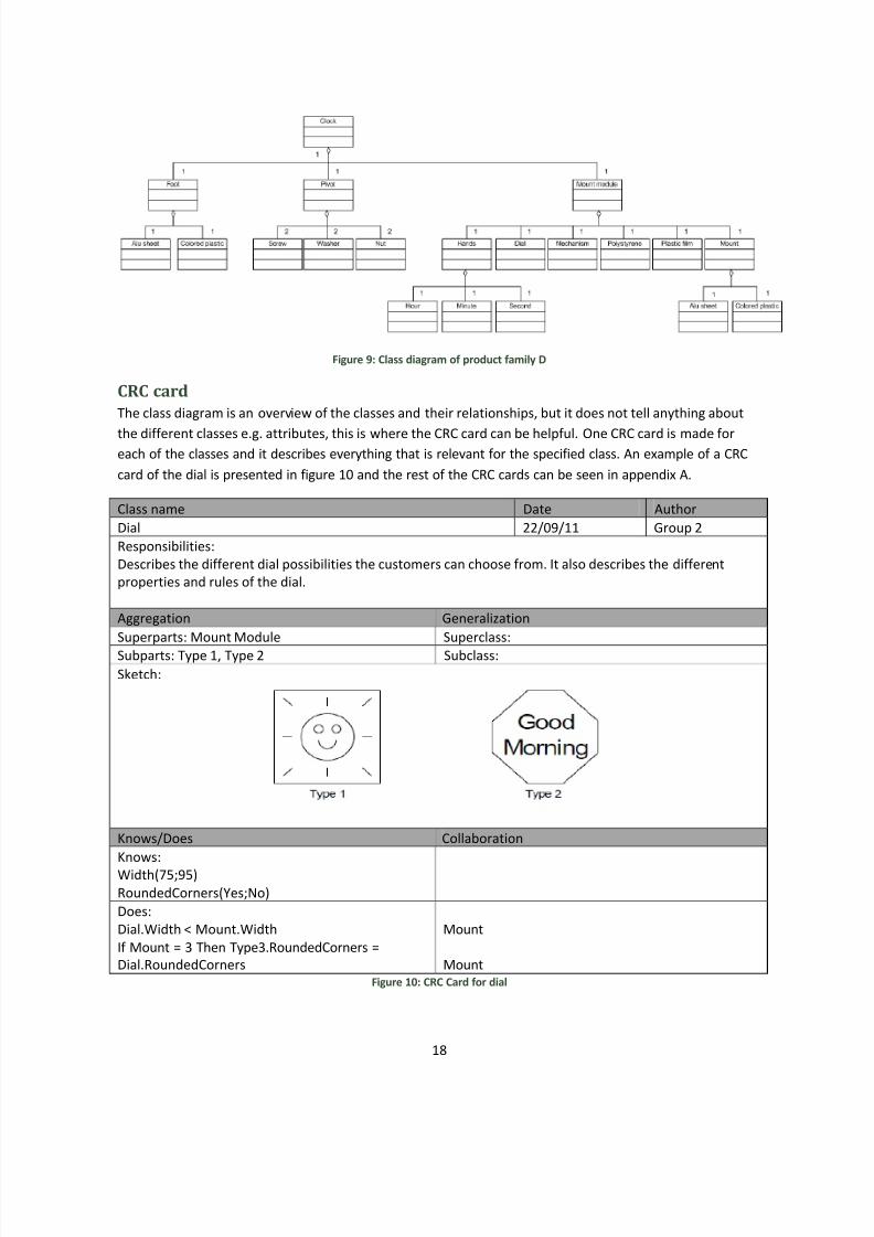
CRC card
The class diagram is an overview of the classes and their relationships, but it does not tell anything about
the different classes e.g. attributes, this is where the CRC card can be helpful. One CRC card is made foreach of the classes and it describes everything that is relevant for the specified class. An example of a CRC
card of the dial is presented in figure 10 and the rest of the CRC cards can be seen in appendix A.
Class name Date Author
Dial 22/09/11 Group 2
Responsibilities:
Describes the different dial possibilities the customers can choose from. It also describes the different
properties and rules of the dial.
Aggregation Generalization
Superparts: Mount Module Superclass:
Subparts: Type 1, Type 2 Subclass:
Sketch:
Knows/Does Collaboration
Knows:
Width(75;95)
RoundedCorners(Yes;No)
Does:
Dial.Width < Mount.Width
If Mount = 3 Then Type3.RoundedCorners =
Dial.RoundedCorners
Mount
Mount
Figure 10: CRC Card for dial
8/3/2019 Report Configuration
http://slidepdf.com/reader/full/report-configuration 20/21
19
The CRC cards describe the properties of relevant item. The different kinds of properties that are used in
the CRC cards are described below:
y Attributes the Knows, also known as the attributes, describes different properties that describe
all objects in the class. Attributes are used as guideline for the programmers when the system has
to be build
y Methods the Does, also known as the methods, describes how the different objects and classes
interact and are connected with each other. Methods describes in which way the programmer
should get the different classes to work together.
Object Oriented DesignThe purpose of object-oriented design is to use a set of objects that have specifications from the Object
Oriented Analysis and then, using these specifications, piece the objects together to form a larger object as
a whole. These specifications must also take into account any restrictions that may be involved with the
different objects.
A user/customer usually has some preferences or desired specifications for any product. In the case of
Clockwork A/S, when working with scenario 1 and 2, the user interface involves interaction on a computer,
from either the customer or salesperson. The user/customer is then always connected to the system, and
would get a constant update of any restraints based on specifications, comments or remarks from the
manufacturer, and an updated price based on choices made for the specifications.
The user/customer is also constantly updated on the appearance of the product. This would be done as the
specifications are made. Every time an input into the system is made, an image of the final product is
updated, giving the user/customer a feel of seeing the finished product come to life.
The experience would however be different depending on whether the customer is doing the process fromhome/office, or if it were a salesperson at the store. However, the process in which this is done would be
the same.
In Scenario 1, where the salesperson is present, he would see much more information about the different
parts that are included, and the general layout of his program would be different.
When it comes to scenario 2, where the customer is going through the process from home or at the office,
they would see a very simple and flowing design of the process. This would be done through Clockworks
A/Ss website, and it would be created so as to make sure the customer does not get confused or sees
information that is not relevant to them (part numbers, etc).
Scenario 3 involves most of the same steps in scenario 1, except the customer is not on location.
While the customer may have certain requirements to the product, they cannot always be filled due to
restrictions on the objects that are involved. They will specify these requirements to the
system/salesperson, and, if there are no restraints, the system will create a model for the customer.
8/3/2019 Report Configuration
http://slidepdf.com/reader/full/report-configuration 21/21
20
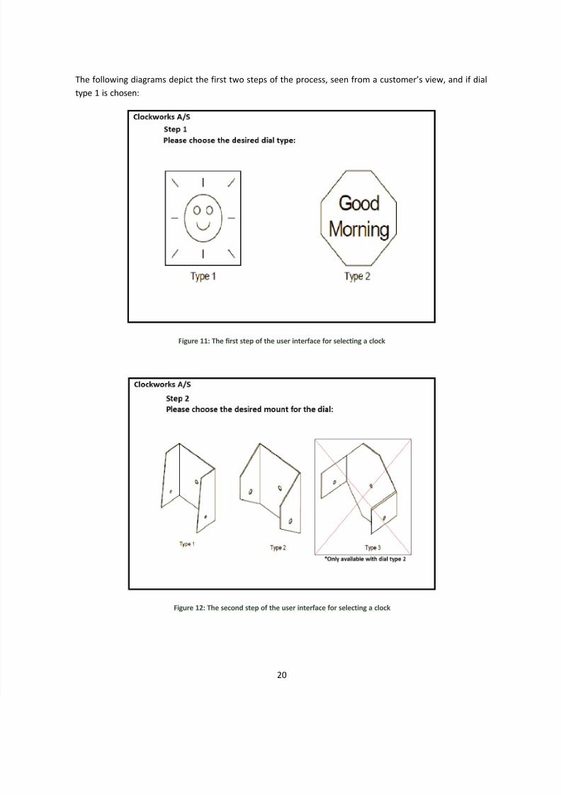
The following diagrams depict the first two steps of the process, seen from a customers view, and if dial
type 1 is chosen:
Figure 11: The first step of the user interface for selecting a clock
Figure 12: The second step of the user interface for selecting a clock