report documentation page form approved concepts such as phased-array, receive ... mimo radars are...
TRANSCRIPT

Standard Form 298 (Rev 8/98) Prescribed by ANSI Std. Z39.18
614-270-1361
W911NF-13-1-0280
63486-CS-RIP.2
Final Report
a. REPORT
14. ABSTRACT
16. SECURITY CLASSIFICATION OF:
1. REPORT DATE (DD-MM-YYYY)
4. TITLE AND SUBTITLE
13. SUPPLEMENTARY NOTES
12. DISTRIBUTION AVAILIBILITY STATEMENT
6. AUTHORS
7. PERFORMING ORGANIZATION NAMES AND ADDRESSES
15. SUBJECT TERMS
b. ABSTRACT
2. REPORT TYPE
17. LIMITATION OF ABSTRACT
15. NUMBER OF PAGES
5d. PROJECT NUMBER
5e. TASK NUMBER
5f. WORK UNIT NUMBER
5c. PROGRAM ELEMENT NUMBER
5b. GRANT NUMBER
5a. CONTRACT NUMBER
Form Approved OMB NO. 0704-0188
3. DATES COVERED (From - To)-
UU UU UU UU
17-06-2015 1-Aug-2013 31-Aug-2014
Approved for Public Release; Distribution Unlimited
Final Report: (DURIP) MIMO Radar Testbed for Waveform Adaptive Sensing Research
Under this DURIP grant, we have build a distributed MIMO software defined radar (SDR) testbed. The testbed consists of 14 micro SDR platforms with two transmit and one receive antennas and a standalone SDR with 4 transmit and 4 receive channels multiplexed to 32 x 32 antenna array through a switching matrix. These SDR platforms can adaptively modify both transmit waveforms and receive signal-processing tasks in real time. The radar platforms and associated antenna arrays are designed at X-Band with bandwidths unto 250 MHz.
The views, opinions and/or findings contained in this report are those of the author(s) and should not contrued as an official Department of the Army position, policy or decision, unless so designated by other documentation.
9. SPONSORING/MONITORING AGENCY NAME(S) AND ADDRESS(ES)
U.S. Army Research Office P.O. Box 12211 Research Triangle Park, NC 27709-2211
MIMO Radar Testbed, Software Defined Radar, Waveform Adaptation
REPORT DOCUMENTATION PAGE
11. SPONSOR/MONITOR'S REPORT NUMBER(S)
10. SPONSOR/MONITOR'S ACRONYM(S) ARO
8. PERFORMING ORGANIZATION REPORT NUMBER
19a. NAME OF RESPONSIBLE PERSON
19b. TELEPHONE NUMBEREmre Ertin
Emre Ertin
611103
c. THIS PAGE
The public reporting burden for this collection of information is estimated to average 1 hour per response, including the time for reviewing instructions, searching existing data sources, gathering and maintaining the data needed, and completing and reviewing the collection of information. Send comments regarding this burden estimate or any other aspect of this collection of information, including suggesstions for reducing this burden, to Washington Headquarters Services, Directorate for Information Operations and Reports, 1215 Jefferson Davis Highway, Suite 1204, Arlington VA, 22202-4302. Respondents should be aware that notwithstanding any other provision of law, no person shall be subject to any oenalty for failing to comply with a collection of information if it does not display a currently valid OMB control number.PLEASE DO NOT RETURN YOUR FORM TO THE ABOVE ADDRESS.
Ohio State University1960 Kenny Road
Columbus, OH 43210 -1016

31-Aug-2014

ABSTRACT
Number of Papers published in peer-reviewed journals:
Number of Papers published in non peer-reviewed journals:
Final Report: (DURIP) MIMO Radar Testbed for Waveform Adaptive Sensing Research
Report Title
Under this DURIP grant, we have build a distributed MIMO software defined radar (SDR) testbed. The testbed consists of 14 micro SDR platforms with two transmit and one receive antennas and a standalone SDR with 4 transmit and 4 receive channels multiplexed to 32 x 32 antenna array through a switching matrix. These SDR platforms can adaptively modify both transmit waveforms and receive signal-processing tasks in real time. The radar platforms and associated antenna arrays are designed at X-Band with bandwidths unto 250 MHz.
(a) Papers published in peer-reviewed journals (N/A for none)
Enter List of papers submitted or published that acknowledge ARO support from the start of the project to the date of this printing. List the papers, including journal references, in the following categories:
(b) Papers published in non-peer-reviewed journals (N/A for none)
(c) Presentations
Received Paper
TOTAL:
Received Paper
TOTAL:

Number of Non Peer-Reviewed Conference Proceeding publications (other than abstracts):
Peer-Reviewed Conference Proceeding publications (other than abstracts):
Number of Peer-Reviewed Conference Proceeding publications (other than abstracts):
0.00Number of Presentations:
Non Peer-Reviewed Conference Proceeding publications (other than abstracts):
(d) Manuscripts
Received Paper
TOTAL:
06/12/2015
Received Paper
1.00 Siddharth Baskar, Emre Ertin. A Software Defined Radar Platform for Waveform Adaptive MIMO Radar Research , IEEE International Radar Conference. 11-MAY-15, . : ,
TOTAL: 1
Received Paper
TOTAL:

Books
Number of Manuscripts:
Patents Submitted
Patents Awarded
Awards
Graduate Students
Names of Post Doctorates
Received Book
TOTAL:
Received Book Chapter
TOTAL:
PERCENT_SUPPORTEDNAME
FTE Equivalent:
Total Number:
PERCENT_SUPPORTEDNAME
FTE Equivalent:
Total Number:

Sub Contractors (DD882)
Names of Faculty Supported
Names of Under Graduate students supported
Names of Personnel receiving masters degrees
Names of personnel receiving PHDs
Names of other research staff
Number of graduating undergraduates who achieved a 3.5 GPA to 4.0 (4.0 max scale):Number of graduating undergraduates funded by a DoD funded Center of Excellence grant for
Education, Research and Engineering:The number of undergraduates funded by your agreement who graduated during this period and intend to work
for the Department of DefenseThe number of undergraduates funded by your agreement who graduated during this period and will receive
scholarships or fellowships for further studies in science, mathematics, engineering or technology fields:
Student MetricsThis section only applies to graduating undergraduates supported by this agreement in this reporting period
The number of undergraduates funded by this agreement who graduated during this period:
0.00
0.00
0.00
0.00
0.00
0.00
0.00
The number of undergraduates funded by this agreement who graduated during this period with a degree in science, mathematics, engineering, or technology fields:
The number of undergraduates funded by your agreement who graduated during this period and will continue to pursue a graduate or Ph.D. degree in science, mathematics, engineering, or technology fields:......
......
......
......
......
PERCENT_SUPPORTEDNAME
FTE Equivalent:
Total Number:
PERCENT_SUPPORTEDNAME
FTE Equivalent:
Total Number:
NAME
Total Number:
NAME
Total Number:
PERCENT_SUPPORTEDNAME
FTE Equivalent:
Total Number:
......
......

Inventions (DD882)
Scientific Progress
Technology Transfer

Final Report
(DURIP) MIMO Radar Testbed for
Waveform Adaptive Sensing Research
Contract/Grant # W911NF-13-1-0280
PI: Emre Ertin
Department of Electrical and Computer Engineering
The Ohio State University
Columbus, OH
Foreword Microwave radar systems are crucial components of any standoff sensor system due to their all-weather
capabilities and proven performance for tracking, imaging, and situational awareness. However, complex electromag-
netic wave propagation environment such as urban area with clutter discrete can make separation of target signatures
and propagation channel effects difficult; a radar capable of adaptively varying its transmit waveforms for probing
the environment, including the use of multiple transmit/receive antennas can provide distinct gains in separating these
effects.
Under this DURIP program we build a collaborative research resource based on software defined radar (SDR) plat-
forms that can adaptively modify both transmit waveforms and receive signal-processing tasks in real time. This
collaborative research resource will be utilized by faculty and students of the Ohio State University, University of
Michigan, Massachusetts Institute of Technology and Arizona State University. The testbed consists of 14 Micro SDR
Platforms with 2 transmit and 1 receive antennas and a standalone high performance multichannel SDR multiplexed
to a 32 x 32 antenna array.

Final Report (DURIP) MIMO Radar Testbed for Waveform Adaptive Sensing Research
Contents
1 Problem Statement 1
2 Design Summary and Results 3
2.1 Novel Hybrid Up and Downconversion Stage Design . . . . . . . . . . . . . . . . . . . . . . . . . . 4
2.2 RF Frontend Design . . . . . . . . . . . . . . . . . . . . . . . . . . . . . . . . . . . . . . . . . . . . 6
2.3 Antenna Switching Matrix . . . . . . . . . . . . . . . . . . . . . . . . . . . . . . . . . . . . . . . . 9
2.4 Benchtop Measurements . . . . . . . . . . . . . . . . . . . . . . . . . . . . . . . . . . . . . . . . . 10
2.5 Experimental Results . . . . . . . . . . . . . . . . . . . . . . . . . . . . . . . . . . . . . . . . . . . 11
Appendix A Schematics for X-Band Custom RF Frontend 13
Appendix B Schematics for MIMO Antenna Switching Matrix 27
1 Problem Statement
MIMO radar systems which can transmit independent waveforms on multiple antennas have been suggested for im-
proving detection, parameter estimation and clutter suppression capabilities. While many traditional multi-antenna
radar concepts such as phased-array, receive beamforming, STAP, polarimetry, and interferometry can be seen as spe-
cial cases of MIMO radar, the distinct advantage of a multi-antenna radar system with independent transmit waveforms
is the increased number of degrees of freedom leading to improved resolution, detection and parameter estimation.
MIMO system benefits can be realized in the form of reduced pulse repetition frequency (PRF), larger spot sizes,
and/or lower transmit energy.
In the literature, MIMO radars are distinguished based on the geometry of the receive and transmit centers. There are
two main categories. MIMO radars with widely separated transmit and receive arrays provide statistically independent
measurements of the illuminated scene and are categorized as a statistical MIMO radars. MIMO radar systems with
widely separated antennas employs spatially diverse transmitters and receivers to overcome target fading effects [1],
[2] or to estimate a target’s location with high resolution [3, 4]. If antennas are relatively close to each other, so that
1

Final Report (DURIP) MIMO Radar Testbed for Waveform Adaptive Sensing Research
for each scatterer in the illuminated scene the angle of arrival is approximately the same for all phase centers, then
the system is referred to as a coherent MIMO radar. The main advantage of the coherent MIMO radar is its ability to
synthesize a large virtual array with fewer antenna elements for improved spatial processing. The OSU micro SDR
platforms we developed will enable research in both modalities as well as novel hybrid modes combining elements of
the two in a multi-static setting.
In this project our focus is development of a low power, short range versatile radar system that combines a high
speed FPGA digital back-end with sideband digital/analog and analog/digital converters with a custom built RF Fron-
tend. The key idea is software defined radar system is to sample the transmit/receive waveforms using high speed
digital/analog and analog/digital converters and to implement key processing stages using programmable digital hard-
ware [5]. This allows the SDR to, for example, change modes from detection to tracking, or adapt its waveform based
on environmental conditions and or information derived from previous radar interrogations. Increasing number of
transmit and receive channels with the use of antenna switching matrix for MIMO applications is discussed in [6].
The use of MIMO radar for studying wideband radar array signal processing in short range indoor application has
been demonstrated in [7], where non-adaptive linear frequency FM waveforms are used. Application of waveform
adaptation for matching transmitted waveform to the target’s impulse response improves target detection and aids in
target identification [8, 9]. However, experimental verification of these ideas have not been widely explored.
Under this DURIP program we build a collaborative research resource based on software defined radar (SDR) plat-
forms that can adaptively modify both transmit waveforms and receive signal-processing tasks in real time. The testbed
consists of 14 Micro SDR Platforms with 2 transmit and 1 receive antennas and a standalone high performance multi-
channel SDR multiplexed to a 32 x 32 antenna array. This two-tiered architecture allows research and experimentation
in many domains of active sensing. Specifically we focus on three scenarios:
• Micro SDRs can be deployed to perform non-coherent fusion of backscatter returns (also known as statistical
MIMO radar) to decrease fluctuations in target returns to selective fading through spatial diversity. The Micro
SDRs can modify their transmit waveforms and pulse repetition frequencies cooperatively to adapt changes in
the background and target returns as well as scene complexity. In addition micro SDRs can be mounted on
robotic platforms to optimize the collection geometry and derive fusion research with other modalities such as
2

Final Report (DURIP) MIMO Radar Testbed for Waveform Adaptive Sensing Research
EO, IR cameras and acoustic sensors.
• Co-located MIMO array paired with the switchable antenna array matrix can emulate airborne collections with
its 32x32 antenna matrix. Focus will be on space-time adaptive (STAP) techniques for detection of slow moving
targets against stationary clutter. Specifically, the performance of the MIMO STAP techniques critically hinges
on the structure of the clutter covariance matrix, and to our best knowledge the testbed will be unique in its data
collection capability for massive MIMO arrays.
• Alternatively the two components of the testbed can be combined to provide a novel operation scenario, where
the coherent MIMO array is used to emulate illumination by an airborne platform with multi-static passive
sensing by micro-SDR platforms from diverse set of aspect angles.
There are many other scenarios where the components of the testbed can be used to derive research in active sensing.
This report focuses on details of the hardware design for the SDR platforms.
Figure 1: Waveform adaptive MIMO SDR
2 Design Summary and Results
The operational principle of a software defined radar system is to sample the transmit/receive waveforms using high
speed digital/analog and analog/digital converters and to implement key processing stages using programmable digital
3

Final Report (DURIP) MIMO Radar Testbed for Waveform Adaptive Sensing Research
hardware. The block diagram for the proposed software defined radar system is given in Figure 1. A high speed
digital waveform generator is used to construct independent waveforms for a set of transmit antennas, and produces
a synchronized multi-channel baseband transmit signal which is mixed and amplified for transmission. In the receive
signal chain, the received energy is filtered, amplified, and downconverted by an RF module, sampled in the baseband
bandwidth synchronously across the multiple channels, and passed to an FPGA-based real-time signal processor for
multi-channel coherent processing. The adaptive operation of the system is controlled by the information driven active
sensing layer which allocates system resources to achieve sensing objectives by supplying the user with ATR primitives
(target detections, target track and ID). The current implementation of the micro SDR platform is given in Figure 2
with the custom X-Band RF frontend developed at OSU on the top and the off the shelf high speed digital backend at
the bottom. Design details for the first spiral of the design cycle were reported earlier in [10].
Figure 2: OSU Micro SDR platform
2.1 Novel Hybrid Up and Downconversion Stage Design
In an idealized model of software defined radar analog-to-digital and digital-to-analog conversion will be accomplished
at the RF frequency band without analog conversion stages. This way, down and up-conversion will be performed in the
4

Final Report (DURIP) MIMO Radar Testbed for Waveform Adaptive Sensing Research
digital domain limiting the analog components to high-dynamic range low noise amplifier (LNA) and power transmit
amplifiers. Unfortunately, existing ADC performance is far from operating with high dynamic range in the radar bands
of interest at multiple GHz. In addition, real time signal processing tasks of frequency conversion, digital filtering will
require multiple FPGA/DSPs operating on interleaved data to cope with the large sampling rate of receive and transmit
signals. Therefore, RF fronted in a software defined radar system have to include up and down conversion stages.
There are many options of implementing conversion stages. The most common architecture is heterodyne receiver
structure that uses an conversion stages at multiple intermediate frequencies (IF) to implement image suppression and
channel selection. Heterodyne receivers can achieve high sensitivity and channel selectivity, DC offset is eliminated
in the bandpass filters following each IF conversion. However, large number of components including image rejection
filters are required for multiple conversion stages increasing the complexity of the design. At the other end of the
spectrum of the receiver structures are Zero-IF receivers that employ single quadrature demodulator to bring the RF
passband signal to complex baseband. Zero-IF receivers are not subject to the image problem common to receivers
with intermediate frequency conversion stages. However, significant DC offsets at the output of quadrature mixers as
a result of LO leakage signal mixing with itself.
In our design we employ a hybrid structure relying on the oversampling design of the DAC which can generate
waveforms at digitally generated IF frequencies. On transmit, we directly generate a pass band signal around a lowIF
frequency of 187.5 MHz with a bandwidth of 125 MHz using the oversampling DACs in our system. Each DAC is
used to generate an independent transmit waveform as real-valued pass band signal. For each transmit channel, low-IF
pass-band signal is up-converted to X-band using a single channel mixer. We use a RF pass-band filter to reject the
image and LO leakage. On receive we use a RF band-pass filter to limit the wideband noise and a zero-IF receiver
with quadrature downconversion with the same LO that generated the transmit signal. As a result the received signal
is passband signal at the output of down-conversion mixer’s I and Q outputs. Next, we employ standard bandpass
sampling in the second Nyquist zone, to alias the digitally generated low-IF signal to the baseband. We note that in
our system DAC and ADC use a single clock -source eliminating the problem of clock-jitter limiting the performance
of band-pass sampling systems in practice. In addition low-IF bandpass sampling system enables us to use a DC-
blocker at the output of quadrature mixer output, eliminating the DC-offset problem common to zero-IF receivers.
Figure 3 shows the novel hybrid up and downconversion employed in our design
5

Final Report (DURIP) MIMO Radar Testbed for Waveform Adaptive Sensing Research
Figure 3: Frequency content of the transmit baseband, transmit passband and receive baseband signals. Bandpass
sampling aliasing is depicted as dashed lines.
The custom RF Frontend built at Ohio State features two independent Transmit (TX) and a single Receive (RX) channel
multiplexed to four receive antennas. The instantaneous bandwidth of the system is 250 MHz. The RF Frontend
operates at X-band and includes an onboard Phase Locked Loop (PLL) and Voltage Controlled Oscillator (VCO) to
generate Local Oscillator (LO) signal from a local GPS conditioned oven-controlled 10 MHz reference.
2.2 RF Frontend Design
Figure 4 shows the block diagram of Receiver. The inputs of four RX antennas are fed to a Low Noise Amplifier
(LNA) whose output is connected to receive frontend through switching circuit. Since it is likely that the antennas will
be connected to the rest of the RF system by long cables, including the LNA close to the antenna reduces the impact
6

Final Report (DURIP) MIMO Radar Testbed for Waveform Adaptive Sensing Research
Figure 4: Block Diagram of receiver
of cable loss on receiver’s overall noise figure. The signal from the switch is filtered through a resonant coupled
Band Pass Filter (BPF) to filter any blocker and image signal. The filtered signal is down converted by In-phase and
Quadrature (IQ) mixer and the down converted signal is amplified by an IF amplifier. The amplified signal is filtered
by a low pass filter and digitized by high speed ADC. In order to minimize the phase and amplitude imbalance in IQ
signal, the I and Q channels are routed symmetrically and dual IF amplifier is used for amplification.
Figure 5: Block Diagram of Transmitter
Figure 5 shows the block diagram of Transmitter. The IF signal is generated by the DAC at 250 MHz and 0 dBm
power. The IF single is filtered by a Low Pass Filter (LPF) to remove digital copies and amplified by a base band
amplifier. The amplified signal is up converted to X-Band using a double-balanced mixer and further amplified by a
high Power Amplifier (PA). The amplified signal is filtered by a resonant coupled band pass filter to remove mixer and
power amplifier inter-modulation components.
The on board PLL requires a reference signal of 50 MHz signal for locking, however the GPS conditioned reference
is designed to generate a 10 MHz signal. Hence a 5X frequency multiplier is used and a combination of Low Pass
and High Pass filters were used to remove harmonics from the multiplier. The reference signal is further amplifier
to compensate for the loss during frequency multiplication. This resulting 50 MHz signal is used as reference by the
7
Final Report (DURIP) MIMO Radar Testbed for Waveform Adaptive Sensing Research
PLL. Output of PLL is divided equally by a 3 dB splitter and further amplified by driver amplifiers and this amplified
signal is used by the mixers for up and down conversion. The PLL used on the SDR works with a standard four wire
Serial Peripheral Interface (SPI). MSP430F1611 micro controller is used for configuring the registers on the PLL upon
power up.
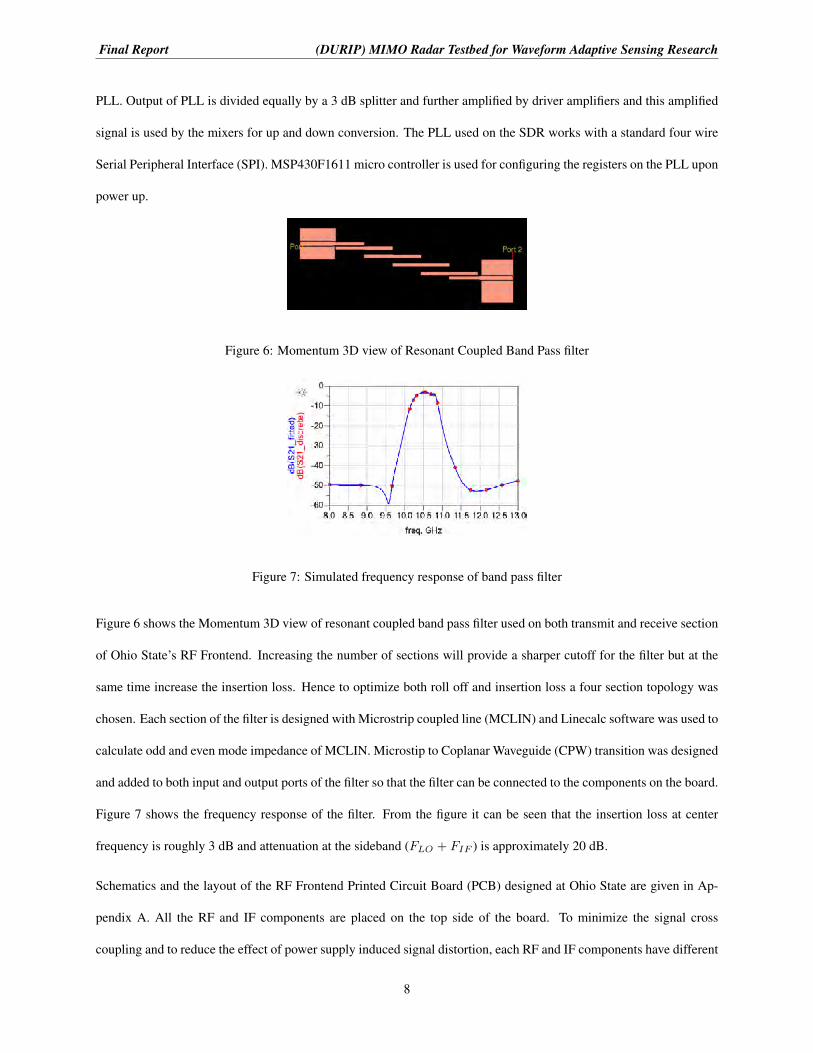
Figure 6: Momentum 3D view of Resonant Coupled Band Pass filter
Figure 7: Simulated frequency response of band pass filter
Figure 6 shows the Momentum 3D view of resonant coupled band pass filter used on both transmit and receive section
of Ohio State’s RF Frontend. Increasing the number of sections will provide a sharper cutoff for the filter but at the
same time increase the insertion loss. Hence to optimize both roll off and insertion loss a four section topology was
chosen. Each section of the filter is designed with Microstrip coupled line (MCLIN) and Linecalc software was used to
calculate odd and even mode impedance of MCLIN. Microstip to Coplanar Waveguide (CPW) transition was designed
and added to both input and output ports of the filter so that the filter can be connected to the components on the board.
Figure 7 shows the frequency response of the filter. From the figure it can be seen that the insertion loss at center
frequency is roughly 3 dB and attenuation at the sideband (FLO + FIF ) is approximately 20 dB.
Schematics and the layout of the RF Frontend Printed Circuit Board (PCB) designed at Ohio State are given in Ap-
pendix A. All the RF and IF components are placed on the top side of the board. To minimize the signal cross
coupling and to reduce the effect of power supply induced signal distortion, each RF and IF components have different
8

Final Report (DURIP) MIMO Radar Testbed for Waveform Adaptive Sensing Research
Figure 8: Spectrum of Transmitter with 250 MHz IF signal at -3 dbm power
bias and power supply. The RF Frontend is fabricated on a 4 layer RO4350B substrate and all the RF traces were
designed and simulated on Advanced Design System (ADS) software. The board was designed using Allegro PCB
editor software.
2.3 Antenna Switching Matrix
Both the micro SDR and standalone multi-channel MIMO SDR unit RF fronted units are designed for interfacing
with antenna arrays for multiplexing large number of receive and antenna arrays. For the standalone array we have
designed a 32 TX and 32 RX antenna array to interface to 4 transmit and 4 receive channels on the RF frontend. 32
Tx and 32 Rx antennas are printed on a circuit board in two rows parallel to each other. The system can emulate linear
airborne motion along its long axis by sequentially selecting 4 consecutive Rx antennas out of the available 32 receive
and transmit antennas. For each pulse four independent waveforms are transmitted from four transmitters and received
by four antennas that are electronically selected. At subsequent pulses, waveforms transmitted from different set of
four receiving and transmit antennas shifted spatially k�/2 relative to the previous set, where � is the wavelength and
k is an integer.
The emulated airborne speed is given by the spacing between elements of the synthesized receivers arrays in subse-
quent pulses and the pulse repetition frequency. Each receive antenna has an LNA mounted on the back to minimize
the noise figure. Then we use set of four 4⇥1 switches followed by another 4⇥1 switch to allow routing of 32 antennas
to the 4 physical channels on the fronted. Schematics for the switching matrix are given in Appendix B.
9

Final Report (DURIP) MIMO Radar Testbed for Waveform Adaptive Sensing Research
2.4 Benchtop Measurements
All measurements were performed in lab environment with IF signal generated with Agilent Analog Signal generator
and measured with Agilent PXA Spectrum Analyzer. The receiver is characterized with transmit signal looped back
to receiver with 40 dB attenuation. Figure 8 shows the transmit spectrum with 250 MHz signal at IF. The desired
signal appears at (FLO � FIF ). Along with the desired signal, LO signal is also present due to the finite LO-RF
isolation of the mixer. However on the receiver side, during down conversion this LO leakage signal will be down
converted to Direct Current (DC) and will be blocked by capacitors. In addition to this FLO + FIF and FLO � 2FIF
(third order inter-modulation) are present at the output. The highest interfering signal is the LO leakage with 10dB
suppression
Figure 9: Transmitter Two Tone test result (tones centered at 250 MHz with 25 MHz frequency separation)
Figure 9 shows two tone test result of transmitter. The two tones are -3 dBm in power and are centered at 250 MHz and
with 25 MHz separation between them. As seen in any upconversion transmitter, due to the non linearity of mixer and
power amplifiers, the two tones interact with each other and produce second and third order inter-modulation products.
The important component for signal analysis is third order intermodulation products. From the figure the third order
inter modulation products are at 2F2 � F1 and 2F1 � F2. Measured IM3 value is 16.44 dB which is consistent with
the theoretical value calculated from specification of the components.
Table 1 summarizes measured critical performance metrics of the Transmitter and Receiver.
10

Final Report (DURIP) MIMO Radar Testbed for Waveform Adaptive Sensing Research
Table 1: Critical Specifications of Transmitter and Receiver
Specification Transmitter Receiver
Gain 23.40 dB 24.20 dB
OIP3 33.99 dBm 29.20 dBm
P1dB -0.30 dBm -7.82 dBm
Noise Figure NA 2.76 dB
Figure 10: Range-Doppler Map of a vehicle for the two transmit channels
2.5 Experimental Results
We have validated the micro SDR platform performance through field tests. For the particular field test we have used
two independent waveforms of 120 MHz Bandwidth: one up-chirp and one down-chirp on the two transmit antennas.
The two waveforms are generated coherently in the FPGA and therefore orthogonal at each time in the frequency
domain. The backscatter energy from the objects in the field of view are sampled using a single receive channel
operating at 250 MSamples/sec at I and Q channels. After baseband filtering and down-sampling the responses to
each transmit channel is captured through match filtering with its associated waveform. We use a pulse repetition
11

Final Report (DURIP) MIMO Radar Testbed for Waveform Adaptive Sensing Research
Figure 11: Range-Doppler Map of two dismounts walking at different speeds for the two transmit channels
frequency of 1KHz and use pulses that are 100 µsec long. The coherent processing interval (CPI) Is 64 pulses. The
returns are filtered in Doppler to suppress returns form stationary clutter.
In the first experiment returns from a vehicle moving away from the radar are captured. The Range-Doppler map for
the two transmit channels captured through a single channel are given in Figure 10. The target returns are clearly
visible and show symmetry in the two channels. In the second experiment we have two human subjects moving away
from the antenna at different speeds and roughly at the same range of about 10 meters. The Range-Doppler map
of the two transmit channels are given in Figure 11. Again the target returns are clearly visible and separated in
Doppler.
12

Final Report (DURIP) MIMO Radar Testbed for Waveform Adaptive Sensing Research
Appendix A Schematics for X-Band Custom RF Frontend
13

55
44
33
22
11
DD
CC
BB
AA
MISC
Software Defined Radar: X-Band RF Frontend
Vin_unreg
Vin_unregVin_unreg
Vin_unregVin_unreg
Vin_unreg
Vin_unreg
Vin_unreg
Vin_unreg
Vin_unreg
Vin_unreg
SC
K
SD
I
SD
O
SE
N
CE
N
3V_D
IGITA
LV
IN_R
EG
5.5V_A
NA
LOG
5.5V_A
NA
LOG
Title
Size
Docum
ent Num
berR
ev
Date:
Sheet
of1
1
Title
Size
Docum
ent Num
berR
ev
Date:
Sheet
of1
1
Title
Size
Docum
ent Num
berR
ev
Date:
Sheet
of1
1
C174
22uFC
17422uF
U27
Screw
1.4
U27
Screw
1.4 nc1
C209
22uFC
20922uF
J10
JAC
K 37341
J10
JAC
K 37341
1 2
U25
Screw
1.4
U25
Screw
1.4 nc1
C206
1uFC
2061uF
C205
0.1uFC
2050.1uF
J11
JAC
K 37341
J11
JAC
K 37341
1 2
L10
240-2411-1-ND
L10
240-2411-1-ND
C177
10uFC
17710uF
U26
Screw
1.4
U26
Screw
1.4 nc1
C192
10nFC
19210nF
U44
TPS
54427U
44TP
S54427
VIN
8
EN
1
VR
EG
53
SS
4
GND5
PP9
VFB
2
SW
6
VB
ST
7
C200
10nFC
20010nF
J13
JAC
K 37341
J13
JAC
K 37341
1 2
C190
0.1uFC
1900.1uF
C196
10nFC
19610nF
U32
Screw
1.4
U32
Screw
1.4 nc1
U23
Screw
1.4
U23
Screw
1.4 nc1
L13
3.6uH
L13
3.6uH
J4JAC
K 37341
J4JAC
K 37341
1 2
C186
10nFC
18610nF
C198
10nFC
19810nF
C211
0.1uFC
2110.1uF
J5JAC
K 37341
J5JAC
K 37341
1 2
C179
100nFC
179100nF
C191
0.1uFC
1910.1uF
U5TLW
-106-05-T-D
U5TLW
-106-05-T-D
GN
D1
SC
K3
SD
I5
SD
O7
SE
N9
CE
N11
DV
CC
_12
DV
CC
_24
NC
_16
NC
_28
NC
_310
NC
_412
U19
Screw
1.4
U19
Screw
1.4 nc1
L11
240-2411-1-ND
L11
240-2411-1-ND
U34
Screw
1.4
U34
Screw
1.4 nc1
J14
JAC
K 37341
J14
JAC
K 37341
1 2
R42
10K
R42
10K
C195
0.1uFC
1950.1uF
J9JAC
K 37341
J9JAC
K 37341
1 2
U24
Screw
1.4
U24
Screw
1.4 nc1
C176
0.1uFC
1760.1uF
R43
140kR
43140k
C203
10nFC
20310nF
C197
0.1uFC
1970.1uF
J3JAC
K 37341
J3JAC
K 37341
1 2
C207
0.008uFC
2070.008uF
C193
0.1uFC
1930.1uF
J17
JAC
K 37341
J17
JAC
K 37341
1 2
C185
0.1uFC
1850.1uF
C178
4.7uFC
1784.7uF
C201
0.1uFC
2010.1uF
L9240-2411-1-ND
L9240-2411-1-ND
C199
0.1uFC
1990.1uF
C187
10nFC
18710nF
C188
0.1uFC
1880.1uF
D14
LED
D14
LED
R44
22.1KR
4422.1K
C208
7pFC
2087pF
C204
22uFC
20422uF
U18
Screw
1.4
U18
Screw
1.4 nc1
C194
10nFC
19410nF
C210
22uFC
21022uF
L12
490-1041-2-ND
L12
490-1041-2-ND
C189
10nFC
18910nF
U20
Screw
1.4
U20
Screw
1.4 nc1
C180
0.1uFC
1800.1uF
U33
Screw
1.4
U33
Screw
1.4 nc1
C212
0.1uF
C212
0.1uF
R131
1K R131
1K
C181
10uFC
18110uF
J12
JAC
K 37341
J12
JAC
K 37341
1 2
C175
100nFC
175100nF
J8JAC
K 37341
J8JAC
K 37341
1 2

55
44
33
22
11
DD
CC
BB
AA
Software Defined Radar: X-Band RF Frontend
TX-RX LO Drivers
RX
_LO_A
MP
_IN
TX_LO
_AM
P_IN
TX_LO
RX
_LO_A
MP
_IN
Vdd_LO
_1V
dd_AM
P_1
Vdd_AMP_1
Vdd_LO
_1
TX_LO
_AM
P_IN
Vdd_LO
_2V
dd_AM
P_2
Vdd_AMP_2
TX_LO
Vdd_LO
_2
TX_LO
_1
TX_LO
_2
5.5V_A
NA
LOG
5.5V_A
NA
LOG
PLL_O
UT
RX
_LO
Title
Size
Docum
ent Num
berR
ev
Date:
Sheet
of1
1
Title
Size
Docum
ent Num
berR
ev
Date:
Sheet
of1
1
Title
Size
Docum
ent Num
berR
ev
Date:
Sheet
of1
1
C117
22uF_CC
11722uF_C
C116
10uFC
11610uF
C120
1000pFC
1201000pF
C119
4.7uFC
1194.7uF
U29A
DP
3330-5
U29A
DP
3330-5
ER
R3
IN2
SD6
GND4
NR5
OU
T1
C121
100pFC
121100pF
U48
PD
-0434SM
U48
PD
-0434SM
IN1
OU
T12
OU
T23
U28
HM
C441LC
3B
U28
HM
C441LC
3B
GN
D1
1
RFIN
2
GN
D2
3
GND34
GND45
GND56
GN
D7
7R
FOU
T8
GN
D8
9
GND910
Vdd11
GND1012
GND1113
C115
100pFC
115100pF
U40
PD
-0434SM
U40
PD
-0434SM
IN1
OU
T12
OU
T23
C114
1000pFC
1141000pF
C113
4.7uFC
1134.7uF
C124
0.1uFC
1240.1uF
C123
22uF_CC
12322uF_C
U30
HM
C441LC
3B
U30
HM
C441LC
3B
GN
D1
1
RFIN
2
GN
D2
3
GND34
GND45
GND56
GN
D7
7R
FOU
T8
GN
D8
9
GND910
Vdd11
GND1012
GND1113
C122
10uFC
12210uF
C118
0.1uFC
1180.1uF
U31A
DP
3330-5
U31A
DP
3330-5
ER
R3
IN2
SD6
GND4
NR5
OU
T1

55
44
33
22
11
DD
CC
BB
AA
Software Defined Radar: X-Band RF Frontend
TX and RX Mixer
RX
_RF_IN
RX
_RF_IN
RFIN
2R
FIN1
RX
_IF_AM
P2_IN
RX
_IF_AM
P1_IN
RX
_LO
TX_P
A_IN
1TX
_PA
_IN2
TX_LO
_2TX
_LO_1
Title
Size
Docum
ent Num
berR
ev
Date:
Sheet
of1
1
Title
Size
Docum
ent Num
berR
ev
Date:
Sheet
of1
1
Title
Size
Docum
ent Num
berR
ev
Date:
Sheet
of1
1
U46
HM
C66LC
3
U46
HM
C66LC
3
N/C
11
LO2
GN
D1
3
NC
24
NC35
GND26
IF7
NC48
NC
59
NC
610
NC
711
NC
812
NC913
RF14
GND315
NC1016
GP17
U11
HM
C527LC
4
U11
HM
C527LC
4
N/C
11
N/C
22
GN
D1
3
RF
4
GN
D2
5
N/C
36
N/C47
N/C58
IF19
N/C610
IF211
GND512
N/C
713
GN
D3
14LO
15G
ND
416
N/C
817
N/C
918
N/C1019
N/C1120
N/C1221
N/C1322
N/C1423
N/C1524
GND625
U69
SM
A_conn
U69
SM
A_conn
IN2
GD1
GND3
U47
HM
C66LC
3
U47
HM
C66LC
3
N/C
11
LO2
GN
D1
3
NC
24
NC35
GND26
IF7
NC48
NC
59
NC
610
NC
711
NC
812
NC913
RF14
GND315
NC1016
GP17

55
44
33
22
11
DD
CC
BB
AA
Software Defined Radar: X-Band RF Frontend
PLL and VCO
AVDDRVDD
VCCHF
RV
DD
VCCHF
VC
CP
S
DV
DD
VCCPS
DVDD
VD
DP
D
VP
PC
PA
VD
DP
D
VTUNE
VTU
NE
VPPCPA
AV
DD
3V_A
NA
LOG
3V_A
NA
LOG
3V_A
NA
LOG
5V_V
CO
5V_V
CO
3V_A
NA
LOG
3V_D
IGITA
L
3V_A
NA
LOG
5V_C
P
SD
I
SC
K
SE
N
CE
N
SD
O
5V_C
P
VIN
_RE
G
PLL_O
UT
PLL_R
EF
Title
Size
Docum
ent Num
berR
ev
Date:
Sheet
of
B
11
Title
Size
Docum
ent Num
berR
ev
Date:
Sheet
of
B
11
Title
Size
Docum
ent Num
berR
ev
Date:
Sheet
of
B
11
C39
0.1uFC
390.1uF
R11
0 R11
0
C44
100pFC
44100pF
C28
470nFC
28470nF
C54
3.9nF
C54
3.9nF
C36
10uFC
3610uF
C34
100pFC
34100pF
C43
470nFC
43470nF
R4
100kR
4100k
C33
100pFC
33100pF
C183
1nFC
1831nF
C50
4.7uFC
504.7uF
J20J20
1
23
45
C38
10uFC
3810uF
C56
100nF
C56
100nF
R5
1k R5
1k
C53
560pF
C53
560pF
C51
0.1uFC
510.1uF
C55
270pFC
55270pF
C57
100nF
C57
100nF
C47
470nFC
47470nF
C41
470nFC
41470nF
C46
100pFC
46100pF
U4
THS
4031DG
N U4
THS
4031DG
N
NU
LL1
IN-
2
IN+
3
Vcc-
4N
C5
OU
T6
VC
C+
7N
ULL_2
8R
9374
R9
374
C40
100pFC
40100pF
C35
1nFC
351nF
C45
470nFC
45470nF
C42
100pFC
42100pF
U1
HM
C778LP
6CE
U1
HM
C778LP
6CE
NC
1
GN
D1
2
GN
D2
3
GN
D3
4
GN
D4
5
VTU
NE
6
GN
D5
7
VC
CV
CO
28
NC
19
NC
210
NC311
NC412
NC913
NC514
VCCHF15
VDDLS16
VPPCPA17
CP18
AVDD19
BIAS20
RV
DD
21N
C6
22N
C7
23X
RE
FP24
VD
DP
D25
NC
1026
CE
N27
SE
N28
SC
K29
SD
I30
DVDD31
VDDIO32
LD_SDO33
VCCPS34
NC835
TRIG36
GND637
RFOUT38
GND739
VCCVCO140
GN
D_B
41
R6
1kR
61k
C32
470nFC
32470nF
C49
0.1uFC
490.1uF
C37
0.1uFC
370.1uF
C48
4.7uFC
484.7uF
C52
18nF
C52
18nF
C25
100pFC
25100pF
C26
470nFC
26470nF
C182
4.7uFC
1824.7uF
C27
100pFC
27100pF
R10
100R
10100
C31
100pFC
31100pF
C58
100pF
C58
100pF
R8
13 R8
13
R7
374R
7374

55
44
33
22
11
DD
CC
BB
AA
Software Defined Radar: X-Band RF Frontend
PLL and VCO Bias
3V_D
IGITA
L
5V_C
P
3V_A
NA
LOG
5.5V_A
NA
LOG
5.5V_A
NA
LOG
5V_V
CO
Title
Size
Docum
ent Num
berR
ev
Date:
Sheet
of1
1
Title
Size
Docum
ent Num
berR
ev
Date:
Sheet
of1
1
Title
Size
Docum
ent Num
berR
ev
Date:
Sheet
of1
1
C24
0.01uFC
240.01uF
C4
10uFC
410uF
C22
4.7uFC
224.7uF
C16
10uFC
1610uF
R3
100kR
3100k
C21
0.1uF
C21
0.1uF
U3
HM
C976LP
3E
U3
HM
C976LP
3E
EN
1
RD
2
RE
F3
VR
X4
HV5
N/C16
N/C27
N/C38
N/C
49
N/C
510
VR
11N
/C6
12
N/C713
N/C814
VDD15
N/C916
GND_217
C9
10uFC
910uF
C15
0.1uFC
150.1uF
C2
0.1uFC
20.1uF
C18
4.7uFC
184.7uF
C12
0.1uFC
120.1uF
C20
4.7uFC
204.7uF
C14
0.1uFC
140.1uF
C11
10uFC
1110uF
C7
10pFC
710pF
C23
0.1uFC
230.1uF
C17
0.1uFC
170.1uF
R1
220k
R1
220k
C5
10pFC
510pF
C10
0.1uFC
100.1uF
C1
0.1uFC
10.1uF
C8
0.1uFC
80.1uF
R2
220k
R2
220k
C3
10uFC
310uF
U2
HM
C860LP
3EU
2H
MC
860LP3E
VD
D1
GN
D1
2
EN
3
RE
F4
HV35
RD36
RD47
HV48
VR
49
VR
310
VR
211
VR
112
HV213
RD214
RD115
HV116
GND217
C19
0.1uFC
190.1uF
C13
1uFC
131uF
C6
0.1uFC
60.1uF

55
44
33
22
11
DD
CC
BB
AA
Software Defined Radar: X-Band RF Frontend
Receiver IF Amplifier
RX
_IF_AM
P1_O
UT
RX
_IF_AM
P2_O
UT
RX
_IF_VC
C
RX
_IF_VC
C
RX
_IF_AM
P1_O
UT
RX
_IF_AM
P2_O
UT
RX
_IF_VC
CV
IN_R
EG
RX
_IF_AM
P2_IN
RX
_IF_AM
P1_IN
Title
Size
Docum
ent Num
berR
ev
Date:
Sheet
of1
1
Title
Size
Docum
ent Num
berR
ev
Date:
Sheet
of1
1
Title
Size
Docum
ent Num
berR
ev
Date:
Sheet
of1
1
L7270nHL7270nH
L21
XA
L4030-332ME
B
L21
XA
L4030-332ME
B
C157
100pFC
157100pF
C154
0.01uF
C154
0.01uF
U73
SM
A_conn
U73
SM
A_conn
IN2
GD1
GND3
R19
11 R19
11C
160100pFC
160100pF
R31
68.1kR
3168.1k
C158
2.2uFC
1582.2uF
L6270nHL6270nH
U83
TPS
563200
U83
TPS
563200
VIN
3
EN
5
VFB
4G
ND
1V
BS
T6
SW
2
R130
570R
130570
C155
2.2uFC
1552.2uF
C153
0.01uF
C153
0.01uF
U15
LFCN
-105+U
15LFC
N-105+
RFIN
1R
FOU
T3
GND14
GND22
C162
47uF_CC
16247uF_C
C159
1000pFC
1591000pF
U72
SM
A_conn
U72
SM
A_conn
IN2
GD1
GND3
U14
LFCN
-105+U
14LFC
N-105+
RFIN
1R
FOU
T3
GND14
GND22
R32
10kR
3210k
C151
0.01uF
C151
0.01uF
C345
0.1uFC
3450.1uF
C152
0.01uF
C152
0.01uF
U13
HM
C471M
S8G
U13
HM
C471M
S8G
RFIN
11
N/C
12
N/C
23
RFIN
24
RFO
UT1
8
N/C
47
N/C
36
RFO
UT2
5
GD9
D13
LED
D13
LED
C163
0.1uFC
1630.1uF
C344
0.1uFC
3440.1uF
R18
11 R18
11
C161
22uF_CC
16122uF_C
C156
1000pFC
1561000pF

55
44
33
22
11
DD
CC
BB
AA
Software Defined Radar: X-Band RF Frontend
Transmit IF Amplifier
5V_IF_1
5V_IF_2
5V_IF_2
5V_IF_1
RF_IF_IN
_1
RF_IF_IN
_2
RF_IF_IN
_1
RF_IF_IN
_2
5.5V_A
NA
LOG
5.5V_A
NA
LOG
RFIN
1
RFIN
2
Title
Size
Docum
ent Num
berR
ev
Date:
Sheet
of
B
11
Title
Size
Docum
ent Num
berR
ev
Date:
Sheet
of
B
11
Title
Size
Docum
ent Num
berR
ev
Date:
Sheet
of
B
11
C221
0.1uF
C221
0.1uF
C127
0.1uFC
1270.1uF
C217
68 pFC
21768 pF
C215
1 uFC
2151 uF
C219
0.1uF
C219
0.1uF
U8
LFCN
-105+U
8LFC
N-105+
RFIN
1R
FOU
T3
GND14
GND22
C218
1.2 nFC
2181.2 nF
U70
SM
A_conn
U70
SM
A_conn
IN2
GD1
GND3
U89
LAT-X
+
U89
LAT-X
+IN
PU
T4
OU
TPU
T2
GND11
GND23
C223
1 uFC
2231 uF
C130
0.1uFC
1300.1uF
L1470 nHL1470 nH
C225
1.2 nFC
2251.2 nF
C129
22uF_CC
12922uF_C
C214
0.1uF
C214
0.1uF
C224
68 pFC
22468 pF
U41
AD
L5535
U41
AD
L5535
RFIN
1R
FOU
T3
GND2
GND14
U87
LAT-X
+
U87
LAT-X
+IN
PU
T4
OU
TPU
T2
GND11
GND23
U39
AD
L5535
U39
AD
L5535
RFIN
1R
FOU
T3
GND2
GND14
C128
10uF_CC
12810uF_C
U88
LAT-X
+
U88
LAT-X
+IN
PU
T4
OU
TPU
T2
GND11
GND23
U7
LFCN
-105+U
7LFC
N-105+
RFIN
1R
FOU
T3
GND14
GND22
U38A
DP
3330-5
U38A
DP
3330-5
ER
R3
IN2
SD6
GND4
NR5
OU
T1
C126
22uF_CC
12622uF_C
C125
10uF_CC
12510uF_C
C227
0.1uF
C227
0.1uF
U37A
DP
3330-5
U37A
DP
3330-5
ER
R3
IN2
SD6
GND4
NR5
OU
T1
U71
SM
A_conn
U71
SM
A_conn
IN2
GD1
GND3
U86
LAT-X
+
U86
LAT-X
+IN
PU
T4
OU
TPU
T2
GND11
GND23
L2470nHL2470nH

55
44
33
22
11
DD
CC
BB
AA
Software Defined Radar: X-Band RF Frontend
Transmit_1 Power Amp
VN
EG
_1
VN
EG
_1
VD
D_P
A_1
Vgg_P
A_1
VD
D_D
IG_1
VD
D_D
IG_1
TX_P
A_O
UT_1
VD
D_D
IG_1
Vdd1_P
A1
VD
D_P
A_1
Vdd2_P
A1
VD
D_P
A_1
Vdd3_P
A1
VD
D_P
A_1
Vgg_P
A_1
Vgg1_P
A1
TX_P
A_O
UT_1
Vdd1_PA1
Vdd2_PA1
Vdd3_PA1
Vgg1_P
A1
VDD_DIG_1
S0
VDD_DIG_1
S1
S0
S1
VD
D_1
VD
D_1
VD
D_1
5.5V_A
NA
LOG
VIN
_RE
G
TX_P
A_IN
1
Title
Size
Docum
ent Num
berR
ev
Date:
Sheet
of
B
11
Title
Size
Docum
ent Num
berR
ev
Date:
Sheet
of
B
11
Title
Size
Docum
ent Num
berR
ev
Date:
Sheet
of
B
11
R135
0 R135
0
C86
10nFC
8610nF
C202
0.1uFC
2020.1uF
U35A
DP
3330-5
U35A
DP
3330-5
ER
R3
IN2
SD6
GND4
NR5
OU
T1
R134
0 R134
0 R133
0 R133
0
C98
4.7uF_CC
984.7uF_C
U84
HM
C608LC
4
U84
HM
C608LC
4
Vgg
1
N/C
12
N/C
23
GN
D1
4
RFIN
5
GN
D2
6
N/C37
N/C48
N/C59
N/C610
N/C711
N/C812
GN
D3
13R
FOU
T14
GN
D4
15N
/C9
16N
/C10
17N
/C11
18
Vdd319
Vdd220
Vdd121
N/C1222
Vpd23
N/C1324
PGND25
U74
SM
A_conn
U74
SM
A_conn
IN2
GD1
GND3
D11
LED
D11
LED
D1
BA
T54S/S
OT
D1
BA
T54S/S
OT
C238
47uF_CC
23847uF_C
C91
0.1uFC
910.1uF
C326
100pFC
326100pF
R64
64.9KR
6464.9K
C325
2.2uFC
3252.2uF
C234
22uF_CC
23422uF_C
R27
0
R27
0
C239
100nF
C239
100nFC
2330.1uFC
2330.1uF
C324
1nFC
3241nF
C323
100pFC
323100pF
U78
TPS
563200
U78
TPS
563200
VIN
3
EN
5
VFB
4G
ND
1V
BS
T6
SW
2
C322
2.2uFC
3222.2uF
R20
5K R20
5K
C90
10uF_CC
9010uF_C
C341
100pFC
341100pF
C321
1nFC
3211nF
C340
2.2uFC
3402.2uF
R128
470R
128470
C339
1nFC
3391nF
C342
0.1uFC
3420.1uF
R21
10k
R21
10k
C240
0.1uFC
2400.1uF
U21
HM
C980LP
4E
U21
HM
C980LP
4E
VD
D1
1
VD
D2
2
S0
3
S1
4
EN
5
ALM
6
CP_VDD7
CP_OUT8
VDIG9
VREF10
VNEGFB11
VGATEFB12
VG
2_CO
NT
13V
G2
14V
NE
G15
VG
ATE
16V
DR
AIN
117
VD
RA
IN2
18
TRIGOUT19
ISENSE20
ALML21
ISET22
AMLH23
FIXEDBIAS24
GND25
R16
453R
16453
C88
1uF_CC
881uF_C
C87
10uF_CC
8710uF_C
R65
10kR
6510k
C89
10nFC
8910nF
C332
100pFC
332100pF
C85
10nFC
8510nF
R260
R260
L20 XA
L4030-332ME
B
L20 XA
L4030-332ME
B
C331
2.2uFC
3312.2uF
C84
4.7uFC
844.7uF
R136
0 R136
0
C330
1nFC
3301nF

55
44
33
22
11
DD
CC
BB
AA
Software Defined Radar: X-Band RF Frontend
Transmit_2 Power Amp
TX_P
A_O
UT_2
VD
D_D
IG_2
VD
D_D
IG_2V
NE
G_2
VN
EG
_2
VD
D_P
A_2
Vgg_P
A_2
VD
D_D
IG_2
VD
D_P
A_2
Vdd1_P
A2
VD
D_P
A_2
VD
D_P
A_2
Vdd2_P
A2
VD
D_P
A_2
VD
D_P
A_2
Vdd3_P
A2
VD
D_P
A_2
Vgg_P
A_2
Vgg1_P
A2
VD
D_P
A_2
TX_P
A_O
UT_2
Vdd1_PA2
Vdd2_PA2
Vdd3_PA2
Vgg1_P
A2
VDD_DIG_2
S0_2
VDD_DIG_2
S1_2
S0_2S
1_2
VD
D_2
VD
D_2
VD
D_2
5.5V_A
NA
LOG
VIN
_RE
G
TX_P
A_IN
2
Title
Size
Docum
ent Num
berR
ev
Date:
Sheet
of
B
11
Title
Size
Docum
ent Num
berR
ev
Date:
Sheet
of
B
11
Title
Size
Docum
ent Num
berR
ev
Date:
Sheet
of
B
11
R45
5K R45
5K
D12
LED
D12
LED
L19
XA
L4030-332ME
B
L19
XA
L4030-332ME
B
C300
1nFC
3001nF
C247
100nF
C247
100nF
C103
4.7uF_CC
1034.7uF_C
C314
100pFC
314100pF
C313
2.2uFC
3132.2uF
C312
1nFC
3121nF
C226
4.7uFC
2264.7uF
R70
10kR
7010k
R48
10k
R48
10k
R69
64.9kR
6964.9k
D2
BA
T54S/S
OT
D2
BA
T54S/S
OT
C246
47uF_CC
24647uF_C
C305
100pFC
305100pF
R129
470
R129
470
C304
2.2uFC
3042.2uF
C301
2.2uFC
3012.2uF
C222
10nFC
22210nF
C303
1nFC
3031nF
C102
10uF_CC
10210uF_C
U75
SM
A_conn
U75
SM
A_conn
IN2
GD1
GND3
R140
0 R140
0
C308
100pFC
308100pF
U36A
DP
3330-5
U36A
DP
3330-5
ER
R3
IN2
SD6
GND4
NR5
OU
T1
R139
0 R139
0
C107
0.1uFC
1070.1uF
C112
10nFC
11210nF
C216
1uF_CC
2161uF_C
C111
10uF_CC
11110uF_C
C307
2.2uFC
3072.2uF
C213
0.1uFC
2130.1uF
C220
10nFC
22010nF
R52
0
R52
0
U79
TPS
563200
U79
TPS
563200
VIN
3
EN
5
VFB
4G
ND
1V
BS
T6
SW
2
C306
1nFC
3061nF
R138
0 R138
0
R51
0
R51
0
U45
HM
C980LP
4E
U45
HM
C980LP
4E
VD
D1
1
VD
D2
2
S0
3
S1
4
EN
5
ALM
6
CP_VDD7
CP_OUT8
VDIG9
VREF10
VNEGFB11
VGATEFB12
VG
2_CO
NT
13V
G2
14V
NE
G15
VG
ATE
16V
DR
AIN
117
VD
RA
IN2
18
TRIGOUT19
ISENSE20
ALML21
ISET22
AMLH23
FIXEDBIAS24
GND25
C242
22uF_CC
24222uF_C
C343
0.1uF
C343
0.1uF
R137
0 R137
0
C241
0.1uFC
2410.1uF
C302
100pFC
302100pF
U85
HM
C608LC
4
U85
HM
C608LC
4
Vgg
1
N/C
12
N/C
23
GN
D1
4
RFIN
5
GN
D2
6
N/C37
N/C48
N/C59
N/C610
N/C711
N/C812
GN
D3
13R
FOU
T14
GN
D4
15N
/C9
16N
/C10
17N
/C11
18
Vdd319
Vdd220
Vdd121
N/C1222
Vpd23
N/C1324
PGND25
C248
0.1uFC
2480.1uF
R46
453R
46453

55
44
33
22
11
DD
CC
BB
AA
Software Defined Radar: X-Band RF Frontend
GPS Clock Bias
VIN
_RE
G
Title
Size
Docum
ent Num
berR
ev
Date:
Sheet
of
A
11
Title
Size
Docum
ent Num
berR
ev
Date:
Sheet
of
A
11
Title
Size
Docum
ent Num
berR
ev
Date:
Sheet
of
A
11
D15
LED
D15
LED
C252
620 pFC
252620 pF
C250
0.1uFC
2500.1uF
U55
TPS
62133 U55
TPS
62133
EN
13
PV
IN1
11
PV
IN2
12
SS
_TR9
EP17
PGND115
PGND216
AGND6
FB5
DE
F8
FSW
7V
OS
14
SW
11
SW
22
PG
4
SW
33
AV
IN10
R71
100kR
71100k
R132
1K R132
1K
C255
0.1uFC
2550.1uF
C256
0.01uFC
2560.01uF
C257
10pFC
25710pF
C253
22uFC
25322uF
C254
0.1uFC
2540.1uF
C249
10uF_CC
24910uF_C
J15
JAC
K 37341
J15
JAC
K 37341
1 2
C251
0.1uFC
2510.1uF
L22S
RN
8040-2R2Y
L22S
RN
8040-2R2Y

55
44
33
22
11
DD
CC
BB
AA
Software Defined Radar: X-Band RF Frontend
PLL Refernce
RE
F_AM
P_IN
RE
F_AM
P_IN
VIN
_RE
F_AM
P
VIN
_RE
F_AM
P
RE
FIN
RE
FIN
5.5V_A
NA
LOG
PLL_R
EF
Title
Size
Docum
ent Num
berR
ev
Date:
Sheet
of
A
11
Title
Size
Docum
ent Num
berR
ev
Date:
Sheet
of
A
11
Title
Size
Docum
ent Num
berR
ev
Date:
Sheet
of
A
11
C288
100pFC
288100pF
R76
18 R76
18
J16J16
123
45
C287
0.01uFC
2870.01uF
U63
HM
C478S
C70E
U63
HM
C478S
C70E
RFIN
3R
FOU
T6
GND11
GND22
GND34
GND45
R127
0 R127
0
C285
10uFC
28510uF
U64
RE
G102N
A-5C
T-ND
U64
RE
G102N
A-5C
T-ND
VIN
1V
OU
T5
EN
3
GND2
NR
4
U82
AD
P-2-1W
+
U82
AD
P-2-1W
+
SU
M1
PO
RT1
3
PO
RT2
4
GND6
NC12
NC25
J18J18
1
23
45
U60
RM
K-5-51+
U60
RM
K-5-51+
IN1
OU
T4
GND12
GND23
GND45
GND56
C291
0.1uF
C291
0.1uF
C283
100pF
C283
100pFL18270nHL18270nH
C286
0.1uFC
2860.1uF
U62
SX
HP
-48
U62
SX
HP
-48IN
1O
UT
8
GND12
GND23
GND34
GND45
GND56
GND67
C290
2.2uFC
2902.2uF
C284
0.1uFC
2840.1uF
U61
SX
LP-45
U61
SX
LP-45
IN1
OU
T8
GND12
GND23
GND34
GND45
GND56
GND67
C289
1000pFC
2891000pF

55
44
33
22
11
DD
CC
BB
AA
TANT 10uF CAPS478-3281-1-ND
Software Defined Radar: X-Band RF Frontend
MSP430 SPI Interface
TMS TC
KTD
I
TDO
TMS
TDI
TDO
RE
SE
T
TCK
UTX
D1
UR
XD
1
RE
SE
T
RE
SE
T
UTX
D1
UR
XD
1
3V_R
EG
3V_R
EG
DV
CC
DV
CC
DV
CC
DV
CC
DV
CC
DV
CC
DV
CC
SC
K
SD
O
SE
N
LED
1
SD
I
CE
N
LED
1
5.5V_A
NA
LOG
Title
Size
Docum
ent Num
berR
ev
Date:
Sheet
of
A
11
Title
Size
Docum
ent Num
berR
ev
Date:
Sheet
of
A
11
Title
Size
Docum
ent Num
berR
ev
Date:
Sheet
of
A
11
C295
0.1uFC
2950.1uF
R1250
R1250
C294
10uFC
29410uF
L23
F-Bead
L23
F-Bead
C296
10uFC
29610uF
X1
32.768KH
z FC-135
X1
32.768KH
z FC-135
R77
0R
770
R1230
R1230
C299
0.1uFC
2990.1uF
R24
100kR
24100k
R120
5.1MR
1205.1M
C2920.1uF
C2920.1uF
C298
0.1uFC
2980.1uF
R1220
R1220
C293
10uFC
29310uF
U66
LP2981
U66
LP2981
VIN
1
EN
3
GN
D2
VO
UT
5
NC
4
C297
0.1uFC
2970.1uF
U65
MS
P430F1611_2
U65
MS
P430F1611_2
P1.0/TA
CLK
12
P1.1/TA
013
P1.2/TA
114
P1.3/TA
215
P1.4/S
MC
LK16
P1.5/TA
017
P1.6/TA
118
P1.7/TA
219
P2.0/A
CLK
20
P2.1/TA
INC
LK21
P2.2/C
AO
UT/TA
022
P2.3/C
A0/TA
123
P2.4/C
A1/TA
224
P2.5/R
OS
C25
P2.6/A
DC
12CLK
/DM
AE
026
P2.7/TA
027
RS
T/NM
I58
TCK
57
TDI/TC
LK55
TMS
56
VE
RE
F+10
VR
EF+
7
VR
EF-/V
ER
EF-
11
XIN
8
XO
UT
9
XT2O
UT
52X
T2IN53
DV
SS
63P
6.0/A0
59
P6.1/A
160
P6.2/A
261
P6.3/A
32
P6.4/A
43
P6.5/A
54
P6.6/A
6/DA
C0
5
P6.7/A
7/DA
C1/S
VS
IN6
P5.0/S
TE1
44
P5.1/S
IMO
145
P5.2/S
OM
I146
P5.3/U
CLK
147
P5.4/M
CLK
48
P5.5/S
MC
LK49
P5.6/A
CLK
50
P5.7/TB
OU
TH/S
VS
OU
T51
P4.0/TB
036
P4.1/TB
137
P4.2/TB
238
P4.3/TB
339
P4.5/TB
541
P4.4/TB
440
P4.6/TB
642
P4.7/TB
CLK
43
AV
CC
64
DV
CC
1
AV
SS
62
TDO
/TDI
54
P3.0/S
TE0
28
P3.1/S
IMO
0/SD
A29
P3.2/S
OM
I030
P3.3/U
CLK
0/SC
L31
P3.4/U
TXD
032
P3.5/U
RX
D0
33
P3.6/U
TXD
134
P3.7/U
RX
D1
35
R1240
R1240
R1260
R1260
R121
470
R121
470
D10
LED
D10
LED
J60
CO
N12A
J60
CO
N12A
12
34
56
78
910
1112


Final Report (DURIP) MIMO Radar Testbed for Waveform Adaptive Sensing Research
Appendix B Schematics for MIMO Antenna Switching Matrix
27

55
44
33
22
11
DD
CC
BB
AA
MIMO Radar Antenna Array
Logic Translator/ Level Shifter
VDD
_3Vee1
VDD
_3Vee1VDD
_3Vee2
VDD
_3
Vee1
VDD
_3
Vee1
Vee2
VDD
_3
VDD
_3Vee2
Vee2
VDD
_3
SW1_B_IN
SW1_A_IN
SW3_B_IN
SW3_A_IN
SW5_B_IN
SW5_A_IN
SW1_O
UT_B
SW1_O
UT_A
SW3_O
UT_B
SW3_O
UT_A
SW5_O
UT_B
SW5_O
UT_A
SW7_B_IN
SW7_A_IN
SW9_B_IN
SW9_A_IN
SW10_B_IN
SW10_A_IN
SW7_O
UT_B
SW7_O
UT_A
SW9_O
UT_B
SW9_O
UT_A
SW10_O
UT_B
SW10_O
UT_A
SW2_B_IN
SW2_A_IN
SW4_B_IN
SW4_A_IN
SW2_O
UT_B
SW2_O
UT_A
SW4_O
UT_B
SW4_O
UT_A
SW6_B_IN
SW6_A_IN
SW6_O
UT_B
SW6_O
UT_A
SW12_B_IN
SW12_A_IN
SW12_O
UT_B
SW12_O
UT_A
SW8_B_IN
SW8_A_IN
SW11_B_IN
SW11_A_IN
SW8_O
UT_B
SW8_O
UT_A
SW11_O
UT_B
SW11_O
UT_A
Title
SizeD
ocument N
umber
Rev
Date:
Sheetof
11
Title
SizeD
ocument N
umber
Rev
Date:
Sheetof
11
Title
SizeD
ocument N
umber
Rev
Date:
Sheetof
11
C8
0.1uFC
80.1uF
C2
0.1uFC
20.1uF
C3
0.1uFC
30.1uF
C7
0.1uFC
70.1uF
U4LTC
1045
U4LTC
1045
VO
H1
IN1
2
IN2
3
IN3
4
IN4
5
IN5
6
VTR
IP2
8
VTR
IP1
9
V-
10V
OL
11IS
ET
12D
ISA
BLE
13O
UT6
14O
UT5
15O
UT4
16O
UT3
17O
UT2
18
IN6
7
OU
T119
V+
20
U1LTC
1045
U1LTC
1045
VO
H1
IN1
2
IN2
3
IN3
4
IN4
5
IN5
6
VTR
IP2
8
VTR
IP1
9
V-
10V
OL
11IS
ET
12D
ISA
BLE
13O
UT6
14O
UT5
15O
UT4
16O
UT3
17O
UT2
18
IN6
7
OU
T119
V+
20
R4
20k
R4
20k
C4
0.1uFC
40.1uF
R2
20k
R2
20k
C6
0.1uFC
60.1uF
C1
0.1uFC
10.1uF
R3
20k
R3
20k
C11
0.1uFC
110.1uF
U3LTC
1045
U3LTC
1045
VO
H1
IN1
2
IN2
3
IN3
4
IN4
5
IN5
6
VTR
IP2
8
VTR
IP1
9
V-
10V
OL
11IS
ET
12D
ISA
BLE
13O
UT6
14O
UT5
15O
UT4
16O
UT3
17O
UT2
18
IN6
7
OU
T119
V+
20
U2LTC
1045
U2LTC
1045
VO
H1
IN1
2
IN2
3
IN3
4
IN4
5
IN5
6
VTR
IP2
8
VTR
IP1
9
V-
10V
OL
11IS
ET
12D
ISA
BLE
13O
UT6
14O
UT5
15O
UT4
16O
UT3
17O
UT2
18
IN6
7
OU
T119
V+
20
R1
20k
R1
20k

55
44
33
22
11
DD
CC
BB
AA
MIMO Radar Antenna Array
X-Band SP4T switches and Bias
Vee1Vee2
Vee1Vee2
Vee1Vee2
Vee1Vee2
Vee1 VIN+
Vee2
VIN+
Vee2
Vee2Vee2
Vee2
SW1_O
UT_A
SW1_O
UT_B
RFC
1
SW2_O
UT_A
SW2_O
UT_B
RFC
2
SW3_O
UT_A
SW3_O
UT_B
RFC
3
SW4_O
UT_A
SW4_O
UT_B
RFC
4
SW5_O
UT_A
SW5_O
UT_B
RFC
5
SW6_O
UT_A
SW6_O
UT_B
RFC
6
SW7_O
UT_A
SW7_O
UT_B
RFC
7
SW8_O
UT_A
SW8_O
UT_B
RFC
8
SW9_O
UT_A
SW9_O
UT_B
RFC
2R
FC1
SW10_O
UT_A
SW10_O
UT_B
RFC
4R
FC3
SW11_O
UT_A
SW11_O
UT_B
RFC
6R
FC5
SW12_O
UT_A
SW12_O
UT_B
RFC
8R
FC7
Title
SizeD
ocument N
umber
Rev
Date:
Sheetof
11
Title
SizeD
ocument N
umber
Rev
Date:
Sheetof
11
Title
SizeD
ocument N
umber
Rev
Date:
Sheetof
11
C115
100pFC
115100pF
U137
HM
C344LH
5U
137H
MC
344LH5
RF41
GND12
RF33
Vee4
B5
A6
RF27
GND28
RF19
GN
D3
10
RFC
11
GN
D4
12
GN
D5
13
C96
100pFC
96100pF
C102
100pFC
102100pF
C156
C C156
C
C143
0.1uFC
1430.1uF
C119
100pFC
119100pF
U117
ANTEN
NA_PIN
U117
ANTEN
NA_PIN
IN1
J23J23
1
23
45
C133
100pFC
133100pF
C114
100pFC
114100pF
C101
100pFC
101100pF
U102
ANTEN
NA_PIN
U102
ANTEN
NA_PIN
IN1
C142
10uFC
14210uF
C118
100pFC
118100pF
U24
LTC1174-5
U24
LTC1174-5
VIN6
IPGM
7
LBOU
T2
LBIN3
GND4
SW5
VOU
T1
SHN
D8
U128
ANTEN
NA_PIN
U128
ANTEN
NA_PIN
IN1
C113
100pFC
113100pF
U112
ANTEN
NA_PIN
U112
ANTEN
NA_PIN
IN1
C100
100pFC
100100pF
D3
DIO
DE ZEN
ERD
3D
IOD
E ZENER
J7J7
1
23
45
C127
100pFC
127100pF
C111
C C111
C
C155
100pF
C155
100pF
C99
C C99
C
C141
C C141
C
C112
100pFC
112100pF
U139
HM
C344LH
5U
139H
MC
344LH5
RF41
GND12
RF33
Vee4
B5
A6
RF27
GND28
RF19
GN
D3
10
RFC
11
GN
D4
12
GN
D5
13
L750uF
L750uF
U123
ANTEN
NA_PIN
U123
ANTEN
NA_PIN
IN1
C122
100pF
C122
100pF
U114
HM
C344LH
5U
114H
MC
344LH5
RF41
GND12
RF33
Vee4
B5
A6
RF27
GND28
RF19
GN
D3
10
RFC
11
GN
D4
12
GN
D5
13
U108
ANTEN
NA_PIN
U108
ANTEN
NA_PIN
IN1
C104
100pF
C104
100pF
U99
HM
C344LH
5U
99H
MC
344LH5
RF41
GND12
RF33
Vee4
B5
A6
RF27
GND28
RF19
GN
D3
10
RFC
11
GN
D4
12
GN
D5
13
C160
C C160
C
C132
100pFC
132100pF
C116
100pF
C116
100pF
U109
HM
C344LH
5U
109H
MC
344LH5
RF41
GND12
RF33
Vee4
B5
A6
RF27
GND28
RF19
GN
D3
10
RFC
11
GN
D4
12
GN
D5
13
U94
HM
C344LH
5U
94H
MC
344LH5
RF41
GND12
RF33
Vee4
B5
A6
RF27
GND28
RF19
GN
D3
10
RFC
11
GN
D4
12
GN
D5
13
C140
100pF
C140
100pF
C126
100pFC
126100pF
C159
100pF
C159
100pF
U116
ANTEN
NA_PIN
U116
ANTEN
NA_PIN
IN1
J8J8
1
23
45
C131
100pFC
131100pF
U127
ANTEN
NA_PIN
U127
ANTEN
NA_PIN
IN1
C95
100pFC
95100pF
U105
ANTEN
NA_PIN
U105
ANTEN
NA_PIN
IN1
U96
ANTEN
NA_PIN
U96
ANTEN
NA_PIN
IN1
C125
100pFC
125100pF
U122
ANTEN
NA_PIN
U122
ANTEN
NA_PIN
IN1
C135
C C135
C
U125
ANTEN
NA_PIN
U125
ANTEN
NA_PIN
IN1
U133
ANTEN
NA_PIN
U133
ANTEN
NA_PIN
IN1
C109
100pFC
109100pF
C130
100pFC
130100pF
U101
ANTEN
NA_PIN
U101
ANTEN
NA_PIN
IN1
C129
C C129
C
U120
ANTEN
NA_PIN
U120
ANTEN
NA_PIN
IN1
U131
ANTEN
NA_PIN
U131
ANTEN
NA_PIN
IN1
C124
100pFC
124100pF
C145
10uFC
14510uF
C108
100pFC
108100pF
U111
ANTEN
NA_PIN
U111
ANTEN
NA_PIN
IN1
U97
ANTEN
NA_PIN
U97
ANTEN
NA_PIN
IN1
D4
DIO
DE ZEN
ERD
4D
IOD
E ZENER
C134
100pF
C134
100pF
U124
HM
C344LH
5U
124H
MC
344LH5
RF41
GND12
RF33
Vee4
B5
A6
RF27
GND28
RF19
GN
D3
10
RFC
11
GN
D4
12
GN
D5
13
U25
LTC1174-5
U25
LTC1174-5
VIN6
IPGM
7
LBOU
T2
LBIN3
GND4
SW5
VOU
T1
SHN
D8
C97
100pFC
97100pF
C107
100pFC
107100pF
U107
ANTEN
NA_PIN
U107
ANTEN
NA_PIN
IN1
C106
100pFC
106100pF
C128
100pF
C128
100pF
U119
HM
C344LH
5U
119H
MC
344LH5
RF41
GND12
RF33
Vee4
B5
A6
RF27
GND28
RF19
GN
D3
10
RFC
11
GN
D4
12
GN
D5
13
C138
100pFC
138100pF
C147
22uFC
14722uF
C123
C C123
C
C105
C C105
C
U95
ANTEN
NA_PIN
U95
ANTEN
NA_PIN
IN1
C137
100pFC
137100pF
U132
ANTEN
NA_PIN
U132
ANTEN
NA_PIN
IN1
U138
HM
C344LH
5U
138H
MC
344LH5
RF41
GND12
RF33
Vee4
B5
A6
RF27
GND28
RF19
GN
D3
10
RFC
11
GN
D4
12
GN
D5
13
U136
HM
C344LH
5U
136H
MC
344LH5
RF41
GND12
RF33
Vee4
B5
A6
RF27
GND28
RF19
GN
D3
10
RFC
11
GN
D4
12
GN
D5
13
U104
HM
C344LH
5U
104H
MC
344LH5
RF41
GND12
RF33
Vee4
B5
A6
RF27
GND28
RF19
GN
D3
10
RFC
11
GN
D4
12
GN
D5
13
U126
ANTEN
NA_PIN
U126
ANTEN
NA_PIN
IN1
C117
C C117
C
C98
100pF
C98
100pF
U118
ANTEN
NA_PIN
U118
ANTEN
NA_PIN
IN1
U130
ANTEN
NA_PIN
U130
ANTEN
NA_PIN
IN1
C136
100pFC
136100pF
C144
22uFC
14422uF
C110
100pF
C110
100pF
L550uF
L550uF
C162
C C162
C
U121
ANTEN
NA_PIN
U121
ANTEN
NA_PIN
IN1
U103
ANTEN
NA_PIN
U103
ANTEN
NA_PIN
IN1
C139
100pFC
139100pF
J24J24
1
23
45
U98
ANTEN
NA_PIN
U98
ANTEN
NA_PIN
IN1
U115
ANTEN
NA_PIN
U115
ANTEN
NA_PIN
IN1
U129
HM
C344LH
5U
129H
MC
344LH5
RF41
GND12
RF33
Vee4
B5
A6
RF27
GND28
RF19
GN
D3
10
RFC
11
GN
D4
12
GN
D5
13
U113
ANTEN
NA_PIN
U113
ANTEN
NA_PIN
IN1
C158
C C158
C
C94
100pFC
94100pF
U100
ANTEN
NA_PIN
U100
ANTEN
NA_PIN
IN1
C146
0.1uFC
1460.1uF
U106
ANTEN
NA_PIN
U106
ANTEN
NA_PIN
IN1
C121
100pFC
121100pF
C161
100pF
C161
100pF
C103
100pFC
103100pF
U110
ANTEN
NA_PIN
U110
ANTEN
NA_PIN
IN1
C157
100pF
C157
100pF
C120
100pFC
120100pF

55
44
33
22
11
DD
CC
BB
AA
TANT 10uF CAPS478-3281-1-ND
MIMO Radar Antenna Array
MSP430 MCU with Controll lines
TMS TC
KTD
I
TDO
TMS
TDI
TDO
RESET
TCK
RESET
RESET
GPIO
1
GPIO
3
GPIO
5
GPIO
2
GPIO
4
GPIO
6
GPIO
7
GPIO
9
GPIO
8
GPIO
10
GPIO
1G
PIO2
GPIO
3G
PIO4
GPIO
5G
PIO6
GPIO
7G
PIO8
GPIO
9G
PIO10
DVC
CD
VCC
DVC
C
DVC
C
DVC
C
DVC
C
SW1_A_IN
SW1_B_IN
SW2_A_IN
SW2_B_IN
SW3_A_IN
SW3_B_IN
SW4_A_IN
SW4_B_IN
SW5_A_IN
SW5_B_IN
SW7_A_IN
SW7_B_IN
SW8_A_IN
SW8_B_IN
CLKIN
_1
CLKIN
_1
SW1_O
UT_A
SW2_O
UT_A
SW3_O
UT_A
SW4_O
UT_A
SW5_O
UT_A
SW6_O
UT_A
SW1_O
UT_B
SW2_O
UT_B
SW3_O
UT_B
SW4_O
UT_B
SW5_O
UT_B
SW6_O
UT_B
SW7_O
UT_A
SW8_O
UT_A
SW9_O
UT_A
SW10_O
UT_A
SW7_O
UT_B
SW8_O
UT_B
SW9_O
UT_B
SW10_O
UT_B
SW11_O
UT_A
SW12_O
UT_A
SW11_O
UT_B
SW12_O
UT_B
SW9_A_IN
SW9_B_IN
SW10_A_IN
SW10_B_IN
SW11_A_IN
SW11_B_IN
SW12_A_IN
SW12_B_IN
SW6_A_IN
SW6_B_IN
CLKIN
_2
CLKIN
_2
Title
SizeD
ocument N
umber
Rev
Date:
Sheetof
11
Title
SizeD
ocument N
umber
Rev
Date:
Sheetof
11
Title
SizeD
ocument N
umber
Rev
Date:
Sheetof
11
U141
CO
N6
U141
CO
N6
11
22
33
44
55
66
J9CO
N12A
J9CO
N12A
12
34
56
78
910
1112
D1
LED D1
LED
C9
0.1uFC
90.1uF
X132.768KH
z FC-135
X132.768KH
z FC-135
J6CO
N12A
J6CO
N12A
12
34
56
78
910
1112
J12J12
1
23
4 5
J13J13
1
23
4 5
R12
5.1MR
125.1M
D2
LED
D2
LED
R28
470
R28
470 R27
470R
27470
C10
TANT 10uF 0805
C10
TANT 10uF 0805
J10
CO
N12A
J10
CO
N12A
12
34
56
78
910
1112
U140
CO
N6
U140
CO
N6
11
22
33
44
55
66
U57
MSP430F1611_2
U57
MSP430F1611_2
P1.0/TA
CLK
12
P1.1/TA
013
P1.2/TA
114
P1.3/TA
215
P1.4/S
MC
LK16
P1.5/TA
017
P1.6/TA
118
P1.7/TA
219
P2.0/A
CLK
20
P2.1/TA
INC
LK21
P2.2/C
AO
UT/TA
022
P2.3/C
A0/TA
123
P2.4/C
A1/TA
224
P2.5/R
OS
C25
P2.6/A
DC
12CLK
/DM
AE
026
P2.7/TA
027
RS
T/NM
I58
TCK
57
TDI/TC
LK55
TMS
56
VE
RE
F+10
VR
EF+
7
VR
EF-/V
ER
EF-
11
XIN
8
XO
UT
9
XT2O
UT
52X
T2IN53
DV
SS
63P
6.0/A0
59
P6.1/A
160
P6.2/A
261
P6.3/A
32
P6.4/A
43
P6.5/A
54
P6.6/A
6/DA
C0
5
P6.7/A
7/DA
C1/S
VS
IN6
P5.0/S
TE1
44
P5.1/S
IMO
145
P5.2/S
OM
I146
P5.3/U
CLK
147
P5.4/M
CLK
48
P5.5/S
MC
LK49
P5.6/A
CLK
50
P5.7/TB
OU
TH/S
VS
OU
T51
P4.0/TB
036
P4.1/TB
137
P4.2/TB
238
P4.3/TB
339
P4.5/TB
541
P4.4/TB
440
P4.6/TB
642
P4.7/TB
CLK
43
AV
CC
64
DV
CC
1
AV
SS
62
TDO
/TDI
54
P3.0/S
TE0
28
P3.1/S
IMO
0/SD
A29
P3.2/S
OM
I030
P3.3/U
CLK
0/SC
L31
P3.4/U
TXD
032
P3.5/U
RX
D0
33
P3.6/U
TXD
134
P3.7/U
RX
D1
35
R24
100kR24
100k

55
44
33
22
11
DD
CC
BB
AA
TPS76530 requires output cap to bebetween 300m and 20 ohms ESR
MIMO Radar Antenna Array
MSP430 Bias
3V_R
EG
_OU
T
3V_R
EG
_OU
T
VD
D_3
DV
CC
VIN
+V
IN+
VIN
+
Title
Size
Docum
ent Num
berR
ev
Date:
Sheet
of
A
11
Title
Size
Docum
ent Num
berR
ev
Date:
Sheet
of
A
11
Title
Size
Docum
ent Num
berR
ev
Date:
Sheet
of
A
11
C59
0.1uFC
590.1uF
U61
U61
PG
2
GN
D3
EN
4IN
5
IN6
OU
T7
OU
T8
NC
1
C64
4.7uF 0805C
644.7uF 0805
C63
TAN
T 47uF - 718-1608-1-ND
C63
TAN
T 47uF - 718-1608-1-ND
J4JAC
K 37341
J4JAC
K 37341
1 2
L4F-BE
AD
L4F-BE
AD
C62
0.1uFC
620.1uF
C61
0.1uFC
610.1uF
C65
0.1uFC
650.1uF
L6F-BE
AD
L6F-BE
AD
J3JAC
K 37341
J3JAC
K 37341
1 2
C60
0.1uFC
600.1uF

55
44
33
22
11
DD
CC
BB
AA
MIMO Radar Antenna Array
X-Band LNA
VD
D2
VD
D3
VD
D1
Title
Size
Docum
ent Num
berR
ev
Date:
Sheet
of
A
11
Title
Size
Docum
ent Num
berR
ev
Date:
Sheet
of
A
11
Title
Size
Docum
ent Num
berR
ev
Date:
Sheet
of
A
11
C8
1000pfC
81000pf
U1
HM
C963LC
4
U1
HM
C963LC
4
GN
D_1
1
GN
D_2
2
RFIN
3
GN
D_3
4
NC
_15
NC
_26
NC_37
NC_48
NC_59
NC_1310
NC_611
NC_712
NC
_813
NC
_914
GN
D_4
15R
FOU
T16
GN
D_6
17G
ND
_518
VDD319NC_1020VDD221NC_1122VDD123NC_1224
25
GND_BOT
C3
2.2uFC
32.2uF
U3
SM
A_conn
U3
SM
A_conn
IN2
1GND_23
GND_1
U2SM
A_conn
U2SM
A_conn
IN2
1
GND_2
3GND_1
C6
2.2uFC
62.2uF
C4
100pfC
4100pfC
1100pfC
1100pf
C9
100pfC
9100pf
C7
2.2uFC
72.2uF
C2
1000pfC
21000pf
C5
1000pfC
51000pf

55
44
33
22
11
DD
CC
BB
AA
MIMO Radar Antenna Array
LNA Bias
VD
D2
VD
D1
VD
D3
Title
Size
Docum
ent Num
berR
ev
Date:
Sheet
of
A
11
Title
Size
Docum
ent Num
berR
ev
Date:
Sheet
of
A
11
Title
Size
Docum
ent Num
berR
ev
Date:
Sheet
of
A
11
U19
sma-bott
U19
sma-bott
GN
D_1
1
GND_22
C28
0.01UC
280.01U
C27
0.1uFC
270.1uF
C26
0.1uFC
260.1uF
R3
TBD
R3
TBD
C25
0.1uFC
250.1uF
C24
0.1uFC
240.1uF
L5F-BE
AD
L5F-BE
AD
L4F-BE
AD
L4F-BE
AD
R2
TBD
R2
TBD
J1JAC
K 37341
J1JAC
K 37341
1 2
U18
LT1763
U18
LT1763
AD
J2
OU
T1
BY
P4
IN8
SH
ND
5
GN
D_1
3
GND6
GND_27
U20
sma-bott
U20
sma-bott
GN
D_1
1
GND_22

•
•
••••••• ••••••• ••••••• ••••••• ••••••• ••••••• ••••••• ••••••• ••••••• ••••••• ••••••• ••••••• ••••••• ••••••• ••••••• ••••••• ••••••• ••••••• ••••••• ••••••• ••••••• ••••••• ••••••• ••••••• ••••••• ••••••• ••••••• ••••••• ••••••• ••••••• ••••••• •••••••
•
•

•
•
. ····-· ... & I I-•• I I • . ·-·-· ... , •• - •• 1-1 • . ·-·-· ... II I .. :1 I - I • • ' i-'·-~ ' •• ••••••• I • I .;: I •• I • . ·-·-· ... 'I I .... 1 I - I • . ····-· ... I 1-•• : -I • . ·-·-· ... II I .:1: - ; • . ' ·'·--~' .. . ····-· ... I I -:1 I •• I • . ·-·-· ... I I I""'~. : - I • ••••••• II :-a I-; • ••••••• II :- ... I - I • . ·-·-· ... II I ... :1 I - I • ••••••• I I : .r. I - I • . ·-·-· ... I I I -:1 I I • . ·-·-· ... lo I-= ... I - I • . ····-· ... I I I-:. : - I • . ····-· ... II I :;1: - ; • . ·-·-· ... I, : .. 1 I - I • . ····-· ... lo I .. 1 I - I • . ····-· ... I i : -- .. ! I I • . ·-·-· ... I I : -=.;• I - I • . ····-· ... I; I -:1 I 1 • •• , •••• I • I .... I •• I •
• ' ··t.-.~ ' •• • ' j"'·--~ ' •• . ····-· ... I I -:1 I - I • . ····-· ... II .-.... I - I • . ····-· ... I i : - .. 1 I I • . ····-· ... I I ·- • : -I • . ····-· ... & I t-:. I -I •
•
•

Final Report (DURIP) MIMO Radar Testbed for Waveform Adaptive Sensing Research
References
[1] E.Fishler, A. Haimovich, R. Blum, L. Cimini, D. Chizhik, and R. Valenzuela Spatial diversity in radars-models
and detection performance IEEE Transactions on Acoustics, Speech, and Signal Processing, vol. 54, no. 3, pp.
823–838, March 2006.
[2] E. Fishler, A. Haimovich, R. Blum, L. Cimini, D. Chizhik, and R. Valenzuela Performance of MIMO radar
systems: advantages of angular diversity Conference Record of the Thirty-Eighth Asilomar Conference on
Signals, Systems and Computers vol. 1, pp. 305–309, Nov. 2004
[3] N. H. Lehmann, A. M. Haimovich, R. S. Blum, and L. Cimin High resolution capabilities of MIMO radar
Fortieth Asilomar Conference on Signals, Systems and Computers, pp. 25–30, Oct. Nov. 2006
[4] E. Fishler, A. Haimovich, R. Blum, D. Chizhik, L. Cimini, and R. Valenzuela MIMO radar: an idea whose time
has come Proceedings of the IEEE Radar Conference. pp. 71–78, Apr. 2004.
[5] C.W. Rossler, E.Ertin, and R.L. Moses A software defined radar system for joint communication and sensing
IEEE Radar Conference (RADAR), pp.1050–1055, 23-27 May 2011.
[6] Mark T. Frankford, Ninoslav Majurec, and Joel T. Johnson Software-Defined Radar for MIMO and Adaptive
Waveform Application IEEE Radar Conference, pp.724–728, 10-14 May 2010 .
[7] Jason Yu, Matthew Reynolds, Jeffrey Krolik An Indoor S-band Radar Receive Array Testbed IEEE Radar
Conference, pp.712–717, 10-14 May 2010.
[8] M. R. Bell Information theory and radar waveform design IEEE Transactions on Information Theory, vol. 39,
no. 5, pp. 1578–1597, Sep 1993.
[9] J. R. Guerci and S. U. Pillai Theory and application of optimum transmit-receive radar IEEE International
Radar Conference, pp. 705–710, 2000.
[10] S. Baskar and E. Ertin A software defined radar platform for waveform adaptive MIMO radar research IEEE
International Radar Conference, 2015.
36