report draft din 19523 - rausch electronics usa, llc project: jetting restistance test according to...
TRANSCRIPT

Report
Project: Jetting restistance test according to draft DIN-standard 19523, August 2007
Product: Quick-Lock-System Client: Uhrig Kanaltechnik GmbH Am Roten Kreuz 2 78187 Geisingen Contractor: IRO GmbH Oldenburg Ofener Straße 18 26121 Oldenburg date: 18.04.2008 mangager: Prof. Dipl.-Ing. Th. Wegener competent official: Dipl.-Ing. M. Böge

iro GmbH Oldenburg page 1
Jetting resistance test
according to
Draft DIN-standard 19523, August 2007
Report
Contents
1 Theme............................................................................................................. 2
2 Test specimen................................................................................................. 2
3 Test conditions ................................................................................................ 6
3.1 Material test method................................................................................. 6
3.2 Practical test method................................................................................ 8
4 Test ............................................................................................................... 10
5 Material test method on beaded gasket ........................................................ 12
6 Results .......................................................................................................... 13
7 Literature ....................................................................................................... 14
8 Annex............................................................................................................ 14

iro GmbH Oldenburg page 2
1 Theme
The „Quick-Lock“– system of the company Uhrig Kanaltechnik GmbH, as one of
the mounting system for internal pipe rehabilitations, has been tested against high
pressure clean water jetting by iro GmbH Oldenburg.
The draft of the DIN-standard 19523 specifies a test method for the resistance to
high pressure clean water jetting of pipes systems. The test method was applied to
the „Quick-Lock“– system.
In principle the mechanical load resulting from the high pressure water jet can
negatively influence the function of a rehabilitation product. Therefore the focus
was laid on the displace security and water tightness of the system during the
tests.
In addition the test assemblies should be placed for usual damages which can oc-
cur on sewer or other pipe system made of vitrified clay or concrete. For that the
conditions of the defected pipe system should be as realistic as possible.
The water tightness of the rehabilitated system was proofed by a watertight - test
method described in DIN EN-standard 1610.
2 Test specimen
The test specimen is a stainless steel gasket with an integral mechanical lock sys-
tem – the so called „Quick-Lock”-gasket from type „standard“.
The water tightness and place security is achieved by an EPDM- compression
sealing, which fits closely to the inner pipe after expanding the gasket.
Dates of test assembles:
Producer UHRIG Kanaltechnik
Name of product „Quick-Lock“-System“ - type standard
Diameter DN 300
Wall thickness 1.2 mm
Length 400 mm

iro GmbH Oldenburg page 3
The „Quick-Lock“-gaskets are usually qualified for partial rehabilitating of damaged
pipe systems. The damages are confined to “condition I and II”. Both are defined
in dwa-sheet M 127-2. Mainly of the described damages on pipes are leaks
caused by cracks, occurrence of fragments and lost pieces.
The test range was committed as following shown:
A 1.00 m section of vitrified clay pipe was used for the material test. Here a
„Quick-Lock“- gasket was placed on a cross-cracked part of the pipe.
Fig. 1: section of vitrified clay pipe with cross-crack (outer face)
Fig. 2: section of vitrified clay pipe with placed gasket (inner face)
For carrying out the practical test two 10 m long test courses of vitrified clay and
concrete pipe sections (DN 300) were built over ground. The simulated damages
were created by iro as shown by the following:

iro GmbH Oldenburg page 4
Damage de-
scription
Vitrified clay pipe Concrete pipe
1 Fragments
2 Cross-crack Not taken in consideration
3 Longitudinal
crack
Not taken in consideration
4 Broken seal-
ing in joint
section
5 Lost piece /
failed connec-
tion

iro GmbH Oldenburg page 5
For creating the cracks the definitions of condition II according to dwa sheet M 127
– 2 were observed. Therefore the crack-width resulted from the defined pipe de-
formation.
Beyond it the length of the fragments has to be longer than a gasket is (40 cm).
Such damages usually are rehabilitated by the use of successively placed gas-
kets.

iro GmbH Oldenburg page 6
3 Test conditions
As described below the tests were carried out under consideration of specifically
test parameters and test conditions.
3.1 Material test method
A high pressure water jet is directed at a specified angle to and distance from the
test surface. It is moved relative and parallel to the inner surface of the test speci-
men. The resulting mechanical load (expressed as jet power density) is kept within
specified limits for the duration of the test by controlling the parameters water
pressure, flow rate, distance and jet spread angle.
nominal test parameters for the material method:
Water quality Freshwater
Temperature of water and air 15°C ±10°C
Jet power density Dj 450 W/mm2
Jet spread angle ω ≤ 3.3 °
Nozzle angle α 30° ± 1°
Vertical distance between the
test surface and the centre of
the nozzle orifice
(10 + 0.00 – 2.00) mm
Orifice diameter of the nozzle
insert
(2.50 ± 0.02) mm
Amount of test courses 3 with a distance t.a. of 10 cm
Length of test courses usually 1.00 m + 2 x 150 mm accelerating
length (here: length of gasket + 100 mm for
testing the edge of the gasket)
Velocity of travel (0.2 ± 0.02) m/min.
Test procedure per test course 3 test cycles (forwards/backwards)

iro GmbH Oldenburg page 7
All dimensions of the nozzle shall conform to figure 3.
fig 3: nozzle Ø 2,5 mm for material test method according to draft DIN-standard 19523
The nozzle shall have a wear-resistant ceramic insert.

iro GmbH Oldenburg page 8
3.2 Practical test method
This test method considers the mechanical loads during the high pressure clean
water jetting resulted from the high water jet itself and additionally the weight of the
nozzle and hose.
According to the draft DIN-Standard 19523 the test course shall have a length of
at least 15 m with a gradient of 0 ‰ – 3 ‰. In contrast to this requirement the
„Quick-Lock”- gaskets were built in the two test courses described in chapter 2.
Nominal test parameters for the material method:
Water quality Freshwater
Temperature of water and air 15°C ±10°C
Jet power density Dj 330 W/mm2
Test nozzle Standard-nozzle (fig. 4)
Nozzle angle α 30° ± 1°
Amount of nozzle insert 8
Orifice diameter of the nozzle
insert
(2.60 ± 0.02) mm
Length of test courses usually 15 m (here description in chapter 2)
Velocity of travel – feed (1.0 ± 0.1) m/s
Velocity of travel – retreat (0.1± 0.02) m/s
Test procedure 60 test cycles (forwards/backwards)

iro GmbH Oldenburg page 9
All dimensions of the nozzle and inserts shall conform to figure 4.
Parameter Value
Length of nozzle (17 +- 0.5) cm
Weight of nozzle (4.5 +- 0.1) kg
Diameter of nozzle (8+- 0.5) cm
fig 4: standard-nozzle for practical test method according to draft DIN-standard 19523
The nozzle shall have wear-resistant ceramic inserts.

iro GmbH Oldenburg page 10
4 Test
The material test on the test specimen was carried out on February, 5th 2008 at
the testing ground of iro GmbH Oldenburg.
After placing the gasket the test specimen had no visual damages and could now
be tested.
Fig. 5: test specimen with placed gasket installed in test-stand
During the material test the water jet forced through the sealing and came out of
the pre-damaged pipe-wall (fig. 5).
After the test there were no visual damages on the gasket. Beyond it the water
tightness of the system was proved according to the air test method described in
DIN EN –standard 1610 [2].
The practical test on the two test course was carried out on January, 17th and 21st
2008 at the testing ground of iro GmbH Oldenburg.
(fig. 6 + 7).
The test courses described in chapter 2 had no visual damages and could now be
tested.

iro GmbH Oldenburg page 11
Fig. 6: practical testing of the Quick-Lock-System in vitrified clay pipe (inside)
fig 7: practical testing of the Quick-Lock-System in concrete pipe (outside)
During the material test the area around the cross-crack at the concrete pipe was
conspicuous. In the development of the test an increasing amount of water estab-
lished which came out of the pre-damaged pipe-wall.
After the test there were visual deformations on two of the gasket-edges placed in
the vitrified clay pipes. The cause of these deformations is obviously a mechanical
hitch of the nozzle during the retreat-process. During the water tightness-test with
0,5 bar according DIN EN –standard 1610 [2] one of the gaskets which was placed
at the cross-cracked concrete-pipe failed.
After replacing the gasket which failed the jetting test was repeated in this section
of the test-course with the following proofs of failures.
The repeated investigations on the gasket system had shown no further failures.

iro GmbH Oldenburg page 12
5 Material test method on beaded gasket
In addition to the described tests the material test method was applied on a further
developed gasket of the company Uhrig Kanaltechnik GmbH.
The difference to the „standard“-gasket described in chapter 2 is a beaded edge
placed in flow and cleaning direction.
Analogous the material test was carried out like the test described in Chapter 3.1
(fig.8).
Fig. 8: test assembly with beaded gasket installed in test-stand
Compared to the test-results of the „standard“-gasket the beaded gasket pre-
vented the forcing of the water jet through the sealing. During the test the gasket
obviously stayed tight.
After the test there were no visual damages on the gasket. Beyond it the water
tightness of the system was proved according to the air test method described in
DIN EN –standard 1610 [2].

iro GmbH Oldenburg page 13
6 Results
The résumé of the tests shows that the tested rehabilitation method „Quick-Lock“-
gasket of the company Uhrig Kanaltechnik GmbH has withstood the test condi-
tions according the draft of DIN-standard 19523, August 2007. The draft of the
standard defines the requirements on test conditions to test the behaviour of
sewer or parts of it during the high pressure clean water jetting.
An additional material test on a further developed gasket had shown a positive
effect. During the jetting cleaning the beaded edge of the gasket prevented the
water jet from forcing through the sealing. Besides the risk of a possible nozzle
hick during the retreat could be minimised.
Oldenburg,
April, 8th 2008
Prof. Dipl.-Ing. Thomas Wegener Dipl.-Ing. Mike Böge
Geschäftsführer Sachbearbeiter

iro GmbH Oldenburg page 14
7 Literature
[1] DIN 19523 – Norm-Entwurf, Anforderungen und Prüfverfahren zur Ermittlung
der Hochdruckstrahlbeständigkeit und -spülfestigkeit von Rohrleitungsteilen für
Abwasserleitungen und -kanäle, August 2007
[2] DIN EN 1610, Verlegung und Prüfung von Abwasserleitungen und –kanälen,
Oktober 1997
8 Annex
1. Prüfprotokoll mit Fotodokumentation der Werkstoffprüfung nach Norm-
Entwurf DIN 19523, August 2007
1-1 Quick-Lock-Standard
1-2 Quick-Lock Aufbördelung
2. Prüfprotokoll mit Fotodokumentation der Praxisprüfung nach Norm-
Entwurf DIN 19523, August 2007
3. Kanalfernsehprotokoll, Fa. Kleen GmbH, Norden

Anhang 1-1 Protokoll Werkstoffprüfung gemäß DIN-Entwurf 19523, August 2007
1
Projekt: G 35.560 Prüfdatum: 21.01.08 Prüfer: MBö Hersteller: Uhrig Kanaltechnik GmbH Bezeichnung: Quick-Lock-System Kennzeichnung des Prüfstücks: QL-Standard/STZ
Abbildung 1: Prüfstück während der Werkstoffprüfung
Prüfparameter: Vertikaler Abstand zwischen der Prüfoberfläche und der Mitte des Düseneinsatzes 10 mm -2mm Strahlwinkel α: 30° +/- 1° Düseneinsatz- Ø d vor und nach Prüfung: 2,50 +/-0,02 mm Prüfgeschwindigkeit: 0,2 +/- 0,02 m /min Anzahl der Prüfzyklen: 3 x 3 Zyklen Umgebungstemperatur 7 °C Wassertemperatur 15 °C Ausbreitungswinkel des Spülstrahls ω: < 3,3° cd – Wert vor der Prüfung 0,899 cd – Wert nach der Prüfung 0,900 Durchschnittliche Spülstrahl-Leistungsdichte DJ für Prüfstrecke 1 451 W/mm
2
Prüfstrecke 2 446 W/mm2
Prüfstrecke 3 451 W/mm2

Anhang 1-1 Protokoll Werkstoffprüfung gemäß DIN-Entwurf 19523, August 2007
2
Ergebnisse
Schadensdokumentation: Oberflächenbeschaffenheit des Prüfstücks vor der Prüfung
- Glatt, keine Auffälligkeiten
Oberflächenbeschaffenheit des Prüfstücks nach der Prüfung
- Die Manschette weist nach der Prüfung keine Schäden infolge des HD-Spülstrahls auf.

Anhang 1-1 Protokoll Werkstoffprüfung gemäß DIN-Entwurf 19523, August 2007
3
Fotodokumentation
Abbildung 2: Prüfstück nach der Prüfung

Anhang 1-2 Protokoll Werkstoffprüfung gemäß DIN-Entwurf 19523, August 2007
1
Projekt: G 35.560 Prüfdatum: 21.01.08 Prüfer: MBö Hersteller: Uhrig Kanaltechnik GmbH Bezeichnung: Quick-Lock-System Kennzeichnung des Prüfstücks: QL-Aufbördelung/STZ
Abbildung 1: Prüfstück während der Werkstoffprüfung
Prüfparameter: Vertikaler Abstand zwischen der Prüfoberfläche und der Mitte des Düseneinsatzes 10 mm -2mm Strahlwinkel α: 30° +/- 1° Düseneinsatz- Ø d vor und nach Prüfung: 2,50 +/-0,02 mm Prüfgeschwindigkeit: 0,2 +/- 0,02 m /min Anzahl der Prüfzyklen: 3 x 3 Zyklen Umgebungstemperatur 7 °C Wassertemperatur 15 °C Ausbreitungswinkel des Spülstrahls ω: < 3,3° cd – Wert vor der Prüfung 0,889 cd – Wert nach der Prüfung 0,895 Durchschnittliche Spülstrahl-Leistungsdichte DJ für Prüfstrecke 1 450 W/mm
2
Prüfstrecke 2 451 W/mm2
Prüfstrecke 3 451 W/mm2

Anhang 1-2 Protokoll Werkstoffprüfung gemäß DIN-Entwurf 19523, August 2007
2
Ergebnisse
Schadensdokumentation: Oberflächenbeschaffenheit des Prüfstücks vor der Prüfung
- Glatt, keine Auffälligkeiten
Oberflächenbeschaffenheit des Prüfstücks nach der Prüfung
- Die Manschette weist nach der Prüfung keine Schäden infolge des HD-Spülstrahls auf.

Anhang 1-2 Protokoll Werkstoffprüfung gemäß DIN-Entwurf 19523, August 2007
3
Fotodokumentation
Abbildung 2: Prüfstück nach der Prüfung
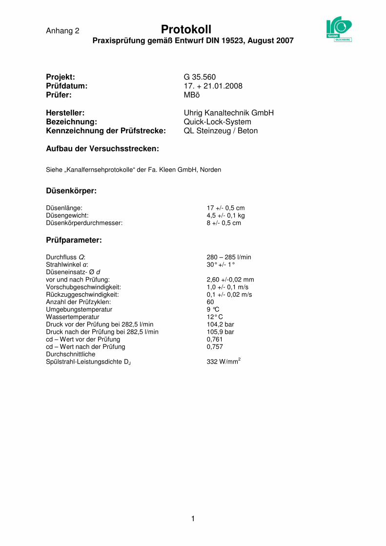
Anhang 2 Protokoll Praxisprüfung gemäß Entwurf DIN 19523, August 2007
1
Projekt: G 35.560 Prüfdatum: 17. + 21.01.2008 Prüfer: MBö Hersteller: Uhrig Kanaltechnik GmbH Bezeichnung: Quick-Lock-System Kennzeichnung der Prüfstrecke: QL Steinzeug / Beton Aufbau der Versuchsstrecken:
Siehe „Kanalfernsehprotokolle“ der Fa. Kleen GmbH, Norden
Düsenkörper: Düsenlänge: 17 +/- 0,5 cm Düsengewicht: 4,5 +/- 0,1 kg Düsenkörperdurchmesser: 8 +/- 0,5 cm
Prüfparameter: Durchfluss Q: 280 – 285 l/min Strahlwinkel α: 30° +/- 1° Düseneinsatz- Ø d
vor und nach Prüfung: 2,60 +/-0,02 mm
Vorschubgeschwindigkeit: 1,0 +/- 0,1 m/s Rückzuggeschwindigkeit: 0,1 +/- 0,02 m/s Anzahl der Prüfzyklen: 60 Umgebungstemperatur 9 °C Wassertemperatur 12° C Druck vor der Prüfung bei 282,5 l/min 104,2 bar Druck nach der Prüfung bei 282,5 l/min 105,9 bar cd – Wert vor der Prüfung 0,761 cd – Wert nach der Prüfung 0,757 Durchschnittliche Spülstrahl-Leistungsdichte DJ 332 W/mm
2

Anhang 2 Protokoll Praxisprüfung gemäß Entwurf DIN 19523, August 2007
2
Ergebnisse
Schadensdokumentation: Oberflächenbeschaffenheit der Manschetten vor der Prüfung
- Glatt, keine Auffälligkeiten
Oberflächenbeschaffenheit der Manschetten nach der Prüfung
- Die Innenoberfläche der Manschetten weist nach der Prüfung im Sohlbereich Schlauchabriebspuren auf.
- Zwei Manschetten im Steinzeugrohr weisen nach der Prüfung am Rand leichte Verformungen infolge mechanischen Düsenwiderstandes auf.

Anhang 2 Protokoll Praxisprüfung gemäß Entwurf DIN 19523, August 2007
3
Fotodokumentation
Abbildung 1: Schlauchabrieb im Sohlbereich nach der Prüfung

Anhang 2 Protokoll Praxisprüfung gemäß Entwurf DIN 19523, August 2007
4
Abbildung 2: Deformation des Manschettenrandes nach der Prüfung