report env. fatigue - department of energy report env fatigue.pdfpublished nureg-1801, “generic...
TRANSCRIPT

ANL-‐LWRS-‐47
Report on Assessment of Environmentally-‐Assisted Fatigue for LWR Extended Service Conditions
Nuclear Engineering Division

About Argonne National Laboratory Argonne is a U.S. Department of Energy laboratory managed by UChicago Argonne, LLC under contract DE-‐AC02-‐06CH11357. The Laboratory’s main facility is outside Chicago, at 9700 South Cass Avenue, Argonne, Illinois 60439. For information about Argonne, see http://www.anl.gov.
Disclaimer This report was prepared as an account of work sponsored by an agency of the United States Government. Neither the United States Government nor any agency thereof, nor UChicago Argonne, LLC, nor any of their employees or officers, makes any warranty, express or implied, or assumes any legal liability or responsibility for the accuracy, completeness, or usefulness of any information, apparatus, product, or process disclosed, or represents that its use would not infringe privately owned rights. Reference herein to any specific commercial product, process, or service by trade name, trademark, manufacturer, or otherwise, does not necessarily constitute or imply its endorsement, recommendation, or favoring by the United States Government or any agency thereof. The views and opinions of document authors expressed herein do not necessarily state or reflect those of the United States Government or any agency thereof, Argonne National Laboratory, or UChicago Argonne, LLC.

ANL-‐LWRS-‐47
Report on Assessment of Environmentally-‐Assisted Fatigue for LWR Extended Service Conditions
Saurin Majumdar and Ken Natesan Nuclear Engineering Division Argonne National Laboratory September 2011


Report on Assessment of Environmentally-‐Assisted Fatigue for LWR Extended Service Conditions September 2011
ANL-‐LWRS-‐47
i
ABSTRACT
This report provides an update on the assessment of environmentally-assisted fatigue for light water reactor (LWR) extended service conditions. The report is a deliverable in FY11 under the work package for LWRS under the Advanced Reactor Concepts.
Most of the current fleet of aging LWRs were designed using the 1970s version of the ASME Boiler and Pressure Vessels Code, Section III, and are reaching their design lifetime of 30-40 yrs. For economic reasons, the utilities have great interest in extending the operating life of the plants via the Nuclear Regulatory Commission (NRC) licensing renewal application (LRA) process. Based on issues learned from the reviews of LRAs and public comments, NRC has published NUREG-1801, “Generic Aging Lessons Learned (GALL) Report”. The GALL Report lists generic aging management reviews (AMRs) of systems, structures, and components (SSCs) that may be in the scope of license renewal applications (LRAs) and identifies aging management programs (AMPs) that are determined to be acceptable to manage aging effects of SSCs in the scope of license renewal. One of the critical aging issues identified in the GALL report is environmental fatigue.
The ASME Boiler and Pressure Vessel Code Section III fatigue design curves, developed in the late 1960s and early 1970s, are based on tests conducted in laboratory air environments at ambient temperatures. In the Code, adjustments are made to strain and cyclic life to account for variations in material properties, surface finish, data scatter, and unknown effects. The Code does not explicitly account for potential degradation in the fatigue properties attributable to exposure to LWR coolant environments. Recent fatigue test data and analyses have demonstrated conclusively that LWR environments have a significant impact on the fatigue life of reactor structural materials. To address the environmental fatigue issue, NRC has issued Regulatory Guide 1.207 (DG-1144), “GUIDELINES FOR EVALUATING FATIGUE ANALYSES INCORPORATING THE LIFE REDUCTION OF METAL COMPONENTS DUE TO THE EFFECTS OF THE LIGHT-WATER REACTOR ENVIRONMENT FOR NEW REACTORS”.
The overall objective of the current LWRS project is to assess the current state of knowledge in environmentally assisted fatigue of materials in light water reactors under extended service conditions. The report highlights the issues concerning the long-term fatigue of materials in LWR environments, presents a brief review of laboratory and field observations, assesses the ASME Code requirements for the nuclear components, and recommends areas of research and development for improving the reliability of database that enable life prediction for LWR components.

Report on Assessment of Environmentally-‐Assisted Fatigue for LWR Extended Service Conditions September 2011
ANL-‐LWRS-‐47 ii

Report on Assessment of Environmentally-‐Assisted Fatigue for LWR Extended Service Conditions September 2011
ANL-‐LWRS-‐47
iii
TABLE OF CONTENTS
ABSTRACT ................................................................................................................................ i List of Figures ............................................................................................................................. v
Abbreviations ........................................................................................................................... vii Acknowledgements ................................................................................................................. viii
1 Introduction ............................................................................................................................ 1 2 ASME Fatigue Design Rules for Carbon and Stainless Steels .............................................. 1
3 Carbon and Low-Alloy Steel Fatigue in LWR Environment ................................................. 5 3.1 Experimental Data .......................................................................................................... 5 3.2 Critical Parameters .......................................................................................................... 6
3.2.1 Strain Rate ............................................................................................................ 6 3.2.2 Strain Amplitude .................................................................................................. 7 3.2.3 Temperature .......................................................................................................... 8 3.2.4 Dissolved Oxygen ................................................................................................ 8 3.2.5 Water Conductivity .............................................................................................. 9 3.2.6 Sulfur Content ...................................................................................................... 9 3.2.7 Tensile Hold Period ............................................................................................ 10 3.2.8 Flow Rate ........................................................................................................... 11 3.2.9 Surface Finish ..................................................................................................... 12
3.3 Fatigue Life Model ....................................................................................................... 13 4 Austenitic Stainless Steels in LWR Environment ................................................................ 14
4.1 Experimental Data ........................................................................................................ 14 4.2 Critical Parameters ........................................................................................................ 17
4.2.1 Strain Amplitude ................................................................................................ 17 4.2.2 Hold-Time Effect ............................................................................................... 18 4.2.3 Strain Rate .......................................................................................................... 18 4.2.4 Dissolved oxygen ............................................................................................... 19 4.2.5 Water Conductivity ............................................................................................ 20 4.2.6 Temperature ........................................................................................................ 20 4.2.7 Material Heat Treatment .................................................................................... 21 4.2.8 Flow Rate ........................................................................................................... 22 4.2.9 Surface Finish ..................................................................................................... 22
4.3 Fatigue Life Model ....................................................................................................... 23
5 Ni-Cr-Fe Alloys and Welds .................................................................................................. 24 5.1 Experimental Data ........................................................................................................ 24 5.2 Critical Parameters ........................................................................................................ 25 5.3 Fatigue Life Model ....................................................................................................... 27

Report on Assessment of Environmentally-‐Assisted Fatigue for LWR Extended Service Conditions September 2011
ANL-‐LWRS-‐47 iv
6 Summary and Conclusions ................................................................................................... 27 7 Recommendation for Future Research ................................................................................. 29
References ................................................................................................................................. 30

Report on Assessment of Environmentally-‐Assisted Fatigue for LWR Extended Service Conditions September 2011
ANL-‐LWRS-‐47
v
LIST OF FIGURES
Figure 1. Strain amplitude vs. fatigue life data for (a) A533–Gr B and (b) A106–Gr B steels in air and high–dissolved–oxygen water at 288°C (Ref. 5). .......................................... 5
Figure 2. Dependence of faitigue life of carbon and low-alloy steels on strain rate. 5, 18 .......... 6 Figure 3. (a) S–N curves of A533B steel in simulated BWR water and 288_C air and (b) strain-
rate dependence of fatigue life in simulated BWR water.66 ...................................... 7 Figure 4. The relationship between fatigue life and applied strain amplitude in high
temperature water. (a) DO =100 ppb, (b) DO =2,000 ppb.67 .................................... 7 Figure 5. Change in fatigue life of A333–Gr 6 carbon steel with temperature and DO. ............. 8 Figure 6. Dependence on DO of fatigue life of carbon steel in high-purity water. ..................... 9 Figure 7. Effect of strain rate on fatigue life of low–alloy steels with different S contents
(JNUFAD database and Ref. 5. ............................................................................... 10 Figure 8. Effect of strain rate on the fatigue life of A333–Gr 6 carbon steels with different S
contents. ................................................................................................................... 10 Figure 9. Effect of water flow rate on fatigue life of A333–Gr 6 carbon steel at 289°C and
strain amplitude and strain rates of (a) 0.3% and 0.01%/s and (b) 0.6% and 0.001%/s................................................................................................................... 11
Figure 10. Effect of flow rate on low–cycle fatigue of carbon steel tube bends in high–purity water at 240°C .72 RT = room temperature. ............................................................ 12
Figure 11. Effect of surface roughness on fatigue life of (a) A106–Gr B carbon steel and (b) A533 low– alloy steel in air and high–purity water at 289°C. ................................ 12
Figure 12. Strain amplitude vs. fatigue life data for (a) Type 304 and (b) Type 316NG SS in water at 288°C (JNUFAD and Refs. 8,39). ............................................................. 15
Figure 13. Higher–magnification photomicrographs of oxide films that formed on Type 316NG stainless steel in (a) simulated PWR water and (b) high–DO water. ....................... 16
Figure 14. Effects of environment on formation of fatigue cracks in Type 316NG SS in air and low–DO water at 288°C. Preoxidized specimens were exposed for 10 days at 288°C in water that contained either <5 ppb DO and ≈ 23 cm3 /kg dissolved H2 or ≈ 500 ppb DO and no dissolved H2 (Ref. 7). .................................................................... 16
Figure 15. Results of strain rate change tests on Type 316 SS in low–DO water at 325°C. Low strain rate was applied during only a fraction of tensile loading cycle. Fatigue life is plotted as a function of fraction of strain at high strain rate (Refs. 25,30). ............. 17
Figure 16. Fatigue life of Type 304 stainless steel tested in high–DO water at 260–288°C with trapezoidal or triangular waveform (Refs. 9,26). ..................................................... 18
Figure 17. Dependence of fatigue lives of austenitic stainless steels on strain rate in low–DO water. 8,39,41,69 ...................................................................................................... 19
Figure 18. Dependence of fatigue life of Types (a) 304 and (b) 316NG stainless steel on strain rate in high– and low–DO water at 288°C. 8,39,41 ................................................. 19
Figure 19. Effects of conductivity of water and soaking period on fatigue life of Type 304 SS in high–DO water.8,39 ............................................................................................. 20
Figure 20. Change in fatigue lives of austenitic stainless steels in low–DO water with temperature. 8,24-26,29,39-41 ................................................................................. 21

Report on Assessment of Environmentally-‐Assisted Fatigue for LWR Extended Service Conditions September 2011
ANL-‐LWRS-‐47 vi
Figure 21. The effect of material heat treatment on fatigue life of Type 304 stainless steel in air, BWR and PWR environments at 289°C, ≈ 0.38% strain amplitude, sawtooth waveform, and 0.004%/s tensile strain rate.41 ......................................................... 21
Figure 22. Effect of water flow rate on the fatigue life of austenitic SSs in high-purity water at 289°C.21 ................................................................................................................... 22
Figure 23. Effect of surface roughness on fatigue life of (a) Type 316NG and (b) Type 304 stainless steels in air and high–purity water at 289°C. ............................................ 23
Figure 24. Fatigue ε –N behavior for Alloy 600 and its weld alloys in simulated BWR water at ≈ 289°C.34 ............................................................................................................... 25
Figure 25. Fatigue ε –N behavior for Alloys 600 and 690 and their weld alloys in simulated PWR water at 315 or 325°C.34,85 .......................................................................... 25
Figure 26. Dependence of fatigue lives of Alloys 690 and 600 and their weld alloys in PWR water at 325°C and Alloy 600 in BWR water at 289°C. 34,85 ............................... 26

Report on Assessment of Environmentally-‐Assisted Fatigue for LWR Extended Service Conditions September 2011
ANL-‐LWRS-‐47
vii
ABBREVIATIONS
AMP Aging Management Program AMR Aging Management Review ANL Argonne National Laboratory ANN Artificial Neural Network ASME American Society of Mechanical Engineers AVT All Volatile Treatment BWR Boiling Water Reactor CGR Crack Growth Rate CUF Cumulative Usage Factor DO Dissolved Oxygen EAC Environmentally Assisted Cracking ECP Electrochemical Potential EPR Electrochemical Potentiodynamic Reactivation EPRI Electric Power Research Institute GALL Generic Aging Lessons Learned GE General Electric Co. IHI Ishikawajima-Harima Heavy Industries KWU Kraftwerk Union Laboratories LRA Licensing Renewal Application LWR Light Water Reactor MA Mill Annealed MEA Materials Engineering Associates MHI Mitsubishi Heavy Industries MPA Materialprufungsanstalt MSC Microstructurally Small Crack NRC Nuclear Regulatory Commission ORNL Oak Ridge National Laboratory PVRC Pressure Vessel Research Council PWR Pressurized Water Reactor RCS Reactor Coolant System RT Room Temperature SCC Stress Corrosion Cracking SICC Strain Induced Corrosion Cracking SS Stainless Steel SSC Systems, Structures, and Components UTS Ultimate Tensile Strength WRC Welding Research Council

Report on Assessment of Environmentally-‐Assisted Fatigue for LWR Extended Service Conditions September 2011
ANL-‐LWRS-‐47 viii
ACKNOWLEDGEMENTS
This report has relied extensively on NUREG/CR-6909 by O.K. Chopra, O.K. and W. J. Shack of Argonne National Laboratory, the NRC issued Regulatory Guide 1.207, and some of the EPRI/industry developed field experience.

1
1 Introduction
Section III, Subsection NB, of the ASME Boiler and Pressure Vessel Code contains rules for the design of Class 1 components of nuclear power plants. Figures I-9.1 through I-9.6 of Appendix I to Section III specify the Code design fatigue curves for applicable structural materials. However, Section III, Subsection NB-3121 of the Code states that the effects of the coolant environment on fatigue resistance of a material were not addressed in these design curves. Therefore, the effects of environment on the fatigue resistance of materials used in operating pressurized water reactor (PWR) and boiling water reactor (BWR) plants, whose primary-coolant pressure boundary components were designed in accordance with the Code, are uncertain.
The current Section–III design fatigue curves of the ASME Code were based primarily on strain–controlled fatigue tests of small polished specimens at room temperature in air. Best–fit curves to the experimental test data were first adjusted to account for the effects of mean stress and then lowered by a factor of 2 on stress and 20 on cycles (whichever was more conservative) to obtain the design fatigue curves. These factors are not safety margins but rather adjustment factors that must be applied to experimental data to obtain estimates of the lives of components. Recent data on strain vs. fatigue-life (ε–N) obtained in the U.S.1 and Japan2, 3 demonstrate that LWR environments can have potentially significant effects on the fatigue resistance of materials. Specimen lives obtained from tests in simulated LWR environments can be much shorter than those obtained from corresponding tests in air.
2 ASME Fatigue Design Rules for Carbon and Stainless Steels
The ASME Code fatigue evaluation procedures are described in NB-3200, “Design by Analysis,” and NB-3600, “Piping Design.” For each stress cycle or load set pair, an individual fatigue usage factor is determined by the ratio of the number of cycles anticipated during the lifetime of the component to the allowable cycles. Figures I–9.1 through I–9.6 of the mandatory Appendix I to Section III of the ASME Boiler and Pressure Vessel Code specify fatigue design curves that define the allowable number of cycles as a function of applied stress amplitude. The cumulative usage factor (CUF) is the sum of the individual usage factors, and ASME Code Section III requires that at each location the CUF, calculated on the basis of Miner’s rule (Linear Damage Rule), must not exceed 1.
The ASME Code fatigue design curves, given in Appendix I of Section III, are based on strain–controlled tests on small polished specimens at room temperature in air. The design curves have been developed from the best–fit curves to the experimental strain versus fatigue life (ε–N) data, which are expressed in terms of the Langer equation4 of the form
εa = A1 N( )−n1 + A2 (1)
where εa is the applied strain amplitude, N is the fatigue life, and A1, A2, and n1 are parameters of the model. Equation (1) may be written in terms of stress amplitude Sa instead of εa. The stress amplitude is the product of εa and elastic modulus E, i.e., Sa = E⋅εa (stress amplitude is

2
one-half the applied stress range). The current ASME Code best–fit or mean curve described in the Section III criteria document2 for various steels is given by
Sa =
E4 Nf
ln 100100− Af
⎛
⎝⎜⎞
⎠⎟+ Bf (2)
where E is the elastic modulus, Nf is the number of cycles to failure, and Af and Bf are constants related to reduction in area in a tensile test and endurance limit of the material at 107 cycles, respectively. The current Code mean curve for carbon steel is expressed as
Sa = 59,734 Nf( )−0.5+149.2 (3)
for low-alloy steels, as
Sa = 49,222 Nf( )−0.5+ 265.4 (4)
and for austenitic SSs, as
Sa = 58,020 Nf( )−0.5+ 299.9 (5)
Note that because most of the data used to develop the Code mean curve were obtained on specimens that were tested to failure, in the Section III criteria document, fatigue life is defined as cycles to failure. Accordingly, the ASME Code fatigue design curves are generally considered to represent allowable number of cycles to failure. However, in Appendix I to Section III of the Code the design curves are simply described as stress amplitude (Sa) vs. number of cycles (N).
In the fatigue tests performed during the last three decades, fatigue life is defined in terms of the number of cycles for tensile stress to decrease 25% from its peak or steady–state value. For typical cylindrical specimens used in these studies, this corresponds to the number of cycles needed to produce a ≈ 3–mm–deep crack in the test specimen. Thus, the fatigue life of a material is actually being described in terms of three parameters, viz., strain or stress, cycles, and crack depth. The best–fit curve to the existing fatigue ε–N data describes, for given strain or stress amplitude, the number of cycles needed to develop a 3–mm deep crack.
The Code fatigue design curves have been obtained from the best–fit (or mean–data) curves by first adjusting for the effects of mean stress using the modified Goodman relationship given by
S'
a = Sa
σu − σ y
σu −Sa
⎛
⎝⎜
⎞
⎠⎟ forSa < σ y , (6)
and
Sa
' = Sa for Sa > σ y , (7)

3
where S’a is the adjusted value of stress amplitude, and σy and σu are yield and ultimate strengths of the material, respectively. Equations (6) and (7) assume the maximum possible mean stress and typically givea conservative adjustment for mean stress. The fatigue design curves are then obtained by reducing the fatigue life at each point on the adjusted best-fit curve by a factor of 2 on strain (or stress) or 20 on cycles, whichever is more conservative.
The factors of 2 and 20 are not safety margins but rather adjustment factors that should be applied to the small–specimen data to obtain reasonable estimates of the lives of actual reactor components. These factors were intended to account for data scatter (including material variability) and differences in surface condition and size between the test specimens and actual components. Although the Section III criteria document states that these factors were intended to cover such effects as environment, the term “atmosphere” was intended to reflect the effects of an industrial atmosphere in comparison with an air-conditioned laboratory, not the effects of a specific coolant environment. Subsection NB–3121 of Section III of the Code explicitly notes that the data used to develop the fatigue design curves (Figs. I–9.1 through I–9.6 of Appendix I to Section III) did not include tests in the presence of corrosive environments that might accelerate fatigue failure. Article B–2131 in Appendix B to Section III states that the owner’s design specifications should provide information about any reduction to fatigue design curves that is necessitated by environmental conditions.
Existing fatigue ε–N data illustrate potentially significant effects of light water reactor (LWR) coolant environments on the fatigue resistance of carbon and low–alloy steels and wrought and cast austenitic SSs.5-44 Laboratory data indicate that under certain reactor operating conditions, fatigue lives of carbon and low–alloy steels can be a factor of 17 lower in the coolant environment than in air. Therefore, the margins in the ASME Code may be less conservative than originally intended. The fatigue ε–N data are consistent with the much larger database on enhancement of crack growth rates (CGRs) in these materials in simulated LWR environments. The key parameters that influence fatigue life in these environments, e.g., temperature, dissolved–oxygen (DO) level in water, strain rate, strain (or stress) amplitude, and, for carbon and low–alloy steels, S content of the steel, have been identified. Also, the range of the values of these parameters within which environmental effects are significant has been clearly defined. If these critical loading and environmental conditions exist during reactor operation, then environmental effects will be significant and need to be included in the ASME Code fatigue evaluations. Experience with nuclear power plants worldwide indicates that the critical range of loading and environmental conditions that leads to environmental effects on fatigue crack initiation can occur during plant operation.5-44
Many failures of reactor components have been attributed to fatigue; examples include piping, nozzles, valves, and pumps.45-52 The mechanism of cracking in feedwater nozzles and piping has been attributed to corrosion fatigue or strain–induced corrosion cracking (SICC).53-55 A review of significant occurrences of corrosion fatigue damage and failures in various nuclear power plant systems has been presented in an Electric Power Research Institute (EPRI) report.56 In piping components, several failures were associated with thermal loading due to thermal stratification and striping. Thermal stratification is caused by the injection of low–flow, relatively cold feedwater during plant startup, hot standby, or variations below 20% of full power, whereas thermal striping is caused by rapid, localized fluctuations of the interface between hot and cold feedwater. Cracking has also occurred in nonisolable piping connected to a

4
PWR reactor coolant system (RCS). In most cases, thermal cycling was caused by interaction of hot RCS fluid from turbulent penetration at the top of the pipe, and cold valve leakage fluid that had stratified at the bottom of the pipe. Lenz et al.54 have shown that in feedwater lines, strain rates are 10–3 – 10–5 %/s due to thermal stratification and 10–1 %/s due to thermal shock. They also have reported that thermal stratification is the primary cause of crack initiation due to SICC. Full–scale mock-up tests to generate thermal stratification in a pipe in a laboratory have confirmed the applicability of laboratory data to component behavior.57, 58 A study conducted on stainless steel (SS) pipe bend specimens in simulated PWR primary water at 240°C concluded that reactor coolant environment can have a significant effect on the fatigue life of stainless steels.59 Relative to the fatigue life in an inert environment, life in the PWR environment at a strain amplitude of 0.52% was decreased by factor of 5.8 and 2.8 at strain rates of 0.0005%/s and 0.01%/s, respectively. These values show excellent agreement with the values predicted from the correlations presented in Ref. 1.
Thermal loading due to flow stratification or mixing was not included in the original design basis analyses. Regulatory evaluation has indicated that thermal–stratification cycling can occur in all PWR surge lines.60 In PWRs, the pressurizer water is heated to ≈227°C. The hot water, flowing at a very low rate from the pressurizer through the surge line to the hot–leg piping, rides on a cooler water layer. The thermal gradients between the upper and lower parts of the pipe can be as high as 149°C.
Two approaches have been proposed for incorporating the environmental effects into ASME Section III fatigue evaluations for primary pressure boundary components in operating nuclear power plants: (a) develop new fatigue design curves for LWR applications, or (b) use an environmental fatigue correction factor to account for the effects of the coolant environment.
In the first approach, following the same procedures used to develop the current fatigue design curves of the ASME Code, environmentally adjusted fatigue design curves are developed from fits to experimental data obtained in LWR environments. Interim fatigue design curves that address environmental effects on the fatigue life of carbon and low–alloy steels and austenitic SSs were first proposed by Majumdar et al.61 Fatigue design curves based on a more rigorous statistical analysis of experimental data were developed by Keisler et al.62 These design curves have subsequently been revised on the basis of updated ANL models.5,7,39,40 However, because, in LWR environments, the fatigue life of carbon and low–alloy steels, nickel-chromium-iron (Ni-Cr-Fe) alloys, and austenitic SSs depends on several loading and environmental parameters, such an approach would require developing several design curves to cover all possible conditions encountered during plant operation. Defining the number of these design curves or the loading and environmental conditions for the curves is not easy.
The second approach, proposed by Higuchi and Iida14, considers the effects of reactor coolant environments on fatigue life in terms of an environmental fatigue correction factor, Fen, which is the ratio of fatigue life in air at room temperature to that in water under reactor operating conditions. To incorporate environmental effects into fatigue evaluations, the fatigue usage factor for a specific stress cycle or load set pair, based on the ASME Code design curves, is multiplied by the environmental fatigue correction factor. Specific expressions for Fen, based on the Argonne National Laboratory (ANL) fatigue life models, have been developed.40 Such an approach is relatively simple and was recommended in Ref. 1.

5
3 Carbon and Low-‐Alloy Steel Fatigue in LWR Environment
3.1 Experimental Data Fatigue ε–N data on carbon and low–alloy steels in air and high–DO water at 288°C are
shown in Fig.1. The curves based on the ANL models (Eqs. (8) - (13) in Section 3.3) are also included in the figures. The fatigue data in LWR environments indicate a significant decrease in fatigue life of carbon and low–alloy steels when four key threshold conditions are satisfied simultaneously, viz., applied strain range, service temperature, and DO in the water are above a minimum threshold level, and the loading strain rate is below a threshold value. The S content of the steel is also an important parameter for environmental effects on fatigue life. Although the microstructures and cyclic–hardening behavior of carbon steels and low–alloy steels are significantly different, environmental degradation of fatigue life of these steels is identical. For both steels, environmental effects on fatigue life are moderate (i.e., it is a factor of ≈2 lower) if any one of the key threshold conditions is not satisfied.
(a) (b)
Figure 1. Strain amplitude vs. fatigue life data for (a) A533–Gr B and (b) A106–Gr B steels in air and high–dissolved–oxygen water at 288°C (Ref. 5).
The existing fatigue data indicate that a slow strain rate applied during the tensile–loading cycle is primarily responsible for environmentally assisted reduction in fatigue life of these steels.5 The mechanism of environmentally assisted reduction in fatigue life of carbon and low-alloy steels has been termed strain–induced corrosion cracking (SICC).47,54,55 The environmental effects on the fatigue life of carbon and low-alloy steels are consistent with the slip oxidation/dissolution mechanism for crack propagation.63,64 A critical concentration of sulfide (S2-) or hydrosulfide (HS-) ions, which is produced by the dissolution of sulfide inclusions in the steel, is required at the crack tip for environmental effects to occur. The requirements of this mechanism are that a protective oxide film is thermodynamically stable to ensure that the crack will propagate with a high aspect ratio without degrading into a blunt pit, and that a strain increment occurs to rupture that oxide film and thereby expose the underlying matrix to the environment. Once the passive oxide film is ruptured, crack extension is controlled by dissolution of freshly exposed surface and by the oxidation characteristics. The effect of the environment increases with decreasing strain rate. The mechanism assumes that environmental

6
effects do not occur during the compressive load cycle, because during that period water does not have access to the crack tip.
A model for the initiation or cessation of environmentally assisted cracking (EAC) of these steels in low-DO PWR environments has also been proposed.65 Initiation of EAC requires a critical concentration of sulfide ions at the crack tip, which is supplied with the sulfide ions as the advancing crack intersects the sulfide inclusions, and the inclusions dissolve in the high-temperature water. Sulfide ions are removed from the crack tip by one or more of the following processes: (a) diffusion due to the concentration gradient, (b) ion transport due to differences in the electrochemical potential (ECP), and (c) fluid flow induced within the crack due to flow of coolant outside the crack. Thus, environmentally enhanced CGRs are controlled by the synergistic effects of S content, environmental conditions, and flow rate. The EAC initiation/cessation model has been used to determine the minimum crack extension and CGRs that are required to maintain the critical sulfide ion concentration at the crack tip and sustained environmental enhancement of growth rates.
3.2 Critical Parameters
3.2.1 Strain Rate When all threshold conditions are satisfied, the fatigue life of carbon and low-alloy steels
decreases logarithmically with decreasing strain rate below 1%/s. The fatigue lives of A106–Gr B carbon steel and A533–Gr B low–alloy steel5, 18 are plotted as a function of strain rate in Fig. 12. Only a moderate decrease in fatigue life is observed in simulated (low–DO) PWR water, e.g., at DO levels of ≤0.05 ppm. For the heats of A106–Gr B carbon steel and A533–Gr B low–alloy steel, the effect of strain rate on fatigue life saturates at ≈0.001%/s strain rate.
(a) (b)
Figure 2. Dependence of faitigue life of carbon and low-alloy steels on strain rate. 5, 18
The strain-rate dependence of low cycle fatigue behavior of A533B low-alloy steel was investigated in a simulated BWR environment by Wu and Katada.66 Fatigue resistance of the steel was found to be closely dependent on cyclic strain rate in high-temperature water (Fig. 3). A tortuous cracking morphology was dominant at high strain rate. An entirely straight cracking morphology, however, became dominant at low strain rate. The above cracking behavior in

7
simulated BWR water was attributed to a strain-rate-induced change in the dominant EAC mechanism from hydrogen-induced cracking to film-rupture/slip-dissolution-controlled cracking.
(a) (b)
Figure 3. (a) S–N curves of A533B steel in simulated BWR water and 288_C air and (b) strain-rate dependence of fatigue life in simulated BWR water.66
3.2.2 Strain Amplitude Low cycle fatigue (LCF) behavior of an A533B-type low-alloy pressure vessel steel was
investigated by Wu and Katada67 in 200° C and 288° C water. Major attention was paid to the role of dynamic strain aging (DSA) on corrosion fatigue behavior of the steel. The study found that, under a low-DO condition (100 ppb), the LCF resistance of the steel at a high strain rate (0.1% S-1) in 200° C water was lower than that in 288° C water, while the LCF resistance at the low strain rate (0.001% S-1) in 200° C water was better than that in 288° C water, especially under a high strain amplitude condition (Fig. 4a).
(a) (b)
Figure 4. The relationship between fatigue life and applied strain amplitude in high temperature water. (a) DO =100 ppb, (b) DO =2,000 ppb.67
A minimum threshold strain range is required for environmentally assisted decrease in fatigue life, i.e., the LWR coolant environments have no effect on the fatigue life of these steels

8
at strain ranges below the threshold value. The fatigue lives of A533–Gr B and A106–Gr B steels in high–DO water at 288°C and various strain rates5 are shown in Fig.1. Fatigue tests at low strain amplitudes are rather limited. Because environmental effects on fatigue life increase with decreasing strain rate, fatigue tests at low strain amplitudes and strain rates that would result in significant environmental effects are restrictively time consuming. For the limited data that are available, the threshold strain amplitude (one-half the threshold strain range) appears to be slightly above the fatigue limit of these steels.
Exploratory fatigue tests with changing strain rate were conducted to determine the threshold strain range beyond which environmental effects are significant during a fatigue cycle.5 The threshold strain range for these steels were reported to be 0.32–0.36%.
3.2.3 Temperature The change in fatigue life of two heats of A333–Gr 6 carbon steel with test temperature at
different levels of DO is shown in Fig. 5.13,14,17 Other parameters, e.g., strain amplitude and strain rate, were kept constant; the applied strain amplitude was above and strain rate was below the critical threshold. In air, the two heats have a fatigue life of ≈ 3300 cycles. The results indicate a threshold temperature of 150°C, above which environment decreases fatigue life if DO in water is also above the critical level. In the temperature range of 150–320°C, the logarithm of fatigue life decreases linearly with temperature; the decrease in life is greater at high temperatures and DO levels. Only a moderate decrease in fatigue life is observed in water at temperatures below the threshold value of 150°C or at DO levels ≤ 0.05 ppm. Under these conditions, fatigue life in water is a factor of ≈ 2 lower than in air; Fig. 5 shows an average life of ≈ 2000 cycles for the heat with 0.015 wt.% S, and ≈ 1200 cycles for the 0.012 wt.% S steel.
(a) (b)
Figure 5. Change in fatigue life of A333–Gr 6 carbon steel with temperature and DO.
3.2.4 Dissolved Oxygen
The fatigue life dependence of carbon steel on DO content in water is shown in Fig. 6.13,14,17 The test temperature, applied strain amplitude, and S content in steel were above, and strain rate was below, the critical threshold value. The results indicate a minimum DO level of 0.04 ppm above which environment decreases the fatigue life of the steel. The effect of DO content on

9
fatigue life saturates at 0.5 ppm, i.e., increases in DO levels above 0.5 ppm do not cause further decreases in life. In Fig. 6, for DO levels between 0.04 and 0.5 ppm, fatigue life appears to decrease logarithmically with DO. Estimates of fatigue life from a trained ANN also show a similar effect of DO on the fatigue life of carbon steels and low–alloy steels.
(a) (b)
Figure 6. Dependence on DO of fatigue life of carbon steel in high-purity water.
Environmental effects on the fatigue life of carbon and low-alloy steels are minimal at DO levels below 0.04 ppm, i.e., in low-DO PWR or hydrogen–chemistry BWR environments. Environmental effects on fatigue life are expected to be insignificant in low–DO environments.
3.2.5 Water Conductivity In most studies the DO level in water has generally been considered the key environmental
parameter that affects the fatigue life of materials in LWR environments. Studies on the effect of the concentration of anionic impurities in water (expressed as the overall conductivity of water), are somewhat limited. The limited data indicate that the fatigue life of WB36 low–alloy steel at 177°C in water with ≈8 ppm DO decreased by a factor of ≈6 when the conductivity of water was increased from 0.06 to 0.5 µS/cm.47,68 A similar behavior has also been observed in another study of the effect of conductivity on the initiation of short cracks.69
3.2.6 Sulfur Content The fatigue ε–N data for low–alloy steels also indicate a dependence of fatigue life on S
content. When all the threshold conditions are satisfied, environmental effects on the fatigue life increase with increased S content. The fatigue lives of A508–Cl 3 steel with 0.003 wt.% S and A533–Gr B steel with 0.010 wt.% S are plotted as a function of strain rate in Fig. 21. However, the available data sets are too sparse to establish a functional form for dependence of fatigue life on S content and to define either a threshold for S content below which environmental effects are unimportant or an upper limit above which the effect of S on fatigue life may saturate. A linear dependence of fatigue life on S content has been assumed in correlations for estimating fatigue life of carbon steels and low–alloy steels in LWR environments.5,71 The limited data suggest that environmental effects on fatigue life saturate at S contents above 0.015 wt.%.5

10
Figure 7. Effect of strain rate on fatigue life of low–alloy steels with different S contents (JNUFAD database and Ref. 5.
The existing fatigue ε-N data also indicate significant reductions in fatigue life of some heats of carbon steel with S levels as low as 0.002 wt.%. The fatigue lives of several heats of A333–Gr 6 carbon steel with S contents of 0.002–0.015 wt.% in high-DO water at 288°C and 0.6% strain amplitude are plotted as a function of strain rate in Fig. 8. 5 Environmental effects on the fatigue life of these steels seem to be independent of S content in the range of 0.002–0.015 wt.%. However, these tests were conducted in air-saturated water (≈8 ppm DO). The fatigue life of carbon steels seems to be relatively insensitive to S content in very high DO water, e.g., greater than 1 ppm DO; under these conditions, the effect of DO dominates fatigue life. In other words, the saturation DO level of 0.5 ppm most likely is for medium- and high-S steels (i.e., steels with ≥0.005 wt.% S); it may be higher for low-S steels.
Figure 8. Effect of strain rate on the fatigue life of A333–Gr 6 carbon steels with different S contents.
3.2.7 Tensile Hold Period Fatigue tests conducted using trapezoidal waveforms indicate that a hold period at peak
tensile strain decreases the fatigue life of carbon steels in high–DO water at 289°C.5,19 However, a detailed examination of the data indicated that these results are either due to
11
limitations of the test procedure or caused by a frequency effect. The existing data do not demonstrate that hold periods at peak tensile strain affect the fatigue life of carbon and low-alloy steels in LWR environments.
3.2.8 Flow Rate Nearly all of the fatigue ε–N data for LWR environments have been obtained at very low
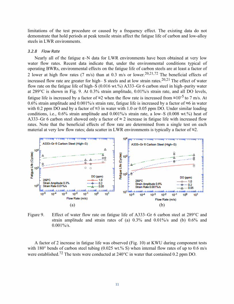
water flow rates. Recent data indicate that, under the environmental conditions typical of operating BWRs, environmental effects on the fatigue life of carbon steels are at least a factor of 2 lower at high flow rates (7 m/s) than at 0.3 m/s or lower.20,21,72 The beneficial effects of increased flow rate are greater for high– S steels and at low strain rates.20,21 The effect of water flow rate on the fatigue life of high–S (0.016 wt.%) A333–Gr 6 carbon steel in high–purity water at 289°C is shown in Fig. 9. At 0.3% strain amplitude, 0.01%/s strain rate, and all DO levels, fatigue life is increased by a factor of ≈2 when the flow rate is increased from ≈10-5 to 7 m/s. At 0.6% strain amplitude and 0.001%/s strain rate, fatigue life is increased by a factor of ≈6 in water with 0.2 ppm DO and by a factor of ≈3 in water with 1.0 or 0.05 ppm DO. Under similar loading conditions, i.e., 0.6% strain amplitude and 0.001%/s strain rate, a low–S (0.008 wt.%) heat of A333–Gr 6 carbon steel showed only a factor of ≈ 2 increase in fatigue life with increased flow rates. Note that the beneficial effects of flow rate are determined from a single test on each material at very low flow rates; data scatter in LWR environments is typically a factor of ≈2.
(a) (b)
Figure 9. Effect of water flow rate on fatigue life of A333–Gr 6 carbon steel at 289°C and strain amplitude and strain rates of (a) 0.3% and 0.01%/s and (b) 0.6% and 0.001%/s.
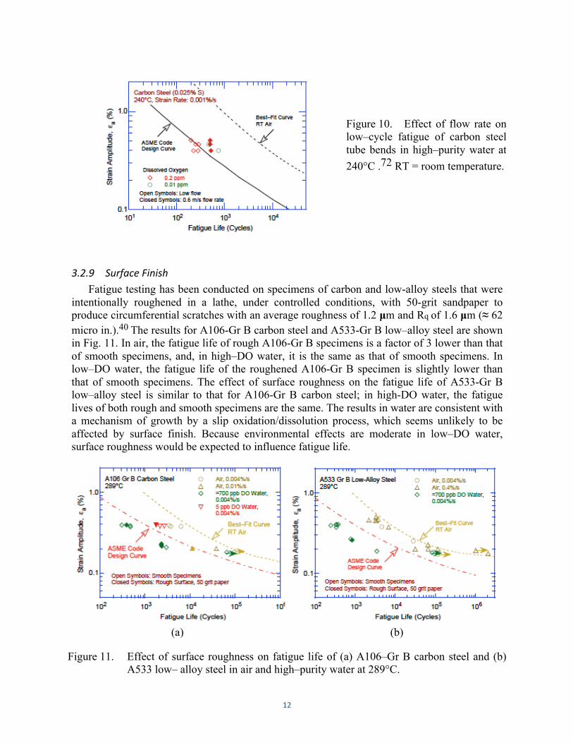
A factor of 2 increase in fatigue life was observed (Fig. 10) at KWU during component tests
with 180° bends of carbon steel tubing (0.025 wt.% S) when internal flow rates of up to 0.6 m/s were established.72 The tests were conducted at 240°C in water that contained 0.2 ppm DO.
12
Figure 10. Effect of flow rate on low–cycle fatigue of carbon steel tube bends in high–purity water at 240°C .72 RT = room temperature.
3.2.9 Surface Finish Fatigue testing has been conducted on specimens of carbon and low-alloy steels that were
intentionally roughened in a lathe, under controlled conditions, with 50-grit sandpaper to produce circumferential scratches with an average roughness of 1.2 µm and Rq of 1.6 µm (≈ 62 micro in.).40 The results for A106-Gr B carbon steel and A533-Gr B low–alloy steel are shown in Fig. 11. In air, the fatigue life of rough A106-Gr B specimens is a factor of 3 lower than that of smooth specimens, and, in high–DO water, it is the same as that of smooth specimens. In low–DO water, the fatigue life of the roughened A106-Gr B specimen is slightly lower than that of smooth specimens. The effect of surface roughness on the fatigue life of A533-Gr B low–alloy steel is similar to that for A106-Gr B carbon steel; in high-DO water, the fatigue lives of both rough and smooth specimens are the same. The results in water are consistent with a mechanism of growth by a slip oxidation/dissolution process, which seems unlikely to be affected by surface finish. Because environmental effects are moderate in low–DO water, surface roughness would be expected to influence fatigue life.
(a) (b)
Figure 11. Effect of surface roughness on fatigue life of (a) A106–Gr B carbon steel and (b) A533 low– alloy steel in air and high–purity water at 289°C.

13
Test specimens of ASTM A533B were intentionally roughened with 1000, 500, 240, 120 and 40 grit grinding papers, respectively, to produce circumferential scratches to investigate the effects of surface finish of specimens on fatigue cracking behavior in high temperature water73
The test conditions were 0.001%S-1 and 0.1% S-1 strain rate, 0.3% to 0.75% strain amplitude, 561 K temperature and 8.0 MPa pressure. The water chemistry was 100 ppb dissolved oxygen concentration, 6.2 to 6.5 pH, and < 0.2 µS/cm conductivity. The influence of surface finish on fatigue resistance and cracking behavior of low-alloy RPV steel was strain-rate dependent. At slow strain rate, surface circumferential scratches promoted crack initiation and propagation. The fracture surface showed relatively flat and slight crack-arrest features. At fast strain rate, surface scratches also promoted crack initiation, but seemed not to dominate crack propagation. The results were rationalized by a strain-rate dependent EAC process, i.e., from hydrogen-induced cracking process at fast strain rate to film-rupture/ slip-dissolution cracking process at slow strain rate.
3.3 Fatigue Life Model Fatigue-life models for estimating the fatigue lives of carbon and low–alloy steels in LWR
environments based on the existing fatigue ε–N data have been developed at ANL.5,40 The effects of key parameters, such as temperature, strain rate, DO content in water, and S content in the steel, are included in the correlations; the effects of these and other parameters on the fatigue life are discussed below in detail. The functional forms for the effects of strain rate, temperature, DO level in water, and S content in the steel were based on the data trends. For both carbon and low-alloy steels, the model assumes threshold and saturation values of 1.0 and 0.001%/s, respectively, for strain rate; 0.001 and 0.015 wt.%, respectively, for S; and 0.04 and 0.5 ppm, respectively, for DO. It also considers a threshold value of 150°C for temperature.
The effects of reactor coolant environments on fatigue life have been expressed in terms of environmental fatigue correction factor, Fen, which is defined as the ratio of life in air at room temperature, NRTair, to that in water at the service temperature, Nwater.
Fen =
NRTair
Nwater
(8)
Originally, separate equations of Fens for carbon steels and low alloy steels were reported in Ref. 1. In the latest iteration,74 they have been merged into a single equation for both types of alloys.
Fen=exp[(0.00285-0.02972 )S*T*O*] for εa > 0.07%
Fen= 1 for εa ≤ 0.07% (9)
where S*, T*, O*, and ε* are transformed S content, temperature, DO level, and strain rate, respectively, defined as:
S* = 2.0 + 98 S (S ≤ 0.015 wt.%)
ε*

14
S* = 3.47 (S > 0.015 wt.%) (10)
T* = 0.395 (T ≤ 150°C)
T* = (T – 75)/190 (150 < T ≤ 325°C)
T* = 1.316 (T ≥ 325 °C) (11)
O* = 1.49 (DO ≤ 0.04 ppm)
O* = ln(DO/0.009) (0.04 ppm < DO ≤ 0.5 ppm)
O* = 4.02 (DO > 0.5 ppm) (12)
ε*= 0 ( ε > 2.2%/s)
ε* = ln( ε /2.2) (0.001 ≤ ε ≤ 2.2 %/s)
ε* = ln(0.001/2.2) ( ε < 0.001%/s). (13)
4 Austenitic Stainless Steels in LWR Environment
The relevant fatigue ε–N data for austenitic SSs in air include the data compiled by Jaske and O'Donnell75 for developing fatigue design criteria for pressure vessel alloys, the JNUFAD database from Japan, studies at EdF in France,76 and the results of Conway et al.77 and Keller.78 In water, the existing fatigue ε–N data include the tests performed by GE in a test loop at the Dresden 1 reactor;9-12 the JNUFAD data base; studies at MHI, IHI, and Hitachi in Japan;19-31 the work at ANL;7,8,37-41, the studies sponsored by Electricite de France (EdF).68,69, and the study conducted by Seifert, Ritter, and Leber at the Paul Scherer Institute70 Nearly 60% of the tests in air were conducted at room temperature, 20% at 250–325°C, and 20% at 350–450°C. Nearly 90% of the tests in water were conducted at temperatures between 260 and 325°C; the remainder were at lower temperatures. The data on Type 316NG in water have been obtained primarily at DO levels ≥0.2 ppm, and those on Type 316 SS, at ≤0.005 ppm DO; half of the tests on Type 304 SS are at low–DO and the remaining at high–DO levels.
4.1 Experimental Data The fatigue lives of austenitic SSs are decreased in LWR environments; the fatigue ε-N data
for Types 304 and 316NG stainless steels in water at 288°C are shown in Fig. 12. The ε–N curves based on the ANL model are also included in the figures. The fatigue life is decreased significantly when three threshold conditions are satisfied simultaneously, viz., applied strain range and service temperature are above a minimum threshold level, and the loading strain rate is below a threshold value. Also, the DO level in the water and, possibly, the composition and heat treatment of the steel are important parameters for environmental effects on fatigue life. For some steels, fatigue life is longer in high-DO water than in low-DO PWR environments. Although, in air, the fatigue life of Type 316NG SS is slightly longer than that of Types 304 and 316 SS, the effects of LWR environments are comparable for wrought Types 304, 316, and

15
316NG stainless steels. Also, limited data indicate that the fatigue life of cast austenitic stainless steels in both low-DO and high-DO environments is comparable to that of wrought stainless steels in low-DO environment.
The existing fatigue data indicate that a slow strain rate applied during the tensile-loading cycle (i.e., up–ramp with increasing strain) is primarily responsible for the environmentally assisted reduction in fatigue life. Slow rates applied during both tensile- and compressive-loading cycles (i.e., up- and down-ramps) do not further decrease fatigue life compared with that observed for tests with only a slow tensile-loading cycle (Fig. 12b). Consequently, loading and environmental conditions during the tensile-loading cycle (strain rate, temperature, and DO level) are important for environmentally assisted reduction of the fatigue lives of these steels.
(a) (b)
Figure 12. Strain amplitude vs. fatigue life data for (a) Type 304 and (b) Type 316NG SS in water at 288°C (JNUFAD and Refs. 8,39).
For austenitic SSs, lower fatigue lives in low-DO water than in high-DO water are difficult to reconcile in terms of the slip oxidation/dissolution mechanism, which assumes that crack growth rates increase with increasing DO in the water. The characteristics of the surface oxide films that form on austenitic SSs in LWR coolant environments can influence the mechanism and kinetics of corrosion processes and thereby influence the initiation stage, i.e., the growth of MSCs. Also, the reduction of fatigue life in high–temperature water has often been attributed to the presence of surface micro-pits that may act as stress raisers and provide preferred sites for the formation of fatigue cracks. Photomicrographs of the gauge surfaces of Type 316NG specimens tested in simulated PWR water and high–DO water are shown in Fig. 13. Austenitic SSs exposed to LWR environments develop an oxide film that consists of two layers: a fine–grained, tightly-adherent, chromium-rich inner layer, and a crystalline, nickel-rich outer layer composed of large and intermediate-size particles. The inner layer forms by solid–state growth, whereas the crystalline outer layer forms by precipitation or deposition from the solution. The structure and composition of the inner and outer layers and their variation with the water chemistry have been identified.79,80

16
Figure 13. Higher–magnification photomicrographs of oxide films that formed on Type 316NG stainless steel in (a) simulated PWR water and (b) high-DO water.
Experimental data indicate that surface micro-pits or minor differences in the composition or structure of the surface oxide film have no effect on the formation of fatigue cracks. Fatigue tests were conducted on Type 316NG (Heat P91576) SS specimens that were pre-exposed to either low-DO or high-DO water and then tested in air or water environments. The results of these tests, as well as data obtained earlier on this heat and Heat D432804 of Type 316NG SS in air and low–DO water at 288°C, are plotted in Fig. 41. The fatigue life of a specimen pre-oxidized in high–DO water and then tested in low–DO water is identical to that of specimens tested without pre-oxidation. Also, fatigue lives of specimens pre-oxidized at 288°C in low–DO water and then tested in air are identical to those of unoxidized specimens (Fig. 14). If micro-pits were responsible for the reduction in life, the pre-exposed specimens should show a decrease in life. Also, the fatigue limit of these steels should be lower in water than in air, but the data indicate that this limit is the same in water and air environments. Metallographic examination of the test specimens indicated that environmentally assisted reduction in fatigue lives of austenitic stainless steels most likely is not caused by slip oxidation/dissolution but some other process, such as hydrogen-induced cracking.8,37,38
Figure 14. Effects of environment on formation of fatigue cracks in Type 316NG SS in air and low–DO water at 288°C. Preoxidized specimens were exposed for 10 days at 288°C in water that contained either <5 ppb DO and ≈ 23 cm3 /kg dissolved H2 or ≈ 500 ppb DO and no dissolved H2 (Ref. 7).

17
The corrosion fatigue initiation and short crack growth behavior of different low-carbon and stabilized austenitic stainless steels was characterized under simulated boiling water reactor hydrogen water chemistry and primary pressurized water reactor conditions by Seifert et al.70 using cyclic fatigue tests with sharply notched fracture mechanics specimens in the temperature range from 70 to 320°C. They reported a relevant environmental reduction of fatigue initiation life for the combination of temperatures ≥ 100°C, notch strain rates ≤ 0.1%/s and notch strain amplitudes ≥ 0.3%. If these three threshold conditions were simultaneously satisfied, the environmental enhancement increased with decreasing strain rate and increasing temperature. Material and water chemistry parameters usually only had a minor effect.
4.2 Critical Parameters
4.2.1 Strain Amplitude As in the case of the carbon and low-alloy steels, a minimum threshold strain range is
required for the environmentally induced decrease in fatigue lives of stainless steels to occur. Exploratory fatigue tests have also been conducted on austenitic stainless steels to determine the threshold strain range beyond which environmental effects are significant during a fatigue cycle.25,30 The tests were performed with waveforms in which the slow strain rate is applied during only a fraction of the tensile loading cycle. The results indicate that a minimum threshold strain is required for an environmentally assisted decrease in the fatigue lives of SSs (Fig. 15). The threshold strain range Δεth appears to be independent of material type (weld or base metal) and temperature in the range of 250–325°C, but it tends to decrease as the strain range is decreased.25,30 The threshold strain range may be expressed in terms of the applied strain range Δε by the equation
Δε th / Δε = – 0.22 Δε + 0.65. (14)
The results suggest that Δεth is related to the elastic strain range of the test and does not correspond to the strain at which the crack closes.
Figure 15. Results of strain rate change tests on Type 316 SS in low–DO water at 325°C. Low strain rate was applied during only a fraction of tensile loading cycle. Fatigue life is plotted as a function of fraction of strain at high strain rate (Refs. 25,30).

18
4.2.2 Hold-‐Time Effect Environmental effects on fatigue life occur primarily during the tensile–loading cycle and at
strain levels greater than the threshold value. Information on the effect of hold periods on the fatigue life of austenitic SSs in water is very limited. In high–DO water, the fatigue lives of Type 304 SS tested with a trapezoidal waveform (i.e., hold periods at peak tensile and compressive strain)8 are comparable to those tested with a triangular waveform,26 as shown in Fig. 16. As discussed in Section 3.2.7, a similar behavior has been observed for carbon and low–alloy steels: the data show little or no effect of hold periods on fatigue lives of the steels in high–DO water.
Figure 16. Fatigue life of Type 304 stainless steel tested in high-DO water at 260-288°C with trapezoidal or triangular waveform (Refs. 9,26).
The existing data do not demonstrate that hold periods at peak tensile strain affect the fatigue life of austenitic stainless steels in LWR environments.
4.2.3 Strain Rate The fatigue life of Types 304L and 316 SSs in low-DO water is plotted as a function of
tensile strain rate in Fig. 17. In low–DO PWR environment, the fatigue life of austenitic SSs decreases with decreasing strain rate below ≈0.4%/s; the effect of environment on fatigue life saturates at ≈0.0004%/s (Fig. 17).8,1922-26,29,30,39-41Only a moderate decrease in life is observed at strain rates greater than 0.4%/s. A decrease in strain rate from 0.4 to 0.0004%/s decreases the fatigue life by a factor of ≈ 10.
In high-DO water, the effect of strain rate may be less pronounced than in low-DO water (Fig. 18). For example, for Heat 30956 of Type 304 SS, strain rate has no effect on fatigue life in high–DO water, whereas life decreases linearly with strain rate in low-DO water (Fig. 18a). For Heat D432804 of Type 316NG, some effect of strain rate is observed in high-DO water, although it is smaller than that in low-DO water (Fig. 18b).

19
(a) (b)
Figure 17. Dependence of fatigue lives of austenitic stainless steels on strain rate in low–DO water. 8,39,41,69
(a) (b)
Figure 18. Dependence of fatigue life of Types (a) 304 and (b) 316NG stainless steel on strain rate in high-and low-DO water at 288°C. 8,39,41
4.2.4 Dissolved oxygen In contrast to the behavior of carbon and low-alloy steels, the fatigue lives of austenitic
stainless steels decrease significantly in low–DO (i.e., <0.05 ppm DO) water. In low-DO water, the fatigue life is not influenced by the composition or heat treatment condition of the steel. The fatigue life, however, continues to decrease with decreasing strain rate and increasing temperature. 8,19,24-26,29,30,39-41
In high-DO water, the fatigue lives of austenitic SSs are either comparable to24,29or, in some cases, higher8,39,41than those in low-DO water, i.e., for some SSs, environmental effects may be lower in high-DO than in low-DO water. The results presented in Figs. 18a and 18b indicate that,

20
in high–DO water, environmental effects on the fatigue lives of austenitic SSs are influenced by the composition and heat treatment of the steel. For example, for high-carbon Type 304 SS, environmental effects in high-DO water are insignificant for the mill–annealed (MA) material (Fig. 18a), whereas as discussed in Section 4.2.7, for sensitized material the effect of environment is the same in high- and low-DO water. For the low-C Type 316NG SS, some effect of strain rate is apparent in high-DO water, although it is smaller than that in low-DO water (Fig. 18b). The effect of material heat treatment on the fatigue life of Type 304 SS is discussed in Section 4.2.7; in high-DO water, material heat treatment affects the fatigue life of stainless steels.
4.2.5 Water Conductivity The studies at ANL indicate that, for fatigue tests in high-DO water, the conductivity of
water and the ECP of steel are important parameters that must be held constant.8,39,41 During laboratory tests, the time to reach stable environmental conditions depends on the autoclave volume, DO level, flow rate, etc. In the ANL test facility, fatigue tests on austenitic SSs in high-DO water required a soaking period of 5 - 6 days for the ECP of the steel to stabilize. The steel ECP increased from zero or a negative value to above 150 mV during this period. The results shown in Fig. 18a for MA Heat 30956 of Type 304 SS in high–DO water (filled circles) were obtained for specimens that were soaked for 5-6 days before the test. The same material tested in high-DO water after soaking for only 24 h showed a significant reduction in fatigue life, as indicated by Fig. 19.
The effect of the conductivity of water and the ECP of the steel on the fatigue life of austenitic SSs is shown in Fig. 19. In high–DO water, fatigue life is decreased by a factor of ≈ 2 when the conductivity of water is increased from ≈ 0.07 to 0.4 µS/cm. Note that environmental effects appear more significant for the specimens that were soaked for only 24 h. For these tests, the ECP of steel was initially very low and increased during the test.
Figure 19. Effects of conductivity of water and soaking period on fatigue life of Type 304 SS in high–DO water.8,39
4.2.6 Temperature The change in fatigue lives of austenitic SSs with test temperature at two strain amplitudes
and two strain rates is shown in Fig. 20. The results suggest a threshold temperature of 150°C, above which the environment decreases fatigue life in low-DO water if the strain rate is below the threshold of 0.4%/s. In the range of 150-325°C, the logarithm of fatigue life decreases

21
linearly with temperature. Only a moderate decrease in life occurs in water at temperatures below the threshold value of 150°C.
(a) (b)
Figure 20. Change in fatigue lives of austenitic stainless steels in low–DO water with temperature. 8,24-26,29,39-41
4.2.7 Material Heat Treatment Limited data indicate that, although heat treatment has little or no effect on the fatigue life of
austenitic SSs in low–DO and air environments, in a high-DO environment, fatigue life may be longer for nonsensitized or slightly sensitized SS.41 The effect of heat treatment on the fatigue life of Type 304 SS in air, BWR, and PWR environments is shown in Fig. 21. Fatigue life is plotted as a function of the EPR (electrochemical potentio-dynamic reactivation) value for the various material conditions. The results indicate that heat treatment has little or no effect on the fatigue life of Type 304 SS in air and PWR environments. In a BWR environment, fatigue life is lower for the sensitized SSs; fatigue life decreases with increasing EPR value.
Figure 21. The effect of material heat treatment on fatigue life of Type 304 stainless steel in air, BWR and PWR environments at 289°C, ≈ 0.38% strain amplitude, sawtooth waveform, and 0.004%/s tensile strain rate.41

22
These results are consistent with the data obtained at MHI on solution-annealed and sensitized Types 304 and 316 SS.22,26 In low-DO (<0.005 ppm) water at 325°C, a sensitization annealing had no effect on the fatigue lives of these steels. In high-DO (8 ppm) water at 300°C, the fatigue life of sensitized Type 304 SS was a factor of ≈ 2 lower than that of the solution-annealed steel. However, a sensitization anneal had little or no effect on the fatigue life of low-C Type 316NG SS in high-DO water at 288°C, and the lives of solution-annealed and sensitized Type 316NG SS were comparable.
4.2.8 Flow Rate Tests in both low-DO and high-DO environments indicate that increasing flow rate has no
effect or may have a detrimental effect on the fatigue life of austenitic SSs. Figure 22 shows the effect of water flow rate on the fatigue lives of Types 316NG and 304 SSs in high-purity water at 289°C. Under all test conditions, the fatigue lives of these steels are slightly lower at high flow rates than those at lower rates or semi-stagnant conditions.
Figure 22. Effect of water flow rate on the fatigue life of austenitic SSs in high-purity water at 289°C.21
Fatigue tests conducted on SS pipe bend specimens in simulated PWR primary water at 240°C also indicate that water flow rate has no effect on the fatigue lives of austenitic SSs. Increasing the flow rate from 0.005 m/s to 2.2 m/s had no effect on fatigue crack initiation in ≈ 26.5–mm diameter tube specimens. These results appear to be consistent with the notion that, in LWR environments, the mechanism of fatigue crack initiation in austenitic SSs may differ from that in carbon and low–alloy steels.
4.2.9 Surface Finish Fatigue tests have been conducted on Types 304 and 316NG SS specimens that were
intentionally roughened in a lathe, under controlled conditions, with 5-grit sandpaper to produce circumferential cracks with an average surface roughness of 1.2 µm. The results are shown in Figs. 23a and b, respectively, for Types 316NG and 304 SS. For both steels, the fatigue life of roughened specimens is lower than that of the smooth specimens in air and low-DO water environments. In high-DO water, the fatigue life of Heat P91576 of Type 316NG is the same for rough and smooth specimens.

23
(a) (b)
Figure 23. Effect of surface roughness on fatigue life of (a) Type 316NG and (b) Type 304 stainless steels in air and high–purity water at 289°C.
4.3 Fatigue Life Model In LWR environments, the fatigue life of austenitic SSs depends on strain rate, DO level, and
temperature. The functional forms for the effects of strain rate and temperature are based on the data trends. For both wrought and cast austenitic SSs, the model assumes saturation and threshold values of 10 and 0.0004%/s, respectively, for strain rate and a threshold value of 150°C for temperature. The influence of DO level on the fatigue life of austenitic stainless steel is not well understood. As discussed in Section 4.2.4, the fatigue lives of austenitic SSs are decreased significantly in low-DO water, whereas in high-DO water they are either comparable or, for some steels, higher than those in low-DO water. In high-DO water, the composition and heat treatment of the steel influence the magnitude of environmental effects on austenitic stainless steels. Until more data are available to clearly establish the effects of DO level on fatigue life, the effect of DO level on fatigue life is assumed to be the same in low-and high-DO water and for wrought and cast austenitic stainless steels.
The least-squares fit of the experimental data in water yields a steeper slope for the ε-N curve than the slope of the curve obtained in air.39.81 These results indicate that environmental effect may be more pronounced at low than at high strain amplitudes. The effects of reactor coolant environments on fatigue life have been expressed in terms of environmental fatigue correction factor, Fen, which is defined as the ratio of life in air at room temperature, NRTair, to that in water at the service temperature, Nwater.
Fen =
NRTair
Nwater
(15)
The original Fen equation for stainless steels, as reported in Ref. 1, was modified recently.74

24
Fen=exp[-T*O* ] for εa > 0.1%
Fen= 1 for εa ≤ 0.1% (16)
where T*, O*, and are transformed temperature, DO level, and strain rate, respectively, defined as:
T* = 0 (T ≤ 150°C)
T* = (T – 150)/190 (150 < T ≤ 325°C)
T* = 0.92 (T ≥ 325 °C) (17)
O* = 0.29 (DO ≤ 0.1 ppm)
O* = 0.14 (DO > 0.1 ppm) (18)
= 0 ( > 10%/s)
= ln( /10) (0.0004 ≤ ≤ 10 %/s)
= ln(0.0004/10) ( < 0.0004%/s). (19)
5 Ni-‐Cr-‐Fe Alloys and Welds The relevant fatigue ε–N data for Ni-Cr-Fe alloys and their welds in air and water
environments include the data compiled by Jaske and O’Donnell75 for developing fatigue design criteria for pressure vessel alloys; the JNUFAD database from Japan; studies at MHI, IHI, and Hitachi in Japan;34 studies at Knolls Atomic Power Laboratory;82,83 work sponsored by EPRI at Westinghouse Electric Corporation;84 the tests performed by GE in a test loop at the Dresden 1 reactor;9 and the results of Van Der Sluys et al.85 For Alloys 600 and 690, nearly 70% of the tests in air were conducted at room temperature and the remainder at 83–325°C. For Ni-Cr-Fe alloy welds (e.g., Alloys 82, 182, 132, and 152) nearly 85% of the tests in air were conducted at room temperature. In water, nearly 60% of the tests were conducted in simulated BWR environment (≈ 0.2 ppm DO) and 40% in PWR environment (< 0.01 ppm DO); tests in BWR water were performed at 288°C and in PWR water at 315 or 325°C. The existing fatigue data also include some tests in water with all volatile treatment (AVT) and at very high frequencies, e.g., 20 Hz to 40 kHz.75 As expected, environmental effects on fatigue life were not observed for these tests; the results in AVT water are not included in Ref. 1.
5.1 Experimental Data The fatigue lives of Ni-Cr-Fe alloys and their welds are also decreased in LWR
environments; the fatigue ε-N data for various Ni-Cr-Fe alloys in simulated BWR water at ≈ 289°C and PWR water at 315-325°C are shown in Figs. 24 and 25, respectively. The ε–N curves based on the ANL model for austenitic SSs (Eqs. (19)(15) - in Section 4.3) and the ASME Section III mean-data curve for austenitic SSs are also included in the figures. The results
ε*
ε*
ε* ε
ε* ε ε
ε* ε

25
indicate that environmental effects on the fatigue life of Ni-Cr-Fe alloys are strongly dependent on key parameters such as strain rate, temperature, and DO level in water. Similar to SSs, the effect of coolant environment on the fatigue life of Ni-Cr-Fe alloys is greater in the low–DO PWR environment than in the high–DO BWR environment. However, under similar loading and environmental conditions, the extent of the effects of environment is considerably less for the Ni-Cr- Fe alloys than for austenitic SSs. In general, environmental effects on fatigue life are the same for wrought and weld alloys.
(a) (b)
Figure 24. Fatigue ε-N behavior for Alloy 600 and its weld alloys in simulated BWR water at ≈ 289°C.34
(a) (b)
Figure 25. Fatigue ε –N behavior for Alloys 600 and 690 and their weld alloys in simulated PWR water at 315 or 325°C.34,85
5.2 Critical Parameters The existing fatigue ε-N data for Ni-Cr-Fe alloys in LWR environments are very limited; the
effects of key loading and environmental parameters (e.g., strain rate, temperature, and DO level)

26
on fatigue life of these alloys have been evaluated by Higuchi et al.34 The fatigue lives of Alloys 600 and 690 and their weld metals (e.g., Alloys 132 and 152) in simulated PWR and BWR water at different strain amplitudes are plotted as a function of strain rate in Fig. 26. The fatigue life of these alloys decreases logarithmically with decreasing strain rate. Although fatigue data at strain rates below 0.001%/s are not available, for Ni-Cr-Fe alloys, the effect of strain rate is assumed to be similar to that for austenitic SSs; the effect saturates at 0.0004%/s strain rate. Also, the threshold strain rate below which environmental effects are significant cannot be determined from the present data. Higuchi et al.34 have defined a threshold strain rate of 1.8%/s in high-DO BWR water and 26.1%/s in low-DO PWR water. As discussed in Section 6.2.3, an average threshold value of 5%/s provides good estimates of fatigue lives of Ni-Cr-Fe alloys in LWR environments.
The results also indicate that the effects of environment are greater in the low–DO PWR water than in high-DO BWR water. For example, a three orders of magnitude decrease in strain rate decreases the fatigue life of these alloys by a factor of ≈ 3 in PWR water and by ≈ 2 in BWR water.
The existing data are inadequate to determine accurately the functional form for the effect of temperature on fatigue life or to define the threshold strain amplitude below which environmental effects on fatigue life do not occur. In Ref. 1, such effects were assumed to be similar to those observed in austenitic SSs. It was also assumed that a slow strain rate applied during the tensile–loading cycle (i.e., up–ramp with increasing strain) is primarily responsible for the environmentally assisted reduction in fatigue life. Slow rates applied during both tensile– and compressive–loading cycles (i.e., up– and down–ramps) do not further decrease fatigue life compared with that observed for tests with only a slow tensile–loading cycle. Thus, loading and environmental conditions during the tensile–loading cycle are important for environmentally assisted reduction of the fatigue lives of Ni-Cr-Fe alloys.
(a) (b)
Figure 26. Dependence of fatigue lives of Alloys 690 and 600 and their weld alloys in PWR water at 325°C and Alloy 600 in BWR water at 289°C. 34,85

27
5.3 Fatigue Life Model The effects of reactor coolant environments on fatigue life of Ni-Cr-Fe alloys can also be
expressed in terms of a fatigue life correction factor Fen, which is defined as the ratio of life in air at room temperature to that in water at the service temperature (Eq. (15). The existing fatigue data are very limited to develop a fatigue life model for estimating the fatigue life of Ni-Cr-Fe alloys in LWR environments. However, as discussed above in Section 5.2, environmental effects for these alloys show the same trends as those observed for austenitic SSs. Thus, Fen for Ni-Cr-Fe alloys can be expressed as
Fen=exp(-T* ε*O*) (20)
The functional form of the transformed parameters were obtained from a best fit of the experimental data as follows:
T*=T/325 (T<325°C)
T*=1 (T>325°C) (21)
ε* = 0 ( ε > 5%/s)
ε*= ln( ε /5) (0.0004 ≤ ε ≤ 5%/s)
ε* = ln(0.0004/5) ( ε < 0.0004%/s) (22)
O*=0.09 (NWC BWR water)
O*=0.16 (PWR or HWC BWR water) (23)
The threshold strain amplitude value is assumed to be the same as that for austenitic SSs. The threshold strain amplitude is 0.10% (195 MPa stress amplitude) for Ni-Cr-Fe alloys.
6 Summary and Conclusions The existing fatigue ε–N data for carbon and low-alloy steels, wrought austenitic SSs, and
Ni-Cr-Fe alloys have been evaluated to define the effects of key material, loading, and environmental parameters on the fatigue lives of these steels. The fatigue lives of these materials are decreased in LWR environments; the magnitude of the reduction depends on temperature, strain rate, DO level in water, and, for carbon and low–alloy steels, the S content of the steel. For all steels, environmental effects on fatigue life are significant only when critical parameters (temperature, strain rate, DO level, and strain amplitude) meet certain threshold values. Environmental effects are moderate, e.g., less than a factor of 2 decrease in life, when any one of the threshold conditions is not satisfied.
The fatigue lives of both carbon and low-alloy steels are decreased in LWR environments; the reduction depends on temperature, strain rate, DO level in water, and S content of the steel. The fatigue life is decreased significantly when four conditions are satisfied simultaneously, viz., the strain amplitude, temperature, and DO in water are above certain minimum levels, and the strain rate is below a threshold value. The S content in the steel is also important; its effect on life depends on the DO level in water.

28
Fatigue S‐N data for low-alloy steels show a strong strain‐rate dependence of life in BWR water, which has been attributed to a change in EAC mechanism from hydrogen‐induced cracking at high strain rates to film rupture/slip dissolution crack advance at slow strain rates. At <0.3% strain amplitude and 0.1%/s strain rate, fatigue life at 288°C is greater in BWR environment for some heats of low‐alloy steels (A533‐B & A508‐Class 3) than in air. Similar data at low strain rate are not available. Dynamic strain aging effect may cause the actual fatigue life in BWR water to be higher than that predicted by the Fen model.
Although the microstructures and cyclic–hardening behavior of carbon and low–alloy steels differ significantly, environmental degradation of the fatigue life of these steels is very similar. For both steels, only a moderate decrease in life (by a factor of <2) is observed when any one of the threshold conditions is not satisfied, e.g., low–DO PWR environment, temperatures <150°C, or vibratory fatigue. The existing fatigue S–N data have been reviewed to establish the critical parameters that influence fatigue life and define their threshold and limiting values within which environmental effects are significant.
The fatigue lives of wrought austenitic SSs decrease in LWR environments compared to those in air. The decrease depends on strain rate, DO level in water, and temperature. A minimum threshold strain is required for an environmentally assisted decrease in the fatigue life of SSs, and this strain appears to be independent of material type (weld or base metal) and temperature in the range of 250–325°C. Environmental effects on fatigue life occur primarily during the tensile–loading cycle and at strain levels greater than the threshold value. Strain rate and temperature have a strong effect on fatigue life in LWR environments. Fatigue life decreases with decreasing strain rate below 0.4%/s; the effect saturates at 0.0004%/s. Similarly, the fatigue ε–N data suggest a threshold temperature of 150°C; in the range of 150-325°C, the logarithm of life decreases linearly with temperature.
The effect of DO level may be different for different steels. In low-DO water (i.e., < 0.01 ppm DO) the fatigue lives of all austenitic SSs are decreased significantly; composition or heat treatment of the steel has little or no effect on fatigue life. However, in high-DO water, the environmental effects on fatigue life appear to be influenced by the composition and heat treatment of the steel; the effect of high-DO water on the fatigue lives of different compositions and heat treatment of SSs is not well established. Limited data indicate that for a high-C Type 304 SS, environmental effects are significant only for sensitized steel. For a low–C Type 316NG SS, some effect of environment was observed even for mill–annealed steel (non-sensitized steel) in high–DO water, although the effect was smaller than that observed in low–DO water. Limited fatigue ε–N data indicate that the fatigue lives of cast SSs are approximately the same in low- and high-DO water and are comparable to those observed for wrought SSs in low-DO water. In Ref. 1, environmental effects on the fatigue lives of wrought and cast austenitic SSs were considered to be the same in high-DO and low-DO environments.
The fatigue ε–N data for Ni-Cr-Fe alloys indicate that although the data for Alloy 690 are very limited, the fatigue lives of Alloy 690 are comparable to those of Alloy 600. Also, the fatigue lives of the Ni-Cr-Fe alloy welds are comparable to those of the wrought Alloys 600 and 690 in the low–cycle regime, i.e., <105 cycles, and are slightly superior to the lives of wrought materials in the high–cycle regime. The fatigue data for Ni-Cr-Fe alloys in LWR environments are very limited; the effects of key loading and environmental parameters on fatigue life are similar to those for austenitic SSs. For example, the fatigue life of these steels decreases
29
logarithmically with decreasing strain rate. Also, the effects of environment are greater in the low-DO PWR water than the high-DO BWR water. The existing data are inadequate to determine accurately the functional form for the effect of temperature on fatigue life.
Fatigue life models were developed to predict fatigue lives of small smooth specimens of carbon and low–alloy steels and wrought and cast austenitic SSs as a function of material, loading, and environmental parameters. The functional form and bounding values of these parameters were based on experimental observations and data trends. The models are applicable for predicted fatigue lives ≤ 106 cycles. The ANL fatigue life model proposed in Ref. 1 for austenitic SSs in air is also recommended for predicting the fatigue lives of small smooth specimens of Ni-Cr-Fe alloys.
An approach, based on the environmental fatigue correction factor, is currently being discussed to incorporate the effects of LWR coolant environments into the ASME Code fatigue evaluations. To incorporate environmental effects into a Section III fatigue evaluation, the fatigue usage for a specific stress cycle of load set pair based on the current Code fatigue design curves is multiplied by the correction factor.
7 Recommendation for Future Research Significant environmental fatigue data relevant for PWR and BWR environments exist for
carbon and low-alloy steels and wrought austenitic stainless steels. Fatigue life models based on the environment correction factor Fen are able to correlate the available data reasonably well. However, there are several areas where gaps in data exist that should be filled with future testing and/or simulation. It is also essential to develop a mechanistic understanding on the role of water chemistry (normal water chemistry, low-oxygen water, hydrogen water chemistry, etc) in the exposure environment on the microstructural changes in the materials and on the fatigue properties of the structures. Such an understanding, using a modeling effort, is needed for a viable extrapolation of the short-term laboratory data to long-term reactor service applications and establish a robust predictive capability.
Environmental fatigue data on Alloy 690 is very limited. The existing and next generation steam generator designs are switching from Alloy 600 to Alloy 690 for the tube material to take advantage of its superior stress corrosion cracking performance. However, the environmental fatigue data on Alloy 690 is quite limited, although the limited data that exist tend to suggest that behavior of Alloy 690 may be very similar to that of Alloy 600. Additional environmental fatigue tests should be conducted on Alloy 690 and its weldments in simulated PWR water environment to establish their environmental fatigue performance over longer periods.
Almost all of the environmental fatigue data generated on carbon, low-alloy, and stainless steels to date were acquired from tests on small, smooth, uniaxial specimens and typically the tests were conducted over relatively short periods. Tests lasting longer periods are needed to validate the applicability of the Fen model to long lives. Since environmental fatigue tests relevant to extended service conditions are not likely to be conducted any time soon, tests should be conducted on specimens that have been pre-aged over a long enough time and at a high enough temperature to capture any aging effects that may be of concern for extended service condition.

30
Bulk of the existing data on environmental fatigue is for wrought alloys. Limited data on weldments exist. Since welds and their heat affected zones may be susceptible to long-term aging effects, additional effort is needed to conduct environmental fatigue tests on different filler metals, pre-aged weldments, and heat-affected zones. In addition to crack initiation, crack propagation tests are also needed for aged weldment materials.
The applicability of the Fen model to actual components need verification by conducting tests on larger and more complex geometry (e.g., tubes, pipes and elbows) than the small, smooth, solid, cylindrical specimens that have been tested so far.
References 1. Chopra, O.K. and Shack, W. J., “Effect of LWR Coolant Environments on the Fatigue Life
of Reactor Materials,” NUREG/CR-6909, 2007. 2. Nagata, N., Sato, S. and Katada, Y., “Low–Cycle Fatigue Behavior of Pressure Vessel
Steels in High–Temperature Pressurized Water,” ISIJ Intl. 31 (1), 106–114, 1991. 3. Nakao, G., H. Kanasaki, M. Higuchi, K. Iida, and Y. Asada, “Effects of Temperature and
Dissolved Oxygen Content on Fatigue Life of Carbon and Low–Alloy Steels in LWR Water Environment,” Fatigue and Crack Growth: Environmental Effects, Modeling Studies, and Design Considerations, PVP Vol. 306, S. Yukawa, ed., American Society of Mechanical Engineers, New York, pp. 123–128, 1995.
4. Langer, B. F., “Design of Pressure Vessels for Low–Cycle Fatigue,” ASME J. Basic Eng. 84, 389–402, 1962.
5. Chopra, O. K., and W. J. Shack, “Effects of LWR Coolant Environments on Fatigue Design Curves of Carbon and Low–Alloy Steels,” NUREG/CR–6583, ANL–97/18, March 1998.
6. Gavenda, D. J., P. R. Luebbers, and O. K. Chopra, “Crack Initiation and Crack Growth Behavior of Carbon and Low–Alloy Steels,” Fatigue and Fracture 1, Vol. 350, S. Rahman, K. K. Yoon, S. Bhandari, R. Warke, and J. M. Bloom, eds., American Society of Mechanical Engineers, New York, pp. 243–255, 1997.
7. Chopra, O. K., and W. J. Shack, “Environmental Effects on Fatigue Crack Initiation in Piping and Pressure Vessel Steels,” NUREG/CR–6717, ANL–00/27, May 2001.
8. Chopra, O. K., “Mechanisms and Estimation of Fatigue Crack Initiation in Austenitic Stainless Steels in LWR Environments,” NUREG/CR–6787, ANL–01/25, Aug. 2002.
9. Hale, D. A., S. A. Wilson, E. Kiss, and A. J. Gianuzzi, “Low–Cycle Fatigue Evaluation of Primary Piping Materials in a BWR Environment,” GEAP–20244, U.S. Nuclear Regulatory Commission, Sept. 1977.
10. Hale, D. A., S. A. Wilson, J. N. Kass, and E. Kiss, “Low Cycle Fatigue Behavior of Commercial Piping Materials in a BWR Environment,” J. Eng. Mater. Technol. 103, 15–25, 1981.
11. Ranganath, S., J. N. Kass, and J. D. Heald, “Fatigue Behavior of Carbon Steel Components in High–Temperature Water Environments,” BWR Environmental Cracking Margins for Carbon Steel Piping, EPRI NP–2406, Appendix 3, Electric Power Research Institute, Palo Alto, CA, May 1982.
12. Ranganath, S., J. N. Kass, and J. D. Heald, “Fatigue Behavior of Carbon Steel Components in High–Temperature Water Environments,” Low–Cycle Fatigue and Life Prediction,

31
ASTM STP 770, C. Amzallag, B. N. Leis, and P. Rabbe, eds., American Society for Testing and Materials, Philadelphia, pp. 436–459, 1982.
13. Nagata, N., S. Sato, and Y. Katada, “Low–Cycle Fatigue Behavior of Pressure Vessel Steels in High–Temperature Pressurized Water,” ISIJ Intl. 31 (1), 106–114, 1991.
14. Higuchi, M., and K. Iida, “Fatigue Strength Correction Factors for Carbon and Low–Alloy Steels in Oxygen–Containing High–Temperature Water,” Nucl. Eng. Des. 129, 293–306, 1991. 84
15. Katada, Y., N. Nagata, and S. Sato, “Effect of Dissolved Oxygen Concentration on Fatigue Crack Growth Behavior of A533 B Steel in High Temperature Water,” ISIJ Intl. 33 (8), 877–883, 1993.
16. Kanasaki, H., M. Hayashi, K. Iida, and Y. Asada, “Effects of Temperature Change on Fatigue Life of Carbon Steel in High Temperature Water,” Fatigue and Crack Growth: Environmental Effects, Modeling Studies, and Design Considerations, PVP Vol. 306, S. Yukawa, ed., American Society of Mechanical Engineers, New York, pp. 117–122, 1995.
17. Nakao, G., H. Kanasaki, M. Higuchi, K. Iida, and Y. Asada, “Effects of Temperature and Dissolved Oxygen Content on Fatigue Life of Carbon and Low–Alloy Steels in LWR Water Environment,” Fatigue and Crack Growth: Environmental Effects, Modeling Studies, and Design Considerations, PVP Vol. 306, S. Yukawa, ed., American Society of Mechanical Engineers, New York, pp. 123–128, 1995.
18. Higuchi, M., K. Iida, and Y. Asada, “Effects of Strain Rate Change on Fatigue Life of Carbon Steelin High–Temperature Water,” Fatigue and Crack Growth: Environmental Effects, ModelingStudies, and Design Considerations, PVP Vol. 306, S. Yukawa, ed., American Society ofMechanical Engineers, New York, pp. 111–116, 1995; also Proc. of Symp. on Effects of theEnvironment on the Initiation of Crack Growth, ASTM STP 1298, American Society for Testingand Materials, Philadelphia, 1997.
19. Higuchi, M., K. Iida, and K. Sakaguchi, “Effects of Strain Rate Fluctuation and Strain Holding on Fatigue Life Reduction for LWR Structural Steels in Simulated PWR Water,” Pressure Vessel and Piping Codes and Standards, PVP Vol. 419, M. D. Rana, ed., American Society of Mechanical Engineers, New York, pp. 143–152, 2001.
20. Hirano, A., M. Yamamoto, K. Sakaguchi, T. Shoji, and K. Iida, “Effects of Water Flow Rate on Fatigue Life of Ferritic and Austenitic Steels in Simulated LWR Environment,” Pressure Vessel and Piping Codes and Standards – 2002, PVP Vol. 439, M. D. Rana, ed., American Society of Mechanical Engineers, New York, pp. 143–150, 2002.
21. Hirano, A., M. Yamamoto, K. Sakaguchi, and T. Shoji, “Effects of Water Flow Rate on Fatigue Life of Carbon and Stainless Steels in Simulated LWR Environment,” Pressure Vessel and Piping Codes and Standards – 2004, PVP Vol. 480, American Society of Mechanical Engineers, New York, pp. 109–119, 2004.
22. Fujiwara, M., T. Endo, and H. Kanasaki, “Strain Rate Effects on the Low–Cycle Fatigue Strength of 304 Stainless Steel in High–Temperature Water Environment. Fatigue Life: Analysis and Prediction,” Proc. Intl. Conf. and Exposition on Fatigue, Corrosion Cracking, Fracture Mechanics, and Failure Analysis, ASM, Metals Park, OH, pp. 309–313, 1986.
23. Mimaki, H., H. Kanasaki, I. Suzuki, M. Koyama, M. Akiyama, T. Okubo, and Y. Mishima, “Material Aging Research Program for PWR Plants,” Aging Management Through Maintenance Management, PVP Vol. 332, I. T. Kisisel, ed., American Society of Mechanical Engineers, New York, pp. 97–105, 1996.
32
24. Kanasaki, H., R. Umehara, H. Mizuta, and T. Suyama, “Fatigue Lives of Stainless Steels in PWR Primary Water,” Trans. 14th Intl. Conf. on Structural Mechanics in Reactor Technology (SMiRT 14), Lyon, France, pp. 473–483, 1997. 85
25. Kanasaki, H., R. Umehara, H. Mizuta, and T. Suyama, “Effects of Strain Rate and Temperature Change on the Fatigue Life of Stainless Steel in PWR Primary Water,” Trans. 14th Intl. Conf. on Structural Mechanics in Reactor Technology (SMiRT 14), Lyon, France, pp. 485–493, 1997.
26. Higuchi, M., and K. Iida, “Reduction in Low–Cycle Fatigue Life of Austenitic Stainless Steels in High–Temperature Water,” Pressure Vessel and Piping Codes and Standards, PVP Vol. 353, D. P. Jones, B. R. Newton, W. J. O’Donnell, R. Vecchio, G. A. Antaki, D. Bhavani, N. G. Cofie, and G. L. Hollinger, eds., American Society of Mechanical Engineers, New York, pp. 79–86, 1997.
27. Hayashi, M., “Thermal Fatigue Strength of Type 304 Stainless Steel in Simulated BWR Environment,” Nucl. Eng. Des. 184, 135–144, 1998.
28. Hayashi, M., K. Enomoto, T. Saito, and T. Miyagawa, “Development of Thermal Fatigue Testing with BWR Water Environment and Thermal Fatigue Strength of Austenitic Stainless Steels,” Nucl. Eng. Des. 184, 113–122, 1998.
29. Tsutsumi, K., H. Kanasaki, T. Umakoshi, T. Nakamura, S. Urata, H. Mizuta, and S. Nomoto, “Fatigue Life Reduction in PWR Water Environment for Stainless Steels,” Assessment Methodologies for Preventing Failure: Service Experience and Environmental Considerations, PVP Vol. 410-2, R. Mohan, ed., American Society of Mechanical Engineers, New York, pp. 23–34, 2000.
30. Tsutsumi, K., T. Dodo, H. Kanasaki, S. Nomoto, Y. Minami, and T. Nakamura, “Fatigue Behavior of Stainless Steel under Conditions of Changing Strain Rate in PWR Primary Water,” Pressure Vessel and Piping Codes and Standards, PVP Vol. 419, M. D. Rana, ed., American Society of Mechanical Engineers, New York, pp. 135–141, 2001.
31. Tsutsumi, K., M. Higuchi, K. Iida, and Y. Yamamoto, “The Modified Rate Approach to Evaluate Fatigue Life under Synchronously Changing Temperature and Strain Rate in Elevated Temperature Water,” Pressure Vessel and Piping Codes and Standards – 2002, PVP Vol. 439, M. D. Rana, ed., American Society of Mechanical Engineers, New York, pp. 99–107, 2002.
32. Higuchi, M., T. Hirano, and K. Sakaguchi, “Evaluation of Fatigue Damage on Operating Plant Components in LWR Water,” Pressure Vessel and Piping Codes and Standards – 2004, PVP Vol. 480, American Society of Mechanical Engineers, New York, pp. 129–138, 2004.
33. Nomura, Y., M. Higuchi, Y. Asada, and K. Sakaguchi, “The Modified Rate Approach Method to Evaluate Fatigue Life under Synchronously Changing Temperature and Strain Rate in Elevated Temperature Water in Austenitic Stainless Steels,” Pressure Vessel and Piping Codes and Standards – 2004, PVP Vol. 480, American Society of Mechanical Engineers, New York, pp. 99–108, 2004.
34. Higuchi, M., K. Sakaguchi, A. Hirano, and Y. Nomura, “Revised and New Proposal of Environmental Fatigue Life Correction Factor (Fen) for Carbon and Low–Alloy Steels and Nickel Alloys in LWR Water Environments,” Proc. of the 200 ASME Pressure Vessels and Piping Conf., July 23–27, 2006, Vancouver, BC, Canada, paper # PVP2006–ICPVT–93194.

33
35. Chopra, O. K., and W. J. Shack, “Evaluation of Effects of LWR Coolant Environments on Fatigue Life of Carbon and Low–Alloy Steels,” Effects of the Environment on the Initiation of Crack Growth, ASTM STP 1298, W. A. Van Der Sluys, R. S. Piascik, and R. Zawierucha, eds., American Society for Testing and Materials, Philadelphia, pp. 247–266, 1997.
36. Chopra, O. K., and W. J. Shack, “Low–Cycle Fatigue of Piping and Pressure Vessel Steels in LWR Environments,” Nucl. Eng. Des. 184, 49–76, 1998.
37. Chopra, O. K., and D. J. Gavenda, “Effects of LWR Coolant Environments on Fatigue Lives of Austenitic Stainless Steels,” J. Pressure Vessel Technol. 120, 116–121, 1998.
38. Chopra, O. K., and J. L. Smith, “Estimation of Fatigue Strain–Life Curves for Austenitic Stainless Steels in Light Water Reactor Environments,” Fatigue, Environmental Factors, and New Materials, PVP Vol. 374, H. S. Mehta, R. W. Swindeman, J. A. Todd, S. Yukawa, M. Zako, W. H. Bamford, M. Higuchi, E. Jones, H. Nickel, and S. Rahman, eds., American Society of Mechanical Engineers, New York, pp. 249–259, 1998.
39. Chopra, O. K., “Effects of LWR Coolant Environments on Fatigue Design Curves of Austenitic Stainless Steels,” NUREG/CR–5704, ANL–98/31, 1999.
40. Chopra, O. K., and W. J. Shack, “Review of the Margins for ASME Code Design Curves – Effects of Surface Roughness and Material Variability,” NUREG/CR–6815, ANL–02/39, Sept. 2003.
41. Chopra, O. K., B. Alexandreanu, and W. J. Shack, “Effect of Material Heat Treatment on Fatigue Crack Initiation in Austenitic Stainless Steels in LWR Environments,” NUREG/CR–6878, ANL–03/35, July 2005.
42. Terrell, J. B., “Fatigue Life Characterization of Smooth and Notched Piping Steel Specimens in 288°C Air Environments,” NUREG/CR–5013, EM–2232 Materials Engineering Associates, Inc., Lanham, MD, May 1988.
43. Terrell, J. B., “Fatigue Strength of Smooth and Notched Specimens of ASME SA 106–B Steel in PWR Environments,” NUREG/CR–5136, MEA–2289, Materials Engineering Associates, Inc., Lanham, MD, Sept. 1988.
44. Terrell, J. B., “Effect of Cyclic Frequency on the Fatigue Life of ASME SA–106–B Piping Steel in PWR Environments,” J. Mater. Eng. 10, 193–203, 1988.
45. Faidy, C., T. Le Courtois, E. de Fraguier, J–A Leduff, A. Lefrancois, and J. Dechelotte, “Thermal Fatigue in French RHR System,” Int. Conf. on Fatigue of Reactor Components, Napa, CA, July 31– August 2, 2000.
46. Kussmaul, K., R. Rintamaa, J. Jansky, M. Kemppainen, and K. Törrönen, “On the Mechanism of Environmental Cracking Introduced by Cyclic Thermal Loading,” in IAEA Specialists Meeting, Corrosion and Stress Corrosion of Steel Pressure Boundary Components and Steam Turbines, VTT Symp. 43, Espoo, Finland, pp. 195–243, 1983.
47. Hickling, J., “Strain Induced Corrosion Cracking of Low-Alloy Reactor Pressure Vessel Steels under BWR Conditions,” Proc. 10th Intl. Symp. on Environmental Degradation of Materials in Nuclear Power Systems – Water Reactors, F. P. Ford, S. M. Bruemmer, and G. S. Was, eds., The Minerals, Metals, and Materials Society, Warrendale, PA, CD-ROM, paper 0156, 2001.
48. Hickling, J., “Research and Service Experience with Environmentally Assisted Cracking of Low– Alloy Steel,” Power Plant Chem., 7 (1), 4–15, 2005.
49. Iida, K., “A Review of Fatigue Failures in LWR Plants in Japan,” Nucl. Eng. Des. 138, 297–312, 1992.

34
50. NRC IE Bulletin No. 79–13, “Cracking in Feedwater System Piping,” U.S. Nuclear Regulatory Commission, Washington, DC, June 25, 1979.
51. NRC Information Notice 93–20, “Thermal Fatigue Cracking of Feedwater Piping to Steam Generators,” U.S. Nuclear Regulatory Commission, Washington, DC, March 24, 1993.
52. Kussmaul, K., D. Blind, and J. Jansky, “Formation and Growth of Cracking in Feed Water Pipes and RPV Nozzles,” Nucl. Eng. Des. 81, 105–119, 1984.
53. Gordon, B. M., D. E. Delwiche, and G. M. Gordon, “Service Experience of BWR Pressure Vessels,” Performance and Evaluation of Light Water Reactor Pressure Vessels, PVP Vol.–119, American Society of Mechanical Engineers, New York, pp. 9–17, 1987.
54. Lenz, E., B. Stellwag, and N. Wieling, “The Influence of Strain–Induced Corrosion Cracking on the Crack Initiation in Low–Alloy Steels in HT–Water – A Relation Between Monotonic and Cyclic Crack Initiation Behavior,” in IAEA Specialists Meeting Corrosion and Stress Corrosion of Steel Pressure Boundary Components and Steam Turbines, VTT Symp. 43, Espoo, Finland, pp. 243–267, 1983.
55. Hickling, J., and D. Blind, “Strain–Induced Corrosion Cracking of Low–Alloy Steels in LWR Systems – Case Histories and Identification of Conditions Leading to Susceptibility,” Nucl. Eng. Des. 91, 305–330, 1986.
56. Garud, Y. S., S. R. Paterson, R, B, Dooley, R. S. Pathania, J. Hickling, and A. Bursik, “Corrosion Fatigue of Water Touched Pressure Retaining Components in Power Plants,” EPRI TR–106696, Final Report, Electric Power Research Institute, Palo Alto, Nov. 1997.
57. Lenz, E., N. Wieling, and H. Muenster, “Influence of Variation of Flow Rates and Temperature on the Cyclic Crack Growth Rate under BWR Conditions,” Environmental Degradation of Materials in Nuclear Power Systems – Water Reactors, The Metallurgical Society, Warrendale, PA, 1988.
58. Stephan, J.–M., and J. C. Masson, “Auxiliary+ Feedwater Line Stratification and Coufast Simulation,” Int. Conf. on Fatigue of Reactor Components, Napa, CA, July 31–August 2, 2000.
59. Kilian, R., J. Hickling, and R. Nickell, “Environmental Fatigue Testing of Stainless Steel Pipe Bends in Flowing, Simulated PWR Primary Water at 240°C,” Third Intl. Conf. Fatigue of Reactor Components, MRP-151, Electric Power Research Institute, Palo Alto, CA, Aug. 2005.
60. NRC Bulletin No. 88–11, “Pressurizer Surge Line Thermal Stratification,” U.S. Nuclear Regulatory Commission, Washington, DC, Dec. 20, 1988.
61. Majumdar, S., O. K. Chopra, and W. J. Shack, “Interim Fatigue Design Curves for Carbon, Low– Alloy, and Austenitic Stainless Steels in LWR Environments,” NUREG/CR–5999, ANL–93/3, 1993.
62. Keisler, J., O. K. Chopra, and W. J. Shack, “Fatigue Strain–Life Behavior of Carbon and Low– Alloy Steels, Austenitic Stainless Steels, and Alloy 600 in LWR Environments,” NUREG/CR– 6335, ANL–95/15, 1995.
63. Ford, F. P., and P. L. Andresen, “Stress Corrosion Cracking of Low–Alloy Pressure Vessel Steel in 288°C Water,” Proc. 3rd Int. Atomic Energy Agency Specialists’ Meeting on Subcritical Crack Growth, NUREG/CP–0112, Vol. 1, pp. 37–56, Aug. 1990.
64. Ford, F. P., “Overview of Collaborative Research into the Mechanisms of Environmentally Controlled Cracking in the Low Alloy Pressure Vessel Steel/Water System,” Proc. 2nd Int. Atomic Energy Agency Specialists’ Meeting on Subcritical Crack Growth, NUREG/CP–0067, MEA–2090, Vol. 2, pp. 3–71, April 1986.
35
65. Wire, G. L., and Y. Y. Li, “Initiation of Environmentally–Assisted Cracking in Low–Alloy Steels,” Fatigue and Fracture Vol. 1, PVP Vol. 323, H. S. Mehta, ed., American Society of Mechanical Engineers, New York, pp. 269–289, 1996.
66. Wu, X., and Katada, Y., “Strain-Rate Dependence of Low Cycle Fatigue Behavior in a Simulated BWR Environment,” Corrosion Science, 47, 1415-1428, 2005.
67. Wu, X. Q., and Katada, Y., “Role of Dynamic Strain Aging in Corrosion Fatigue of Low-Alloy Pressure Vessel Steel in High Temperature Water,” J. Mater Sci. 42, 633-639, 2007.
68. Solomon, H. D., R. E. DeLair, and A. D. Unruh, “Crack Initiation in Low-Alloy Steel in High- Purity Water,” Effects of the Environment on the Initiation of Crack Growth, ASTM STP 1298, W. A. Van Der Sluys, R. S. Piascik, and R. Zawierucha, eds., American Society for Testing and Materials, Philadelphia, pp. 135–149, 1997.
69. Solomon, H. D., R. E. DeLair, and E. Tolksdorf, “LCF Crack Initiation in WB36 in High- Temperature Water,” Proc. 9th Intl. Symp. on Environmental Degradation of Materials in Nuclear Power Systems – Water Reactors, F. P. Ford, S. M. Bruemmer, and G. S. Was, eds., The Minerals, Metals, and Materials Society, Warrendale, PA, pp. 865–872, 1999.
70. Seifert, H. P., Ritter, S., and Leber, H., “Corrosion Fatigue Behavior of Austenitic Stainless Steels Under Simulated BWR and PWR Conditions,” Proc. 14th Int. Conf. on Environmental Degradation of Materials in Nuclear Power Systems, Virginia Beach, VA, August 23-27, 2009.
71. Iida, K., T. Bannai, M. Higuchi, K. Tsutsumi, and K. Sakaguchi, “Comparison of Japanese MITI Guideline and Other Methods for Evaluation of Environmental Fatigue Life Reduction,” Pressure Vessel and Piping Codes and Standards, PVP Vol. 419, M. D. Rana, ed., American Society of Mechanical Engineers, New York, pp. 73–81, 2001.
72. Lenz, E., N. Wieling, and H. Muenster, “Influence of Variation of Flow Rates and Temperature on the Cyclic Crack Growth Rate under BWR Conditions,” Environmental Degradation of Materials in Nuclear Power Systems – Water Reactors, The Metallurgical Society, Warrendale, PA, 1988.
73. Wu, X. Q., Guan, H., Han, E. H., Ke, W., and Katada, Y., “Influence of Surface Finish on Fatigue Cracking Behavior of Reactor Pressure Vessel Steel in High Temperature Water,” Materials and Corosion, 57, 868-871, 2006.
74. Chopra, Omesh, “Assessment of Environmental Fatigue Issues/Concerns,” presented at EPRI EAF Advisory Panel Meeting, Boston, MA, August 8, 2011.
75. Jaske, C. E., and W. J. O’Donnell, “Fatigue Design Criteria for Pressure Vessel Alloys,” Trans. ASME J. Pressure Vessel Technol. 99, 584–592, 1977.
76. Amzallag, C., P. Rabbe, G. Gallet, and H.–P. Lieurade, “Influence des Conditions de Sollicitation Sur le Comportement en Fatigue Oligocyclique D’aciers Inoxydables Austénitiques,” Memoires Scientifiques Revue Metallurgie Mars, pp. 161–173, 1978.
77. Conway, J. B., R. H. Stentz, and J. T. Berling, “Fatigue, Tensile, and Relaxation Behavior of Stainless Steels,” TID–26135, U.S. Atomic Energy Commission, Washington, DC, 1975.
78. Keller, D. L., “Progress on LMFBR Cladding, Structural, and Component Materials Studies During July, 1971 through June, 1972, Final Report,” Task 32, Battelle–Columbus Laboratories, BMI–1928, 1977.
79. Kim, Y. J., “Characterization of the Oxide Film Formed on Type 316 Stainless Steel in 288°C Water in Cyclic Normal and Hydrogen Water Chemistries,” Corrosion 51 (11), 849–860, 1995.
36
80. Kim, Y. J., “Analysis of Oxide Film Formed on Type 304 Stainless Steel in 288°C Water Containing Oxygen, Hydrogen, and Hydrogen Peroxide,” Corrosion 55 (1), 81–88, 1999.
81. Leax, T. R., “Statistical Models of Mean Stress and Water Environment Effects on the Fatigue Behavior of 304 Stainless Steel,” Probabilistic and Environmental Aspects of Fracture and Fatigues, PVP Vol. 386, S. Rahman, ed., American Society of Mechanical Engineers, New York, pp. 229–239, 1999.
82. Dinerman, A. E., “Cyclic Strain Fatigue of Inconel at 75 to 600°F,” KAPL–2084, Knolls Atomic Power Laboratory, Schenectady, NY, August 1960.
83. Mowbray, D. F., G. J. Sokol, and R. E. Savidge, “Fatigue Characteristics of Ni–Cr–Fe Alloys with Emphasis on Pressure–Vessel Cladding,” KAPL–3108, Knolls Atomic Power Laboratory, Schenectady, NY, July 1965.
84. Jacko, R. J., “Fatigue Performance of Ni–Cr–Fe Alloy 600 under Typical PWR Steam Generator Conditions,” EPRI NP–2957, Electric Power Research Institute, Palo Alto, CA, March 1983.
85. Van Der Sluys, W. A., B. A. Young, and D. Doyle, “Corrosion Fatigue Properties on Alloy 690 and Some Nickel–Based Weld Metals,” Assessment Methodologies for Preventing Failure: Service Experience and Environmental Considerations, PVP Vol. 410-2, R. Mohan, ed., American Society of Mechanical Engineers, New York, pp. 85–91, 2000.

Argonne National Laboratory is a U.S. Department of Energy laboratory managed by UChicago Argonne, LLC
Nuclear Engineering Division Argonne National Laboratory 9700 South Case Avenue Argonne, IL 60439 www.anl.gov