report - fccid.io · pdf fileiso/iec 17025 rise research institutes of sweden ab ... 871.1...
TRANSCRIPT
REPORT
Testing
issued by an Accredited Testing Laboratory Contact person RISE Date Reference Page
Andreas Johnson 2017-11-06 7P07342-L 1 (83) Electronics +46 10 516 57 86 [email protected]
Ericsson AB Anders Karlsson BURA DURA RP QRM Torshamnsgatan 21 164 80 Stockholm
Radio measurements on Radio 4478 B5 equipment with FCC ID TA8AKRC161689 and IC: 287AB-AS161689
Accred. No. 1002
Testing ISO/IEC 17025
RISE Research Institutes of Sweden AB Postal address Office location Phone / Fax / E-mail This report may not be reproduced other than in full, except
with the prior written approval of the issuing laboratory. Box 857 SE-501 15 BORÅS Sweden
Brinellgatan 4 SE-504 62 BORÅS
+46 10 516 50 00 +46 33 13 55 02 [email protected]
Product name: Radio 4478 B5 Product number: KRC 161 689/1 and KRC 161 689/3 RISE Research Institutes of Sweden AB Electronics - EMC Performed by Examined by
Signature 1 Signature 2
Tomas Lennhager Monika Fuller

REPORT
Date Reference Page
2017-11-06 7P07342-L 2 (83)
RISE Research Institutes of Sweden AB
Summary ..................................................................................................................................... 4
Description of the test object ...................................................................................................... 5
Purpose of test ............................................................................................................................. 6
Operation modes during measurements ...................................................................................... 6
Conducted measurements ........................................................................................................... 6
Radiated measurements ............................................................................................................... 6
References ................................................................................................................................... 6
Measurement equipment ............................................................................................................. 7
Uncertainties ............................................................................................................................... 7
Reservation ................................................................................................................................. 7
Delivery of test object ................................................................................................................. 7
Manufacturer’s representative ..................................................................................................... 7
Test engineers ............................................................................................................................. 7
Test participant(-s) ...................................................................................................................... 7
Test frequencies used for radiated and conducted measurements ............................................... 8
Test setup: conducted measurements .......................................................................................... 9
Test setup: conducted NB IoT-inband measurements............................................................... 10
Test setup: radiated measurements............................................................................................ 11
RF power output measurements according to CFR 47 2.1046 / IC RSS-132 5.4 ..................... 13
Test set-up and procedure ..................................................................................................... 13
Results ................................................................................................................................... 13
Limits ................................................................................................................................ 16
Occupied bandwidth measurements according to CFR47 2.1049 / RSS-Gen 4.6.1 ................. 17
Test set-up and procedure ..................................................................................................... 17
Results ................................................................................................................................... 17
Band edge measurements according to CFR 47 §2.1051 / IC RSS-132 5.5 ............................. 28
Test set-up and procedure ..................................................................................................... 28
Results ................................................................................................................................... 28
Limits ................................................................................................................................ 29
Conducted spurious emission measurements according to CFR 47 2.1051 / IC RSS-132 5.5 . 48
Test set-up and procedure ..................................................................................................... 48
Results ................................................................................................................................... 49
Remark .................................................................................................................................. 50
Limits ................................................................................................................................ 50
Field strength of spurious radiation measurements according to 47 CFR 2.1053 / IC RSS-133 5.5 .............................................................................................................................................. 75
Measurement equipment ....................................................................................................... 77
Results ................................................................................................................................... 77
Limits ................................................................................................................................ 77

REPORT
Date Reference Page
2017-11-06 7P07342-L 3 (83)
RISE Research Institutes of Sweden AB
Frequency stability measurements according to CFR 47 §22.355 , 2.1055 / IC RSS 132 5.3 .. 79
Test set-up and procedure ..................................................................................................... 79
Results ................................................................................................................................... 80
Remark .................................................................................................................................. 80
Limits ................................................................................................................................ 80
Photos of test object .................................................................................................................. 81

REPORT
Date Reference Page
2017-11-06 7P07342-L 4 (83)
RISE Research Institutes of Sweden AB
Summary Standard Listed part of Compliant FCC CFR 47 / IC RSS-132 ISSUE 3 2.1046 / RSS-132 5.4 RF power output Yes 2.1049 / RSS-Gen 4.6.1 Occupied bandwidth Yes 2.1051 / RSS-132 5.5 Band edge Yes 2.1051 / RSS-132 5.5 Spurious emission at antenna terminals Yes 2.1053 / RSS-132 5.5 Field strength of spurious radiation Yes 2.1055 / RSS-132 5.3 Frequency stability Yes

REPORT
Date Reference Page
2017-11-06 7P07342-L 5 (83)
RISE Research Institutes of Sweden AB
Description of the test object Equipment:
Radio equipment Radio 4478 B5 Product number KRC 161 689/1 and KRC 161 689/3 FCC ID: TA8AKRC161689 IC: 287AB-AS161689
HVIN: AS161689
Hardware revision state: R1A
Tested configuration: Single RAT LTE
Frequency bands: 3GPP B5:
TX: 869 – 894 MHz RX: 824 – 849 MHz
IBW: 25 MHz 20 MHz for carrier BW ≤ 3 MHz
Output power: Maximum output power / port: 40 W 20 W/ carrier for carrier BW ≤ 3 MHz
Antenna ports: 4 TX / 4 RX ports
Antenna: No dedicated antenna, handled during licensing
RF configurations: Single and multi-carrier, 1-6 carriers/ port TX Diversity, 2x2 MIMO, 4x4 MIMO, Contiguous Spectrum (CS), Carrier Aggregation (CA) intra-band and inter-band1 supported
Channel bandwidths:
1.4 MHz, 3 MHz, 5 MHz and 10 MHz
Modulations:
QPSK, 16QAM, 64QAM and 256QAM
RF power Tolerance:
+0.6/ -2.0 dB
CPRI Speed Up to 10.1 Gbit/s
1 Carrier Aggregation (CA) inter-band requires an additional unit operating on the other band. The information above is supplied by the manufacturer. Note: KRC 161 689/1 and KRC 161 689/3 are electrically identical according to the
manufacturer. Only KRC 161 689/3 was tested.
REPORT
Date Reference Page
2017-11-06 7P07342-L 6 (83)
RISE Research Institutes of Sweden AB
Purpose of test The purpose of the tests is to verify compliance to the performance characteristics specified in applicable items of FCC CFR 47.
Operation modes during measurements LTE measurements were performed with the test object transmitting test models as defined in 3GPP TS 37.141. Test model E-TM1.1 was used to represent QPSK, test model E-TM3.2 to represent 16QAM, test model E-TM3.1 to represent 64QAM modulation and E-TM3.1A to represent 256QAM modulation. All measurements were performed with the test object configured for maximum transmit power. The measured configurations covers worst case settings. The settings below were used for all measurements if not otherwise noted. LTE MIMO mode E-TM1.1 Channel bandwidth 5 MHz.
Conducted measurements The test object was supplied with -48 VDC by an external power supply. Additional connections are documented in the set-up drawings for conducted measurements.
Radiated measurements The test object was powered with -48 VDC by an external power supply. Additional connections are documented in the set-up drawings for radiated measurements.
References Measurements were done according to relevant parts of the following standards: ANSI C63.4-2014 CFR 47 part 2, April 2017 CFR 47 part 27, April 2017 ANSI C63.26-2015 KDB 662911 D01 Multiple Transmitter Output v02r02 KDB 971168 D01 Power Meas License Digital Systems v03 KDB 971168 D03 IM Emission Repeater Amp v01 3GPP TS 36 141 version 13.6.0 3GPP TS 37.141, version 13.5.0
REPORT
Date Reference Page
2017-11-06 7P07342-L 7 (83)
RISE Research Institutes of Sweden AB
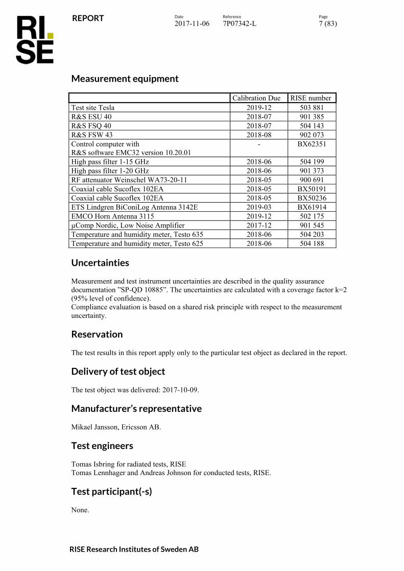
Measurement equipment Calibration Due RISE number Test site Tesla 2019-12 503 881 R&S ESU 40 2018-07 901 385 R&S FSQ 40 2018-07 504 143 R&S FSW 43 2018-08 902 073 Control computer with R&S software EMC32 version 10.20.01
- BX62351
High pass filter 1-15 GHz 2018-06 504 199 High pass filter 1-20 GHz 2018-06 901 373 RF attenuator Weinschel WA73-20-11 2018-05 900 691 Coaxial cable Sucoflex 102EA 2018-05 BX50191 Coaxial cable Sucoflex 102EA 2018-05 BX50236 ETS Lindgren BiConiLog Antenna 3142E 2019-03 BX61914 EMCO Horn Antenna 3115 2019-12 502 175 µComp Nordic, Low Noise Amplifier 2017-12 901 545 Temperature and humidity meter, Testo 635 2018-06 504 203 Temperature and humidity meter, Testo 625 2018-06 504 188
Uncertainties Measurement and test instrument uncertainties are described in the quality assurance documentation ”SP-QD 10885”. The uncertainties are calculated with a coverage factor k=2 (95% level of confidence). Compliance evaluation is based on a shared risk principle with respect to the measurement uncertainty.
Reservation The test results in this report apply only to the particular test object as declared in the report.
Delivery of test object The test object was delivered: 2017-10-09.
Manufacturer’s representative Mikael Jansson, Ericsson AB.
Test engineers Tomas Isbring for radiated tests, RISE Tomas Lennhager and Andreas Johnson for conducted tests, RISE.
Test participant(-s) None.

REPORT
Date Reference Page
2017-11-06 7P07342-L 8 (83)
RISE Research Institutes of Sweden AB
Test frequencies used for radiated and conducted measurements EARFCN Downlink
Frequency [MHz]
Symbolic name
Comment
2407 869.7 B1.4 TX bottom frequency in 1.4 MHz BW configuration 2415 870.5 B3 TX bottom frequency in 3 MHz BW configuration 2425 871.5 B5 TX bottom frequency in 5 MHz BW configuration 2450 874.0 B10 TX bottom frequency in 10 MHz BW configuration 2425 2475
871.5 876.5
B25 2 carriers TX mid constellation with 5 MHz BW configuration
2415 2445 2475 2505 2535 2565
870.5 873.5 876.5 879.5 882.5 885.5
B63 6 carriers TX mid constellation with 3 MHz BW configuration
2525 881.5 M1.4-10 TX mid frequency in 1.4-10 MHz BW configuration 2643 893.3 T1.4 TX top frequency in 1.4 MHz BW configuration 2635 892.5 T3 TX top frequency in 3 MHz BW configuration 2625 891.5 T5 TX top frequency in 5 MHz BW configuration 2600 889.0 T10 TX top frequency in 10 MHz BW configuration 2518 2532
880.8 882.2
M21.4 2 carriers TX mid constellation with 1.4 MHz BW configuration
2407 2421 2593
869.7 871.1 888.3
Bim1.4 3 carriers TX constellation with 1.4 MHz BW configuration
2457 2629 2643
874.7 891.9 893.3
Tim1.4 3 carriers TX constellation with 1.4 MHz BW configuration
2475 2575
876.5 886.5
CA10-10 Carrier Aggregation TX 10 MHz + 10 MHz configuration
2415 870.5 IoT3B TX bottom frequency in 3 MHz BW configuration + NB IoT-
inband in resource block 2
2635 892.5 IoT3T TX top frequency in 3 MHz BW configuration + NB IoT-inband
in resource block 12
2525 881.5 IoT5 TX mid frequency in 5 MHz BW configuration + NB IoT-
inband in resource block 2 All RX frequencies were configured 45 MHz above the corresponding TX frequency according the applicable duplex offset for the operating band.
REPORT
Date Reference Page
2017-11-06 7P07342-L 9 (83)
RISE Research Institutes of Sweden AB
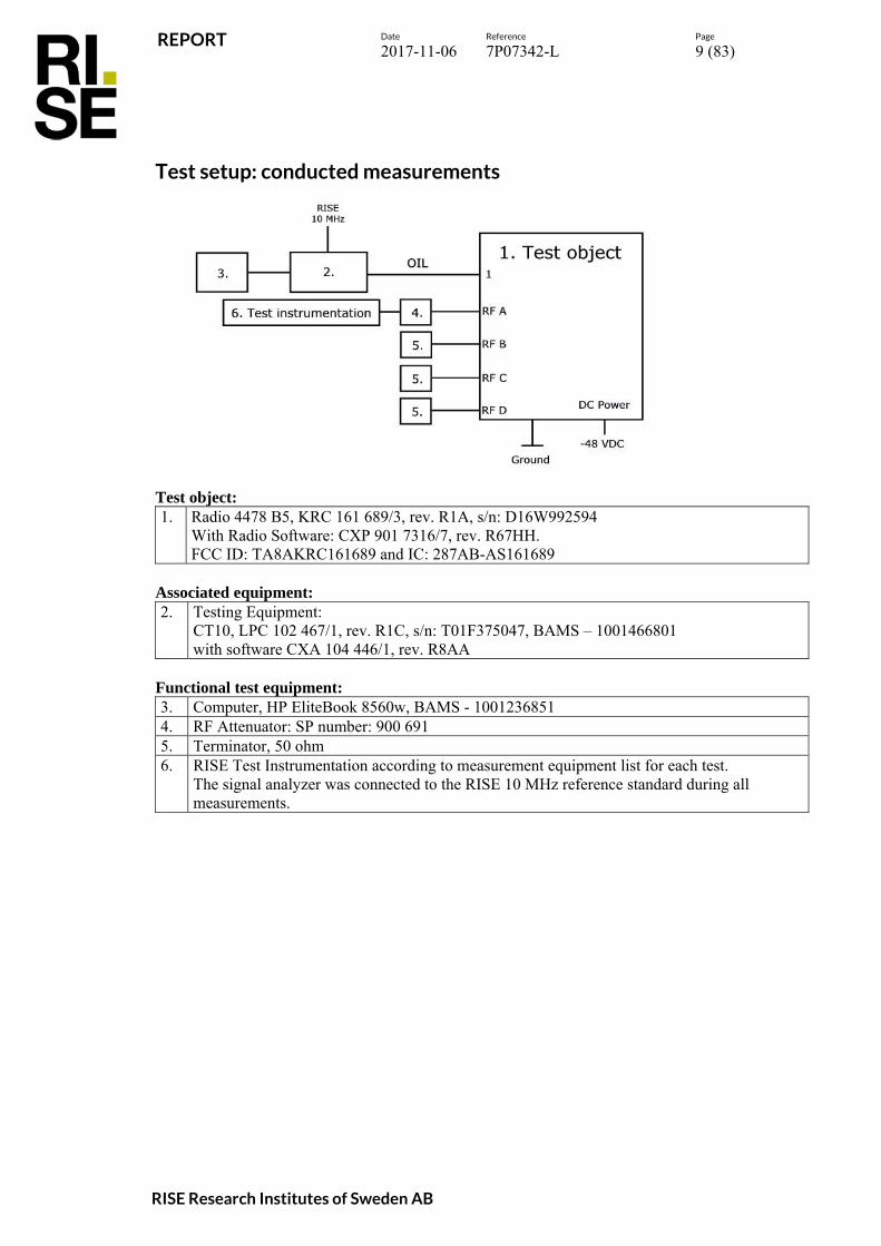
Test setup: conducted measurements
Test object: 1. Radio 4478 B5, KRC 161 689/3, rev. R1A, s/n: D16W992594
With Radio Software: CXP 901 7316/7, rev. R67HH. FCC ID: TA8AKRC161689 and IC: 287AB-AS161689
Associated equipment: 2.
Testing Equipment: CT10, LPC 102 467/1, rev. R1C, s/n: T01F375047, BAMS – 1001466801 with software CXA 104 446/1, rev. R8AA
Functional test equipment: 3. Computer, HP EliteBook 8560w, BAMS - 1001236851 4. RF Attenuator: SP number: 900 691 5. Terminator, 50 ohm 6. RISE Test Instrumentation according to measurement equipment list for each test.
The signal analyzer was connected to the RISE 10 MHz reference standard during all measurements.

REPORT
Date Reference Page
2017-11-06 7P07342-L 10 (83)
RISE Research Institutes of Sweden AB
Test setup: conducted NB IoT-inband measurements
Test object: 1. Radio 4478 B5, KRC 161 689/3, rev. R1A, s/n: D16W992594
With Radio Software: CXP 901 3268/15, rev. R68EG. FCC ID: TA8AKRC161689 and IC: 287AB-AS161689
Associated equipment: 2.
RBS 6601 Main Unit: SUP 6601, 1/BFL 901 009/4, rev. R1E, s/n: BR82691785 DUS 41 01, KDU 137 624/1, rev. R7B, s/n: TU8XV49142 With software: CXP 102 051/27, rev: R27B07
3. Switch Netgear GS108E 4. Computer, HP EliteBook 8560w, BAMS - 1001236851 5. GPS 02 01, NCD 901 41/1, rev. R1D, s/n: A401804384 6. GPS Active Antenna, KRE 101 2082/1
Functional test equipment: 7. RISE Test Instrumentation according to measurement equipment list for each test.
The signal analyzer was connected to the RISE 10 MHz reference standard during all measurements.
8. RF Attenuator: SP number: 900 691 9. Terminator, 50 ohm

REPORT
Date Reference Page
2017-11-06 7P07342-L 11 (83)
RISE Research Institutes of Sweden AB
Test setup: radiated measurements
Test object: 1. Radio 4478 B5, KRC 161 689/3, rev. R1A, s/n: D16W992601
With Radio Software: CXP 901 7316/7, rev. R67HH. FCC ID: TA8AKRC161689 and IC: 287AB-AS161689
Associated equipment: 2.
Testing Equipment: CT10, LPC 102 467/1, rev. R1C, s/n: T01F375047, BAMS – 1001466801 with software CXA 104 446/1, rev. R8AA
Functional test equipment: 3. Computer, HP EliteBook 8560w, BAMS - 1001236851 4. Attenuator 5. R&S ESIB 26, RISE no: 503 292, for supervision purpose only 6. ALD Control, Andrew, model: ATM200-A20, s/n: DESA101412073
REPORT
Date Reference Page
2017-11-06 7P07342-L 12 (83)
RISE Research Institutes of Sweden AB
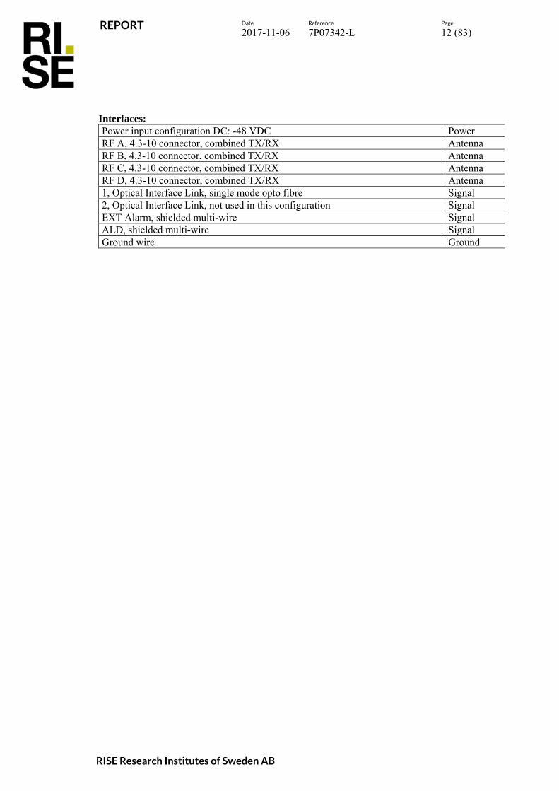
Interfaces: Power input configuration DC: -48 VDC Power RF A, 4.3-10 connector, combined TX/RX Antenna RF B, 4.3-10 connector, combined TX/RX Antenna RF C, 4.3-10 connector, combined TX/RX Antenna RF D, 4.3-10 connector, combined TX/RX Antenna 1, Optical Interface Link, single mode opto fibre Signal 2, Optical Interface Link, not used in this configuration Signal EXT Alarm, shielded multi-wire Signal ALD, shielded multi-wire Signal Ground wire Ground
REPORT
Date Reference Page
2017-11-06 7P07342-L 13 (83)
RISE Research Institutes of Sweden AB
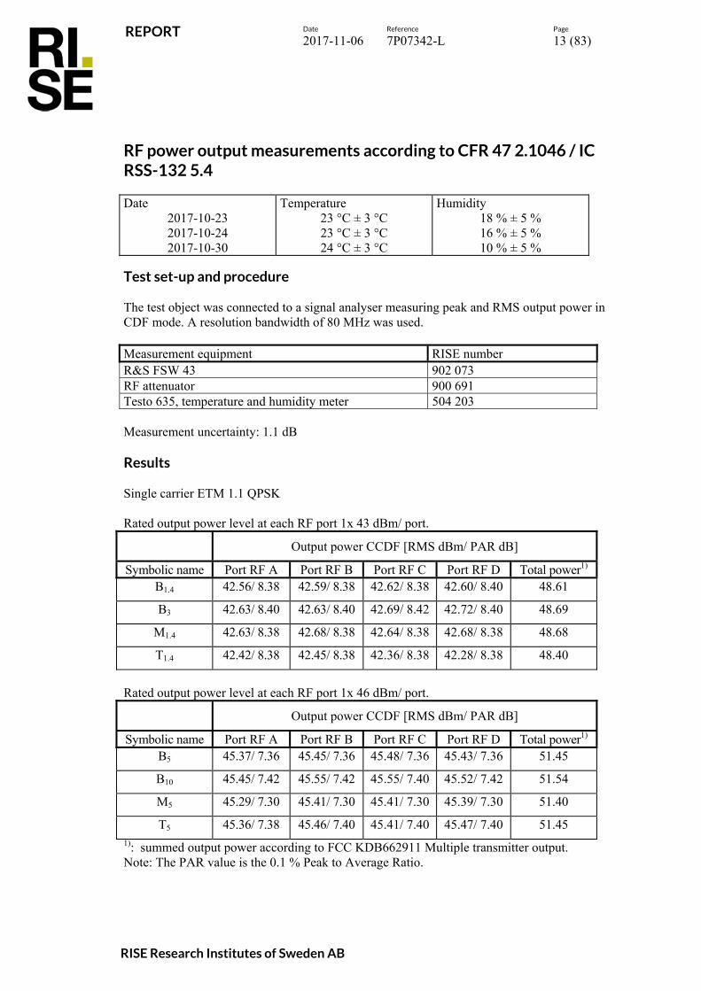
RF power output measurements according to CFR 47 2.1046 / IC RSS-132 5.4 Date
2017-10-23 2017-10-24 2017-10-30
Temperature 23 °C ± 3 °C 23 °C ± 3 °C 24 °C ± 3 °C
Humidity 18 % ± 5 % 16 % ± 5 % 10 % ± 5 %
Test set-up and procedure The test object was connected to a signal analyser measuring peak and RMS output power in CDF mode. A resolution bandwidth of 80 MHz was used. Measurement equipment RISE number R&S FSW 43 902 073 RF attenuator 900 691 Testo 635, temperature and humidity meter 504 203 Measurement uncertainty: 1.1 dB Results Single carrier ETM 1.1 QPSK Rated output power level at each RF port 1x 43 dBm/ port.
Output power CCDF [RMS dBm/ PAR dB]
Symbolic name Port RF A Port RF B Port RF C Port RF D Total power1)
B1.4 42.56/ 8.38 42.59/ 8.38 42.62/ 8.38 42.60/ 8.40 48.61
B3 42.63/ 8.40 42.63/ 8.40 42.69/ 8.42 42.72/ 8.40 48.69
M1.4 42.63/ 8.38 42.68/ 8.38 42.64/ 8.38 42.68/ 8.38 48.68
T1.4 42.42/ 8.38 42.45/ 8.38 42.36/ 8.38 42.28/ 8.38 48.40
Rated output power level at each RF port 1x 46 dBm/ port.
Output power CCDF [RMS dBm/ PAR dB]
Symbolic name Port RF A Port RF B Port RF C Port RF D Total power1)
B5 45.37/ 7.36 45.45/ 7.36 45.48/ 7.36 45.43/ 7.36 51.45
B10 45.45/ 7.42 45.55/ 7.42 45.55/ 7.40 45.52/ 7.42 51.54
M5 45.29/ 7.30 45.41/ 7.30 45.41/ 7.30 45.39/ 7.30 51.40
T5 45.36/ 7.38 45.46/ 7.40 45.41/ 7.40 45.47/ 7.40 51.45 1): summed output power according to FCC KDB662911 Multiple transmitter output. Note: The PAR value is the 0.1 % Peak to Average Ratio.

REPORT
Date Reference Page
2017-11-06 7P07342-L 14 (83)
RISE Research Institutes of Sweden AB
Single carrier ETM 3.2 16QAM Rated output power level at each RF port 1x 46 dBm/ port.
Output power CCDF [RMS dBm/ PAR dB]
symbolic name Port RF A Port RF B Port RF C Port RF D Total power1)
B10 45.46/ 7.42 45.46/ 7.42 45.53/ 7.40 45.48/ 7.42 51.50
Single carrier ETM 3.1 64QAM Rated output power level at each RF port 1x 46 dBm/ port.
Output power CCDF [RMS dBm/ PAR dB]
symbolic name Port RF A Port RF B Port RF C Port RF D Total power1)
B10 45.43/ 7.44 45.45/ 7.44 45.51/ 7.42 45.47/ 7.44 51.49
Single carrier ETM 3.1a 256QAM Rated output power level at each RF port 1x 46 dBm/ port.
Output power CCDF [RMS dBm/ PAR dB]
symbolic name Port RF A Port RF B Port RF C Port RF D Total power1)
B10 45.44/ 7.44 45.47/ 7.44 45.51/ 7.42 45.50/ 7.44 51.50
Multi carrier ETM 1.1 QPSK Rated output power level at each RF port 2x 43 dBm/ port.
Output power CCDF [RMS dBm/ PAR dB]
Symbolic name Port RF A Port RF B Port RF C Port RF D Total power1)
B25 45.56/ 7.32 45.50/7.32 45.59/ 7.28 45.55/ 7.32 51.57
Multi carrier ETM 1.1 QPSK Rated output power level at each RF port 6x 38.2 dBm/ port.
Output power CCDF [RMS dBm/ PAR dB]
Symbolic name Port RF A Port RF B Port RF C Port RF D Total power1)
B63 45.38/ 7.58 45.50/ 7.56 45.39/ 7.48 45.40/ 7.54 51.44 1): summed output power according to FCC KDB662911 Multiple transmitter output
Note: The PAR value is the 0.1 % Peak to Average Ratio.

REPORT
Date Reference Page
2017-11-06 7P07342-L 15 (83)
RISE Research Institutes of Sweden AB
NB-IoT inband NTM Rated output power level at RF connector 1x 43 dBm/ port.
Output power CCDF [RMS dBm/ PAR dB]
Symbolic name Port RF A Port RF B Port RF C Port RF D Total power1)
IoT3B 41.79/ 8.66 41.04/ 8.74 41.11/ 8.82 41.77/ 8.64 47.46
IoT3T 41.31/ 8.60 41.87/ 8.58 41.93/ 8.44 41.81/ 8.36 47.76
NB-IoT inband NTM Rated output power level at RF connector 1x 46 dBm/ port.
Output power CCDF [RMS dBm/ PAR dB]
Symbolic name Port RF A Port RF B Port RF C Port RF D Total power1)
IoT5 44.53/ 8.04 44.53/ 8.08 45.09/ 7.76 44.70/ 8.06 50.74
Single carrier ETM 1.1 QPSK Rated output power level at RF connector 1x 43 dBm/ port.
Output power per 1 MHz [RMS dBm]
Symbolic name Port RF A Port RF B Port RF C Port RF D Total power1)
B1.4 41.58 41.63 41.71 41.60 47.65
B3 38.71 38.71 38.82 38.72 44.76
IoT3T 37.43 38.31 37.46 37.47 43.70
Rated output power level at RF connector 1x 46 dBm/ port.
Output power per 1 MHz [RMS dBm]
Symbolic name Port RF A Port RF B Port RF C Port RF D Total power1)
B5 39.48 39.52 39.52 39.49 45.52
B10 36.59 36.60 36.60 36.57 42.61
1): summed output power according to FCC KDB662911 Multiple transmitter output.

REPORT
Date Reference Page
2017-11-06 7P07342-L 16 (83)
RISE Research Institutes of Sweden AB
Remark This unit is tested without antenna. ERP/EIRP compliance is addressed at the time of licensing, as required by the responsible FCC/IC Bureau(s). Licensee’s are required to take into account maximum allowed antenna gain used in combination with above power settings to prevent the radiated output power to exceed the limits. Limits CFR47 § 22.913: The effective radiated power ERP shall not exceed 1000 W or 800 W/ MHz
(PSD) per sector. The PAR (0.1%) shall not exceed 13 dB.
RSS-132 5.4: The average equivalent isotropically radiated power (e.i.r.p.) limits in SRSP-503 apply, resulting in a maximum EIRP of 1640 W. The PAR (0.1%) shall not exceed 13 dB.
Complies? Yes

REPORT
Date Reference Page
2017-11-06 7P07342-L 17 (83)
RISE Research Institutes of Sweden AB
Occupied bandwidth measurements according to CFR47 2.1049 / RSS-Gen 4.6.1 Date
2017-10-25 2017-10-30
Temperature 24 °C ± 3 °C 24 °C ± 3 °C
Humidity 29 % ± 5 % 10 % ± 5 %
Test set-up and procedure The measurements were made per definition in § 2.1049. The output was connected to a signal analyzer with the Peak detector activated in max hold. Measurement equipment RISE number R&S FSW 43 902 073 RF attenuator 900 691 Testo 635, temperature and humidity meter 504 203 Measurement uncertainty: 3.7 dB Results Single carrier ETM 1.1 Diagram Symbolic name Tested Port Occupied BW
(99%) [MHz] 1 M5 RF B 4.477
Single carrier ETM 3.1 Diagram Symbolic name Tested Port Occupied BW
(99%) [MHz] 2 M5 RF A 4.494 3 B1.4 RF B 1.101 4 B10 RF B 8.975 5 M1.4 RF B 1.101 6 M3 RF B 2.695 7 M5 RF B 4.494 8 M10 RF B 8.975 9 T1.4 RF B 1.101 10 T10 RF B 8.977 11 M5 RF C 4.495 12 M5 RF D 4.493
REPORT
Date Reference Page
2017-11-06 7P07342-L 18 (83)
RISE Research Institutes of Sweden AB
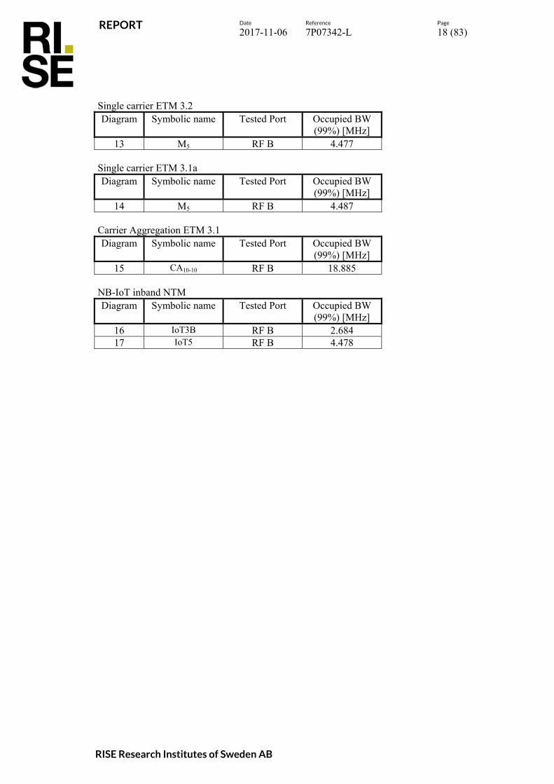
Single carrier ETM 3.2 Diagram Symbolic name Tested Port Occupied BW
(99%) [MHz] 13 M5 RF B 4.477
Single carrier ETM 3.1a Diagram Symbolic name Tested Port Occupied BW
(99%) [MHz] 14 M5 RF B 4.487
Carrier Aggregation ETM 3.1 Diagram Symbolic name Tested Port Occupied BW
(99%) [MHz] 15 CA10-10 RF B 18.885
NB-IoT inband NTM Diagram Symbolic name Tested Port Occupied BW
(99%) [MHz] 16 IoT3B RF B 2.684 17 IoT5 RF B 4.478

REPORT
Date Reference Page
2017-11-06 7P07342-L 19 (83)
RISE Research Institutes of Sweden AB
Diagram 1:
Diagram 2:

REPORT
Date Reference Page
2017-11-06 7P07342-L 20 (83)
RISE Research Institutes of Sweden AB
Diagram 3:
Diagram 4:

REPORT
Date Reference Page
2017-11-06 7P07342-L 21 (83)
RISE Research Institutes of Sweden AB
Diagram 5:
Diagram 6:

REPORT
Date Reference Page
2017-11-06 7P07342-L 22 (83)
RISE Research Institutes of Sweden AB
Diagram 7:
Diagram 8:

REPORT
Date Reference Page
2017-11-06 7P07342-L 23 (83)
RISE Research Institutes of Sweden AB
Diagram 9:
Diagram 10:

REPORT
Date Reference Page
2017-11-06 7P07342-L 24 (83)
RISE Research Institutes of Sweden AB
Diagram 11:
Diagram 12:

REPORT
Date Reference Page
2017-11-06 7P07342-L 25 (83)
RISE Research Institutes of Sweden AB
Diagram 13:
Diagram 14:

REPORT
Date Reference Page
2017-11-06 7P07342-L 26 (83)
RISE Research Institutes of Sweden AB
Diagram 15:
Diagram 16:

REPORT
Date Reference Page
2017-11-06 7P07342-L 27 (83)
RISE Research Institutes of Sweden AB
Diagram 17:

REPORT
Date Reference Page
2017-11-06 7P07342-L 28 (83)
RISE Research Institutes of Sweden AB
Band edge measurements according to CFR 47 §2.1051 / IC RSS-132 5.5 Date
2017-10-25 2017-10-30
Temperature 24 °C ± 3 °C 24 °C ± 3 °C
Humidity 29 % ± 5 % 10 % ± 5 %
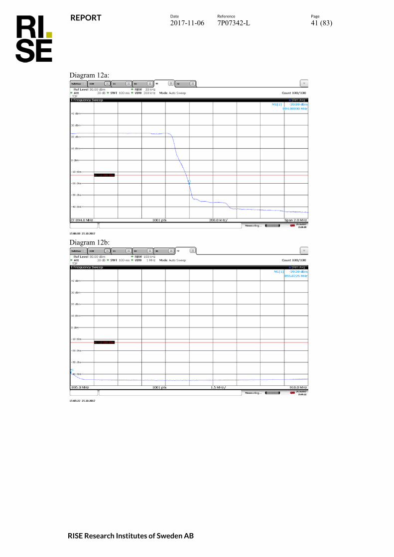
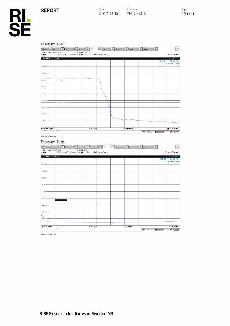
Test set-up and procedure The measurements were made per definition in § 22.917. The test object was connected to a spectrum analyzer with the RMS detector activated. The spectrum analyzer was connected to an external 10 MHz reference standard during the measurements. Before comparing the results to the limit, 6 dB [10 log (4)] to cover 4x4 MIMO, should be added according to method c “measure and add 10 log(NANT)” of FCC KDB662911 D01 Multiple Transmitter Output. Measurement equipment RISE number R&S FSW 43 902 073 RF attenuator 900 691 Testo 635, temperature and humidity meter 504 203 Measurement uncertainty: 3.7 dB
Results Single carrier TM 1.1
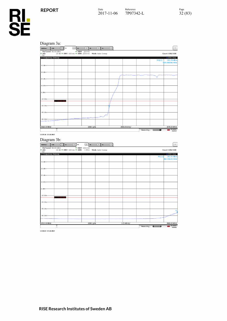
Diagram Symbolic name Tested Port 1 a-b B3 RF A 2 a-b T3 RF A 3 a-b B1.4 RF B 4 a-b B3 RF B 5 a-b B5 RF B 6 a-b B10 RF B 7 a-b T1.4 RF B 8 a-b T3 RF B 9 a-b T5 RF B
10 a-b T10 RF B 11 a-b B3 RF C 12 a-b T3 RF C 13 a-b B3 RF D 14 a-b T3 RF D
Multi carrier TM 1.1
Diagram Symbolic name Tested Port 15 a-b Bim RF B 16 a-b Tim RF B

REPORT
Date Reference Page
2017-11-06 7P07342-L 29 (83)
RISE Research Institutes of Sweden AB
NB-IoT inband NTM Diagram Symbolic name Tested Port 17 a-b IoT3B RF B 18 a-b IoT3T RF B
The diagrams are shown on the following pages. Limits CFR 47 § 22.917: Outside a licensee's frequency band(s) of operation the power of any emission shall be attenuated below the transmitter power (P) by at least 43 + 10 log (P) dB, resulting in a limit of -13 dBm per 100 kHz RBW below 1 GHz and 1MHz RBW above 1 GHz. IC RSS-132 5.5: Outside a licensee's frequency band(s) of operation the power of any emission shall be attenuated below the transmitter power (P) by at least 43 + 10 log (P) dB per any 100 kHz RBW. Complies? Yes

REPORT
Date Reference Page
2017-11-06 7P07342-L 30 (83)
RISE Research Institutes of Sweden AB
Diagram 1a:
Diagram 1b:

REPORT
Date Reference Page
2017-11-06 7P07342-L 31 (83)
RISE Research Institutes of Sweden AB
Diagram 2a:
Diagram 2b:
REPORT
Date Reference Page
2017-11-06 7P07342-L 32 (83)
RISE Research Institutes of Sweden AB
Diagram 3a:
Diagram 3b:

REPORT
Date Reference Page
2017-11-06 7P07342-L 33 (83)
RISE Research Institutes of Sweden AB
Diagram 4a:
Diagram 4b:

REPORT
Date Reference Page
2017-11-06 7P07342-L 34 (83)
RISE Research Institutes of Sweden AB
Diagram 5a:
Diagram 5b:

REPORT
Date Reference Page
2017-11-06 7P07342-L 35 (83)
RISE Research Institutes of Sweden AB
Diagram 6a:
Diagram 6b:

REPORT
Date Reference Page
2017-11-06 7P07342-L 36 (83)
RISE Research Institutes of Sweden AB
Diagram 7a:
Diagram 7b:

REPORT
Date Reference Page
2017-11-06 7P07342-L 37 (83)
RISE Research Institutes of Sweden AB
Diagram 8a:
Diagram 8b:

REPORT
Date Reference Page
2017-11-06 7P07342-L 38 (83)
RISE Research Institutes of Sweden AB
Diagram 9a:
Diagram 9b:

REPORT
Date Reference Page
2017-11-06 7P07342-L 39 (83)
RISE Research Institutes of Sweden AB
Diagram 10a:
Diagram 10b:

REPORT
Date Reference Page
2017-11-06 7P07342-L 40 (83)
RISE Research Institutes of Sweden AB
Diagram 11a:
Diagram 11b:
REPORT
Date Reference Page
2017-11-06 7P07342-L 41 (83)
RISE Research Institutes of Sweden AB
Diagram 12a:
Diagram 12b:

REPORT
Date Reference Page
2017-11-06 7P07342-L 42 (83)
RISE Research Institutes of Sweden AB
Diagram 13a:
Diagram 13b:

REPORT
Date Reference Page
2017-11-06 7P07342-L 43 (83)
RISE Research Institutes of Sweden AB
Diagram 14a:
Diagram 14b:

REPORT
Date Reference Page
2017-11-06 7P07342-L 44 (83)
RISE Research Institutes of Sweden AB
Diagram 15a:
Diagram 15b:
REPORT
Date Reference Page
2017-11-06 7P07342-L 45 (83)
RISE Research Institutes of Sweden AB
Diagram 16a:
Diagram 16b:

REPORT
Date Reference Page
2017-11-06 7P07342-L 46 (83)
RISE Research Institutes of Sweden AB
Diagram 17a:
Diagram 17b:

REPORT
Date Reference Page
2017-11-06 7P07342-L 47 (83)
RISE Research Institutes of Sweden AB
Diagram 18a:
Diagram 18b:
REPORT
Date Reference Page
2017-11-06 7P07342-L 48 (83)
RISE Research Institutes of Sweden AB
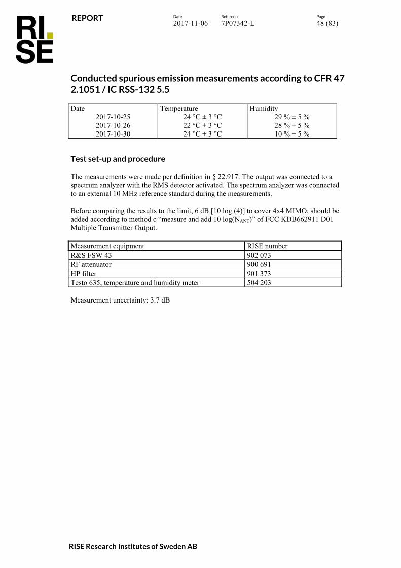
Conducted spurious emission measurements according to CFR 47 2.1051 / IC RSS-132 5.5 Date
2017-10-25 2017-10-26 2017-10-30
Temperature 24 °C ± 3 °C 22 °C ± 3 °C 24 °C ± 3 °C
Humidity 29 % ± 5 % 28 % ± 5 % 10 % ± 5 %
Test set-up and procedure The measurements were made per definition in § 22.917. The output was connected to a spectrum analyzer with the RMS detector activated. The spectrum analyzer was connected to an external 10 MHz reference standard during the measurements. Before comparing the results to the limit, 6 dB [10 log (4)] to cover 4x4 MIMO, should be added according to method c “measure and add 10 log(NANT)” of FCC KDB662911 D01 Multiple Transmitter Output. Measurement equipment RISE number R&S FSW 43 902 073 RF attenuator 900 691 HP filter 901 373 Testo 635, temperature and humidity meter 504 203 Measurement uncertainty: 3.7 dB

REPORT
Date Reference Page
2017-11-06 7P07342-L 49 (83)
RISE Research Institutes of Sweden AB
Results Single carrier E-TM 1.1
Diagram Symbolic name Tested Port 1 a-b B5 RFA 2 a-b T5 RF A 3 a-b B5 RF B 4 a-b M5 RF B 5 a-b T1.4 RF B 6 a-b T3 RF B 7 a-b T5 RF B 8 a-b T10 RF B 9 a-b T5 RF C
10 a-b T5 RF D Multi carrier E-TM 1.1
Diagram Symbolic name Tested Port 11 a-c B2 RF B 12 a-c B6 RF B 13 a-c Bim RF B 14 a-c Tim RF B
NB IoT-inband NTM
Diagram Symbolic name Tested Port 15 a-c IoT3B RF B 16 a-c IoT3T RF B 17 a-c IoT5 RF B
Note: Measurements were mainly limited to port RF B due to the measurement result in single carrier mode that shows that the ports are electrical identical as declared by the client.
REPORT
Date Reference Page
2017-11-06 7P07342-L 50 (83)
RISE Research Institutes of Sweden AB
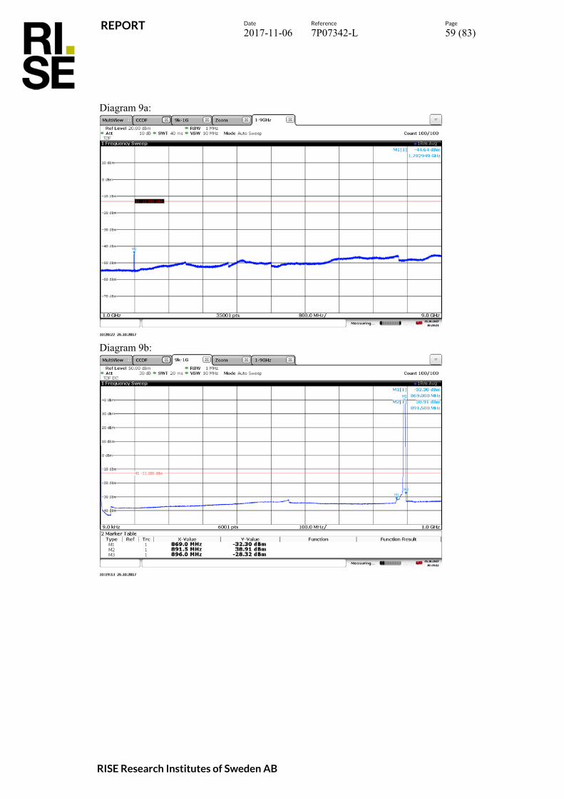
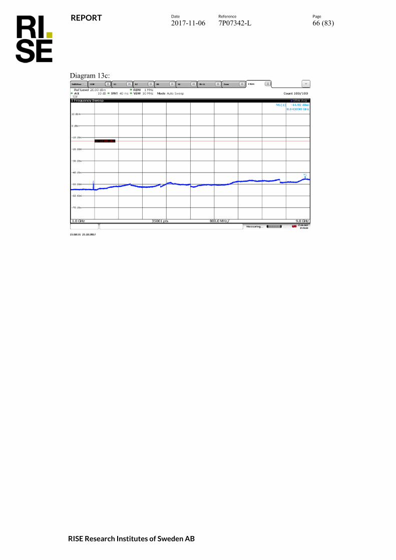
Remark The emission at 9 kHz on the plots was not generated by the test object. A complementary measurement with a smaller RBW showed that it was related to the LO feed-through. The highest fundamental frequency is 894 MHz. The measurements were made up to 9 GHz (10x894 MHz = 8.940 GHz). Limits CFR 47 § 22.917: Outside a licensee's frequency band(s) of operation the power of any emission shall be attenuated below the transmitter power (P) by at least 43 + 10 log (P) dB, resulting in a limit of -13 dBm per 100 kHz RBW below 1 GHz and 1MHz RBW above 1 GHz. IC RSS-132 5.5: Outside a licensee's frequency band(s) of operation the power of any emission shall be attenuated below the transmitter power (P) by at least 43 + 10 log (P) dB per any 100 kHz RBW. Complies? Yes

REPORT
Date Reference Page
2017-11-06 7P07342-L 51 (83)
RISE Research Institutes of Sweden AB
Diagram 1a:
Diagram 1b:

REPORT
Date Reference Page
2017-11-06 7P07342-L 52 (83)
RISE Research Institutes of Sweden AB
Diagram 2a:
Diagram 2b:

REPORT
Date Reference Page
2017-11-06 7P07342-L 53 (83)
RISE Research Institutes of Sweden AB
Diagram 3a:
Diagram 3b:

REPORT
Date Reference Page
2017-11-06 7P07342-L 54 (83)
RISE Research Institutes of Sweden AB
Diagram 4a:
Diagram 4b:

REPORT
Date Reference Page
2017-11-06 7P07342-L 55 (83)
RISE Research Institutes of Sweden AB
Diagram 5a:
Diagram 5b:

REPORT
Date Reference Page
2017-11-06 7P07342-L 56 (83)
RISE Research Institutes of Sweden AB
Diagram 6a:
Diagram 6b:

REPORT
Date Reference Page
2017-11-06 7P07342-L 57 (83)
RISE Research Institutes of Sweden AB
Diagram 7a:
Diagram 7b:

REPORT
Date Reference Page
2017-11-06 7P07342-L 58 (83)
RISE Research Institutes of Sweden AB
Diagram 8a:
Diagram 8b:
REPORT
Date Reference Page
2017-11-06 7P07342-L 59 (83)
RISE Research Institutes of Sweden AB
Diagram 9a:
Diagram 9b:

REPORT
Date Reference Page
2017-11-06 7P07342-L 60 (83)
RISE Research Institutes of Sweden AB
Diagram 10a:
Diagram 10b:

REPORT
Date Reference Page
2017-11-06 7P07342-L 61 (83)
RISE Research Institutes of Sweden AB
Diagram 11a:
Diagram 11b:
Note: The limit in the diagram shall be -13 dBm instead of -23 dBm.

REPORT
Date Reference Page
2017-11-06 7P07342-L 62 (83)
RISE Research Institutes of Sweden AB
Diagram 11c:

REPORT
Date Reference Page
2017-11-06 7P07342-L 63 (83)
RISE Research Institutes of Sweden AB
Diagram 12a:
Diagram 12b:
Note: The limit in the diagram shall be -13 dBm instead of -23 dBm.

REPORT
Date Reference Page
2017-11-06 7P07342-L 64 (83)
RISE Research Institutes of Sweden AB
Diagram 12c:

REPORT
Date Reference Page
2017-11-06 7P07342-L 65 (83)
RISE Research Institutes of Sweden AB
Diagram 13a:
Diagram 13b:
Note: The limit in the diagram shall be -13 dBm instead of -23 dBm.
REPORT
Date Reference Page
2017-11-06 7P07342-L 66 (83)
RISE Research Institutes of Sweden AB
Diagram 13c:

REPORT
Date Reference Page
2017-11-06 7P07342-L 67 (83)
RISE Research Institutes of Sweden AB
Diagram 14a:
Diagram 14b:
Note: The limit in the diagram shall be -13 dBm instead of -23 dBm.

REPORT
Date Reference Page
2017-11-06 7P07342-L 68 (83)
RISE Research Institutes of Sweden AB
Diagram 14c:

REPORT
Date Reference Page
2017-11-06 7P07342-L 69 (83)
RISE Research Institutes of Sweden AB
Diagram 15a:
Diagram 15b:
Note: The limit in the diagram shall be -13 dBm instead of -23 dBm.

REPORT
Date Reference Page
2017-11-06 7P07342-L 70 (83)
RISE Research Institutes of Sweden AB
Diagram 15c:

REPORT
Date Reference Page
2017-11-06 7P07342-L 71 (83)
RISE Research Institutes of Sweden AB
Diagram 16a:
Diagram 16b:
Note: The limit in the diagram shall be -13 dBm instead of -23 dBm.

REPORT
Date Reference Page
2017-11-06 7P07342-L 72 (83)
RISE Research Institutes of Sweden AB
Diagram 16c:

REPORT
Date Reference Page
2017-11-06 7P07342-L 73 (83)
RISE Research Institutes of Sweden AB
Diagram 17a:
Diagram 17b:
Note: The limit in the diagram shall be -13 dBm instead of -23 dBm.

REPORT
Date Reference Page
2017-11-06 7P07342-L 74 (83)
RISE Research Institutes of Sweden AB
Diagram 17c:

REPORT
Date Reference Page
2017-11-06 7P07342-L 75 (83)
RISE Research Institutes of Sweden AB
Field strength of spurious radiation measurements according to 47 CFR 2.1053 / IC RSS-133 5.5 Date
2017-10-18 Temperature
22 °C ± 3 °C Humidity
42 % ± 5 % The test site conform to the site validation criterion specified in ANSI C63.4 2014. The test site complies with RSS-Gen, Industry Canada file no. 3482A-1. The measurements were performed with both horizontal and vertical polarization of the antenna. The antenna distance and test object height in the different frequency ranges can been seen below. The measurements were performed with both horizontal and vertical polarization of the antenna. The antenna distance was 3 m. RF absorbers were covering a floor area in the frequency range 1 GHz – 9 GHz to comply with site validation requirements according to ANSI C63.4-2014. The EUT was placed 0.8 m above reference ground plane in frequency range 30 MHz – 1 GHz and 1.5 m above reference ground plane in frequency range 1 GHz – 9 GHz. The measurement was performed with a RBW of 1 MHz. A propagation loss in free space was calculated. The used formula was
420 log
D
, is the propagation loss and D is the antenna distance.
The measurement procedure was as the following: 1. A pre-measurement is performed with peak detector. For measurement < 1 GHz the
test object was measured in eight directions with the antenna at three heights, 1.0 m, 1.5 m and 2.0 m. For measurements > 1 GHz the test object was measured in seventeen directions with the antenna height 1.0 m and 1.5 m.
2. Spurious radiation on frequencies closer than 20 dB to the limit in the pre-measurement is scanned 0-360 degrees and the antenna is scanned 1- 4 m for maximum response. The emission is then measured with the RMS detector and the RMS value is reported. Frequencies closer than 10 dB to the limit when measured with the RMS detector were measured with the substitution method according to ANSI 63.26.

REPORT
Date Reference Page
2017-11-06 7P07342-L 76 (83)
RISE Research Institutes of Sweden AB
The test set-up during the spurious radiation measurements is shown in the pictures below: 30-1000 MHz:
1-9 GHz:

REPORT
Date Reference Page
2017-11-06 7P07342-L 77 (83)
RISE Research Institutes of Sweden AB
Measurement equipment Measurement equipment RISE number Semi anechoic chamber Tesla 503 881 R&S ESU 40 901 385 R&S software EMC32 version 10.20.01 BX62351 ETS Lindgren BiConiLog 3142E BX61914 ETS Lindgren Horn Antenna 3115 502 175 µComp Nordic, Low Noise Amplifier 901 545 HP Filter 1-20 GHz 901 501 Temperature and humidity meter, Testo 625 504 188 Results representing worst case: Symbolic name M5, TX mid frequency, BW 5 MHz, Diagram 1 a-b
Frequency (MHz)
Spurious emission level (dBm)
Vertical Horizontal
30-9000 All emission > 20 dB below limit All emission > 20 dB below limit
Measurement uncertainty: 3.1 dB Limits CFR 47 §22.917 and IC RSS-132 5.6 Outside a licensee's frequency band(s) of operation the power of any emission shall be attenuated below the transmitter power (P) by at least 43 + 10 log (P) dB, resulting in a limit of -13 dBm. Complies? Yes

REPORT
Date Reference Page
2017-11-06 7P07342-L 78 (83)
RISE Research Institutes of Sweden AB
Diagram 1a:
Note: The emission at 881.5 MHz is the carrier frequency and shall be ignored in the context. Diagram 1b:
-70
-60
-50
-40
-30
-20
-10
0
30M 50 60 80 100M 200 300 400 500 800 1G
Leve
l in
dBm
Frequency in Hz
FCC P2
-70
-60
-50
-40
-30
-20
-10
0
1G 2G 3G 4G 5G 6 7 8 9G
Leve
l in
dBm
Frequency in Hz
FCC P2

REPORT
Date Reference Page
2017-11-06 7P07342-L 79 (83)
RISE Research Institutes of Sweden AB
Frequency stability measurements according to CFR 47 §22.355 , 2.1055 / IC RSS 132 5.3 Date
2017-10-17 2017-10-18 2017-10-19 2017-10-26
Temperature (test equipment) 22 °C ± 3 °C 22 °C ± 3 °C 22 °C ± 3 °C 22 °C ± 3 °C
Humidity (test equipment)
32 % ± 5 % 39 % ± 5 % 20 % ± 5 % 28 % ± 5 %
Test set-up and procedure The measurement was made per 3GPP TS 36.141. The output was connected to a spectrum analyser. The spectrum analyser was connected to an external 10 MHz reference standard during the measurements. Measurement equipment RISE number Rohde & Schwarz signal analyzer FSQ 40 504 143 Rohde & Schwarz signal analyzer FSW 43 902 073 RF attenuator 900 691 Temperature Chamber 503 360 Testo 635, temperature and humidity meter 504 203 Multimeter Fluke 87 502 190

REPORT
Date Reference Page
2017-11-06 7P07342-L 80 (83)
RISE Research Institutes of Sweden AB
Results Nominal transmitter frequency was 881.5 MHz (M) with a bandwidth of 5 MHz. Rated output power level at connector RF A (maximum): 46 dBm.
Test conditions
Frequency error (Hz) Supply voltage
DC (V) Temp. (°C)
40.8 +20 4 55.2 +20 3 48 +20 3 48 +30 4 48 +40 4 48 +50 5 48 +10 4 48 0 4 48 -10 4 48 -20 3 48 -30 4
Maximum freq. error (Hz) 5
Measurement uncertainty < ± 1 x 10⁻⁷
Remark It was deemed sufficient to test one combination of TX frequency, channel bandwidth configuration and test model (modulation), as all combinations share a common internal reference to derive the TX frequency from. Limits Limit according to: 3GPP TS 36.141: The frequency error shall be within ± 0.05 PPM ± 12 Hz ( ± 44.075Hz). §22.355 The frequency stability shall be within ± 1.5 ppm ( ± 1322.25 Hz). RSS-132 5.3 Frequency: The carrier frequency shall not depart from the reference frequency in excess of ± 1.5 ppm ( ± 1322.25 Hz) for base stations when tested to the temperature and supply voltage variations specified in RSS-Gen. Complies? Yes
REPORT
Date Reference Page
2017-11-06 7P07342-L 81 (83)
RISE Research Institutes of Sweden AB
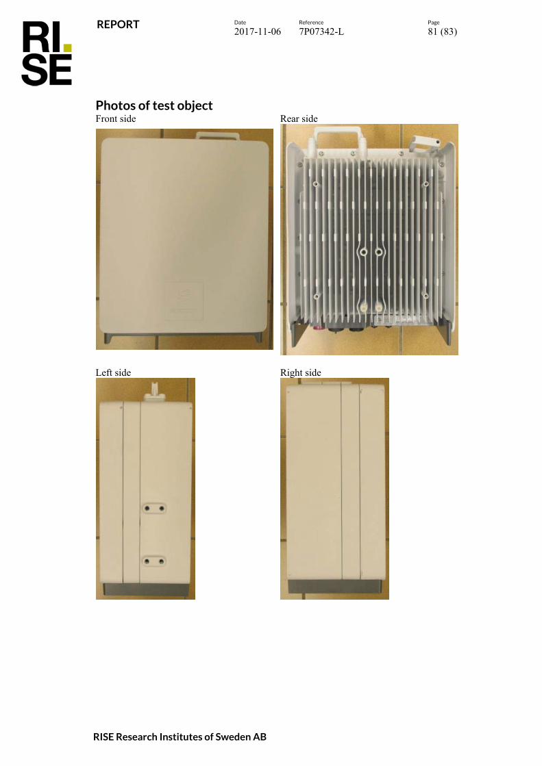
Photos of test object Front side Rear side
Left side Right side

REPORT
Date Reference Page
2017-11-06 7P07342-L 82 (83)
RISE Research Institutes of Sweden AB
Bottom side
Top side

REPORT
Date Reference Page
2017-11-06 7P07342-L 83 (83)
RISE Research Institutes of Sweden AB
Labels: Radiated measurements: Test object label:
SFP module:
Conducted measurements: Test object label:
SFP module: