report - heat balance of a reheating walking beam furnace - vsp
TRANSCRIPT

HEAT BALANCE OF REHEATING WALKING
BEAM FURNACE
Submitted by
NAME: N.V.S.KALYAN ADMN. NO.: 2012JE1025
DEPARTMENT OF MECHANICAL ENGINEERING
INDIAN SCHOOL OF MINES, DHANBAD
Under the guidance of
N. VENUGOPALA RAO, AGM (M), EMP. NO: 116986, DEPT. MMSM, VISAKHAPATNAM STEEL PLANT.

VIZAG STEEL PLANT - MMSM CERTIFICATE
This is to certify that the Project Report on HEAT BALANCE
OF REHEATING WALKING BEAM FURNACE submitted by
NAME: N.V.S.KALYAN ADMN. NO.: 2012JE1025
COLLEGE: INDIAN SCHOOL OF MINES, DHANBAD
is a record of Bonafide work carried out by him, under the
guidance and supervision during the period of 18th MAY
2015 to 30th MAY 2015.
N. VENUGOPALA RAO,
AGM (M),
DEPT. MMSM,
VISAKHAPATNAM STEEL PLANT.

CONTENTS
INTRODUCTION - STEEL
WORLD STEEL STATISTICS
INDIAN STEEL INDUSTRY
VIZAG STEEL PLANT - RINL
MEDIUM MERCHANT AND STRUCTURAL MILL (MMSM)
INDUSTRIAL FURNACE
WALKING BEAM REHEATING FURNACE
THERMAL ANALYSIS OF THE FURNACE
OBSERVATIONS
CALCULATIONS
HEAT BALANCE SHEET
CONCLUSIONS

INTRODUCTION
STEEL
Steels are alloys of Iron and Carbon, widely used in
construction and other applications because of its high tensile
strength and low cost. The Carbon in typical Steel alloy may
contribute up to 2.1% of its weight. Varying the amount of
alloying elements, their formation in the steel either as solute
elements or as precipitated phases controls the qualities of
steel such as Hardness, Ductility and Tensile Strength.
For many thousands of years steel used to be produced
in Bloomery furnaces but after the efficient production
methods for Blister Steel and Crucible Steel in 17th century,
expansion of steel took extensively. With the invention of
Bessemer process in the mid-19th century, a new era of mass
produced steel began and this was followed by the
introduction of Siemens-Martin process and Gilchrist-Thomas

process of Quality of Steel. With these introductions Mild
Steel replaced Wrought Iron.
Further refinements in the process, such as basic oxygen
steelmaking (BOS), largely replaced earlier methods by
further lowering the cost of production and increasing the
quality of the metal. Now, Steel is one of the most commonly
used engineering materials in the world, with more than 1.3
billion tons being produced annually. It is a major component
in buildings, infrastructure, tools, ships, automobiles,
machines, appliances and weapons.
Generally Steels are of two kinds, namely Plain Carbon
Steel and Alloy Steel. Carbon Steel is simply composed of
Iron and Carbon. It is again divided into three kinds, namely
Low Carbon Steel or Mild Steel, Medium Carbon Steel and
High Carbon Steel. Low Carbon Steel by weight consists
carbon from 0.05% to 0.3%. It is made basic oxygen and open
hearth furnaces and is used for forging work, rivets, chains
and machine parts that does not need high strength. Medium
Carbon Steel has more carbon content and is more stronger
than Mild Steel. It is also difficult to cut, bend and weld
compared to Low Carbon Steel. It generally contains 0.3% to
0.6% carbon by weight. It is used for making of bolts, shafts,
car axles, rails and other parts or tools that require strong
metal. High Carbon Steel, also known as Carbon Tool Steel,
contains 0.6% to 1.5% carbon by weight. The best grades of
this steel is manufactured in Electric furnace. It is used to

make tools such as crowbars, drills, taps, dies, reamers, files,
cold chisels and hammers.
Alloy Steels are obtained by combining steel with one or
more other elements, usually metals. These steel are
generally heat treated for improving properties such as
increased hardenability, corrosion resistance and retention of
hardness and strength at high temperatures. There are three
classes of Alloy steels, namely Constructional Alloy Steel,
Alloy Tool Steel and Special Alloy Steel. Constructional Alloy
Steel is used for making of shafts, gears, levers, springs, bolts,
piston pins, connecting rods and steel used for construction
of buildings, bridges, auto frames, railroads and ships. Total
alloy content of these steel ranges from 0.25% to about 6%.
Alloy Tool Steel is used for making of cutting and forming
tools. The total alloy content of this steel ranges from 0.25%
to 38%. Special Alloy Steels are designed for extreme service
requirements. They include steels with very high heat,
corrosion or wear resistance.
WORLD STEEL STATISTICS
Steel is a cornerstone and key driver for the world’s
economy. The steel industry directly employs more than two
million people worldwide, plus two million contractors and
four million people in supporting industries. Including
industries such as construction, transport and energy, the
steel industry is a source of employment for more than 50
million people. It is at the core of the green economy, in

which economic growth and environmental responsibility
work hand in hand. It is the main material used in delivering
renewable energy: solar, tidal and wind. Steel is 100%
recyclable and can be used in new products and applications
amounting to significant energy and raw material savings. The
amount of energy required to produce a tonne of steel has
been reduced by 50% in the past 30 years.
Steel is everywhere in our lives. No other material has
the same unique combination of strength, formability and
versatility. Steel surfaces are hygienic and easy to clean.
Surgical and safety equipment and commercial kitchens are
all made with steel. Almost 200 billion cans of food are
produced each year. Steel cans ensure that food remains safe
and nutritious while saving energy as refrigeration is not
needed. Steel is an innovative and progressive industry
committed to the safety and health of its people. The
industry is committed to the goal of an injury-free workplace.
Safety metrics show that the lost-time injury frequency rate is
decreasing. Globally, the steel industry spends more than €12
billion per year on process improvements, new product
development and future breakthrough technology.
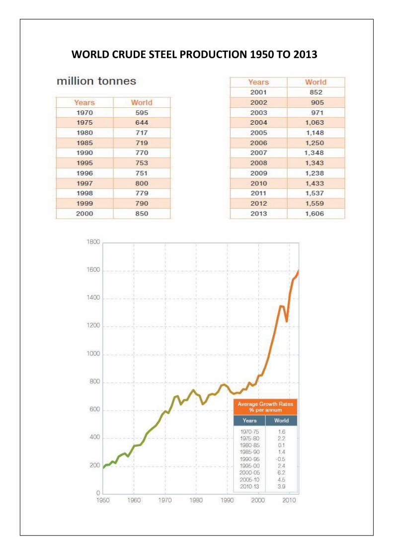
WORLD CRUDE STEEL PRODUCTION 1950 TO 2013
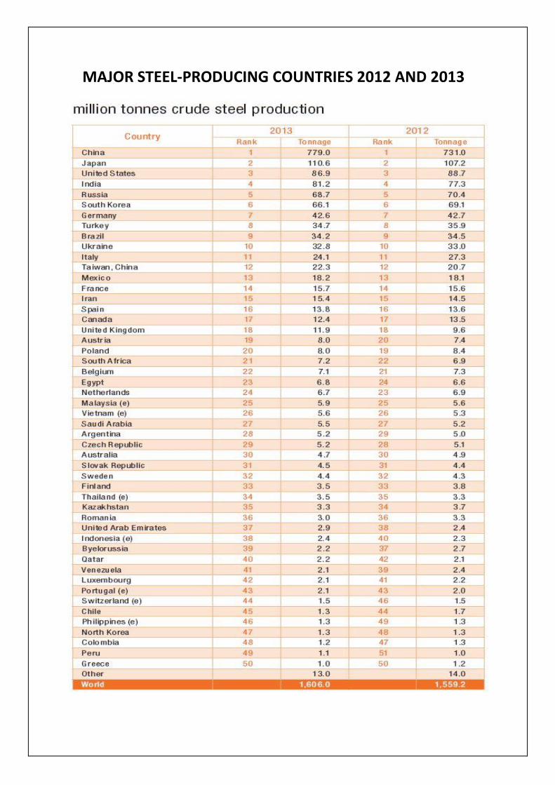
MAJOR STEEL-PRODUCING COUNTRIES 2012 AND 2013

TOP STEEL-PRODUCING COMPANIES 2013
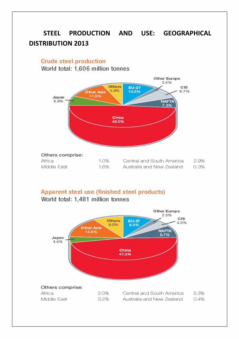
STEEL PRODUCTION AND USE: GEOGRAPHICAL
DISTRIBUTION 2013

WORLD IRON ORE TRADE BY AREA 2013
MAJOR IMPORTERS AND EXPORTERS OF STEEL 2013

INDIAN STEEL INDUSTRY
The Indian steel industry has entered into a new era of
development since 2007-08, riding high on the resurgent
economy and robust demand for steel. Rapid rise in
production has resulted in India, becoming the 4th largest
producer of crude steel and the largest producer of sponge
iron in the world. Indian Steel Industry has just delivered a
decade of exponential revenue and profit growth.

The Indian steel industry has achieved significant
milestones in terms of growth in capacity, production and
exports to become a major player in the global steel industry.
Between FY2008 and FY2013, India’s steel production has
grown at a compound annual growth rate (CAGR) of about 7
percent.
Indian revenue (top four companies) grew close to 4x,
while the operating profits grew approximately by 5x during
the past decade.

MAJOR INDIAN STEEL INDUSTREIS
COMPANY PRODUCTS Steel Authority of India Ltd. (SAIL)
Semis, Structurals, Rods, Bars, Rebars, Plates, Pig Iron and Special Steel
Rashtriya Ispat Nigam Ltd. (RINL)
Structurals, Plain rounds, Bars, Plain Wire Rods in Coils, Forged rounds and Special Steel
Tata Steel Ltd. Flats, Longs, Structurals, Agricultural Implements and Bearings
Essar Steel India Ltd. Plates, Pipes, Factory welded beams, Trapezoidal blanks, Chequered plates, Hot and Cold rolled Steel Sheets
Bhushan Steel Cold rolled Steel Sheets, Strips and Coils
JSW Steel Ltd. Hot rolled Steel Sheets, Strips and Coils
Jindal Steel and Power Ltd.
Iron and Steel
Ispat Industries Ltd. Hot rolled Steel Sheets, Strips and Coils
Welspun Maxsteel Ltd. Tubes and Pipes

INDIAN STEEL INDUSTRY STRUCTURE
The Indian steel industry is divided into primary and
secondary sectors. The primary sector comprises a few large
integrated steel providers producing billets, slabs and hot
rolled coils, among others. The secondary sector comprises
small units focused on the production of value added
products such as cold rolled coils, galvanized coils, angles,
columns, beams and other re-rollers, and sponge iron units.
Both sectors cater to different market segments.
On the basis of ownership, the Indian steel industry is
broadly divided into private and public sector enterprises.
The private sector dominates production— accounting for
almost 78 percent of the finished steel output—while the
public sector has higher capacity utilizations.
The capacity share of the top five Indian steel players
stood at 51 percent of the total capacity (87.3 MTPA) in fiscal
year (FY) 2011.

VIZAG STEEL PLANT – RINL
Visakhapatnam Steel Plant, popularly known as Vizag
Steel is the most advanced steel producer and largest single
site plant in India, with the help of German and soviet
technology. Its products have been rated the best in the
world market. Almost 80% of its income comes from the
exports of steel products to Japan, Germany, United States,
Singapore, Dubai, Australia, South American countries and
many more. The company has grown from a loss making
industry to 3 billion dollar turnover company registering a
growth of 203.6% in just 4 years.
LOCATION
The plant is located in Visakhapatnam city, which is on
the coast of Bay of Bengal. Visakhapatnam city is an
important commercial center of Andhra Pradesh. It has the
deepest port and is one of the principal outlets for country’s
exporting Iron ore. The city has many large industries such as
Hindustan Petroleum refinery, Bharat Heavy Plates Electricals
ltd., Coromandal Fertilizers, Hindustan Shipyard etc. The city
is situated on the main broad gauge railway line between
Kolkata and Chennai and is well connected with other major
cities and state capitals by rail, road and air. The
Visakhapatnam steel plant is located south west of
Visakhapatnam Harbor and is about 26 Km from
Visakhapatnam city.

MAIN FACILITIES OF THE PLANT
DEPARTMENT FACILITY FEATURES CAPACITY
Coke oven 4 coke oven batteries of 67 ovens
each, of height 7m with 1000%
dry Quenching
2.261 Mt of blast
furnace coke (3 bat.)
Sinter Plant 2 sinter machines with 312 Sq.m
grate area
5.256 Mt of gross
sinter
Blast Furnace 2 nos. 3200 m3 blast furnace with
bell less top equipment and cast
house slag granulation
3.4 Mt of hot metal
Steel melting Shop 3 nos. 133Cn.m LD converter with
6 nos.
4 strand bloom casters
3.0 Mt of Liquid Steel
2.82 Mt Cast Bloom
Light and Medium
Merchant Mill
7 strands continuous Billet Mill
and 22 Strands, 2 strand
continuous Bar Mill with
“Tempcore” technology for Rebar
rolling
1.857 Mt billets
0.710 Mt
Bar products
Wire Rod Mill 4 strand 25 strands continuous
mill with “Stelmor” cooling
0.850 Mt Wire rods
Medium Merchant and
Structural Mill
20 strands continuous mill 0.850 Mt Medium
structural products

MAJOR UNITS OF THE PLANT
Raw Material Handling Plant (RMHP)
The Raw Material Handling Plant (RMHP) receives the
basic raw materials required for the steel making process
from various sources through railway wagons and by road.
These are stacked by stackers and reclaimed by re- claimers
and distributed to various departments of VSP through
conveyor system. The Iron Ore Fines, Iron Ore Lump, Sized
Iron Ore, Limestone (BF & SMS grades), Dolomite (BF & SMS
grades), Sand, Quartzite and Manganese lumps are stacked at
Ore& Flux Yard. The Imported Coking Coal (ICC), Medium
Coking Coal (MCC) , Boiler Coal (BC) are stacked in Coal Yard.
Coke is sent directly to Blast Furnace after tippling from ore
and flux wagon tipplers.

Coke Ovens & Coal Chemical Plant (CO&CCP)
Blast furnace require huge quantities of strong,
hard and porous solid fuel in the form of hard metallurgical
coke for supplying necessary heat for carrying out the
reduction and refining reactions. Coke is manufactured by
heating crushed cooking coal (<3mm) in absence of air at a
temperature of 1000ºC for 16-18 hours. At VSP the other 3
coke ovens batteries, 7m tall & having 67 ovens each, each
oven has a volume of 41.6 m3 and can hold up to 31.6 tons of
dry coal charge. Red hot coke is pushed out of the oven and
sent to coke dry cooling plants where nitrogen gas is used a
cooling medium. The heat recovery from nitrogen is done by
generating steam and expanding in two backpressure
turbines to produce 7.5MW power each respectively.
Another feature is the dry cooling of coke carried out by the
inert gas nitrogen thus, reducing pollution considerably.

Sinter plant (SP)
Sinter is a hard and porous ferrous material obtained by
agglomeration of iron ore fines, coke breeze limestone fines,
metallurgical wastes like flue dust, mill waste, LD slag etc.
Sinter is a better feed material to blast furnace in comparison
to iron ore lumps and its usage in blast furnaces help in
increasing productivity, decreasing the coke rate and
improving the quality of hot metal produced. Sintering in two
sinter machines of 312 m2 by heating the prepared feed on a
continuous metallic belt made of pallets at 1200-1300ºC. Hot
sinter discharged from sintering machine is crushed to 5mm
to 50mm size and cooled before dispatching to blast furnace.
Sinter plant of VSP has the capacity to produce 5.256 MT of
sinter per annum, which will cater for 80 % of Iron bearing
feed to Blast furnace. Two Sintering machines of Dwight Lloyd
type having 312 M2 total grate area are provided for this

purpose. Sinter machine is designed to operate at the rate of
1.2 T/hr/M2 for 330 days in a year.
Calcining and Refractory Material Plant (CRMP)
CRMP, i.e. Calcining & Refractory Materials Plant is an
integrated unit of Visakhapatnam Steel Plant. This plant plays
a significant role in the manufacturing of liquid steel. The
main customer of CRMP is Steel Melting Shop (SMS).
Calcining plant produces lime and calcined dolomite,
which are used for refining of hot metal to steel in the
converter. This plant has 5 rotary kilns of 325 tons/day
capacity. Lime is produced by Calcining limestone and
calcined dolomite is produced by Calcining dolomite.
Limestone is procured from Oman & Thailand and Dolomite

(SMS grade) from Madharam mines of VSP. The size of both
the raw materials is (25 - 60) mm. Both the raw materials are
received and stacked at RMHP.RMHP reclaims these
materials and conveys to LSDS (Limestone & Dolomite
Screening Plant) via a stream of conveyors. LSDS has two
screens of 25mm size (VS6 & VS7) to screen out the minus
fraction from raw materials. The -25mm size is sent to RMHP
for use in Sinter Plant. The +25mmsize limestone is stored in
bunker 5 and +25mm dolomite is stored in bunker 6. These
materials are then conveyed to the stone bins of all the kilns
by operating the weigh feeders below the two bunkers.
Limestone and dolomite are charged to separate kilns.
Blast Furnace (BF)
VSP has two Blast Furnaces named as “Godavari” &
“Krishna” with an effective volume of 3200 m3, each of which
are the largest in the country equipped with Paul worth Bell
less top equipment with conveyor charging. Blast Furnace is
charged with coke, iron ore and sinter from the top and
produces about 5000 tons of molten iron per day. Its novel

circular cast house with four tap holes ensures continuous
tapping of hot metal. The annual production capacity of these
Blast Furnaces is 3.4 million tons of liquid iron. Provision
exists for granulation of 100% liquid slag at blast furnace cast
house and utilization of blast furnace gas top pressure (1.5-
2.0 atmospheric pressure) to generate 12 MW of power in
each furnace by employing gas expansion turbines.
Steel Melting Shop (SMS)
Steel is an alloy of iron with carbon up to 1.8%. Hot
metal produced in the blast furnaces contain impurities such
as carbon (3.5-4.25%), silicon (0.4-0.5%), manganese (03.-
0.4%), sulphur (0.04%max) and phosphorus (0.14% max) is
not suitable as a common engineering material to Improve
the quality that impurities are to be eliminated or decreased
by oxidation process.

VSP employs three top blown oxygen converters called
LD- convertors each having 133m3 volume capable of
producing three million tons of liquid steel annually. 99.5% of
pure oxygen at 15-16 KSCG pressure is blown in the convertor
through an oxygen lance having convergent – divergent
copper nozzles at the blowing end. Oxygen oxidizes the
impurities present in the hot metal that are fixed as slag with
basic fluxes such as lime. During the process heat is
generated by exothermic reactions of oxidation of metalloids
like Si, Mn, p & c and temperatures rising 1700ºC enabling
refining and slag formation. Different grades of steel of
superior quality can be made by this process by controlling
the oxygen blow or addition of various Ferro alloys or special
additives such as FeSi, FeMn, Si-Mn, coke breeze, Al in
required quantities while liquid steel is being tapped from the
convertor into a steel ladle. Convertor gas produced as a
byproduct is used as secondary fuel.
Continuous casting department (CCD)

Continuous casting may be defined as teaming of liquid
steel in a mould with a false bottom through which partially
solidified bar is continuously withdrawn at the same rate at
which liquid steel is teamed in the mould. Facilities at a
continuous casting machine include a lift and turntable for
ladles, copper mould, oscillating system tundish, primary and
secondary cooling arrangement to cool the steel bloom. Gas
cutting machines is used for cutting the blooms in required
lengths of 6m long. At VSP we have six-4strand continuous
casting machines capable of producing 2.82 million tons per
year blooms of size 250X250mm and 250X320mm. The entire
quantity of molten steel produced (100%) is continuously cast
in radial bloom casters, which help in energy conservation as
well as production of superior quality products.
Rolling Mills
Blooms produced in SMS-CCD do not find much
applications as such and are required to be shaped into
products such as billets, round, squares, angles (equal and
unequal), channels, I-PE beams, HE beams, wire rod and
reinforcements by rolling them in, there sophisticated high
capacity, high speed, fully automated rolling mills, namely
Light and Medium Merchant Mills (LMMM), Wire Rod Mills
(WRM) and Medium Merchant and Structural Mill (MMSM).

Light and Medium Merchant Mill (LMMM)
The cast blooms from continuous casting department
are heated and rolled in the two high speed and fully
automated rolling mills namely Light & Medium Merchant
Mill (LMMM) and Medium Merchant & Structural Mill
(MMSM). The billets produced in LMMM are further rolled in
Bar Mill / Wire Rod Mill (WRM). The finished products include
wire rods & long products like Reinforcement bars, rounds,
squares, flats, angles, channels, billets etc. LMMM comprises
of two units in the billets/break down mill 250 320 mm size
blooms are rolled into billets of 125 mm size after heating
them in two nos. of walking beam furnaces of 200T/hr
capacity each. This unit comprises of 7 stands (2 horizontal
859 1200mm) and 5 alternations vertical and horizontal
stands (730 1000 mm and 630 1000 mm) billets are supplied
from this mill to bar mill of LMMM, wire rod mills (WRM).

Wire Rod Mill (WRM)
The Wire Rod Mill of VSP is high speed 4 strand No-Twist
continuous mill designed to produce 8,50,000 T of wire rod
coils. The mill is designed to produce plain wire rods from 5.5
mm to 12.7 mm diameter and Rebar in 8mm, 10mm and
12mm diameter in coil form. However sizes up to 14mm are
being rolled presently. The mill is constructed at an elevated
level of +5350 mm. Rolled billets of 125 mm x 125 mm square
cross section, length ranging from 9.8 m to 10.4 m and
weighing approx 1250 kgs are used as input material. The mill
is designed to roll steel stock of 0.9% max Carbon content.

Medium Merchant and Structural Mill
The Medium Merchant and Structural Mill (MMSM) is one
of the modern rolling mills of Visakhapatnam Steel Plant. This
is a single strand continuous mill having production capacity
of 8, 50,000 T/year. The important feature of this mill is that
Universal beams (both parallel and wide flange) have been
rolled first time in India using Universal stands. Parallel flange
beams have advantage over conventional beams as, for the
same weight; the section is stronger and stiffer due to greater
moment of inertia and higher radius of gyration.

Roll Shop and Repair Shop (RS & RS)
Roll Shop and repair shop plays a major role in fulfilling
the technological needs of all the mills and caters in respect
of Roll Pass Design, Roll redressing, roll assembles, guides,
and few maintenance spares. During Rolling, Roll passes tend
to wear out and gradually lose their initial shape resulting in
the size or surface finish of the product being rolled deviated
from the allowable tolerances. This is remedied by Redressing
that is by turning the rolls to restoring the width and depth of
pass to its original dimensions. The main activities are roll
pass design, redressing of rolls, new rolls turning, assembly of
rolls with bearings, preparation of guides, and their service
and manufacturing or repair of mill maintenance spares. The
roll pass design section designs development of new
sections, modification of existing pass designs for improving
the productivity and quality, preparation of rolling schedules,
groove detail and distribution and template drawings, part
programming for grooving of rolls on CNC lathes.

Thermal Power Plant and Blower House (TPP&BH)
VSP has a separate thermal power plant to meet
substantial part of its power requirement. The power plant
also includes blower house for blowing hot air to the blast
furnaces. The power plant utilizes surplus coke oven and blast
furnace gasses for heating boilers. To meet the balance
requirement of the boilers thermal coal is procured. Thus the
power plant helps in reducing cost of production of VSP.
Service Units (Works)
Power Engineering Maintenance (PEM) - Power
Engineering Maintenance (PEM) department is doing
Capital repairs, Breakdown maintenance, Preventive
maintenance of Rotary equipments like Turbo-
Generators, Turbo-blowers, Turbo compressors, High
capacity Exhausters, Fans, Pumps and Hydraulic
Couplings.

Central Maintenance-Mechanical (CMM) - Central
Maintenance Mechanical (CMM) department is one of
the major service departments in VSP which is carrying
out major mechanical maintenance and conveyor belt
replacement activities throughout the plant. CMM is the
first maintenance section in VSP, which is implementing
one of the best Ten practices i.e., work Flow and Control
Management as a part of QMS. In this System internal
work order is issued to the respective zone and feedback
is received at Central Office after work is completed. In
the feedback, duration, manpower and identification of
conveyor belt, supplier name and quantity etc., are
recorded. As all works are carried out through work
order system, accuracy of data is ensured which enables
in reducing the shutdown periods.
Quality Assurance & Technology Development
(QA&TD) - The Quality Assurance and Technology
Development have been set up to take care of activities
pertaining to quality control of raw materials, Semi-
finished products and finished products. These dept.
laboratories are provided at major dept. like C & CCD,
BF, SMS, and Rolling Mills etc. The department controls
the process by providing process charts for production of
quality products. Quality Assurance and Technology
Development carries out final inspection and testing
including spark testing of finished products and assigns
grades to them.

MEDIUM MERCHANT AND STRUCTURAL MILL
(MMSM)
This is a single strand continuous mill having rolling
capacity of 8, 50,000 Tons per year. In this mill, Universal
beams both parallel and wide flange are rolled for the first
time in India.
Walking Beam Furnaces will be utilized to reheat the
blooms of 250mm thick x 250mm width x 6000mm long in
two rows to 1200°C. The stock will travel through the furnace
by means of walking and stationery beams, properly lined,
which will be cooled by means of an ECS producing steam.
MMSM is one of the modern rolling mills of Visakhapatnam
Steel Plant.
The input material is weighing nearly 2,900 Kg. The mill
has flexibility in design to adjust the production program, size
wise and grade wise to meet the market demand. The quality
and tolerance levels of the finished products meet the Indian
and International Standards.
Products manufactured in the MMSM are Rounds,
Squares, Flats, Equal angles, Unequal angles, Channels,
Beams HE type, Beams IPE type.

Process
There are two reheating furnaces in MMSM, each having
130 Tons /hour capacity. 250mm X 250mm/6m blooms from
SMS bloom storage yard are charged into the furnaces and
heated up to 1200°C.
Mixed Gas is used in the furnace for heating the blooms.
Mixed Gas is a mixture of Coke Oven Gas, Blast furnace Gas
and LD Gas. As the mixture continuously varies, calorific value
of Mixed Gas also varies between 1700 and 2400 kcal/m3.
For proper combustion inside the furnace air and gas are
mixed in a definite ratio. This depends up on the calorific
value of the mixed gas. If the calorific value increases, air
requirement also increases. Similarly, if the calorific value
reduces, less quantity of combustion air will be sufficient.
Hence, proper Air / Gas Ratio should be ensured for effective
combustion to take place. By ensuring proper ratio of air and

gas, blooms are heated in the furnace. The heated blooms are
discharged and rolled in 20 stands continuous mill. The mill
train of MMSM contains of a total of 20 stands as follows -
Roughing Train – Consists of 4 High Horizontal stands, 2
Vertical stands and 2 Combination stands.
Intermediate Train – Consists of 2 High Horizontal stands,
2 Horizontal stands and 2 Combination stands.
Finishing Train – Consists of 4 Horizontal stands and 2
Combination stands.
INDUSTRIAL FURNACE
Industrial process heating furnaces are insulated
enclosures designed to deliver heat load for heat processing.
Generally furnaces operating below 1200F are called Ovens.
But In general, Coke Ovens operate at above 2200F. In
Ceramic industries, furnaces are called as Kilns and in
Petroleum and CPI (Chemical Process Industries), furnaces are
termed as Heaters, Kilns, After Burners, Incinerators and
Destructors.
Industrial furnaces are generally classified into two
categories namely, Batch type and Continuous type
Furnaces. In Batch type furnace the job will be in stationary
position. Batch type furnaces are again divided as Box, Slot,
Car, Bell, Elevator, Pot and Dip-Tank type furnaces. In
Continuous type furnace the output will be continuous and of

large volume at regular intervals. Continuous type furnaces
are divided as Pusher type, Walking Hearth type, Rotary
Hearth type and Walking Beam type furnaces.
WALKING BEAM REHEATING FURNACE
Walking Beam Furnace heat the steel blooms, casted in
CCD, to the rolling temperature of 1200°C. Two pushers push
the bloom into the furnace from the bloom charging side.
Blooms travel on skid pipes through heating zones and then
solid hearth in soaking zones. The furnace has five zones out
of which three are called heating zones and two are soaking
zones. There are in total 59 burners. The combustion air is
preheated to 500°C in air recuperator. Flue gases are used for
preheating the combustion air before being exhausted to the
atmosphere through chimney. Furnace pressure in soaking
zone is maintained positive. Control and measuring
instruments required to control furnace pressure and
temperature as well as efficient fuel utilization are provided.
Evaporative Cooling System (ECS) is used for skid pipe cooling
during which waste heat steam is produced.

Equipment Specifications
The walking beam furnace is used for heating
blooms of plane carbon steel, low alloy steel; free cutting
steel, medium and high carbon steel from ambient to about
1200⁰C. The furnace is charged in two rows for 6mts long
blooms and also with a provision of charging of 12mts
blooms. The particular about the walking beam furnace is as
given below:
Length 21.7m
Width 18.5m
Furnace Height 4.2m
Maximum Effective Area 240 m2
Furnace Hearth Output 0.54T/ m2 -hr
Zones Burners Temp (⁰C)
Zone 1(Top Zone, Roof) 12 1125-1225
Zone 2(Top Zone, Roof) 12 1125-1225
Zone 3(Front Zone) 8 1108-1220
Zone 4(Top Zone, Roof) 18 1215-1230
Zone 5(Top Zone, Roof) 9 1235-1260
Stack Height (Chimney) 85m
Mixed Gas Flow 50000 Nm3/hr

Pressure 600mmwc(min) -
1000mmwc(max)
Capacity 130T/hr
Net Heat Value 2000kcal/ Nm3
Exhaust Gas Heat Recovery Air and Gas Recuperators
Furnace Pressure Control Damper Flow Control
Refractories Alumina Brick, LWBF, Mica
Insulator and Wool.
Walking Beam (Skids)
Operation
Blooms are moved forward step by step, avoiding any
friction or rubbing during its conveyance through the furnace.
The blooms are gently lifted from the stationary beams,
moved forward by walking beam and gently placed on
stationary beams. The walking beam supporting ports are
fastened to a movable frame which are equipped with rollers
and permit the vertical and horizontal movement for transfer
of blooms. The walking beams and stationary beams are
fabricated out of seamless tubes.

Charging and discharging equipment
The blooms are conveyed and positioned in front of the
furnace on roller table by electrical control. After positioning
the blooms on the roller tables, the blooms are transferred
on the charging table by means of charging device in single
row by means of discharging device. Two discharging device
are suitable row or two-row operation.
Hydraulic Power Pack Unit
A centrally located hydraulic power pack unit is provided
for operation of the various hydraulic cylinders foe walking
beam mechanism. The power pack unit consists of fluid tanks,
pumps with drives and control, necessary solenoid valves,
check valves pressure relief valves, filters etc. One standby
pump with drive unit is also provided.
Skids and Support Tube Cooling System
Evaporating cooling system (ECS) is provided for cooing
of the skids and support tubes. Steam generated is divided to
plant steam network. The evaporated cooling system
comprises of separating drums, recirculating pumps,
demineralised water, water, water storage tanks, feed pumps
with necessary pipes, valves, fitting, gadgets and necessary,
instrumentation. Besides cooling of skid tubes and support
tubes by ECS, foiling items are also cooled by water.
1. Charging and discharging lintels
2. Discharge doors

3. Hydraulic oil
4. TV cameras
Combustion Systems
Burners
Adequate number of burners of suitable design to
fire mixed gas in preheating, heating (top and bottom) are
provided. The burners are provided. The burners are
provided with peepholes and ignition ports for easy operation
and firing. The burners connected load is 20% higher than the
fuel consumption rate, which is calculated on the basis of
maximum furnace output.
Combustion air fan
The furnace is provided with two combustion air
fans one in operation and as a standby. The fan of centrifugal
type, directly coupled to the driving motor. The rated
capacity of the fan is 30% higher than the volume of air
required for maximum connected load of the burners
considered 10% excess air. The blowers are equipped with
adjustable directional blades on the suction side.
Water gas exhaust system
1. Chimney: Products of combustion are exhausted from
the preheating section of the furnace through
underground fuel channel leading to a chimney. The
height of the chimney is decided considering draft

and statutory regulations. The chimney is of self-
supporting type, constructed out of reinforced steel
plant and lined with refractory material.
2. Dampers: Dampers for automatic pressure controlling
the waste gas is made of heat resistant material to
withstand the temperature pf the waste gases.
3. Air and Gas Recuperators: Connection type multi
tabular air and gas Recuperators are provided in the
waste gas flue channel. The unit is discharged for
preheating the inlet air to the burners manifold to a
temperature of around 450ᵒ and a mixed gas leading
to the burner manifold to a temperature of around
380ᵒ. The Recuperators tube is made up of suitable
heat resistance steel to withstand the higher
temperature of waste gas. Hot air bleed off
arrangement is provided in the duct leading to the
burner.
4. Dilution of Air Fan: A centrifugal blower complete
with accessories is provided for supplying cold air in
the waste flue gas upstream of the recuperator to
prevent the recuperator tubes from overheating.
5. Lagging: The combustion air pipe, gas pipe and pipe
between the recuperators and the burners is lagged
extremely with insulating materials or lines internally
with refractory material depending on the diameter.
The lagging is protected by galvanized sheet
wrapping.

Refractories and Insulation
The roof of the furnace is flat suspended type which is
built-up with shaped roof hanged bricks made out of
superheat duty fire bricks. The roof hanger bricks are bagged
up with a layer of insulating matter and it is made of heat
resistant steels.
The doors are lined with high temperature insulating
constables. The waste gas flue upstream of the recuperator is
lined with the cold faced lined brick. One ventilation course
of red brick is provided between the refractory brick and
concrete walls. Thickness of the refractory layers in the waste
gas flue is so chosen that maximum temperature in the flue
concrete face does not exceed 150⁰C.
The wall is lined up with a high alumina fire bricks with
cold faced insulating bricks and insulating blocks.
The furnace hearth is lined with high alumina fire bricks
backed up with cold faced insulating bricks and insulating
blocks. The movable and stationary beams are lined with high
alumina constables backed up by insulation materials.]

THERMAL ANALYSIS OF THE FURNACE
Performance Evaluation of a Furnace
Thermal efficiency of process heating equipment, such
as furnaces, ovens, heaters, and kilns is the ratio of heat
delivered to a material and heat supplied to the heating
equipment.
The purpose of a heating process is to introduce a
certain amount of thermal energy into a product, raising it to
a certain temperature to prepare it for additional processing
or change its properties. To carry this out, the product is
heated in a furnace. This results in energy losses in different
areas and forms as shown in Sankey diagram figure 4.10. For
most heating equipment, a large amount of the heat supplied
is wasted in the form of exhaust gases.
These furnace losses include –
Stored Heat Loss - First, the metal structure and insulation
of the furnace must be heated so their interior surfaces
are about the same temperature as the product they
contain. This stored heat is held in the structure until the
furnace shuts down, then it leaks out into the surrounding
area. The more frequently the furnace is cycled from cold
to hot and back to cold again, the more frequently this
stored heat must be replaced. Fuel is consumed with no
useful output.

Wall Losses - Additional heat losses take place while the
furnace is in production. Wall or transmission losses are
caused by the conduction of heat through the walls, roof,
and floor of the heating device, as shown in Figure.
Once that heat reaches the outer skin of the furnace and
radiates to the surrounding area or is carried away by air
currents, it must be replaced by an equal amount taken
from the combustion gases. This process continues as long
as the furnace is at an elevated temperature.
Material Handling Losses - Many furnaces use equipment
to convey the work into and out of the heating chamber,
and this can also lead to heat losses. Conveyor belts or
product hangers that enter the heating chamber cold and
leave it at higher temperatures drain energy from the
combustion gases. In car bottom furnaces, the hot car
structure gives off heat to the room each time it rolls out
of the furnace to load or remove work. This lost energy
must be replaced when the car is returned to the furnace.
Cooling Media Losses - Water or air cooling protects rolls,
bearings, and doors in hot furnace environments, but at
the cost of lost energy. These components and their

cooling media (water, air, etc.) become the conduit for
additional heat losses from the furnace. Maintaining an
adequate flow of cooling media is essential, but it might be
possible to insulate the furnace and load from some of
these losses.
Radiation Losses - Furnaces and ovens operating at
temperatures above 540°C might have significant radiation
losses, as shown in Figure. Hot surfaces radiate energy to
nearby colder surfaces, and the rate of heat transfer
increases with the fourth power of the surface's absolute
temperature. Anywhere or anytime there is an opening in
the furnace enclosure, heat is lost by radiation, often at a
rapid rate.
Waste Gas Loss - Waste-gas loss, also known as flue gas or
stack loss is made up of the heat that cannot be removed
from the combustion gases inside the furnace. The reason
is heat flows from the higher temperature source to the
lower temperature heat receiver.
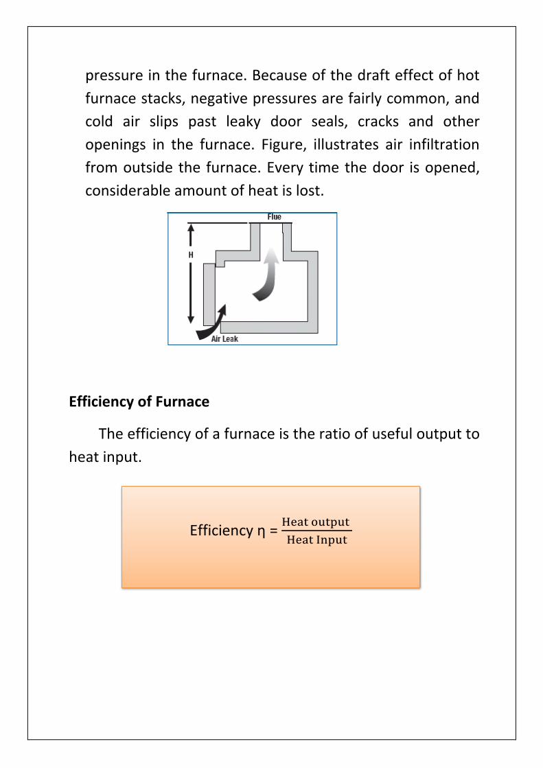
Air Infiltration - Excess air does not necessarily enter the
furnace as part of the combustion air supply. It can also
infiltrate from the surrounding room if there is a negative
pressure in the furnace. Because of the draft effect of hot
furnace stacks, negative pressures are fairly common, and
cold air slips past leaky door seals, cracks and other
openings in the furnace. Figure, illustrates air infiltration
from outside the furnace. Every time the door is opened,
considerable amount of heat is lost.
Efficiency of Furnace
The efficiency of a furnace is the ratio of useful output to
heat input.
Efficiency ƞ = Heat output
Heat Input

The furnace efficiency can be determined by both direct
and indirect method.
Direct Method
The efficiency of furnace can be judged by measuring
the amount of fuel needed per unit weight of material.
The quantity of heat to be imparted (Qout) to the stock can be
found from
Indirect Method
Similar to the method of evaluating boiler efficiency by
indirect method, furnace efficiency can also be calculated by
indirect methods. Furnace efficiency is calculated after
subtracting sensible heat loss in flue gas, loss due to moisture
in flue gas, heat loss due to openings in furnace, heat loss
through furnace skin and other unaccounted losses.
Qout = MS x Cps (TD – TC)

In order to find out furnace efficiency using indirect
method, various parameters that are required are hourly
furnace oil consumption, material output, excess air quantity,
temperature of flue gas, temperature of furnace at various
zones, skin temperature and hot combustion air temperature.
Instruments like infrared thermometer, fuel efficiency
monitor, surface thermocouple and other measuring devices
are required to measure the above parameters.
Heat lost through Flue gases, HF = VFG x CPFG (TFG-TS)
Heat lost through ICW, HW = VCW x ρW x CPW x ∆TCW
Heat lost through radiation from doors, HR = 4.96E x
[(TO+273/100)4 – (TS+273/100)4] x A x dt
Heat lost through radiation and convection, HRC = AS x a x
(TEW – TS)1.25 + 4.88E x [(TEW+273/100)4 – (TS+273/100)4]
Heat lost through moisture in Air, HMA = Actual mass of air
x Humidity factor x Specific Heat x Temperature diff.
Heat lost through moisture in Gas, HMG = Moisture in Gas x
Specific Heat x Temperature diff.

Notations – Ms – Mass of Stock heated Cps – Specific Heat of Bloom material TD – Bloom Discharging Temperature TS – Ambient Temperature VFG – Volume of Flue gases CPFG – Specific Heat of Flue gases TFG – Flue gas furnae exit Temperature VCW – Volume of ICW supplied CPW – Specific Heat of Water ∆TCW – Rise in temperature of ICW TO – Temperature of opening door A – Area of the opening door dt – Opening time of the doors AS – Area of Surface TEW – Furnace External wall temperature
Loss Percentages
HF% = 𝐇𝐅 𝐱 𝟏𝟎𝟎
𝐂𝐕 𝐨𝐟 𝐅𝐮𝐞𝐥
HW% = 𝐇𝐖 𝐱 𝟏𝟎𝟎
𝐂𝐕 𝐨𝐟 𝐅𝐮𝐞𝐥 𝐱 𝐆𝐚𝐬 𝐅𝐥𝐨𝐰
HR% = 𝐇𝐑 𝐱 𝟏𝟎𝟎
𝐂𝐕 𝐨𝐟 𝐅𝐮𝐞𝐥 𝐱 𝐆𝐚𝐬 𝐅𝐥𝐨𝐰
HRC% = 𝐇𝐑𝐂 𝐱 𝟏𝟎𝟎
𝐂𝐕 𝐨𝐟 𝐅𝐮𝐞𝐥 𝐱 𝐆𝐚𝐬 𝐅𝐥𝐨𝐰
HMA% = 𝐇𝐌𝐀 𝐱 𝟏𝟎𝟎
𝐂𝐕 𝐨𝐟 𝐅𝐮𝐞𝐥
HMG% = 𝐇𝐌𝐆 𝐱 𝟏𝟎𝟎
𝐂𝐕 𝐨𝐟 𝐅𝐮𝐞𝐥
Furnace Thermal Efficiency, ƞ = 100 – HF% - HW% - HR% -
HRC% - HMA% - HMG%

OBSERVATIONS
PARAMETERS UNITS FURNACE 1 FURNACE 2
TOTAL GAS FLOW m3/h 5618 5291 5254 5214 9658 9693 9973 9983
TOTAL AIR FLOW m3/h 16952 16956 17047 16857 27943 27712 28383 28768
MIXED GAS CV Kcal/m3 2362 2364 2345 2355 2346 2373 2392 2413
NUMBER OF BLOOMS HEATED
93 93 93 93 87 87 87 87
BLOOMS ROLLED 27 28 27 26 39 40 40 41
MASS OF EACH BLOOM Ton 2.67 2.67 2.67 2.67 2.67 2.67 2.67 2.67
BLOOM DISCHARGING TEMPERATURE
OC 1174 1173 1175 1174 1177 1178 1180 1181
BLOOM CHARGING TEMPERATURE
OC 33 33 33 33 33 33 33 33
FLUE GAS EXIT TEMPERATURE
OC 541 540.4 541 540.4 542.3 543 543.7 544.3
AMBIENT TEMPERATURE OC 33 33 33 33 33 33 33 33
VOLUME OF ICW SUPPLIED
m3/h 68.83 69.21 69.02 68.88 57.75 58.23 59.10 59.09
PRESSURE RISE IN ICW bar 4.22 4.21 4.18 4.19 4.3 4.29 4.29 4.27
OPENING TIME OF DOORS (CHARGING & DISCHARGING)
h 1.11 1.11 1.11 1.11 1.04 1.04 1.04 1.04
CHARGING DOORS TEMPERATURE
OC 80 80 80 80 80 80 80 80
DISCHARGING DOORS TEMPERATURE
OC 90 90 90 90 90 90 90 90
FURNACE EXTERNAL WALL TEMPERATURE
OC 45 45 45 45 45 45 45 45
MOISTURE IN FUEL GAS m3/h 2.97 2.97 2.97 2.97 2.97 2.97 2.97 2.97

SPECIFIC HEAT OF FLUE GAS – 0.3 kcal/m3-oC
SPECIFIC HEAT OF FUEL GAS – 0.3 kcal/m3-oC
SPECIFIC HEAT OF AIR – 0.3 kcal/m3-oC
SPECIFIC HEAT OF BLOOM – 0.165 kcal/m3-oC
DENSITY OF AIR – 1.27 kg/m3
SPECIFIC HEAT OF WATER – 1 kcal/kg-oC
HUMIDITY FACTOR OF AIR – 0.654
CHARGING DOOR AREA – 6.7m x 0.77m x 2 Doors
DISCHARGING DOOR AREA – 6.7m x 1.2m x 2 Doors
ROOF AREA – 282 m2
HEARTH AREA – 282 m2
SIDE WALL AREA ( MILL SIDE & BSY SIDE ) – 182 m2
DENSITY OF WATER – 1000 kg/m3

CALCULATIONS
PARAMETER UNITS FURNACE 1 FURNACE 2
Heat given by Fuel Gas
Mcal/h 12593.72 23402.41
Heat due to oxidation
Mcal/h 6704.1 6272.1
Heat in the material
Mcal/h 13572.02 20194.81
Heat lost through Flue gas
Mcal/h 3396.09 5821.74
Heat lost to ICW Mcal/h 100.94 87.50
Heat lost through doors due to radiation (Charging & Discharging)
Mcal/h 9.07 8.58
Heat lost through walls of furnace due to radiation and convection
Mcal/h 45.19 45.19
Heat lost to moisture in air
Mcal/h 1861.62 3115.10
Heat lost to moisture in Fuel Gas
kcal/h 303.56 305.88

HEAT BALANCE SHEET
Furnace 1
INPUT OUTPUT
Description Value (Mcal/h) Description Value (Mcal/h)
Percent %
Heat given by Fuel Gas
12593.72 Heat in the material
13572.02 70.33%
Heat due to oxidation
6704.1 Heat lost through Flue gas
3396.09 17.59%
Heat lost to ICW 100.94 0.52%
Heat lost through doors due to radiation (Charging & Discharging)
9.07 0.04%
Heat lost through walls of furnace due to radiation and convection
45.19 0.23%
Heat lost to moisture in air
1861.62 9.49%
Heat lost to moisture in Fuel Gas
303.56 1.54%
Unaccounted losses
9.33 0.04%
Total 19297.82 Total 19297.82 100%
Thermal Efficiency of the Furnace = 70.33% (Direct Method)
= 70.55% (Indirect Method)

Furnace 2
INPUT OUTPUT
Description Value (Mcal/h) Description Value (Mcal/h)
Percent %
Heat given by Fuel Gas
23402.41 Heat in the material
20194.81 68.05%
Heat due to oxidation
6272.1 Heat lost through Flue gas
5821.74 19.62%
Heat lost to ICW 87.50 0.29%
Heat lost through doors due to radiation (Charging & Discharging)
8.58 0.03%
Heat lost through walls of furnace due to radiation and convection
45.19 0.23%
Heat lost to moisture in air
3115.10 10.49%
Heat lost to moisture in Fuel Gas
305.88 1.03%
Unaccounted losses
95.71 0.32%
Total 29674.51 Total 29674.51 100%
Thermal Efficiency of the Furnace = 68.05% (Direct Method)
= 67.99% (Indirect Method)
CONCLUSION
The present efficiency of furnace in terms of
performance is more than satisfactory. There are many
potions for increasing the energy efficiency.
Employing air –gas ratio control technology and
regenerative burner is the most effective way to increase
efficiency in most furnaces. To fight the challenges of rising
energy cost and environmental regulations, a close co-
operation of the end user, the furnace builder and the burner
manufacture is necessary to choose the best possible
configuration with respect to -
Performance Energy efficiency
Low emissions
Low Maintenance
Not higher than needed investment costs.
We formed furnace efficiency with waste heat recovery
system is very much more compare to actual furnace
efficiency. By following the above action with upcoming
technologies the furnace efficiency can be increases further
more. Efficiency increase measure nothing but fuel saving
fuel save means energy saving, we can turned it as revenue
saving.
Due to technological obsolescence and the high rate of up
gradation the availability of spares and its associated techno

economics influence the running of the system. In such cases
sustaining an old system economically is not feasible and up
gradation to an updated system is not a matter of choice but
a matter of choice but a matter of consumption.