report lh2 target vessel - indiana.edulh2targ/losalamosfiles/safety documentation/ares... · 2...
TRANSCRIPT

DRAFT
STRUCTURAL ANALYSIS OF THE LH2 TARGET VESSEL FOR THE NPDGAMMA EXPERIMENT
Prepared for
Los Alamos National Laboratory Contract No. 008937-000-00CX / Task No. 26
Report No. 0001579.26-001 Revision 0
October 31, 2001
Prepared by
ARES CORPORATION
555 Oppenheimer Drive, Suite 102 Los Alamos, New Mexico 87544

Structural Analysis of the LH2 Target Vessel Report No. 0001579.26-001, Rev. 0 for the NPDGamma Experiment October 31, 2001
ARES DRAFT Page i CORPORATION
STRUCTURAL ANALYSIS OF THE LH2 TARGET VESSEL FOR THE NPDGAMMA EXPERIMENT
Prepared for
Los Alamos National Laboratory Contract No. 008937-000-00CX / Task No. 26
Report No. 0001579.26-001-001 Revision 0
October 31, 2001
Prepared by: F.D. Michaud, P.E.
Approved by: _______________________
Darrell H. Bultman, P.E. Date: _____________________________

Structural Analysis of the LH2 Target Vessel Report No. 0001579.26-001, Rev. 0 for the NPDGamma Experiment October 31, 2001
ARES DRAFT Page ii CORPORATION
Table of Contents
1.0 INTRODUCTION .......................................................................................................................... 1
2.0 GENERAL DESCRIPTION........................................................................................................... 1
3.0 MODELS ........................................................................................................................................ 4
4.0 FAILURE CRITERIA .................................................................................................................... 7
5.0 ANALYSIS RESULTS .................................................................................................................. 7
6.0 ALTERNATIVES......................................................................................................................... 13
7.0 CONCLUSION............................................................................................................................. 14
8.0 RECOMMENDATIONS.............................................................................................................. 15
9.0 REFERENCES ............................................................................................................................. 17
Figures
Figure 1. Vessel entrance end. ....................................................................................................................2 Figure 2. Vessel exit end............................................................................................................................ 2 Figure 3. Axisymmetric finite element model of magnesium head and partial shell. ............................... 4 Figure 4. Axisymmetric finite element model of exit head and annulus plate. .......................................... 5 Figure 5. Three-dimensional finite element model of exit end................................................................... 6 Figure 6. Stress intensities in forward half of vessel for 85-psi internal pressure. ..................................... 9 Figure 7. Stress distributions in ellipsoidal head for various aspect ratios. ............................................. 10 Figure 8. Stress intensities in exit end of vessel for 85-psi internal pressure. .......................................... 11 Figure 9. Detail of stress intensities in exit end of vessel for 85-psi internal pressure............................. 12 Figure 10. Stress intensities for alternative design with convex ellipsoidal head; 85-psi internal pressure.
........................................................................................................................................................... 13 Figure 11. Stress intensities for alternative design with concave ellipsoidal head; 85-psi internal
pressure. ............................................................................................................................................ 14
Tables Table 1. Vessel primary dimensions [3, 4]. ................................................................................................ 3 Table 2. Vessel material mechanical properties (at room temperature). .................................................... 3 Table 3. Vessel parameters derived from Division 2 [2]. ........................................................................... 8

Structural Analysis of the LH2 Target Vessel Report No. 0001579.26-001, Rev. 0 for the NPDGamma Experiment October 31, 2001
ARES DRAFT Page 1 CORPORATION
1.0 INTRODUCTION
This report discusses the static stress analysis of a cryogen target vessel for the NPDGamma experiment on flight path 12 at the Manuel Lujan Neutron Scattering Center (MLNSC). During normal operation the vessel will contain approximately 20 liters of liquid para-hydrogen at 17K. Because of potential hazards in using hydrogen, and the need to satisfy all MLNSC operational and safety requirements while achieving experimental goals, the Technical Review Committee has recommended a complete structural analysis of the vessel [1]. ARES Corporation under LANL Contract No. 008937-000-00CX performed the analysis. As recommended by the Committee, and to the greatest extent practical, the vessel design was analyzed in accordance with the ASME Boiler and Pressure Vessel Code, Sections II and VIII, 1998 [2]. Division 2 of the Code rather than Division 1, was used because the latter merely specifies the wall thickness necessary to limit the basic circumferential stress to the allowable tabulated stress. Safety factors and design rules in Division 1 allow for larger, more localized stresses, which occur at geometric discontinuities in vessels such as the target vessel. Division 2, on the other hand, requires a detailed evaluation of the stresses and may provide greater latitude in stress levels. Application of the Code in this analysis is limited to the aluminum portion of the vessel because magnesium alloys are not code-approved and, therefore, are not covered by Section II. Detailed analyses of the entire vessel were performed largely with the COSMOS/M® numerical code, a commercial finite element program. Results of the finite element solutions were verified with widely published analytical methods for pressure vessel applications, where practical. 2.0 GENERAL DESCRIPTION The vessel design prepared by the Indiana University (IU) team consists of an aluminum alloy cylindrical shell with an integral ellipsoidal head welded at the exit end, and a magnesium alloy ellipsoidal head bolted to the entrance end. Fill and vent lines extend from a flat annulus plate, which spans the radial space between the exit head skirt and the cylindrical shell. Entrance and exit ends of the vessel are shown in Figures 1 and 2, respectively. It is assumed that all joints connecting the fill and vent lines, annulus plate, exit head, cylindrical shell, and flanged neck at the entrance end, are made with full penetration welds. The flanged ellipsoidal head at the entrance end is assumed to be a single machined part. Primary dimensions of the vessel are given in Table 1. These and other dimensions defining the flanged neck, as well as locations and sizes of the fill and vent penetrations are taken from various documents provided by IU personnel [3,4].

Structural Analysis of the LH2 Target Vessel Report No. 0001579.26-001, Rev. 0 for the NPDGamma Experiment October 31, 2001
ARES DRAFT Page 2 CORPORATION
Figure 1. Vessel entrance end.
Figure 2. Vessel exit end.
Magnesium head
Cylindrical shell
Neck
Fill line
Vent line Exit head
Annulus plate

Structural Analysis of the LH2 Target Vessel Report No. 0001579.26-001, Rev. 0 for the NPDGamma Experiment October 31, 2001
ARES DRAFT Page 3 CORPORATION
Mechanical properties of the vessel materials are given in Table 2. Although the tabulated values are for room temperature it is important to note that the modulus of elasticity and tensile yield strength of the aluminum alloy increase by about 15% and 25%, respectively, at the target operating temperature [6,7]. Moreover, fatigue strength of 5083-0 aluminum weldments made with 5556 filler alloy may be more than 20% greater at low temperatures than at room temperature [6,7]. Room temperature compressive yield strength of the aluminum alloy is about equal to the tensile yield strength. A literature search for similar low temperature properties, specifically for AZ31B magnesium alloy in the H24 condition (hard rolled), failed to yield any useful information. However, other data for this alloy in the 0 condition (annealed) show an increase of almost 50% in yield strength at a temperature of 20K [8]. Room temperature compressive yield strength of AZ31B-H24 is 26 ksi.
Table 1. Vessel primary dimensions [3, 4].
Dimension Entrance Head (in.) Cylindrical Shell (in.) Exit Head (in.) Inside radius 5.125 5.900 4.225 Thickness (wall) 0.125 0.100 0.150 Height (inside) 2.175 N/A 1.625 Effective length N/A 9.750 N/A Thickness (annular ring)
N/A N/A 0.250
Table 2. Vessel material mechanical properties (at room temperature).
Component Material and Condition
[4]
Modulus of Elasticity (psi)
[5]
Poisson’s Ratio
[5]
Yield Strength, 0.2% offset
(ksi) [5]
Entrance head Magnesium alloy
AZ31B-H24 6.5 x 10⁶ 0.35 32.0
Cylindrical shell w/neck & flange
Aluminum alloy 5083-0
10 x 106 0.33 21.0
Exit head w/annulus plate
Aluminum alloy 5083-0
10 x 106 0.33 21.0

Structural Analysis of the LH2 Target Vessel Report No. 0001579.26-001, Rev. 0 for the NPDGamma Experiment October 31, 2001
ARES DRAFT Page 4 CORPORATION
The design internal pressure is taken as 85 psia, with atmospheric pressure as one standard atmosphere (14.7 psia), rather than the reduced pressure (11.2 psia) at the Los Alamos elevation [4]. The standard atmosphere is preferred for pressure vessel analyses. The design external pressure is taken as 30 psi, or about two standard atmospheres [4].
3.0 MODELS
With exception of the fill and vent line penetrations at its exit end, the vessel is axially symmetric, which allows the use of simpler, but more accurate finite element models for the calculation of stresses and deformations. Figure 3 is an axisymmetric finite element model of the forward half of the vessel extending from a transverse plane at the cylindrical shell’s midsection. Because the midsection is some distance from irregular features that give rise to greater stress gradients, such as the neck region of the shell and magnesium head, symmetry boundary conditions that reduce the size of the model are applied at the shell midsection. The same modeling method is used to study the behavior of the exit end at locations removed from the fill and vent penetrations.
Figure 3. Axisymmetric finite element model of magnesium head and partial shell.
Magnesium head
Neck
Cylindrical shell

Structural Analysis of the LH2 Target Vessel Report No. 0001579.26-001, Rev. 0 for the NPDGamma Experiment October 31, 2001
ARES DRAFT Page 5 CORPORATION
In Figure 3 the connectivity between the magnesium head flange and the shell flange is not continuous across the interface. A gap is created between the flanges to simulate the extent of joint clamping provided by the cylindrical shim through which the bolt passes. The root of the gap is aligned radially with the periphery of the cylindrical shim, thus preventing the interface from behaving as two rigidly connected bodies over the entire radial extent of the joint. An axisymmetric model of the exit end of the vessel extending from the shell midsection is shown in Figure 4. Even though asymmetry exists at this end of the vessel, the axisymmetric model is valid for evaluating the structure at discontinuities such as the junctions between the exit head skirt, annulus plate, and cylindrical shell at locations removed from the fill and vent penetrations. The model is valid for evaluating the ellipsoidal head as well.
Figure 4. Axisymmetric finite element model of exit head and annulus plate.
A full three-dimensional model of the exit end is shown in Figure 5. This model is used primarily for the evaluation of discontinuities in the vicinity of the fill and vent line penetrations. Only short portions of the lines are represented in order to simulate any local stiffening of the annulus plate directly attributable to the tube walls. Because this model uses a different type of finite element than the axisymmetric models, it is also used to validate results of the latter. Widely published analytical
Exit head
Annulus plate
Cylindrical shell

Structural Analysis of the LH2 Target Vessel Report No. 0001579.26-001, Rev. 0 for the NPDGamma Experiment October 31, 2001
ARES DRAFT Page 6 CORPORATION
solutions for various pressure vessel components and shapes are used in conjunction with the different types of models and finite elements to verify results.
Figure 5. Three-dimensional finite element model of exit end.
Little information about the vessel support method was provided, so it was necessary to make two assumptions. Because it is common practice to support cryogen vessels in a non-rigid, or compliant manner to minimize localized stresses due to differential contractions, it is assumed that external forces and moments imparted to the vessel shell by supports are negligible compared to the internal forces and moments created by the applied pressures. Reaction forces and moments at support points or connections due to vessel and liquid weights are also not accounted for in the analysis. In short, the vessel is modeled as a body subject only to internal and external pressures, and capable of axial and radial deformations unrestrained by external forces and moments.

Structural Analysis of the LH2 Target Vessel Report No. 0001579.26-001, Rev. 0 for the NPDGamma Experiment October 31, 2001
ARES DRAFT Page 7 CORPORATION
4.0 FAILURE CRITERIA The most commonly applied failure criteria in steady state structural analyses are the maximum stress theory, the von Mises distortion energy criterion, and the maximum shear stress, or Tresca theory. Division 2 of the ASME Boiler and Pressure Vessel Code subscribes to the last of these because it is the most conservative of the three, and it is the simplest to apply. State of stress in a body may be completely defined by the magnitudes and directions of the three orthogonal principal stresses. The maximum shear stress theory, which applies specifically to ductile materials, postulates that yielding in a body subject to combined stresses will occur when the resulting maximum shear stress is equal to the maximum shear stress at the yield point in a simple tension test. Maximum shear stress in a body is equal to half the difference of the algebraic maximum and minimum principal stresses at that point. In a simple tension specimen, the maximum shear stress is equal to half the normal stress at yielding. Results of finite element solutions are typically given in terms of stress intensity, which is twice the maximum shear stress. Determination of the maximum stress intensities and their locations in the structure for the specified pressure conditions is the focus of the analysis. To determine suitability of the design, the calculated intensities are compared with the maximum stress intensity allowed by the Code for the given material. Although the Code does not cover AZ31B-H24 magnesium alloy, it is reasonable to assume that suitability of the design and material selection may be determined based on the same failure criterion, if a conservative maximum allowable stress intensity of 50% of yield strength is used. Based on the yield strength given in Table 2, the maximum allowable stress intensity applied to the magnesium head is 16.0 ksi. This rationale is consistent with the criteria for establishing design stress intensity values prescribed in Appendix 2, Section II, Part D of the Code. Stress intensity values for nonferrous wrought materials may be based on 66% of minimum yield strength at room temperature, according to that appendix. In Section II, Part D of the Code, the design stress intensity value for aluminum alloy 5083-0 is 12.0 ksi. According to Division 2 rules, this value may be increased by a factor of 1.5 for stress intensities based on combinations of stress components that include primary membrane, local membrane, and primary bending stresses; therefore, the maximum allowable stress intensity used in the analysis is 18.0 ksi. 5.0 ANALYSIS RESULTS The initial step in determining the suitability of the design for this application requires an evaluation of wall thicknesses and allowable pressures for both internal and external pressure cases according to Section VIII, Division 2 of the Code. Results of these calculations are summarized in Table 3. Minimum thicknesses for the entrance head and cylindrical shell are calculated for the design internal pressure of 85 psi. Because the internal pressure is applied to the convex surface of the exit head, a maximum allowable pressure is calculated for the head design thickness of 0.150-in. For the external pressure case the pressure is applied to the concave surface of the exit head, and a minimum thickness is calculated for a 30-psi applied pressure. The maximum allowable external pressure

Structural Analysis of the LH2 Target Vessel Report No. 0001579.26-001, Rev. 0 for the NPDGamma Experiment October 31, 2001
ARES DRAFT Page 8 CORPORATION
calculated for the cylindrical shell is based on its design wall thickness. Bracketed data in the table are design values. Because the Code does not cover ellipsoidal heads having aspect ratios greater than 2:1 the tabulated values for the entrance head minimum thickness (internal pressure case), and the exit head minimum thickness (external pressure case) are, at best, only estimates. The aspect ratio, which is approximately 2.3:1 for both ellipsoidal heads, is defined as the ratio of the semi-major and semi-minor axis lengths. A minimum thickness for the entrance head cannot be estimated for the external pressure case because the calculation requires factors derived from data curves for specific materials. Such curves do not exist for materials not covered by the Code.
Table 3. Vessel parameters derived from Division 2 [2].
Internal Pressure Case External Pressure Case Component Min.
Thickness (in.)
Max. Allow. Pressure
(psi)
Min. Thickness
(in.)
Max. Allow. Pressure (psi)
Entrance Head
0.048 {0.125}* N/A
Cylindrical Shell
0.042 {0.100} 80.0 {30}
Exit Head 93.5 {85} 0.015 {0.150}
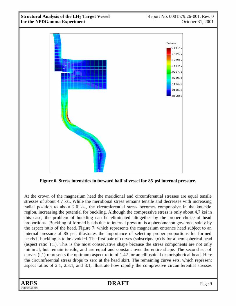
*Bracketed data are design values. More detailed analyses are needed to define stress intensity levels and distributions in critical regions of the vessel because the data in Table 3 simply indicate the adequacy of the design wall thicknesses for the applied pressures. Figure 6 is a plot of stress intensities in the forward half of the vessel subject to an internal pressure of 85 psi. The plot clearly shows that, with the exception of the neck region, stress intensities throughout this end of the vessel are well below the maximum allowable stress intensity of 18 ksi. Stress intensities at the base of the neck, however, range from 16.5 ksi (max) at the outer fiber, to 12.1 ksi (min) at the innermost fiber. Decreasing the slope of the shoulder and increasing the radius between the shoulder and neck will likely reduce these stresses.
Structural Analysis of the LH2 Target Vessel Report No. 0001579.26-001, Rev. 0 for the NPDGamma Experiment October 31, 2001
ARES DRAFT Page 9 CORPORATION
Figure 6. Stress intensities in forward half of vessel for 85-psi internal pressure.
At the crown of the magnesium head the meridional and circumferential stresses are equal tensile stresses of about 4.7 ksi. While the meridional stress remains tensile and decreases with increasing radial position to about 2.0 ksi, the circumferential stress becomes compressive in the knuckle region, increasing the potential for buckling. Although the compressive stress is only about 4.7 ksi in this case, the problem of buckling can be eliminated altogether by the proper choice of head proportions. Buckling of formed heads due to internal pressure is a phenomenon governed solely by the aspect ratio of the head. Figure 7, which represents the magnesium entrance head subject to an internal pressure of 85 psi, illustrates the importance of selecting proper proportions for formed heads if buckling is to be avoided. The first pair of curves (subscripts i,o) is for a hemispherical head (aspect ratio 1:1). This is the most conservative shape because the stress components are not only minimal, but remain tensile, and are equal and constant over the entire shape. The second set of curves (i,1) represents the optimum aspect ratio of 1.42 for an ellipsoidal or torispherical head. Here the circumferential stress drops to zero at the head skirt. The remaining curve sets, which represent aspect ratios of 2:1, 2.3:1, and 3:1, illustrate how rapidly the compressive circumferential stresses

Structural Analysis of the LH2 Target Vessel Report No. 0001579.26-001, Rev. 0 for the NPDGamma Experiment October 31, 2001
ARES DRAFT Page 10 CORPORATION
increase in magnitude with decreasing head depth. Some structural codes limit the aspect ratio of ellipsoidal and torispherical heads to 2:1.
Figure 7. Stress distributions in ellipsoidal head for various aspect ratios.
For the bulk of the cylindrical shell, with 85-psi internal pressure applied, the meridional and circumferential stresses are 2.5 ksi and 5.1 ksi, respectively. Maximum radial dilation of the shell is less than 0.003 in., and the maximum axial expansion of the magnesium head is about 0.016-in. These stresses and displacements, as well as the stresses in the ellipsoidal head are readily verified with analytical solutions. With the exception of the neck region, stress intensity over much of the entrance end of the vessel is 2.0 ksi, or less, when the vessel is subject to a 30.0-psi external pressure. Across the shell wall at the base of the neck, the stress intensity ranges from about 5.8 ksi to 4.4 ksi, with the maximum occurring in the outermost fiber, as for internal pressure. The maximum allowable external pressure based on the thickness of the wall and other neck parameters is about 100 psi, according to Division 2 rules for a conical transition. Maximum axial displacement at the crown of the magnesium head is less than 0.006-in.
0 1 2 3 4 5 61.4 .104
1.2 .104
1 .104
8000
6000
4000
2000
0
2000
4000
6000
Radial position (in.)
Stre
ss (p
si)
σ1i 0,
σ2i 0,
σ1i 1,
σ2i 1,
σ1i 2,
σ2i 2,
σ1i 3,
σ2i 3,
σ1i 4,
σ2i 4,
xi

Structural Analysis of the LH2 Target Vessel Report No. 0001579.26-001, Rev. 0 for the NPDGamma Experiment October 31, 2001
ARES DRAFT Page 11 CORPORATION
Whereas the stresses resulting from either internal or external pressure loading on the entrance end of the vessel are less than the maximum allowable stress intensity, stresses in regions of the exit end far exceed this limit for the internal pressure case. Pronounced discontinuities, such as the junctures of the flat annulus plate with the cylindrical shell and ellipsoidal head, give rise to large, highly localized stresses. Figure 8 shows the general distribution of stress intensities on the inner and outer peripheries of the exit end near these junctures. The limited extent of the perturbation in these stress patterns because of the fill and vent line penetrations in the annulus plate is apparent.
Figure 8. Stress intensities in exit end of vessel for 85-psi internal pressure.
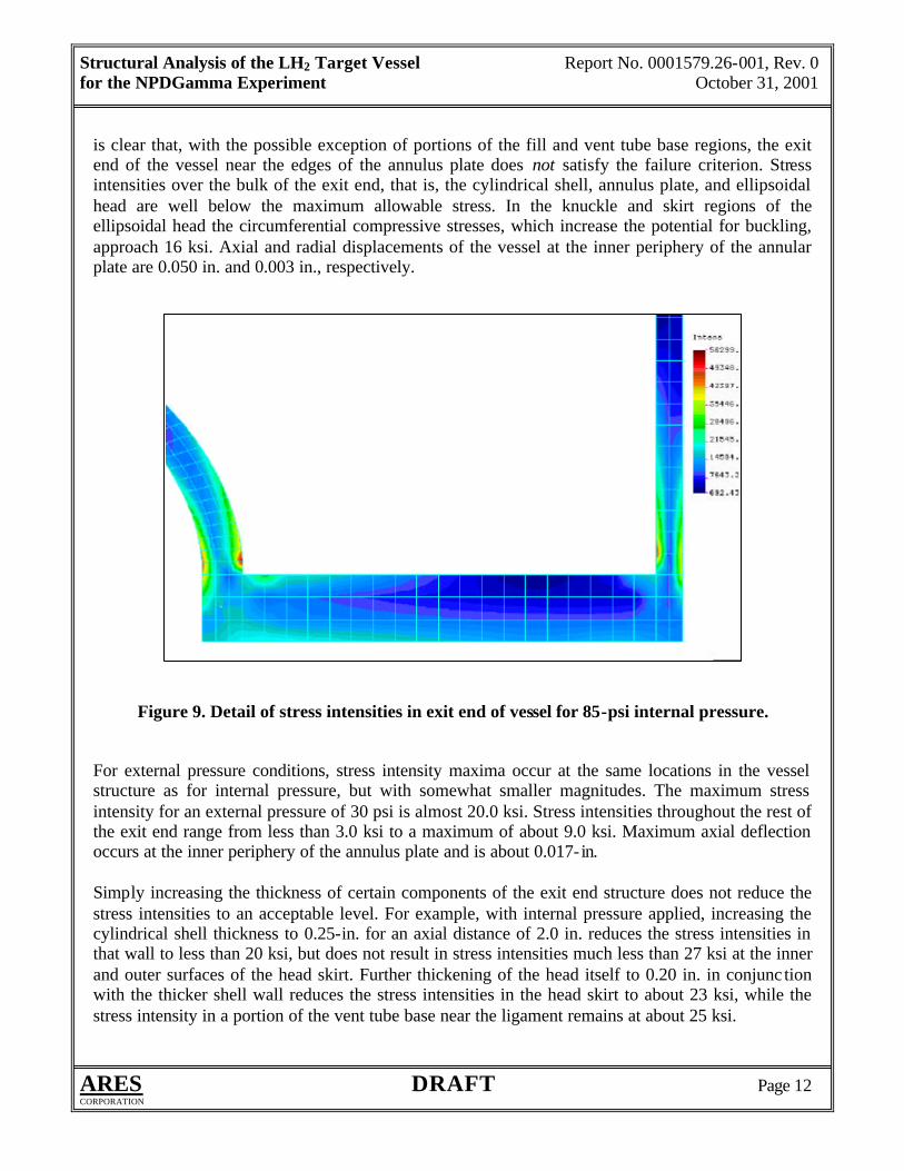
Greater detail of the stress distribution through the cylindrical shell and ellipsoidal head near the junctures is shown in the axisymmetric model of Figure 9. Stress intensities at the outer and inner fibers of the cylindrical shell are 41.5 ksi and 51.1 ksi, respectively. Similarly, stress intensities at the outer and inner fibers of the ellipsoidal head skirt are 47.6 ksi and 56.3 ksi, respectively. Around much of the base of both fill and vent tubes the stress intensity is about 17 ksi, but increases to more than 30 ksi in the ligaments between the tube wall and inner and outer edges of the annulus plate. It
Structural Analysis of the LH2 Target Vessel Report No. 0001579.26-001, Rev. 0 for the NPDGamma Experiment October 31, 2001
ARES DRAFT Page 12 CORPORATION
is clear that, with the possible exception of portions of the fill and vent tube base regions, the exit end of the vessel near the edges of the annulus plate does not satisfy the failure criterion. Stress intensities over the bulk of the exit end, that is, the cylindrical shell, annulus plate, and ellipsoidal head are well below the maximum allowable stress. In the knuckle and skirt regions of the ellipsoidal head the circumferential compressive stresses, which increase the potential for buckling, approach 16 ksi. Axial and radial displacements of the vessel at the inner periphery of the annular plate are 0.050 in. and 0.003 in., respectively.
Figure 9. Detail of stress intensities in exit end of vessel for 85-psi internal pressure.
For external pressure conditions, stress intensity maxima occur at the same locations in the vessel structure as for internal pressure, but with somewhat smaller magnitudes. The maximum stress intensity for an external pressure of 30 psi is almost 20.0 ksi. Stress intensities throughout the rest of the exit end range from less than 3.0 ksi to a maximum of about 9.0 ksi. Maximum axial deflection occurs at the inner periphery of the annulus plate and is about 0.017- in. Simply increasing the thickness of certain components of the exit end structure does not reduce the stress intensities to an acceptable level. For example, with internal pressure applied, increasing the cylindrical shell thickness to 0.25-in. for an axial distance of 2.0 in. reduces the stress intensities in that wall to less than 20 ksi, but does not result in stress intensities much less than 27 ksi at the inner and outer surfaces of the head skirt. Further thickening of the head itself to 0.20 in. in conjunc tion with the thicker shell wall reduces the stress intensities in the head skirt to about 23 ksi, while the stress intensity in a portion of the vent tube base near the ligament remains at about 25 ksi.

Structural Analysis of the LH2 Target Vessel Report No. 0001579.26-001, Rev. 0 for the NPDGamma Experiment October 31, 2001
ARES DRAFT Page 13 CORPORATION
6.0 ALTERNATIVES The excessive stresses discussed in the previous section are due largely to the flat annulus plate, which behaves much like a typical flat head on any pressure vessel. Flat head closures are generally undesirable in pressure vessel designs because they give rise to large discontinuity stresses. Advantages of ellipsoidal and torispherical heads are readily apparent when the resulting stresses for a given load condition are compared with those for a flat closure. Figure 10 shows the exit end of the vessel with a standard ellipsoidal head having the same aspect ratio as the other heads, but a thickness of only 0.10- in. For an internal pressure of 85 psi the stress intensity over the bulk of the entire downstream half of the vessel is less than 9 ksi. Only in the head knuckle region at the base of the vent tube does the stress intensity reach a maximum of about 13 ksi. Radial dilation of the head skirt is essentially the same as for the current design, but the maximum axial displacement of the head is only 0.014 in. compared to 0.050 in. for that design. For an external pressure of 30 psi, the stress intensity decreases to less than 2.6 ksi over the bulk of the exit end, with the maximum again occurring at the base of the vent tube, where it is about 4.8 ksi. Axial displacement of the head is less than 0.006-in.
Figure 10. Stress intensities for alternative design with convex ellipsoidal head; 85-psi internal
pressure.

Structural Analysis of the LH2 Target Vessel Report No. 0001579.26-001, Rev. 0 for the NPDGamma Experiment October 31, 2001
ARES DRAFT Page 14 CORPORATION
If the ellipsoidal head is inverted and its diameter expanded to the cylindrical shell as shown in Figure 11, the maximum stress intensity, which occurs at the juncture of the two, decreases to approximately 12 ksi. This is further confirmation that eliminating the flat annulus plate is necessary to reduce the stresses to acceptable levels if much thicker walls are unacceptable. Axial displacement of the head, which is only 0.10- in. thick, is less than 0.014 in. Maximum radial dilation occurs at the head and cylindrical shell juncture, and is approximately 0.004-in. For an external pressure of 30 psi the maximum stress intensity occurs at the head skirt and shell juncture, but is less than 5.0 ksi. Axial and radial displacement maxima are both less than 0.005- in.
Figure 11. Stress intensities for alternative design with concave ellipsoidal head; 85-psi internal pressure.
7.0 CONCLUSION Results of the analysis show that the cylindrical shell, transition neck, and entrance window flange mount of the aluminum alloy vessel satisfy the maximum shear stress criteria subscribed to by the Code [2], for both internal and external pressure conditions. It is also shown that the maximum stress intensity in the magnesium entrance head is only about 30% of a conservative maximum allowable stress based on the methodology prescribed by the Code for nonferrous metals. Even though the
Structural Analysis of the LH2 Target Vessel Report No. 0001579.26-001, Rev. 0 for the NPDGamma Experiment October 31, 2001
ARES DRAFT Page 15 CORPORATION
aspect ratio of the ellipsoidal magnesium head exceeds the maximum specified by some structural codes, including the ASME code, buckling of the head due to internal pressure is not expected because the maximum compressive stresses are less than 20% of the material’s compressive yield strength. Stresses in the head caused by external pressure are only about 12% of the maximum allowable stress intensity. In contrast, the exit head design does not satisfy the failure criterion for either pressure condition. It is shown by means of two alternative geometries that the excessive stresses are due largely to the placement of a flat plate member, with limited out-of-plane stiffness, between two inherently stiff shells. Stress intensities near the junctures of the plate with these shells exceed the maximum allowable stress intensity by factors near 3. The relatively large axial displacement of the plate’s inner periphery is a clear indication of how little axial stiffness it provides. It is also shown that merely increasing the thickness of the cylindrical shell and ellipsoidal head is not a solution to this problem, as are more efficient geometries that exclude flat members. 8.0 RECOMMENDATIONS The alternatives discussed in Section 6.0 clearly illustrate how geometry, rather than material mass, is fundamental to structural stiffness in this application. Both alternatives utilize simpler shapes with thinner walls, yet result in stresses that are a fraction of those predicted for the current design. Moreover, either alternative may be implemented without significant change in vessel capacity. Further improvements in the design may be realized if the exit head is fabricated as a monolithic part, rather than a weldment of several parts. Machining the exit end from a single thick plate not only eliminates weld joints in critical locations where stresses tend to be greater, but allows the joints that are necessary to be located and oriented for minimal stress. For example, consider the alternative design with the convex head. Because the vessel is relatively small it is very cost effective to machine the head with an integral length of cylindrical shell (e.g., 1.5-in. – 2.0- in.) and tube nozzles for attachment of the vent and fill lines. The weld joining the exit head to the main cylindrical shell body is then not only located away from any discontinuities that give rise to high stresses, but is oriented circumferentially, so the maximum stress across the joint is limited to about 2.6 ksi for the internal pressure condition. Similarly, the welds joining the vent and fill lines are located at the ends of the nozzles, away from discontinuities, and where maximum stresses across the joints are much less than 0.50 ksi for the same pressure condition. Compared to weldments, monolithic machined parts of aluminum alloys are not only very cost effective because of the reduced number of fabrication steps, but are generally of better quality. Weldments typically require initial machining of parts followed by welding, thermal stress reliefs, and quite possibly some intermediate machining for fit up of parts joined in subsequent welding operations. Monolithic parts, on the other hand, may require only an intermediate thermal stress relief before the final machining operation. This method also allows incorporation of fillets in critical areas such as the bases of the vent and fill nozzles. A more subtle advantage of the machined part becomes apparent if intermediate machining of a weldment is necessary, especially in the region of a subsequent weld joint. An example of this in the current design is the intersection region of the

Structural Analysis of the LH2 Target Vessel Report No. 0001579.26-001, Rev. 0 for the NPDGamma Experiment October 31, 2001
ARES DRAFT Page 16 CORPORATION
vent line, annular plate, and cylindrical shell where a very thin ligament may exist. This arrangement may require layering of weld beads with some intermediate machining. If the vessel is fabricated to the standards of quality vacuum vessels, and leak checked accordingly, machining of the weld joints is not recommended because the vacuum integrity of the joint depends on the continuity of the weld skin, not the porous underlying body of the bead. In summary, it is recommended that the current exit end design of the vessel be replaced with one of the suggested alternatives or some variation thereof.

Structural Analysis of the LH2 Target Vessel Report No. 0001579.26-001, Rev. 0 for the NPDGamma Experiment October 31, 2001
ARES DRAFT Page 17 CORPORATION
9.0 REFERENCES
1. Final Report. Preliminary Conceptual Design Review of the NPDGamma Experiment Hydrogen Target at the Manuel Lujan Scattering Center (LANSCE-12). March 12, 2001. Los Alamos National Laboratory.
2. ASME Boiler and Pressure Vessel Code, Rules for Construction of Pressure Vessels, Section
VIII, Division 2 – Alternative Rules. 1998 edition.
3. Indiana University drawing of liquid hydrogen vessel, latest revision as of Sept. 18, 2001. No drawing number available.
4. Personal correspondence, e-mail, Snow, M., Indiana University. Excerpts from latest revision,
NPDGamma Liquid Hydrogen Engineering Document, Sept. 18, 2001. 5. ASM Metals Handbook, Vol. 1, Properties and Selection of Metals, 8th Edition. 6. ALCOA Aluminum publication Aluminum, the Cryogenic Metal. 7. Cryogen Materials Data Handbook, Martin Marietta Corporation, 1966. 8. Reed, R.P., et al, Some Mechanical Properties of Magnesium Alloys at Low Temperatures,
Advances in Cryogenic Engineering, Vol. 5, 1959.