report no. cg-d-12-97 phase i feasibility study: … no. cg-d-12-97 phase i feasibility study:...
TRANSCRIPT
Report No. CG-D-12-97
Phase I Feasibility Study:Seawater Hydraulic Transfer Pump
John Kunsemiller
Naval Facilities Engineering Service CenterPort Hueneme, CA 93043-4328
Final ReportNovember 1996
This document is available to the U.S. public througlttheNational Technical Information Service, Springfield, Virginia 22161
Prepared for:
U.S. Department of TransportationUnited States Coast GuardMarine Safety and Environmental Protection, (G-M)Washington, DC 20593-0001
and
U.S. Coast GuardResearch and Development Center1082 Shennecossett RoadGroton, CT 06340-6096

NOTICE
This document is disseminated under the sponsorship of theDepartment of Transportation in the interest of informationexchange. The United States Government assumes no liabilityfor its contents or use thereof.
The United States Government does not endorse products ormanufacturers. Trade or manufacturers' names appear hereinsolely because they are considered essential to the object ofthis report.
The contents of this report reflect the views of the Coast GuardResearch & Development Center. This report does not consti-tute a standard, specifica i.
S G:. IGubther
S~ Commanding Officer
United States Coast GuardResearch & Development Center1082 Shennecossett RoadGroton, CT 06340-6096
ii

Technical Report Documentation Page1. Report No. 2. Government Accession No. 3. Recipient's Catalog No.
CG-D-12-97
4. Title and Subtitle 5. Report DateNovember 1996
Phase I Feasibility Study: Seawater Hydraulic Transfer Pump 6. Performing Organization CodeProject Element No. 4120.3.1
7. Author(s) 8. Performing Organization Report No.
John Kunsemiller R&DC 34196
9. Performing Organization Name and Address 10. Work Unit No. (TRAIS)
v Naval Facilities Engineering Service Center 11. Contract or Grant No.Port Hueneme, CA 93043-4328
12. Sponsoring Agency Name and Address 13. Type of Report and Period CoveredFinal Report
U.S. Department of Transportation U.S. Coast GuardUnited States Coast Guard Research and Development Center 14. Sponsoring Agency CodeMarine Safety and Environmental 1082 Shennecossett Road Commandant (G-MOR)Protection (G-M) Groton, CT 06340-6096 U.S. Coast Guard HeadquartersWashington, DC 20593-0001 Washington, DC 20593-0001
15. Supplementary NotesThe R&D Center technical point of contact is Kenneth Bitting, 860-441-2733.
16. Abstract
The Naval Facilities Engineering Service Center (NFESC) has completed a Phase I feasibility study to determinewhether or not a seawater hydraulic design for the CCN-150 transfer pump system would reduce weight thereby makingthe system easier for U.S. Coast Guard (USCG) Strike Teams to deploy. The feasibility study included a review ofcommercially available seawater hydraulic system hardware applicable to this conversion and development of aseawater hydraulic transfer pump system design concept.
Based on results of the literature survey, concept development studies, and USCG National Strike Force operationalrequirements, it was determined that an open circuit seawater hydraulic system configuration of the transfer pumpsystem with a lightweight hydraulic power source can provide a 3,000-pound savings over the present oil hydraulicsystem powered by the MOD 6 hydraulic power source. A secondary benefit of this seawater hydraulic system isimproved system safety and environmental compliance through the elimination of hazardous hydraulic oil. Thesefindings support NFESC's recommendation to proceed with a Phase II demonstration of a seawater hydraulic poweredCCN-150 transfer pump.
It has also been determined that a reduction in transfer pump system weight and an improvement in pump performancecan be achieved without conversion to seawater hydraulic operation. Replacing the present wire braided reinforcedhydraulic hose with lighter weight thermoplastic hose can cut several hundred pounds off the system's weight. At thesame time, using a 1-inch diameter supply, a larger 1.25-inch diameter return, and 0.5-inch diameter case drain hosesizes will alleviate flow restrictions and improve power source efficiency. This will allow use of the lighter Duetz powersource for a significant weight savings over the now favored MOD 6 power source.
It became apparent during this investigation that other USCG hydraulic equipment such as skimmers and small pumpsmay be better candidates for conversion to seawater hydraulic operation. The application of seawater hydraulics to oilrecovery type equipment may be more advantageous because these systems are typically operated closer to the waterwhich would allow convenient access for seawater supply.
17. Key Words 18. Distribution Statement
oil spill equipment This document is available to the U.S. public throughseawater hydraulics the National Technical Information Service,transfer pumps Springfield, VA 22161.
19. Security Classif. (of this report) 20. SECURITY CLASSIF. (of this page) 21. No. of Pages 22. Price
UNCLASSIFIED UNCLASSIFIED
Form DOT F 1700.7 (8/72) Reproduction of form and completed page is authorized111i.

CD
C0 Aci cw) 4)0r, C
0 C In ,- -~2 m0CC LC ou ~ Lt. ~
*iZ It ~ l. N
E -0
U-. M, m~ N ~Co Co-C Co
Cm~- R-6 to ~ j Xq 0 O o0,i 6,. 'i COC ý C ýCi C jX -
0 0wC O- 0)
Z Nc
o 0 <-
0AM %Co~ oE~ 0, cE au .
WuE a E oT )EEC2 I 4IL. .0 EE 1 1N C0
C. E EEE tm a ~ 0:
OL C L O 6 EL EL E L E L Cm C4 LL L6 9~ 9 S t C ~ w
Cl))01111 lCd1! Ilolzl 111111 Et1111 at~l~ L1111 l6lllillll 11111 1111 911111
0 Is 8 7' 6 5 41 3 2 1 1 inches
O 0) "3 NYC n L-0 EE . E E EE- u I -E E 0
EE6l E EE)nC
E) 67u 1 .
-Z ECo EE E :
6 u rC.rE Cl, Er QC1(1 CmL :2EEE w
__I C A,
4- >1 CD In 2uu V , , C C
ou M C/ 00.4-< LL I.22 CC
> wC,)Q0 wI0
0c -1 V,2 I n nL
Q) an 0- >L4) t eE
E 0) C. Lu Cm0_r a Ci2Inr u C2 cc
o Wý
0 CuO
Inl N .L ~ I
< E 3, 0 9 E 0. 2=a sC
Cl)
iv
EXECUTIVE SUMMARY
The Naval Facilities Engineering Service Center (NFESC) has completed a Phase Ifeasibility study to determine whether or not a seawater hydraulic design for the CCN-150transfer pump system would reduce weight thereby making the system easier for U.S. CoastGuard (USCG) Strike Teams to deploy. The feasibility study included a review of commerciallyavailable seawater hydraulic system hardware applicable to this conversion and development of aseawater hydraulic transfer pump system design concept. Based on results of the literaturesurvey, concept development studies, and USCG National Strike Force operational requirements,it was determined that an open circuit seawater hydraulic system configuration of the transferpump system with a lightweight hydraulic power source can provide a 3,000-pound savings overthe present oil hydraulic system powered by the MOD 6 hydraulic power source. A secondarybenefit of this seawater hydraulic system is improved system safety and environmentalcompliance through the elimination of hazardous hydraulic oil. These findings support NFESC'srecommendation to proceed with a Phase II demonstration of a seawater hydraulic poweredCCN-150 transfer pump.
It has also been determined that a reduction in transfer pump system weight and animprovement in pump performance can be achieved without conversion to seawater hydraulicoperation. Replacing the present wire braided reinforced hydraulic hose with lighter weightthermoplastic hose can cut several hundred pounds off the system's weight. At the same time,using a 1-inch diameter supply, a larger 1.25-inch diameter return, and 0.5-inch diameter casedrain hose sizes will alleviate flow restrictions and improve power source efficiency. This willallow use of the lighter Duetz power source for a significant weight savings over the now favoredMOD 6 power source. It became apparent during this investigation that other USCG hydraulicequipment such as skimmers and small pumps may be better candidates for conversion toseawater hydraulic operation. The application of seawater hydraulics to oil recovery typeequipment may be more advantageous because these systems are typically operated closer to thewater which would allow convenient access for seawater supply.
ItV

(BLANK)
vi
CONTENTS
Page
INTRODUCTION ....................................... 1
BACKGROUND ........................................ 1
Component Description ................................ 2Requirements ....... .................................... 4
FINDINGS ............................................ 5
Motor Replacement 5..................................5Hydraulic Flow Restrictions . ............................. 7Hose Selection ..................................... 9Power Source Conversion ................................... 10Selection of a Prime Mover Pump .... ........................ 11Other Hydraulic Equipment ................................. 12
SYSTEM CONCEPTS ..................................... 13
Issues ........................................... 14
CONCLUSIONS ........................................ 16
RECOMMENDATIONS ................................... 17
REFERENCES ......................................... 18
APPENDIXES
A - Literature Survey Citations ........................... A-1B - Frenner Literature ................................. B-1C - Danfoss Literature ..................................... C-1D - Sources Sought .................................. D-1E - Hydraulic Hose Comparisons .......................... E-1
-vi,
vii

(BLANK)
viii
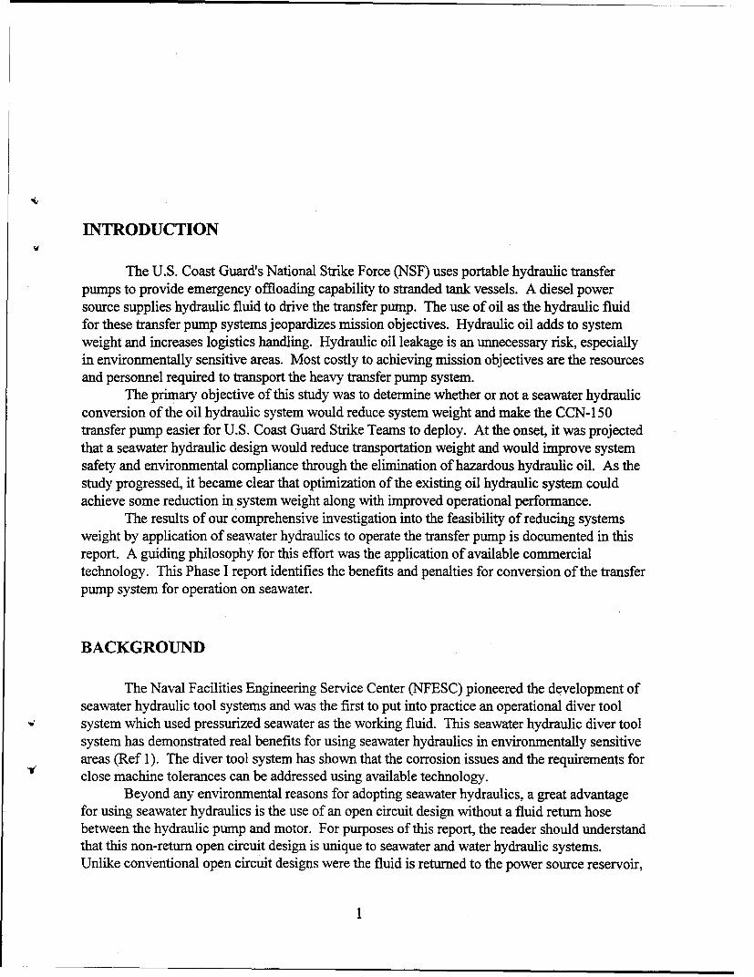
INTRODUCTION
The U.S. Coast Guard's National Strike Force (NSF) uses portable hydraulic transferpumps to provide emergency offloading capability to stranded tank vessels. A diesel powersource supplies hydraulic fluid to drive the transfer pump. The use of oil as the hydraulic fluidfor these transfer pump systems jeopardizes mission objectives. Hydraulic oil adds to systemweight and increases logistics handling. Hydraulic oil leakage is an unnecessary risk, especiallyin environmentally sensitive areas. Most costly to achieving mission objectives are the resourcesand personnel required to transport the heavy transfer pump system.
The primary objective of this study was to determine whether or not a seawater hydraulicconversion of the oil hydraulic system would reduce system weight and make the CCN-150transfer pump easier for U.S. Coast Guard Strike Teams to deploy. At the onset, it was projectedthat a seawater hydraulic design would reduce transportation weight and would improve systemsafety and environmental compliance through the elimination of hazardous hydraulic oil. As thestudy progressed, it became clear that optimization of the existing oil hydraulic system couldachieve some reduction in system weight along with improved operational performance.
The results of our comprehensive investigation into the feasibility of reducing systemsweight by application of seawater hydraulics to operate the transfer pump is documented in thisreport. A guiding philosophy for this effort was the application of available commercialtechnology. This Phase I report identifies the benefits and penalties for conversion of the transferpump system for operation on seawater.
BACKGROUND
The Naval Facilities Engineering Service Center (NFESC) pioneered the development ofseawater hydraulic tool systems and was the first to put into practice an operational diver toolsystem which used pressurized seawater as the working fluid. This seawater hydraulic diver toolsystem has demonstrated real benefits for using seawater hydraulics in environmentally sensitiveareas (Ref 1). The diver tool system has shown that the corrosion issues and the requirements forclose machine tolerances can be addressed using available technology.
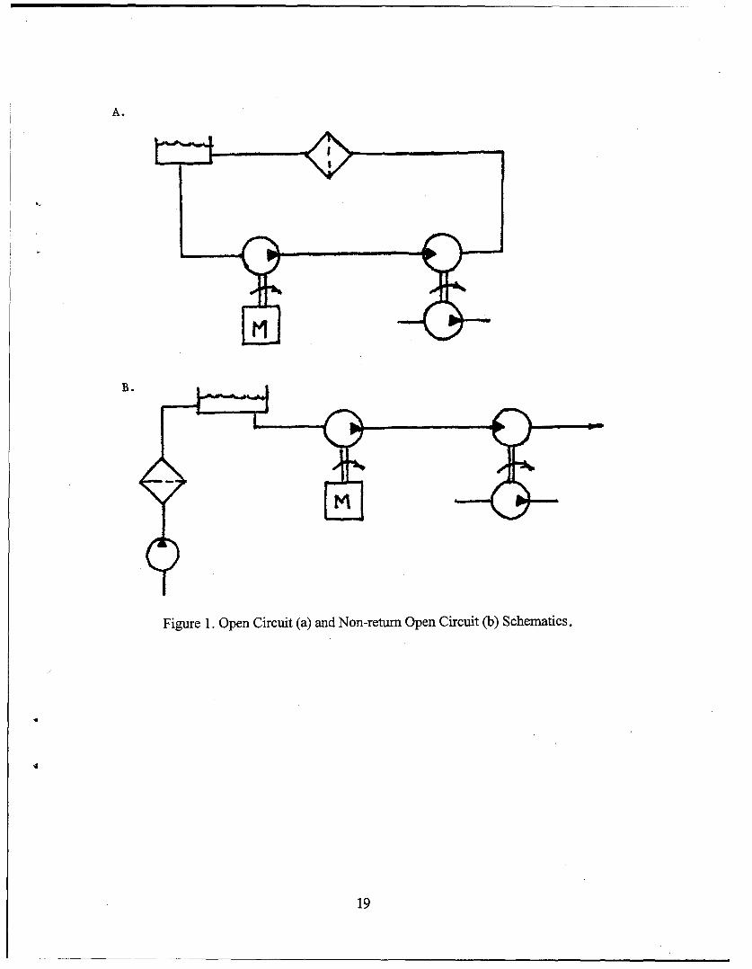
Beyond any environmental reasons for adopting seawater hydraulics, a great advantagefor using seawater hydraulics is the use of an open circuit design without a fluid return hosebetween the hydraulic pump and motor. For purposes of this report, the reader should understandthat this non-return open circuit design is unique to seawater and water hydraulic systems.Unlike conventional open circuit designs were the fluid is returned to the power source reservoir,

the non-return open circuit design permits discharge of spent fluid at the work site. Figure 1shows the conventional open circuit schematic in comparison with the non-return open circuitschematic.
A single transmission hose for the non-return open circuit is a great benefit to theoperator in terms of weight and handling. It allows a longer distance between the prime moverand the work site because return line back pressure losses are eliminated. Because the fluid isnot repeatedly cycled, there is little concern for heat build up, eliminating the necessity for J,
hydraulic fluid cooling. The non-return open circuit system without these components can yieldthe greatest weight savings over conventional circuit design.
When comparing individual hydraulic components for seawater and oil systems, there isno inherent weight savings associated with the seawater hydraulic component. In fact,commercialization of oil hydraulic components generally provides a greater selection of lighterweight hydraulic components.
Seawater hydraulic technology for high pressure hydraulic systems is relatively newtechnology. Table 1 presents a summary of available seawater hydraulic components for severalcandidate systems. The table also highlights areas where some effort in technology developmentis necessary to achieve the capability. While not inclusive of all manufactures, the table isintended to show basic capabilities and areas of deficiency.
In addition to the NFESC effort to reduce transfer pump system weight throughapplication of seawater hydraulic system design, the Carderock Detachment of the Naval SurfaceWeapons Center (CDNSWC) at Annapolis, Maryland is conducting a separate investigation intothe use of composites for select transfer pump components as a means to reduce pump weight(Ref 2). The weight savings associated with the seawater hydraulic system design is intended tocompliment the accomplishments of CDNSWC. Application of composite technology to specificseawater hydraulic components may be appropriate to augment any systems weight savings.
Component Description
The submersible CCN- 150 transfer pump shown in Figure 2 is part of the Navy and CoastGuard petroleum, oils and lubricants transfer (POL) system (Ref 3). The CCN-150 is a singlestage centrifugal pump designed for high pumping efficiency and prolonged immersion inseawater and petroleum products. The pump used by the Coast Guard is substantially the sameas the pump held in the Emergency Ship Salvage Material (ESSM) equipment pool maintainedby the Navy. For this report, a generic CCN-150 designation will be used unless a specificreference to model number is required. Table 2 summarizes the component weight of the transferpump equipment.
The Navy issue CCN-150-lC Thune Eureka and the CCN-150-3C Kvaerner Eureka arelimited to 2,370 psig and 52 gpm of hydraulic supply as measured at the pump hydraulic inlet, or2,500 psig and 52 gpm of hydraulic supply as measured by the hydraulic prime mover gauges.Because of shaft seal failure at the motor/impeller interface, these units should not exceed 200psig of back pressure as measured at the pump hydraulic outlet. The pump is reported to weigh279 pounds (Ref 2).
The Coast Guard has a newer CCN-150-5C Kvaemer Eureka pump which most notablydiffers in flow rate from the -IC and -3C models. Data obtained from the USCG providesCCN-150-5C pump curves for flow rates up to 79 gpm. Review of the specifications for the
2

*00
wl r0. C C.
E~~. E .t
.0 .0 t- .0 u -0 'A cc 0
u Co2 o.n.
.00 -11:rM0
E C,
U-
Z 4
E - L0 ~.024) ~ . r4 :~
0 0
61 :Sc E)C.
~E ~ .-
2 > J5 C. ~~
C)
Cu 0.C r-
:=
*-~ ~~ 0 CZ '- 400~~~P o ) )~ .0'D u Oq .E~ E E) .
~C' .0a
Ci)
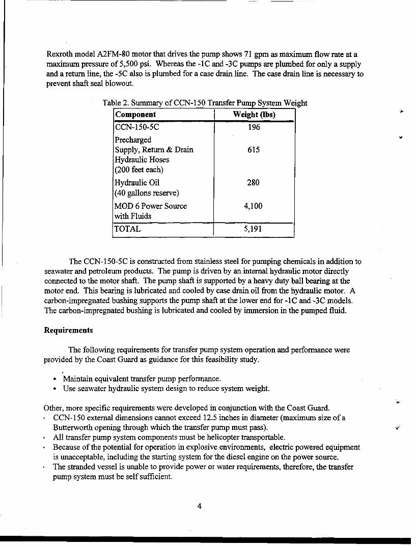
Rexroth model A2FM-80 motor that drives the pump shows 71 gpm as maximum flow rate at amaximum pressure of 5,500 psi. Whereas the -1C and -3C pumps are plumbed for only a supplyand a return line, the -5C also is plumbed for a case drain line. The case drain line is necessary toprevent shaft seal blowout.
Table 2. Summary of CCN-150 Transfer Pump System Weight
Component Weight (ibs) 4.
CCN-150-5C 196
PrechargedSupply, Return & Drain 615Hydraulic Hoses(200 feet each)
Hydraulic Oil 280(40 gallons reserve)
MOD 6 Power Source 4,100with Fluids
TOTAL 5,191
The CCN-150-5C is constructed from stainless steel for pumping chemicals in addition toseawater and petroleum products. The pump is driven by an internal hydraulic motor directlyconnected to the motor shaft. The pump shaft is supported by a heavy duty ball bearing at themotor end. This bearing is lubricated and cooled by case drain oil from the hydraulic motor. Acarbon-impregnated bushing supports the pump shaft at the lower end for -1C and -3C models.The carbon-impregnated bushing is lubricated and cooled by immersion in the pumped fluid.
Requirements
The following requirements for transfer pump system operation and performance wereprovided by the Coast Guard as guidance for this feasibility study.
"* Maintain equivalent transfer pump performance."* Use seawater hydraulic system design to reduce system weight.
Other, more specific requirements were developed in conjunction with the Coast Guard.
CCN-150 external dimensions cannot exceed 12.5 inches in diameter (maximum size of a
Butterworth opening through which the transfer pump must pass).* All transfer pump system components must be helicopter transportable.* Because of the potential for operation in explosive environments, electric powered equipment
is unacceptable, including the starting system for the diesel engine on the power source.The stranded vessel is unable to provide power or water requirements, therefore, the transferpump system must be self sufficient.
4

An in-kind replacement of the Rexroth hydraulic motor is desired. The hydraulic motormust be capable of submerged operation since the motor is in direct contact with the pumpedfluid. The motor should fit within the available space so as not to interfere with the pumped fluidflow. Specific performance requirements for the transfer pump were developed through reviewof the CCN-150 hydraulic motor specification (CCN-150-5C uses a Rexroth A2FM-80 seriesmotor) and of the operation manuals. Figure 3 provides curves for CCN-150 performance forpumping water and for pumping oil.
FINDINGS
The investigation into a seawater hydraulic conversion for the CCN-150 included aliterature survey, concept development studies, and conversations with USCG Pacific StrikeTeam (PST) members to determine system operational data. In addition to demonstrating theoperation of the CCN-150 transfer pump system, the PST also provided a CCN-150-IC pump forfamiliarization and as a platform for future laboratory testing. The following sections describethe results of our study on the CCN-150 transfer pump system. A listing of citations for theliterature survey can be found in Appendix A.
Motor Replacement
One of the first areas investigated was availability of a suitable seawater hydraulic motorto replace the Rexroth motor. Because input torque curves were not available for the CCN-150pump impeller, the Rexroth motor output specifications were used to select candidate motors.Our literature searches and Commerce Business Daily sources sought announcements identifiedtwo potential vendors: Fenner Water Hydraulics and Danfoss Fluid Power. Both manufacture'sspecialize in freshwater hydraulic system components. Copies of the Fenner and Danfossliterature can be found in Appendices B and C, respectively. A listing of the responses to thesources sought announcement is included as Appendix D.
Table 3 presents a comparison of closest available hardware from each vendor against theRexroth motor specification. Though capable of operation up to 5,800 psi input pressure, Table3 specifications on the Rexroth motor were limited to 2,370 psi for this comparison for tworeasons. First, 2,370 psi is the reported (Ref 4) pressure limit for operation of the CCN-150-ICand -3C transfer pumps. The second reason to limit the comparison to 2,370 psi is that theavailable USCG power sources are unable to provide higher pressure at the supply flow rate.
Danfoss does not have a motor of the required size range for this application. TheDanfoss MAH 12.5 unit is the largest motor offered at just over 11 horsepower. NFESCcontacted Danfoss representatives in the U.S. and in the U.K.. Danfoss was willing to undertakea development effort for a large motor but they were not offering their larger size pump forconversion to a motor. There is no obvious reason why the larger Danfoss PAH 80 piston pumpcould not be used as a motor. Danfoss may be unwilling to risk company reputation withoutprior investigation. Because the objective is to select off-the-shelf equipment, the Danfoss motorwas not investigated further.
5
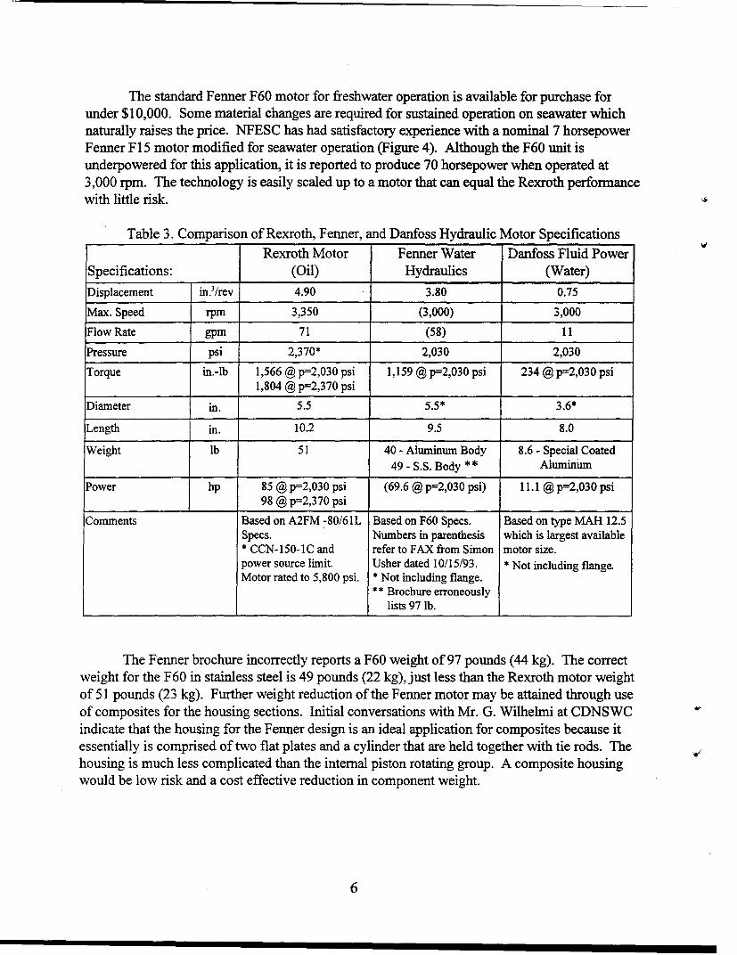
The standard Fenner F60 motor for freshwater operation is available for purchase forunder $10,000. Some material changes are required for sustained operation on seawater whichnaturally raises the price. NFESC has had satisfactory experience with a nominal 7 horsepowerFenner F 15 motor modified for seawater operation (Figure 4). Although the F60 unit isunderpowered for this application, it is reported to produce 70 horsepower when operated at3,000 rpm. The technology is easily scaled up to a motor that can equal the Rexroth performancewith little risk.
Table 3. Comparison of Rexroth, Fenner, and Danfoss Hydraulic Motor SpecificationsRexroth Motor Fenner Water Danfoss Fluid Power
Specifications: (Oil) Hydraulics (Water)
Displacement in.3/rev 4.90 3.80 0.75
Max. Speed rpm 3,350 (3,000) 3,000
Flow Rate gpm 71 (58) 11
Pressure psi 2,370* 2,030 2,030
Torque in.-lb 1,566 @ p=2,0 30 psi 1,159 @ p=2, 030 psi 234 @ p=2 ,030 psi1,804 @ p=2,370 psi
Diameter in. 5.5 5.5* 3.6*
Length in. 10.2 9.5 8.0
Weight lb 51 40 - Aluminum Body 8.6 - Special Coated49 - S.S. Body ** Aluminum
Power hp 85 @ p=2,030 psi (69.6 @ p=2,030 psi) 11.1 @ p=2 ,0 3 0 psi98 @ p=2,370 psi
Comments Based on A2FM -80/61L Based on F60 Specs. Based on type MAH 12.5Specs. Numbers in parenthesis which is largest available* CCN-150-1C and refer to FAX from Simon motor size.power source limit. Usher dated 10/15/93. * Not including flange.Motor rated to 5,800 psi. * Not including flange.
** Brochure erroneouslylists 97 lb.
The Fenner brochure incorrectly reports a F60 weight of 97 pounds (44 kg). The correctweight for the F60 in stainless steel is 49 pounds (22 kg), just less than the Rexroth motor weightof 51 pounds (23 kg). Further weight reduction of the Fenner motor may be attained through useof composites for the housing sections. Initial conversations with Mr. G. Wilhelmi at CDNSWCindicate that the housing for the Fenner design is an ideal application for composites because itessentially is comprised of two flat plates and a cylinder that are held together with tie rods. Thehousing is much less complicated than the internal piston rotating group. A composite housingwould be low risk and a cost effective reduction in component weight.
6

Hydraulic Flow Restrictions.
As with any hydraulic system, a significant reduction in performance results from returnflow fluid frictional losses. This is problematic in the current transfer pump system because theCoast Guard needs the ability to add hose length to the system in order to extend operatingdistance from the power source. As the 50-foot sections of hydraulic hose are added using quickdisconnect hose couplings, system efficiency decreases. The quick disconnects, small hose size,and extended lengths contribute to the total flow restriction.
The CCN- 150-5C transfer pump operations manual specifies a 1-inch-diameter supplyand a 1.5-inch-diameter return hose to pass a maximum 79-gpm flow rate. The Naval SeaSystems Command (NAVSEA) Technical Manual (Ref 4), applicable to the -IC and -3C transferpumps, specifies a 1-inch-diameter hose size for both supply and return hose. These early modelpumps are limited to a 52-gpm flow rate. The PST uses a 1-inch-internal diameter supply andreturn hose size. A 1/2-inch-diameter case drain line is used with the -5C pump.
The following example illustrates the significance of these frictional losses in the CoastGuard system. Table 4 shows a 1.19-psi/foot drop in pressure at a 50-gpm flow rate through a1-inch-diameter hose or a 238-psi drop over a 200-foot hose length. Add to this a 20-psi drop foreach of five quick disconnects used to join the 50-foot hose sections and the total pressure drop isover 300 psi. This is 100 psi in excess of the maximum 200-psi return line back pressurespecified in the NAVSEA technical manual. At 50 gpm, this pressure drop equates to more thanan 8 horsepower loss in system power. This energy waste goes directly into heating the fluid,causing a loss in fluid viscosity. As the hydraulic fluid thins, the volumetric efficiency of theprime mover pump and the CCN-150 internal motor decrease due to internal leakage. The resultis an overall loss in pump system performance.
A larger diameter return line will improve transfer pump performance for the currenthydraulic system and will be required to operate at the full 79-gpm flow rate capacity of theCCN-150-5C. Table 4 shows that a 1.25-inch-diameter hose at 50 gpm results in a 78-psipressure drop over a 200-foot hose length. Even after adding the 100-psi pressure loss associatedwith the five quick disconnects, the larger hose diameter provides a significant improvement. Ata 70-gpm flow rate, the 1.25-inch-diameter hose produces a total of 252-psi drop over a 200-foothose length including quick disconnects. At 70 gpm, the 1.5-inch hose results in a total of162-psi pressure drop for the same hose condition.
An advantage for the seawater hydraulic system is that smaller diameter hoses forequivalent flow rates can be used because of the lower viscosity of seawater. The seawater primemover pump and seawater motor are designed for low viscosity seawater operation. Table 5shows that a seawater flow rate of 50 gpm through a 1-inch-diameter hose results in a 136-psipressure drop over a 200-foot hose length. This is an acceptable drop in pressure and the smallhose size can achieve desired weight savings and flexible handling characteristics.
7

Table 4. Fluid Flow Velocity and Pressure Drop for Hydraulic Oil
Flow Rate Hose Diameter Pressure Drop(gpm) (in.) (psi/ft)
1.00 0.43
30 1.25 0.14
1.50 0.06
1.00 0.76
40 1.25 0.25
1.50 0.10
1.00 1.19
50 1.25 0.39
1.50 0.16
1.00 1.71
60 1.25 0.56
1.50 0.13
1.00 2.33
70 1.25 0.76
1.50 0.31
Table 5. Fluid Pressure Drop for Seawater Versus Hydraulic Oil for a 1-inch-diameter HoseFlow Rate Seawater Hydraulic Oil
(gpm) Pressure Drop Pressure Drop(psi/ft) (psi/ft)
30 0.24 0.43
40 0.43 0.76
50 0.68 1.1960 0.97 1.71
70 1.32 2.33
8

Hose Selection
Table 6 provides a comparison of select thermoplastic hose against the wire-reinforcedhose currently in use by the PST. Thermoplastic hose provides a weight savings of as much as75 percent over wire-reinforced rubber hose. The Aeroquip FC324-16 hose used on the transferpump system is rated to 4,000-psi working pressure and weighs 1.22 pounds per foot. It shouldbe noted that the 4,000-psi working pressure of the FC324-16 hose is 33 percent greater than thepressure capability of the USCG designed Duetz power source. This hose however, appears tobe the best rated in terms of weight per foot. See Appendix E for a complete listing of the hosesincluded in this study.
Aeroquip stocks a thermoplastic 1.25-inch-diameter hose (p/n FC701-20) that is rated to2,500 psi working pressure and weighs 0.58 pounds per foot. The 12-inch bend radius isequivalent to the bend radius for the current FC324-16 hose. Using this hose on the return sidefor the transfer pump would provide dual benefit. There would be a 32 percent reduction inprecharged hose weight over the FC324-16 hose (a 95-pound savings on a 200-foot returnincluding the weight of the oil). Additionally, the hydraulic flow restriction would beminimized.
Parker Hannifm offers a special order 1.5-inch-diameter thermoplastic hose (p/n573X-24) rated to 3,000 psi working pressure. This hose has a 18-inch minimum bend radiusand a weight of 0.81 pounds per foot. This hose would satisfy future requirements for oil flowrates through 79 gpm. A 200-foot precharged length of this hose would still retain a 3 percentreduction in hose weight over the FC324-16 hose (a 10-pound savings for a 200-foot hosesection including the weight of the oil).
Table 6. Comparison of 1 -inch-diameter Thermoplastic Hydraulic Hose Against Currently UsedWire-braided Hose
Hose Description Working Bend Radius Weight PerPressure (in.) Foot (ib)
(psi)
Aeroquip FC324-16 (Wire Braided) 4,000 12 1.22
Parker 593-16 (Thermoplastic) 3,250 8 0.68
Furon Synflex 3350/3360-16 3,000 8 0.42(Thermoplastic)
Parker 573X-16 (Thermoplastic) 3,000 10 0.41
Aeroquip FC702-16 (Thermoplastic) 3,000 12 0.36
Aeroquip FC701-16 (Thermoplastic) 2,500 12 0.36
Parker HPSH- 16 (Thermoplastic) 2,500 4 0.35
For a seawater system, the lower viscosity of seawater allows use of smaller diameterhose when compared to equivalent oil flow rates. Use of 1-inch-diameter thermoplastic hoserated to 3,000 psi working pressure would provide acceptable performance for a seawater
9

hydraulic transfer pump system. Furon Synflex 3350/3360-16 thermoplastic hose can meet thisworking pressure and it weighs 0.42 pounds per foot with a minimum bend radius of 8 inches.
This hose is recommended over the slightly lighter Aeroquip FC702-16 hose because of itsflexibility and the polyurethane jacket. Though possible not as robust as rubber jacketedwire-braided hose, the polyurethane jacketed thermoplastic hose should provide suitableprotection from abrasion caused by deck handling. Use of the Synflex hose with a seawaterhydraulic system will provide a 65 percent reduction in hose weight (a 320-pound savings for200 feet each of supply and return) over the current oil hydraulic system.
Power Source Conversion
Light weight is a primary factor although the power sources are not required to be manportable. Two power sources have been used by the Coast Guard with more or less success tooperate the CCN-150 transfer pump. Table 7 is a comparison of the specifications for the NavyMOD 6 and the Coast Guard power sources. Each unit can supply a typical flow rate of 52 gpmat 2,500 psi. This is well off the maximum 79 gpm at 5,000 psi capability of the CCN-150-5Cbut is at the best performance specification for the CCN-150-1C.
Table 7. Comparison of Navy MOD6 and Coast Guard Hydraulic Power Source SpecificationsPower Source Weight (lb) Dimensions Flow Rate
(in.) Capability
Navy MOD 6 4,100 98 x 34 x 58 52 gpm at 2500 psi
Coast Guard 1,735 68 x 40 x 48 50 gpm at 3000 psiDuetz
The NAVSEA MOD 6 power source, part of the Coast Guard Viscous Oil Pump System(VOPS), is used by the PST for CCN-l 50-5C operation. This skid-mounted power source ispowered by a two stroke diesel with a twin vane pump. Each pump section is capable of anindependent 26-gpm flow rate. Operation of the CCN-150 requires combining the two outputs tosupply 52 gpm at 2,500 psi. The addition of a case drain return fitting to the reservoir wasrequired to accommodate the CCN-150-5C. Because of weight, the MOD 6 power source is notconsidered a good candidate to base a seawater conversion. Figure 5 is a photo of a MOD 6power source used by the PST.
PST members report the MOD 6 power source is more capable of maintainingperformance for extended duration because of the two stroke diesel design. Our investigationsuggests that the sustained performance is the result of lower frictional losses. The output of thetwin vane pump is supplied to the CCN-150 via dual 1-inch-diameter supply and return hoses.The flow is combined at the pump using a custom manifold (Figure 6). The dual hose has theeffect of reducing flow restrictions and would be equivalent to using a single 1.4-inch-diameterhose. Obviously, the benefit is a significantly reduced pressure drop afforded by the larger flowarea leading to less heating and viscosity loss in the hydraulic fluid.
The USCG lightweight power source is powered by a Duetz four stroke diesel engine.This skid-mounted power source includes a variable displacement piston pump that provides 50
10

gpm at 3,000 psi maximum pressure. Reports by PST members that this power source is unableto maintain extended performance are attributed to the flow restriction and viscosity lossdiscussed earlier in this report. Conversion of this power source or development of a powersource around the Duetz engine is a viable alternative for future seawater operation.
Because of the potential for operation in an explosive atmosphere, the Coast Guard uses ahydraulic starter to start the diesel engines on the MOD 6 and Duetz power sources. Ether isused in cold climates to assist in diesel start because of the absence of glow plugs. The hydraulicstarter consists of a hand pump that draws fluid from the hydraulic system oil reservoir topressurize an accumulator. Release of the accumulator charge drives a small hydraulic motor torotate the engine for starting. Figure 7 shows the hydraulic starter motor and associatedaccumulator on the Duetz power source.
Conversion of this starting system to a seawater hydraulic system appears to be within theavailable technology. Selection of one of the smaller Fenner motors may be adequate for such aconversion, however, a specific starter design was not addressed in this study. Maintaining theexisting oil hydraulic starter system is recommended at this point in the project. This wouldrequire a small (approximately 1 gallon) oil resevoir to operate the starter.
Selection of a Prime Mover Pump
Ancillary equipment such as filters, hoses, and valves are available from manycommercial sources, however, the selection of a prime mover seawater pump, like the seawatermotor, is limited to a few manufacturers. Table 8 presents the products of several pumpmanufacturers identified in the literature search.
Table 8. Summary of Candidate Prime Mover PumpsManufacturer/Model Type Capacity Weight (lb)
Aqua-Dyne/GA Series Triplex Plunger 60 gpm @ 550 rpm 1,4002,400 psi @ 100 hp
Giant/Series XP 15,000 Triplex Plunger 55 gpm @435 rpm 7502,600 psi @ 100 hp
Hydrowatt/R130S Radial Piston 52 gpm @ 1500 rpm 5074600 psi @136 hp
Hauhinco/RKP-160 Radial Piston 62 gpm @ 1500 rpm 4852,900 psi @ 100 hp
"Fenner/F120 Axial Piston 48 gpm @ 1500 rpm 992,030 psi @ 60 hp
Danfoss/PAH 80 Axial Piston 29 gpm @ 1500 rpm 812,320 psi @ 44 hp
FMC */Series C52.0 Axial Piston 52 gpm @ 1750 rpm 651,000 psi @ 32 hp
* Previously manufactured under the trade name Delpump by CHPT Incorporated.
11

The Giant, Aqua-Dyne, and Hydrowatt pump designs are old technology in that they relyon oil lubrication at critical wear interfaces. These triplex plunger and radial piston designs paya significant weight penalty for the use of an intermediate oil lubricated pump section whichmust be sealed from the water section of the pump. The size and weight make these pumpsunacceptable for USCG application.
The three axial piston type pumps shown in Table 8 represent new technology for highpressure pumping of water in that they are totally water lubricated. Each of these units isdesigned for water as the hydraulic fluid and lubricant. The Danfoss PAH 80 is the smallest unitand would not be able to meet the flow requirements to operate the transfer pump. Combiningthe flow output from twin PAH 80 units, similar to the MOD 6 power source twin vane pumparrangement, is one approach to meeting the flow requirements. This arrangement would alsoprovide some backup capacity in the event of a single pump failure. Likely a gearboxarrangement would be required to split the diesel output to each pump. The addition of agearbox however, would be additional weight.
The FMC Series C52.0 is a lightweight composite pump previously marketed as Delpumpby CHPT. At 65 pounds, the C52.0 has the lowest weight of the available pumps. The singulardrawback of this pump is the low output pressure of 1,000 psi. The principal market for thisdesign is reverse osmosis units and not the demands of a hydraulic system. NFESC experiencewith this design has shown that the upper limit for pressure output is around 1,500 psi. Becauseof this limitation, the FMC pump would not meet USCG requirements.
The Fenner F120 pump best fills the need for a prime mover pump even though it isunderrated. The flow rate for this pump may be increased to the 60 gpm needed to operate theF60 size motor by operating at a faster shaft speed. The F120 pump provides a compact designcapable of high pressure operation to 2,030 psi. The literature reported weight of the F120 pumpis out of date. Fenner now reports a weight of 99 pounds for the F120 pump. Like the motor, theuse of composites for the housing could lead to an important reduction in unit weight.
Other Hydraulic Equipment
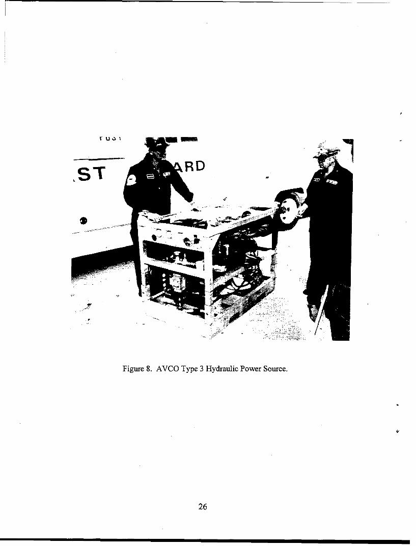
The Strike Teams have a host of portable hydraulic equipment, most of which use the twopreviously reported hydraulic power sources. A third power source on inventory at the PST isreferred to as the AVCO Type 3 (Figure 7). This 70 horsepower power source is primarily usedfor the Open Water Oil Containment Recovery System and requires a separate oil cooler unit todissipate waste hydraulic oil heat. Other equipment supported by this power source can becharacterized as having a small hydraulic demand in comparison to the CCN- 150 pump. Thevarious oil recovery type equipment listed below requires from 3 to 25 gpm at 2,500 psi:
* Vessel of Opportunity Skimmer System (VOSS)* Viscous Oil Pump System (VOPS)* Retrieval Rack* Inflatable Boom Blower* Pump Float Skimmer* Archimedes Screw
12
The nature of operation from small boats or barges makes this equipment ideal foroperation on seawater hydraulics. Many of the advantages for an open circuit hydraulic systemcan be realized for these systems. Specific investigation of seawater hydraulic conversions ofthis equipment, however, was beyond the scope of this work.
SYSTEM CONCEPTS
Two circuit design configurations were reviewed for a seawater hydraulic poweredtransfer pump system. A non-return, open circuit system, like that used in the Navy diver toolsystem, potentially offers the best reduction in systems weight. The basic disadvantage of thenon-return open circuit design is that it must be located next to an adequate water supply. Aconventional open circuit system design, like the current oil system design, has the advantage ofoperating from any suitable location without the need for a continuous water supply. Thedisadvantage of the conventional open circuit system design is that it offers limited opportunityfor any weight savings because components such as coolers and return hoses are all required. Acomparison of the two system concepts resulted in the selection of a conventional open circuitsystem design as best meeting USCG operating requirements and project objectives.
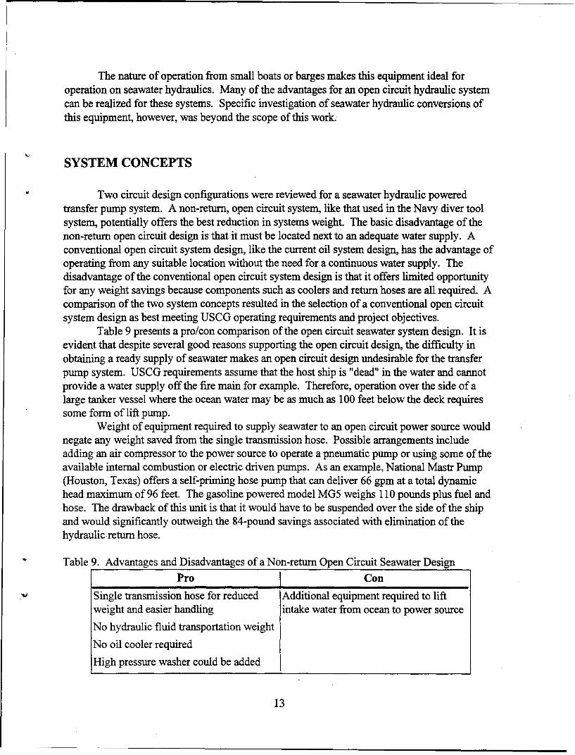
Table 9 presents a pro/con comparison of the open circuit seawater system design. It isevident that despite several good reasons supporting the open circuit design, the difficulty inobtaining a ready supply of seawater makes an open circuit design undesirable for the transferpump system. USCG requirements assume that the host ship is "dead" in the water and cannotprovide a water supply off the fire main for example. Therefore, operation over the side of alarge tanker vessel where the ocean water may be as much as 100 feet below the deck requiressome form of lift pump.
Weight of equipment required to supply seawater to an open circuit power source wouldnegate any weight saved from the single transmission hose. Possible arrangements includeadding an air compressor to the power source to operate a pneumatic pump or using some of theavailable internal combustion or electric driven pumps. As an example, National Mastr Pump(Houston, Texas) offers a self-priming hose pump that can deliver 66 gpm at a total dynamichead maximum of 96 feet. The gasoline powered model MG5 weighs 110 pounds plus fuel andhose. The drawback of this unit is that it would have to be suspended over the side of the shipand would significantly outweigh the 84-pound savings associated with elimination of thehydraulic return hose.
Table 9. Advantages and Disadvantages of a Non-return Open Circuit Seawater Design
Pro Con
Single transmission hose for reduced Additional equipment required to liftweight and easier handling intake water from ocean to power source
No hydraulic fluid transportation weight
No oil cooler required
High pressure washer could be added
13

Alternatively, an open circuit conversion option on a closed circuit system design mayprovide system flexibility for those cases where an adequate supply of water can be provided bythe host ship. The decision on whether to mobilize as a closed or open circuit system could bemade based on the incident report prior to departing on the mission.
A conventional open circuit for a seawater hydraulic system offers greater flexibility forsite selection and does not add lift pump hardware to the equipment list. Table 10 presents thecomponent weight of a conventional open circuit seawater hydraulic transfer pump system andthe expected weight savings.
Table 10. Summary of Seawater Hydraulic CCN-150 Transfer Pump System Weight Savings
Component Weight (lb) Savings (ib)
CCN-150 196 No Change
ThermoplasticSupply, Return & Drain 195 420Hydraulic Hoses(200 feet)
Hydraulic Fluid * 0 280
Seawater Power Source 1,800 2,300 **
TOTAL 2,191 3,000* Assumes capability for one time fill is available on site.
•* Based on MOD 6 power source.
Overall transportation weights are reduced by elimination of hydraulic oil, provided thereis a method on site for a one time fill (about 60 gallons) of the hydraulic system (plus anyrequired make up water). The fire mains or other ship pumps might serve to fill the transferpump system. If water is not available on site, carrying it along adds another 500 pounds tosystem transportation weight.
The weight savings primarily comes from use of thermoplastic hose and a lighter powersource. Parts of both of these weight savings are applicable to present oil hydraulic systems. Thebenefit of thermoplastic hose has been discussed previously. The USCG is already preparing totake advantage of the lighter weight Duetz power source as a replacement for the MOD 6 powersource.
Issues
Unique to seawater hydraulic component design and system operation are the issues ofbearing design and extreme temperature. Probably the most frequently raised issue is theoperating range of seawater. Care must be exercised to maintain the water above freezing orinternal damage to the hydraulic components can result. The second issue is associated withdevelopment of water lubricated technology to support component designs requiring ballbearings. Because seawater does not provide a good lubricating film, all water lubricatedcomponent shaft bearings must now be supported by polymer sleeves rather than conventional
14

ball or roller bearing design. Careful design and operation can minimize the effect of theseissues on the seawater hydraulic system performance.
Temperature. The freezing temperature of seawater falls within the desired transferpump operating envelope of 0°F to 140°F. A frozen seawater hydraulic system must be thawedprior to use. Once a seawater system is operating, waste heat keeps the seawater from refreezing.This is particularly true for a conventional open loop circuit where recycling keeps the fluidtemperature above freezing. If the situation warrants, an environmentally friendly glycoladditive could be used in the system to lower the freezing point.
In comparison to oil, water has a narrow viscosity range making it an ideal fluid for ahydraulic system. While the kinematic viscosity of a general purpose hydraulic oil(MIL-H-5606) may undergo a 35 to 40 centistokes decrease over a 100°F increase intemperature, water undergoes less than a 2 centistokes change. Because water does not thin outlike hydraulic oil as it gets hotter, water hydraulic components tend not to suffer from increasedinternal leakage leading to reduced volumetric efficiency.
Manufacturers of oil hydraulic equipment recommend a fluid operating temperature rangeof 40°F to 140'F. Below 40'F, the oil must be heated and gradually circulated to prevent systemdamage. Hydraulic fluid additives help ensure (within this temperature envelope) that the oilviscosity will not be too thick for cold weather startup or too thin for warm weather operation.As temperature increases, these additives break down and the hydraulic fluid looses its desiredproperties.
Between the extremes of freezing and boiling, seawater provides a much largertemperature range from about 40'F to 180°F. Within this range, viscosity is relatively constantand there is no need for additives. A conventional open circuit seawater hydraulic system willrequire a hydraulic fluid radiator to transfer the excess heat to the atmosphere. Construction ofthe heat exchanger will require corrosion immune material because of the corrosive nature ofseawater.
Pump Bearing Design. The CCN-150 pump shaft is supported by a heavy duty ballbearing at the motor end (Figure 9). This ball bearing is lubricated and cooled by case drain oilfrom the hydraulic motor. Because of the large axial and lateral loads carried by this bearing, theuse of a polymer bushing for water lubrication may not be feasible. Such a bushing designwould require a larger shaft diameter and additional bearing length in order to establishhydrodynamic support. As a result, the transfer pump may be larger and heavier.
A carbon impregnated bushing supports the pump shaft at the lower end for -IC and -3Cmodels. The carbon impregnated bushing is lubricated and cooled by the fluid being pumped.Damage to this bearing (Figure 10) suggests that either the unit was run dry or was otherwisedamaged during operation or maintenance. This damage is a good reminder of how delicatebushings can be. In the CCN-150-5C, this bushing has been removed and the impeller load issupported completely by the bearing at the motor end.
In this case, the bearing at the motor end should be sealed from the pumped fluid andseawater hydraulic system, and lubricated with oil. Maintaining this sealed oil chamber forbearing lubrication would be a minor addition to the maintenance procedure. Pressurecompensation of this oil cavity would not be necessary due to the limited depths that the transferpump is submerged.
15

CONCLUSIONS
The following conclusions have been drawn as a result of this investigation into theapplication of seawater hydraulics for the purpose of reducing the CCN- 150 transfer pumpsystem weight:
1. Conversion of the CCN-150 transfer pump for seawater hydraulic system operation isfeasible using commercially available technology. Replacement of the existing oil hydraulicmotor with an appropriately sized seawater compatible motor will provide existing transfer pumpperformance with no weight penalty.
2. A non-return open circuit hydraulic system design is not the best choice for theCCN-150 transfer pump system because USCG requirements assume that the stricken tank vesselis "dead" in the water and unable to supply the seawater demand. Addition of a separate liftpump to supply the transfer pump system with seawater negates any weight savings associatedwith the open circuit design.
3. Given the desired operation scenario, a conventional open circuit hydraulic systemdesign provides greater flexibility for on-site location and easier equipment support. As much as3,000 pounds can be saved from the present CCN-150 transfer pump system weight byconverting to seawater hydraulics and by using thermoplastic hose.
4. Freezing temperatures can cause equipment damage and system failures if the seawaterhydraulic system is not adequately warmed prior to operation. A open circuit hydraulic systemdesign can minimize the effect of operation in a cold climate because the seawater shouldnaturally warm as it is recirculated. In addition, the use of an antifreeze additive is an option in aclosed circuit system.
5. A power source option to convert from a conventional to a non-return open circuitconfiguration may provide additional system flexibility for situations where a continuous supplyof water can be provided by the host ship. The non-return open circuit design could then provideadditional weight savings through removal of the hydraulic return hose.
6. The elimination of hydraulic oil will benefit the USCG by reducing system weight andthe environmental hazards associated with oil hydraulic system operation. Much of this benefitwill be realized during month-to-month equipment maintenance and ready load preparation at thehome port.
7. A 370-pound weight savings can be achieved with the present oil hydraulic transferpump system if thermoplastic hose is used instead of the wire braided reinforced rubber hose(based on 1-inch-diameter supply/return and 0.5-inch-diameter case drain hose sizes).
16

8. Review of the CCN-150 operating parameters showed that the present 1-inch-diameterhydraulic return hose is too restrictive for a 52-gpm oil flow rate. A significant improvement inthe CCN-150 and Duetz power source performances would be achieved by using a1.25-inch-diameter hose. Any weight penalty associated with the larger diameter hose can bereduced by using thermoplastic hose.
9. The NSF has hydraulic powered oil recovery and cleanup equipment that is smaller inhorsepower than the CCN-150 transfer pump system. The use of this equipment from smallvessels or on land makes these systems better candidates for seawater hydraulic operation. Theapplication of the open circuit seawater hydraulic system design may be advantageous for thisequipment.
RECOMMENDATIONS
The following recommendations are presented based on the results and conclusions ofthis Phase I investigation into seawater hydraulic operation of the CCN-150 transfer pumpsystem:
1. Demonstration of the conversion of the CCN-150 pump by replacement of thehydraulic motor is recommended as a means to identify how well the Fenner seawater motormatches the pump input torque and speed requirements. Lessons learned from thisdemonstration would serve as a design guide for full scale motor specifications for the seawaterhydraulic CCN- 150 transfer pump.
2. Consultation with the composites group at CDNSWC Annapolis, Maryland to assistNFESC in the development of a lighter weight Fenner motor and pump is recommended. Usingthe design information provided by the demonstration and CDNSWC's expertise in theapplication of composites technology, NFESC may be able to achieve additional weight savingsfor the CCN- 150 transfer pump.
3. The current CCN-150 transfer pump system should be modified to reduce weight andincrease pump and power source performance. NFESC recommends replacing the existingwire-braided reinforced hoses with equivalent rated thermoplastic hose of 1-inch-diametersupply, 1.25-inch-diameter return, and 0.5-inch-diameter case drain. A gradual replacementprogram would minimize the cost of this conversion. All teams would need to change in order tomaintain equipment interchangeability.
4. Investigation into the application of non-return, open circuit seawater hydraulic systemdesign for the smaller USCG operated equipment is recommended. A feasibility study, similar inscope to this study, is recommended as a first means to identify the nature of this equipment andthe advantages for seawater hydraulic operation.
17
REFERENCES
1. J. Kunsemiller and S. Black. "Case Study of an Environmentally Safe Diver Tool System,"Presented at the Underwater Intervention Conference, San Diego, CA, Feb 1994.
2. H.K. Telegadas. CARDEROCKDIV-SSM-64-94/07: Feasibility of using composite materialsto reduce the weight of the CCN-150 transfer pump, Mar 1994.
3. Naval Sea Systems Command. NAVSEA S0300-A6-MAN-050: U.S. Navy ship salvagemanual, Volume #5 ( POL Offloading), 31 Jan 1991.
4. Naval Sea Systems Command. NAVSEA S6225-DX-MMO-010: Technical manual,Submersible pump subsystem CCN-150, 15 Aug 1980.
5. Naval Sea Systems Command. NAVSEA S0300-BR-MAN-010: Pollution response guide andequipment manual.
j1
18
A.
B.
Figure 1. Open Circuit (a) and Non-return Open Circuit (b) Schematics.
19

Figure 2. CCN-150 transfer pump.
20
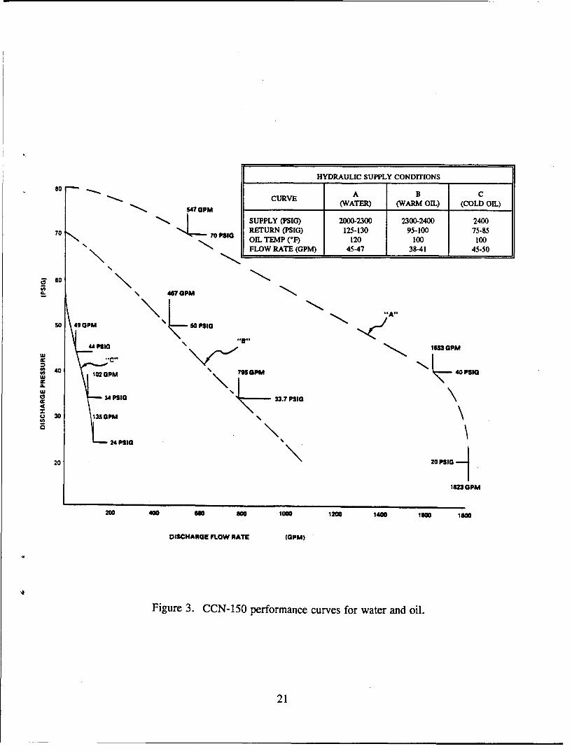
80 HYDRAULIC SUPPLY CONDITIONS
CURVE A B C
17 GPM _(WATER) (WARM OIL) (COLD OIL)
'o PS' SUPPLY (P1)2000-2300 2300-2400 2400
70 RETURN (PSIG) 125-130 95-100 75-85OIL TEMP ('F) 120 100 100"FLOW RATE (GPM) 45-47 38-41 45-50
60S04Pa GPM
so 49 GPM So "A"
" P111
102 PM 79OPM 40PSlO
UJ
34 PSG 33.7 PSIG
30 1250GPM
0 24 PSIG
0
182= GPM
200 4010 a 00 1000 1200 1400 1600 1600
DISCHARGE FLOW RATE (GPM)
Figure 3. CCN-150 performance curves for water and oil.
21

SNAVAL CIVIL ENGINE[ERING LABORATORY, PORT WM£EME, CA 93043
Figure 4. Fenner 7 hp seawater motor.
22

Figure 5. MOD 6 Hydraulic Power Source.
42
23

:1
Figure 6. Manifold for CCN-150-5C to combine MOD 6 power source flow from dual hoses.
24

Figure 7. Hydraulic starter motor and associated accumulator on the Duetz power source.
25
TUU-31so
LST -RD
Figure 8. AVCO Type 3 Hydraulic Power Source.
26

Figure 9. The CCN-150 pump shaft is supported by a heavy duty ball bearing at the motor end.
27
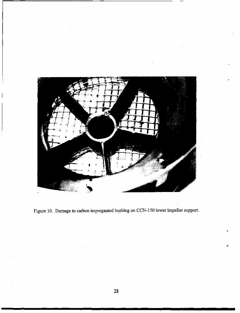
Figure 10. Damage to carbon impregnated bushing on CCN-150 lower impeller support.
28

Appendix A: Literature Survey Citations
A-1

(BLANK)
A-2
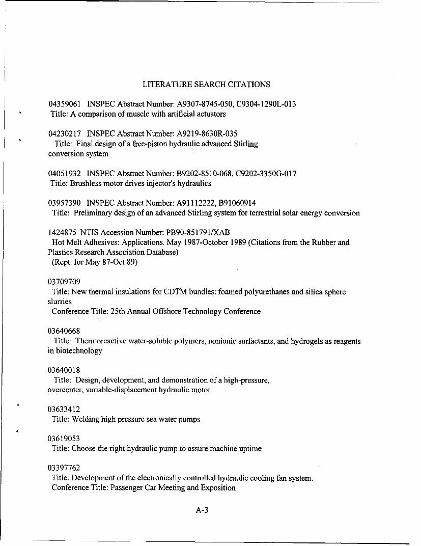
LITERATURE SEARCH CITATIONS
04359061 INSPEC Abstract Number: A9307-8745-050, C9304-1290L-013Title: A comparison of muscle with artificial actuators
04230217 INSPEC Abstract Number: A9219-8630R-035Title: Final design of a free-piston hydraulic advanced Stirling
conversion system
04051932 INSPEC Abstract Number: B9202-8510-068, C9202-3350G-017Title: Brushless motor drives injector's hydraulics
03957390 INSPEC Abstract Number: A91112222, B91060914Title: Preliminary design of an advanced Stirling system for terrestrial solar energy conversion
1424875 NTIS Accession Number: PB90-851791/XABHot Melt Adhesives: Applications. May 1987-October 1989 (Citations from the Rubber and
Plastics Research Association Database)(Rept. for May 87-Oct 89)
03709709Title: New thermal insulations for CDTM bundles: foamed polyurethanes and silica sphere
slurriesConference Title: 25th Annual Offshore Technology Conference
03640668Title: Thermoreactive water-soluble polymers, nonionic surfactants, and hydrogels as reagents
in biotechnology
03640018Title: Design, development, and demonstration of a high-pressure,
overcenter, variable-displacement hydraulic motor
03633412Title: Welding high pressure sea water pumps
03619053Title: Choose the right hydraulic pump to assure machine uptime
03397762Title: Development of the electronically controlled hydraulic cooling fan system.Conference Title: Passenger Car Meeting and Exposition
A-3

03097047Title: New series of petroleum production pump installations.
03042937Title: Efficiency and pressure recovery in hydraulic jet pumping of two-phase gas/liquid
mixtures.
02984700Title: High pressure water-abrasive jet cutting for steel pipes of gas well casings.
Conference Title: Proceedings of the 5th American Water Jet Conference
02984670Title: High pressure hydromilling of concrete surfaces.Conference Title: Proceedings of the 5th American Water Jet Conference
02864465Title: 25 kW(E) free-piston Stirling hydraulic engine for terrestrial solar thermal applications.
Conference Title: Proceedings of the 23rd Intersociety Energy Conversion EngineeringConference
0323974 94R-02830Subfile: RBiodegradable fluids; flow and filtrability tests
0317069 93R-04010Subfile: RWater hydraulic pumps for a safer and cleaner future
0304248 92S-01050Subfile: SH&H Pump introduces new sand dredging technology
0301255 91T-01525Subfile: TLubrication characteristics of oil-hydraulic piston pump motor. Part 2: measurement of oil film
thickness between piston and cylinder
0301111 91S-05694Subfile: STesting of composite pipes in high velocity seawater
0267015 91T-01393Subfile: TLubrication of Oil-hydraulic piston pump/motor. Part 1: Measurement of piston friction force
A-4
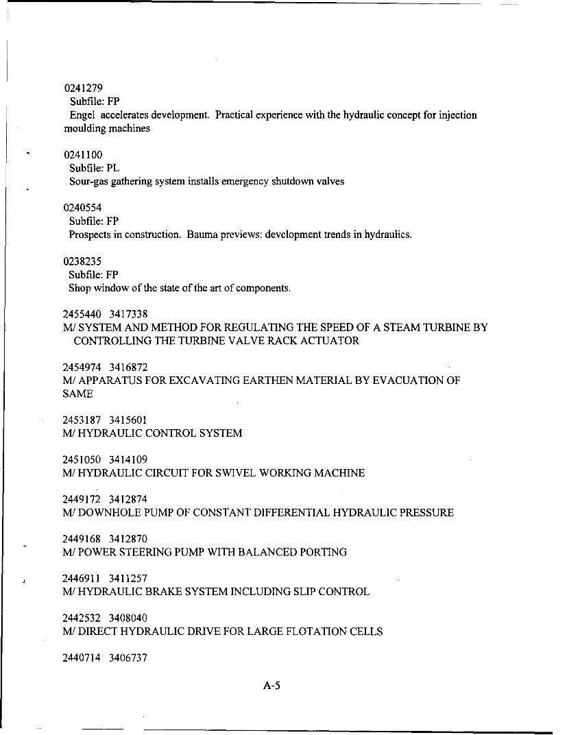
0241279Subfile: FPEngel accelerates development. Practical experience with the hydraulic concept for injection
moulding machines
0241100Subfile: PLSour-gas gathering system installs emergency shutdown valves
0240554Subfile: FPProspects in construction. Bauma previews: development trends in hydraulics.
0238235Subfile: FPShop window of the state of the art of components.
2455440 3417338M/ SYSTEM AND METHOD FOR REGULATING THE SPEED OF A STEAM TURBINE BY
CONTROLLING THE TURBINE VALVE RACK ACTUATOR
2454974 3416872M/ APPARATUS FOR EXCAVATING EARTHEN MATERIAL BY EVACUATION OFSAME
2453187 3415601M/ HYDRAULIC CONTROL SYSTEM
2451050 3414109M/ HYDRAULIC CIRCUIT FOR SWIVEL WORKING MACHINE
2449172 3412874M/ DOWNHOLE PUMP OF CONSTANT DIFFERENTIAL HYDRAULIC PRESSURE
2449168 3412870M/ POWER STEERING PUMP WITH BALANCED PORTING
2446911 3411257M/ HYDRAULIC BRAKE SYSTEM INCLUDING SLIP CONTROL
2442532 3408040M/ DIRECT HYDRAULIC DRIVE FOR LARGE FLOTATION CELLS
2440714 3406737
A-5

M/ COMBINED ANTISKID AND TRACTION CONTROL ELECTRONIC BRAKE SYSTEM2440401 3406424M/ HYDRAULIC CIRCUIT FOR RUNNING A CRAWLER VEHICLE
2434313 3402015M/ HYDRAULICALLY ACTUATED AIRCRAFT ENGINE CONTROL SYSTEM
2425918 3374598M/ SLURRY HAULING VEHICLE
2423909 3373113M/ POWER STEERING PUMP WITH BALANCED PORTING
2414787 3366624M/ METHOD AND APPARATUS FOR HEATING AN ASPHALT PAVING SCREED
2407898 3361609M/ VARIABLE MOMENT VIBRATOR USABLE FOR DRIVING OBJECTS INTO THEGROUND
2396949 3353853M/ HYDRAULIC CIRCUIT WITH COMPENSATOR VALVE BIASED WITH HIGHESTPRESSURE ACTING ON ACTUATORS
2393039 3351268M/ REGENERATIVE THERMAL OXIDATION APPARATUS AND METHOD
2392713 3350942M/ VOLTAGE CONTROLLED HYDRAULIC SETTING TOOL
2390235 3349125M/ COMBINED MARINE REFRIGERATING AND AIR CONDITIONING SYSTEM USINGTHERMAL STORAGE
2379521 3341570M/ PLURAL HYDRAULIC PUMP SYSTEM WITH UNLOADING VALVE
2379471 3341520M/ SYSTEM FOR AUTOMATICALLY OPENING AND CLOSING DOORS OF VEHICLES
2377293 3339989M/ COMPRESSOR ARRANGEMENT SUITABLE FOR TRANSPORT REFRIGERATIONSYSTEMS
2373398 3337396
A-6

M/ VARIABLE SPEED HYDRAULIC PUMP SYSTEM FOR LIQUID TRAILER2358380 3326716M/ ELECTRO-HYDRAULIC VEHICULAR POWER STEERING SYSTEM WITH CLOSEDCENTER VALVING
2350081 3320860M/ MULTIFUNCTION INTEGRATED POWER UNIT AND POWER TRANSFERAPPARATUS THEREFOR
2349921 3320700M/ HYDRAULIC ENERGY SUPPLY CART
2345742 3317747M/ ON-OFF PRESSURE CUTOFF CONTROL FOR A VARIABLE DISPLACEMENTHYDRAULIC PUMP
2345161 3317166M/ HYDRAULIC-MOTOR DRIVE CIRCUIT SYSTEM WITH ANTI-CAVITATIONCONTROL
2337762 9304762C/ MOTION CONTROLLER FOR WASTEWATER TREATMENT TRICKLING FILTER
2337563 3311870M/ VARIABLE CAPACITY PUMP CONTROLLER OF HYDRAULICALLY DRIVENWHEEL
2332756 3308255M/ INTEGRATED PRESSURE AMPLIFICATION AND MODULATION SYSTEM FOR AHYDRAULIC CIRCUIT
2331043 3307019M/ CONTROL AND REGULATING DEVICE FOR A HYDROSTATIC TRANSMISSION
2330934 3306910M/ AUTOMATIC SWIMMING POOL COVER WITH A DUAL HYDRAULIC DRIVESYSTEM
2329793 3306246M/ COMBINED CENTRIFUGAL AND UNDERVANE-TYPE ROTARY HYDRAULICMACHINE
2324100 3302113M/ HYDROSTATIC BRAKING POWER CONVERTER
A-7
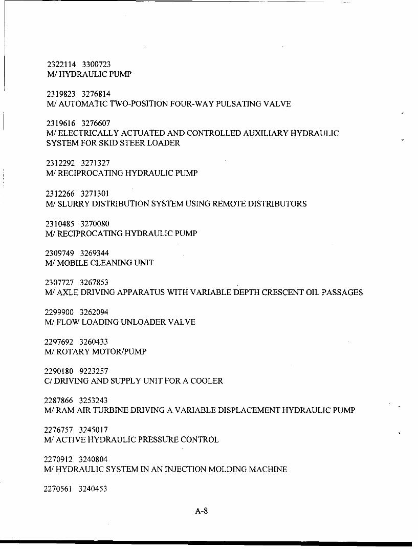
2322114 3300723M/ HYDRAULIC PUMP
2319823 3276814M/ AUTOMATIC TWO-POSITION FOUR-WAY PULSATING VALVE
2319616 3276607M/ ELECTRICALLY ACTUATED AND CONTROLLED AUXILIARY HYDRAULICSYSTEM FOR SKID STEER LOADER
2312292 3271327M/ RECIPROCATING HYDRAULIC PUMP
2312266 3271301M/ SLURRY DISTRIBUTION SYSTEM USING REMOTE DISTRIBUTORS
2310485 3270080M/ RECIPROCATING HYDRAULIC PUMP
2309749 3269344M/ MOBILE CLEANING UNIT
2307727 3267853M/ AXLE DRIVING APPARATUS WITH VARIABLE DEPTH CRESCENT OIL PASSAGES
2299900 3262094M/ FLOW LOADING UNLOADER VALVE
2297692 3260433M/ ROTARY MOTOR/PUMP
2290180 9223257C/ DRIVING AND SUPPLY UNIT FOR A COOLER
2287866 3253243M/ RAM AIR TURBINE DRIVING A VARIABLE DISPLACEMENT HYDRAULIC PUMP
2276757 3245017M/ ACTIVE HYDRAULIC PRESSURE CONTROL
2270912 3240804M/ HYDRAULIC SYSTEM IN AN INJECTION MOLDING MACHINE
2270561 3240453
A-8

M/ MULTI-LANCE TUBE CLEANING SYSTEM HAVING FLEXIBLE PORTIONS2261843 3233947M/ DEVICE FOR PRESSURE-REGULATED VARIABLE DISPLACEMENT MOTORSWITH RPM-DEPENDENT SET PRESSURE COMPENSATION
2261780 3233884M/ PLATING APPARATUS FOR CONSTRUCTING OR REPAIRING A PALLET
2256034 9213424C/ CLEANING METHOD; PRESSURIZATION OF LIQUID WITH GAS DRIVENHYDRAULIC PUMP
2246503 3223180M/ METHOD OF AND APPARATUS FOR HYDRAULICALLY DEFORMING APIPE-SHAPED HOLLOW MEMBER
2246487 3223164M/ HYDRAULIC DOOR ACTUATOR; OPENING AND CLOSING
2244580 3221943M/ HYDRAULIC CLUTCH AND TRANSMISSION ACTUATING SYSTEM
2244543 9209737 3221906CM/ WELL CEMENTING METHOD USING A DISPERSANT AND FLUID LOSSINTENSIFIER; INJECTING ETHOXYLATE AND SULFONATED DISPERSANT BLENDAND ALCOHOL
2244280 3221643M/ HYDRAULIC UNIT FOR DRIVING A TOOL
2240570 3219222M/ INTEGRAL PRESSURE PULSE ATTENUATOR
2233391 3213982M/ HYDROSTATIC TRANSMISSION
2231613 3212719M/ HYDROSTATIC TRANSMISSION WITH INTERCONNECTED SWASH PLATENEUTRAL VALVE AND BRAKE UNIT
2225718 3208751M/ HYDRAULIC APPARATUS INCLUDING A HYDRAULIC FLUID FLOW CONTROLCARTRIDGE
2220103 3204728
A-9

M/ HYDRAULIC DEVICE FOR OPERATING A CLUTCH IN AN INDUSTRIAL VEHICLE2212101 3178010M/ STEERING SYSTEM FOR VEHICLES
2204007 3172221M/ FLUID SUPPLY SYSTEM FOR VEHICLES
2202333 3171080M/ MULTI-LANCE TUBE CLEANING SYSTEM
2200153 3169428M/ HYDROSTATIC CONTINOUSLY VARIABLE TRANSMISSION WITH ADJUSTABLECLUTCH VALVE
2192526 3163816M/ MODULATOR AND POWER-ASSISTED STEERING CIRCUIT CONTAINING SUCH A
MODULATOR
2181268 3155114M/ FLUID JET SYSTEM AND METHOD FOR UNDERWATER MAINTENANCE OF SHIP
PERFORMANCE
2181118 3154964M/ HYDROSTATIC TRANSMISSION
2176811 3151734M/ PERFORATING GUN PRESSURE BLEED DEVICE
2174574 3150041M/ HYDRAULIC REGENERATIVE STARTER/SPEED REGULATOR FOR A GUN GASPOWERED GATLING GUN
2166976 3144518M/ BYPASS MODE CONTROL FOR HIGH PRESSURE WASHING SYSTEM
2164686 3142781M/ CAR WASH ADJUSTABLE TO CAR SIZE
2164402 3142497M/ VACUUM DRYING MACHINE WITH MULTIPLE TABLES FOR INDUSTRIAL HIDESAND SIMILAR PRODUCTS
2162687 3141336M/ MULTI-LANCE TUBE CLEANING SYSTEM HAVING SLIDING PLATE
A-10

2162686 3141335M/ PORTABLE UNITARY AIRCRAFT AIR CONDITIONER AND HEATER
2158921 9114887C/ WATER RAKE
2152587 3133795M/ MULTI-HOSE FLEXIBLE LANCE TUBE CLEANING SYSTEM; CLEANING HEATEXCHANGER TUBES
2148154 3130448M/ METHOD AND APPARATUS FOR PERIODIC CHEMICAL CLEANINGS OFTURBINES
2142309 3126227M/ METHOD AND APPARATUS FOR APPLYING PREGERMINATED PLANTLETS
2136673 3122226M/ HYDRAULIC PUMP WITH PULSATING HIGH AND LOW PRESSURE OUTPUTS
2136647 3122200M/ REFUSE COLLECTION SYSTEM, REFUSE COLLECTION TRUCK AND LOADERASSEMBLY THEREFOR
2135993 3121546M/ HYDRAULIC DRIVE FOR PULL THROUGH DOCTOR BLADE TRANSFER SYSTEM
2134793 3120888M/ HYDRAULIC POWER SYSTEM FOR OUTBOARD MOTOR
2134361 3120456M/ HIGH TORQUE HYDRAULIC SHOE BOLT WRENCH
2132564 3119046M/ VIBRATORY CORE DRILL APPARATUS FOR THE RECOVERY OF SOIL ORSEDIMENT CORE SAMPLES
2130461 3117488M/ MULTI-LANCE TUBE CLEANING SYSTEM
2130305 3117332M/ PRESSURIZED FLUID MECHANISM WITH TWO CUBIC CAPACITIES AND CLOSEDCIRCUIT APPLYING SAME
A-11

2130242 3117269M/ HYDRAULIC FLUID CIRCUIT FOR FULL CASE HYDRAULIC UNIT
2118638 3108783M/ PUMP-ACTUATING MECHANISM
2116624 3107324M/ CENTERING DEVICE THAT CAN BE ENGAGED OR DISENGAGED, SPECIFICALLYFOR A DRILLING ASSEMBLY
2112615 3104228M/ HYDRAULIC CIRCUIT FOR BACKHOE
2108947 3101717M/ MODULATOR AND POWER-ASSISTED STEERING CIRCUIT COMPRISING SUCH A
MODULATOR
2107147 3100485M/ VARIABLE DRIVE APPARATUS
2101692 3069539M/ HIGH-PRESSURE HYDRAULIC GUN
2100108 3068409M/ HYDROSTATIC DRIVE FOR WAVE GENERATING SYSTEMS IN SWIMMING POOLS
2093795 3063434M/ HYDRAULIC SYSTEM FOR LAUNDRY FLATWORK IRONER
2093183 3062823E/ ACTUATOR MECHANISM FOR A HIGH-VOLTAGE CIRCUIT BREAKER
2092555 3062728M/ HYDRAULIC GEAR MOTOR
2092198 3062371M/ POWERED ACCESS PLATFORM UNITS
2091878 3062051M/ HYDROSTATICALLY OPERATED CONTINUOUSLY VARIABLE TRANSMISSION
2076101 3050899M/ MULTI-ACTUATOR HYDRAULIC PRESS
A-12

2072112 3047979M/ ELECTRICALLY CONTROLLED AUXILIARY HYDRAULIC SYSTEM FOR A SKIDSTEER LOADER
2065996 3043370M/ FASTENER TESTER
2064590 3042349M/ AUXILIARY POWER STEERING SYSTEM
2048829 3030583M/ CONTROL APPARATUS FOR DOUBLE ACTING HYDRAULIC CYLINDER UNITS
2047712 9011217SC/SIEVE DEVICE FOR SIEVING OUT COMPOST FROM ROTTEN ORGANIC MATERIAL
2044778 3027631M/ SELF POWERED DRIVE SYSTEM FOR A GATLING TYPE GUN
2029893 3016600M/ HYDRAULIC DOOR OPENING OR CLOSING DEVICE
2028246 3015507M/ DEVICE FOR THE ACCELERATION OF BODIES, ESPECIALLY A MOBILECATAPULT FOR FLYING BODIES
2024068 3012322M/ EJECTOR MECHANISM FOR AN AMMUNITION CARRIER
2022138 3010953M/ HYDRAULIC MOTORS AND VEHICLE HYDROSTATIC TRANSMISSION SYSTEMOF WHEEL MOTOR TYPE
2019603 3008972M/ HARVESTING, SHUCKING AND EVISCERATING CLAMS AT SEA
2015957 3006302M/ VARIABLE RATIO STEERING MECHANISM
2012943 3004146M/ ROTARY SPRAY DEVICE
2011260 3002886M/ PRESSURE SPIKE SUPPRESSING APPARATUS
A-13

2009347 3001396M/ HYDRAULICALLY OPERATED CONTINUOUSLY VARIABLE TRANSMISSION
2009345 3001394M/ HYDRAULICALLY POWERED ACTUATOR FOR MAINTAINING A MEMBERUNDER PRELOAD
2009344 3001393M/ FREE PISTON ENGINE-PUMP PROPULSION SYSTEM
2008439 9000122C/ DESALINATION PROCESS; ENERGY EFFICIENT
1999907 2969408M/ HYDRAULIC WHEEL MOTOR AND PUMP
1994198 2965247E/ CLOSED FEEDBACK INJECTION SYSTEM FOR RADIOACTIVE MATERIALS USINGA HIGH PRESSURE RADIOACTIVE SLURRY INJECTOR
1991511 2963588M/ VARIABLE DISPLACEMENT PORT PLATE
1988372 2961482M/ HYDRAULIC PUMPS OR MOTORS AND HYDROSTATIC TRANSMITTING SYSTEMS
1983188 8921975C/ METHOD OF AND INSTALLATION FOR CLEANING MOTOR VEHICLES
1980643 2955976M/ VEHICLE ANTI-LOCK BRAKE SYSTEM
1980056 2955389M/ COMBINED AUXILIARY AND EMERGENCY POWER UNIT
1975799 2952338M/ CLUTCH/BRAKE UNIT WITH SELF-CONTAINED ACTUATING PUMP SYSTEM
1975477 2952016M/ STATIC HYDRAULIC PRESSURE TYPE CONTINUOUSLY VARIABLETRANSMISSION
1973623 2950761M/ AGRICULTURAL WATER CANNON
A-14
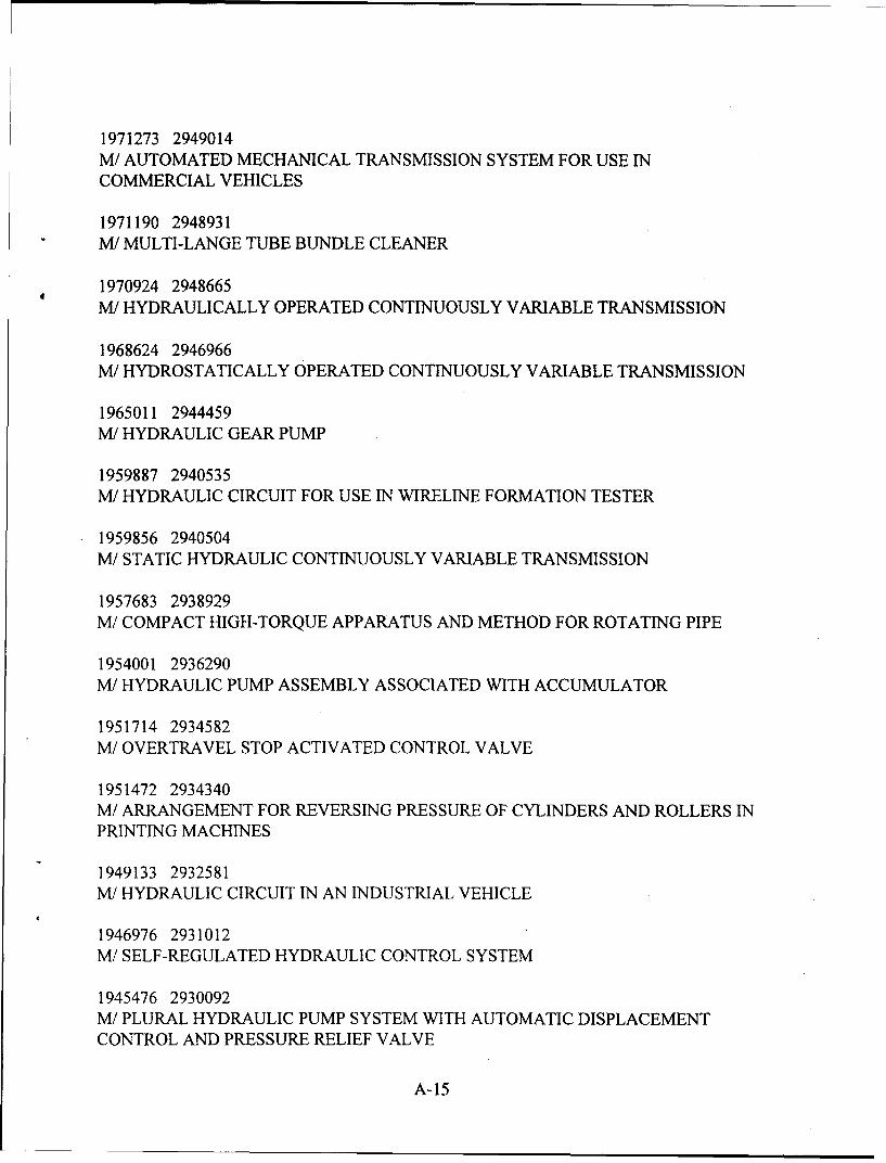
1971273 2949014M/ AUTOMATED MECHANICAL TRANSMISSION SYSTEM FOR USE INCOMMERCIAL VEHICLES
1971190 2948931M/ MULTI-LANGE TUBE BUNDLE CLEANER
1970924 2948665M/ HYDRAULICALLY OPERATED CONTINUOUSLY VARIABLE TRANSMISSION
1968624 2946966M/ HYDROSTATICALLY OPERATED CONTINUOUSLY VARIABLE TRANSMISSION
1965011 2944459M/ HYDRAULIC GEAR PUMP
1959887 2940535M/ HYDRAULIC CIRCUIT FOR USE IN WIRELINE FORMATION TESTER
1959856 2940504M/ STATIC HYDRAULIC CONTINUOUSLY VARIABLE TRANSMISSION
1957683 2938929M/ COMPACT HIGH-TORQUE APPARATUS AND METHOD FOR ROTATING PIPE
1954001 2936290M/ HYDRAULIC PUMP ASSEMBLY ASSOCIATED WITH ACCUMULATOR
1951714 2934582M/ OVERTRAVEL STOP ACTIVATED CONTROL VALVE
1951472 2934340M/ ARRANGEMENT FOR REVERSING PRESSURE OF CYLINDERS AND ROLLERS INPRINTING MACHINES
1949133 2932581M/ HYDRAULIC CIRCUIT IN AN INDUSTRIAL VEHICLE
1946976 2931012M/ SELF-REGULATED HYDRAULIC CONTROL SYSTEM
1945476 2930092M/ PLURAL HYDRAULIC PUMP SYSTEM WITH AUTOMATIC DISPLACEMENTCONTROL AND PRESSURE RELIEF VALVE
A-15

1945396 2930012M/ APPARATUS FOR FEEDING AND METERING FLUID COMPONENTS TO A HIGHPRESSURE MIXING HEAD
1942939 2928134M/ FLUID-PRESSURE ELEVATOR
1941152 2926925M/ ROTARY COMPRESSOR WITH CLUTCH AND BYPASS CONTROL ACTUATED BYHYDRAULIC FLUID
1936833 2923765M/ HYDRAULIC CONTINUOUS PRESS WITH IMPROVED DRIVE
1934190 2921700M/ TECHNIQUE FOR PROVIDING AN UNDERGROUND TUNNEL UTILIZING APOWERED BORING DEVICE
1923736 2914032M/ SUPERHIGH PRESSURE FLUID INJECTION APPARATUS
1907263 2901611M/ DOUBLE-ACTING FORGING HAMMER AND METHOD
2476001 3432664M/ HYDRAULIC PUMP OUTPUT PRESSURE COMPENSATION SYSTEM
2473486 3430703M/ HIGH PRESSURE VISCOUS LIQUID PUMP
A-16

Appendix B: Fenner Literature
B-1

(BLANK)

Toaly ilfre cea ad Woml telsaeor peole Hrcse n rdcs h ydraulicspmsad ooso
Fenner Water Hydraulics are playing a vital role in the drive against industrial pollution.Based on axial piston designs, and offering low-cost operation, minimum cooling, easy maintenance and reduced
system pressure losses, they are proving ideal for a wide variety of industrial uses.As a result of employing advanced materials, high velocity and loaded sliding surfaces are now able to operate
with water as their only lubricant, alleviating the need for an oil water interface and the possible contamination ofthe hydraulic system or the working environment.
Five sizes of pump and motor are now available. Future development includes tools, valves, circuit conditioning
- 4- .- -- -. D4. 4

ADVANTAGES;
v~~iS.SAFETY 0 Completely safe in pure form.
IPCA-notD Es;T FLUID COST N Cheap.
ISSoFvr A ,. IDOLS. ENVIRONMENTAL N No he. Ith orpollution risk.a Diot t'4) F10 SST~~s. LEALINSSU Maintenance witho ut mens.
a t.rv!N. TAt4SIlSAISO DISPOSAL U Down the drain.
,, w~ sS4NIZG. L flr*~ COMPATIBILITY U Safefor peopleprocesses anrdproducts.
f£ 0 ASSEM FS'.'G TE S STORAGE U On tap.
r 00 otI0LS EFFICIENCY N Reduced pressure losses in sysem.
* $UCLSA111ANTS. PBt PLsS4NG SEALING U Accidental lea kage not hazardous.
* UCA~~AND C4EMC COOLING N Often not required.
£ MErTALGLS COMPRESSIBILITY E Comparable with other hydrmaulicfuis
UW1N4C~ JRIVES-
F06~~~ 2 F6 T1() P3 ~120
-F06 ý2 15 2-60 *120~ 2
-DISPL-ACEME~ c e
>SPEED i 15150 50 150 /1500 .150
s1ELVE~lUIL Umft 92 40/4a 8103 10
-*-2228
/SPL,1M10 1410 2310.4
(1 -:br 19/
ES69/(2~VAUM~T MA~~ 33, '.21
. ;.'26.
Wbte~Y M 13eacmrhnieaplcufe~n
FA-0M82701599

Appendix C: Danfoss Literature
C-i

(BLANK)

Tech Note
Nessie' Motors - IType MAH 4/5 to 25/32
Introduction
Designand function
The MAH-motors are used when a rotat- The motors are designed so that theing movement is required. moving parts are water lubricated.The motors are based on the axial piston The motor is designed for ordinary water,principle, resulting in a very light and i.e. without additives of any kind to thecompact design compared to the output medium.power.
Advantages* High pressure level, 140 bar * Long life time* Very compact and light motor = > * All outside parts of the motor are made
higher degree of freedom when placing of non-corrosive material (special coat-the motor in a given application ed aluminium)
* No oil lubrication Owing to the smooth surfaces, it isMinimum service needed easy to clean the outside of the motor
Motor variantsSizes from 4 to 32 cm3/rev with 6 differ- The first size to be introduced is 10/12.5ent displacements are planned for the cm3/rev.MAH-motors.
1-1994 WN.20.A1.02

Technical data
MAHtype 4 5 10 12.5 25 32
Geometric displacemn. (Cml~rev) 10 12.5Max. speed (mm i' cant 3,000 3,000
Max. torque (Nm) cont 21.5 26. 5 :
Max. power (kW) cont 6.7 8.3
Max. pressure drop (bar) cont ..... 10 14
Max. water flow .ftmm) cant33 41
Startng torque (Nm) cont 14.3 17.8max. press. drop
Min. speed (rnin 1 ) 200 200
S*******,.*. 3.9 3.9Weight (kg). ........
Drain lineThe motor shall always be fitted with a Max. pressure in drain line: 5 bar.drain line.
Direction
of otaion The MAH motors are uni-directional, but The direction of rotation is decided to beavailable in both cw- and ccw-versions. the same as the outlet shaft's direction of
rotation, seen from the shaft towards themotor.
Please note: The motors are designed tobe able to turn "the opposite" directionfor a shorter period of time at a slightlylower efficiency.
2 WN.20.A1 .02 Subject to alteration without prior noticeS;.. ., *- - L ,.4 r% - A 14
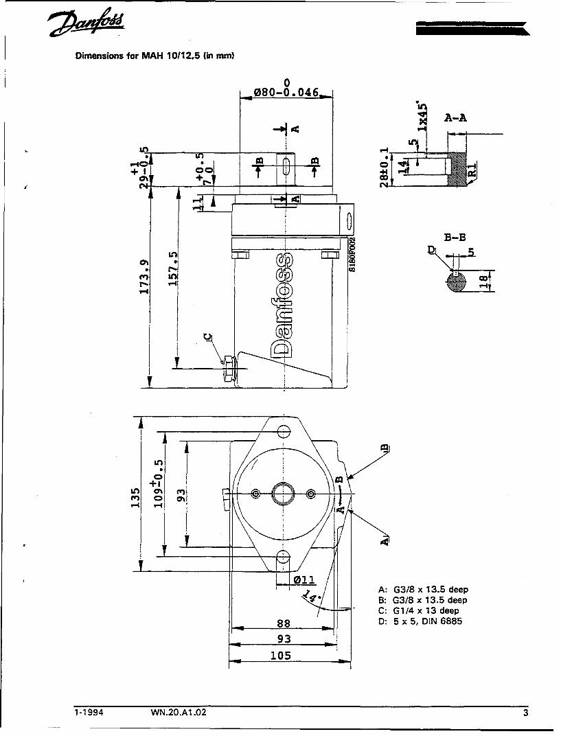
Dimensions for MAH 10/12.5 (in mm)
0
080-0. 046M-
* I
+ 1 0
B-B
+1
A: G3/8 x 13.5 deepB: G3/8 x 13.5 deepC: G1/4x13 deep
88________ D: 5 x 5, DIN 6885
105
1-1994 WN.20.A1 .02 3

Tech Note
Nessie' PumpsType PAH 25/32 and PAH 63/80
Introduction
ki
Designand function PAH 25/32 and 63/80 are pumps for estab- The pump is designed so that lubrication of
lishing flow under high water pressure. the moving parts of the pump follows fromthe water itself.
The pump is based on the axial pistonprinciple, which enables a very light and All parts included in the pump are designed for acompact design. long life time. This means a long life time with a
constant good efficiency, and in general aminimum of service is needed.
Advantages Very compact and light pump (can be Long life timeinstalled in direct connection with theelectrical motor) * All outside parts of the pump are made
of non-corrosive material (brass) and theMinimum service needed (periodic service surface is easy to cleanincluding oil changes and replacement ofwear parts disappears)
1-1994 WN.10.A1.02 1
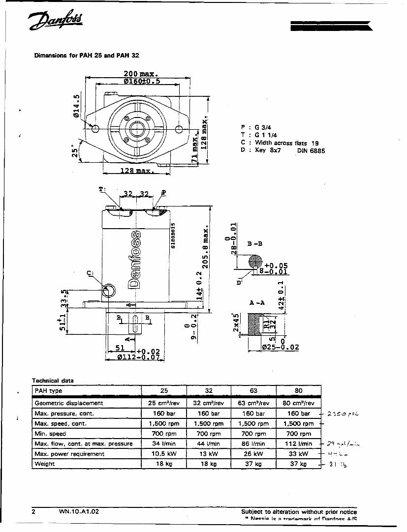
Dimensions for PAH 25 and PAH 32
200 max.016 Q-0.5
-, 74e --,7 N P: G 3/4
""C4 C Width across flats 19D Key 8x7 DIN 6885
_ 128 mx
T
42n
1 B -BCo CO'
4 _+0.05
C* Di -A -o•o
51 +0.0202-.21 812-0.0
Technical data______
PAH type 25 32 63 80
Geometric displacement 25 cm•/rev 32 cm3/rev 63 cm3/rev 80 cm 3/rev
Max. pressure, cont. 160 bar 160 bar 160 bar 160 bar •3•,;
Max. speed, cont. 1,500 rpm 1,500 rpm 1,500 rpm 1,500 rpm
Min. speed 700 rpm 700 rpm 700 rpm 700 rpm
Max. flow, cont. at max. pressure 34 I/min 44 I/mai 86 1/mai 112 1/maim 2 • •L!, /..
Max. power requirement 10,5 kW 13 kW 26 kW 33 kW • =o
Weight 18kg 18kg 37kg 37kg - 2 !
2 WN.IO.A1.02 Subject to alteration without prior notice
Mtsq +c1t1rmrrn4t~~fe !

Dimensions for PAHl 63 and PAH 80
242 max.
0200 _0.5
a
_ , P G. 1l1/4w T G 1l1/2
4 qC Width across flats 24
D Key 10x8 DIN 6885
160 max.
in B-B
+0. 050-0.01
A A-A gýi+1A'-,4 N'•
Co 32 -0.02~00
64 +0.020140 -0.07
1-1994 WN.10.A1.02 3

Mounting The pump is connected to the electrical motor by means of a bell-housing and an elasticcoupling on the input shaft.Direction of rotation is cw, seen from the shaft end.
- -
Connection Water supply to the pump can follow either The pressure at the pump inlet must be max.directly from the water supply or from a 5 bar abs and min. 0,9 bar abs to preventwater tank, placed above the pump. cavitation.
Filter The pump must be supplied with a lO In "hydraulic' applications, where the water
(6, = 75) water filter. is led back to a tank and recirculated, the filtershould be placed on the return line of the system.
In open-system applications (continuoussupply of *new* water), the filter must be Please contactthe Danfoss sales organisation forplaced in the pump inlet, further filter details.
Code numbers
PAH 25 180BOO06
PAH 32 180BOO05
PAH 63 180B0004
PAH 80 180B0003
4 WN.10.A1.02 Subject to alteration without prior notice
Appendix D: Sources Sought
D
D-1

(BLANK)
D-2

SYNOPSIS RESPONSE INFORMATION
SYNOPSIS NUMBER: N47408-94-R-9015
SUBJECT: SEAWATER HYDRAULIC MOTOR
Company Name: Allied Signal Inc.Address: 1300 W Warner Road
Tempe AZ 22200Company Size:Telephone Number: 602-893-5000FAX Number: 602-893-5123Point of Contact: James Hagerty
Company Name: Rotordynamics Seal ResearchAddress: 3628 Madison Avenue Suite 20
North Highlands CA 95660Company Size:Telephone Number: 916-344-9500FAX Number: 916-344-8400Point of Contact: Joseph Scharrer
Company Name:Address:
Company Size:Telephone Number: FAX Number:Point of Contact:
Company Name:Address:
Company Size:Telephone Number: FAX Number:Point of Contact:
Company Name:Address:
Company Size:Telephone Number: FAX Number:Point of Contact:
Company Name:Address:
Company Size:Telephone Number: FAX Number:Point of Contact:
D-3

Appendix E: Hydraulic Hose Comparisons
E-1

(BLANK)
E-2
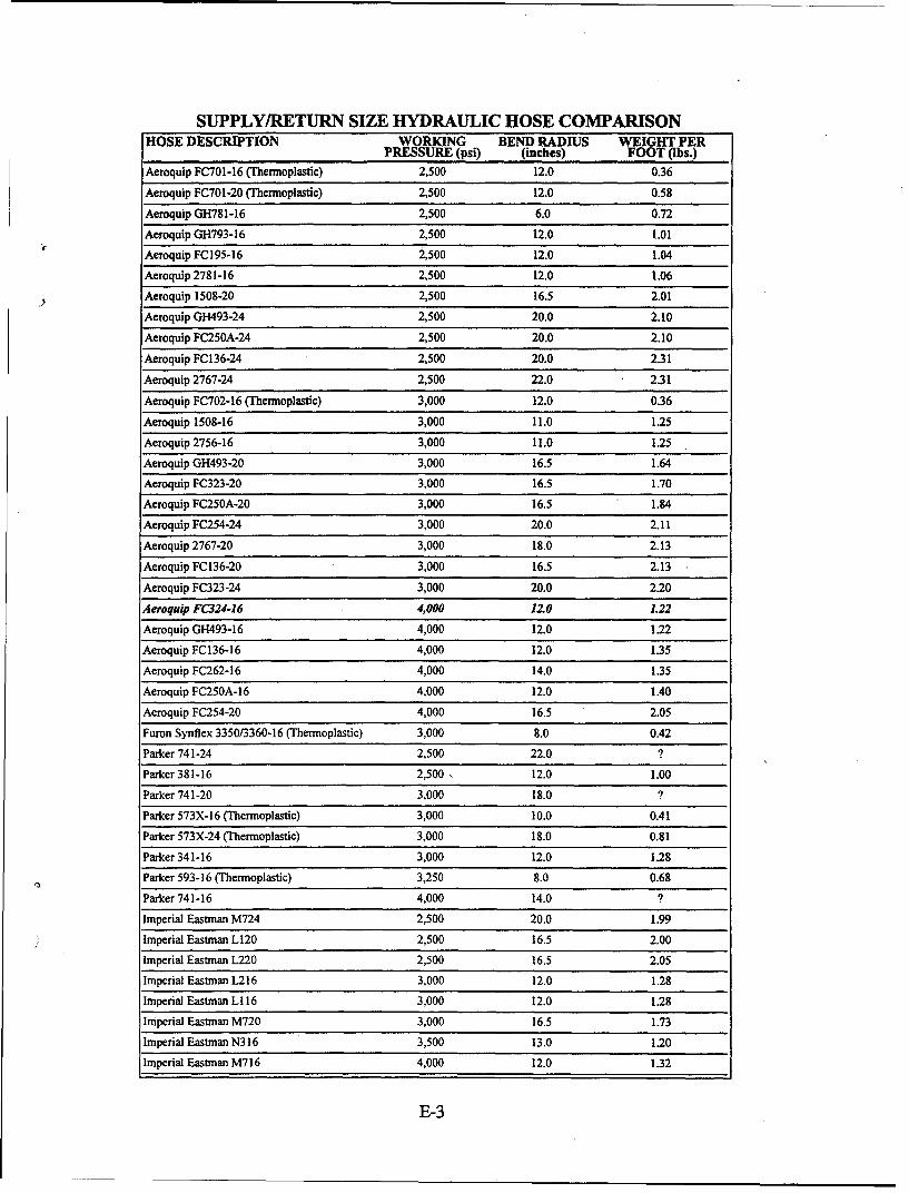
SUPPLY/RETURN SIZE HYDRAULIC HOSE COMPARISONHOSE DESCRIPTION WORKING BEND RADIUS WEIGHT PER
PRESSURE (psi) (inches) FOOT (Ibs.)
Aeroquip FC701-16 (Thermoplastic) 2,500 12.0 0.36
Aeroquip FC701-20 (Thermoplastic) 2,500 12.0 0.58
Aeroquip GH781-16 2,500 6.0 0.72
Aeroquip GH793-16 2,500 12.0 1.01
Aeroquip FC195-16 2,500 12.0 1.04
Aeroquip 2781-16 2,500 12.0 1.06
Aeroquip 1508-20 2,500 16.5 2.01
Aeroquip GH493-24 2,500 20.0 2.10
Aeroquip FC25OA-24 2,500 20.0 2.10
Aeroquip FC136-24 2,500 20.0 2.31
Aeroquip 2767-24 2,500 22.0 2.31
Aeroquip FC702-16 (Thermoplastic) 3,000 12.0 0.36
Aeroquip 1508-16 3,000 11.0 1.25
Aeroquip 2756-16 3,000 11.0 1.25
Aeroquip GH493-20 3,000 16.5 1.64
Aeroquip FC323-20 3,000 16.5 1.70
Aeroquip FC25OA-20 3,000 16.5 1.84
Aeroquip FC254-24 3,000 20.0 2.11
Aeroquip 2767-20 3,000 18.0 2.13
Aeroquip FC136-20 3,000 16.5 2.13
Aeroquip FC323-24 3,000 20.0 2.20
Aeroquip FC324-16 4,000 12.0 L22
Aeroquip GH493-16 4,000 12.0 1.22
Aeroquip FC136-16 4,000 12.0 1.35
Aeroquip FC262-16 4,000 14.0 1.35
Aeroquip FC250A-16 4,000 12.0 1.40
Aeroquip FC254-20 4,000 16.5 2.05
Furon Synflex 3350/3360-16 (Thermoplastic) 3,000 8.0 0.42
Parker 741-24 2,500 22.0 ?
Parker 381-16 2,500 12.0 1.00
Parker 741-20 3,000 18.0 ?
Parker 573X-16 (Thermoplastic) 3,000 10.0 0.41
Parker 573X-24 (Thermoplastic) 3,000 18.0 0.81
Parker 34 1-16 3,000 12.0 1.28
Parker 593-16 (Thermoplastic) 3,250 8.0 0.68
Parker 741-16 4,000 14.0 ?
Imperial Eastman M724 2,500 20.0 1.99
Imperial Eastman L120 2,500 16.5 2.00
Imperial Eastman L220 2,500 16.5 2.05
Imperial Eastman L216 3,000 12.0 1.28
Imperial Eastman L116 3,000 12.0 1.28
Imperial Eastman M720 3,000 16.5 1.73
Imperial Eastman N316 3,500 13.0 1.20
Imperial Eastman M716 4,000 12.0 1.32
E-3

CASE DRAIN SIZE HYDRAULIC HOSE COMPARISONHOSE DESCRIPTION WORKING BEND RADIUS WEIGHT PER
PRESSURE (psi) (inches) FOOT Qbs.)
Aeroquip FC390-08 (Thermoplastic) 2,500 3.5 0.16
Aeroquip FC690-08RL (Thermoplastic) 2,500 3.5 0.16
Aeroquip GH663-8 2,500 7.0 0.30
Aeroquip FC194-08 2,500 7.0 0.38
Aeroquip 2681-8 2,500 7.0 0.38
Aeroquip GH681-8 3,000 3.5 0.26
Aeroquip GH683-8 3,000 3.5 0.26
Aeroquip FC375-08 (Thermoplastic) 3,500 4.0 0.14
Aeroquip 374-08 3,500 4.0 0.14(Thermoplastic)
Aeroquip FC310-08 3,500 5.0 0.34
Aeroquip FC510-08 3,500 5.0 0.34
Aeroquip FC474-08 3,500 7.0 0.42
Aeroquip FC212-08 3,500 7.0 0.48
Aeroquip 2766-8 3,500 7.0 0.54
Aeroquip 1546-8 3,500 7.0 0.64
Furon Synflex 3350/3360-08 3,000 3.5 0.19(Thermoplastic)
Furon Synflex 3800-08 (Thermoplastic) 3,500 4.0 0.15
Furon Synflex 3R80-08 (Thermoplastic) 3,500 4.0 0.19
Furon Synflex 3580-08 3,500 3.3 0.21
Parker 53FR-8 (Thermoplastic) 2,500 3.0 0.18
Parker 560-8 (Thermoplastic) 2,500 3.3 0.20
Parker 580N-8 (Thermoplastic) 2,500 4.0 0.21
Parker 481-8 2,500 7.0 0.29
Parker 518C-8 (Thermoplastic) 3,000 3.0 0.15
Parker 53LT-8 (Thermoplastic) 3,000 3.5 0.19
Parker 520N-8 (Thermoplastic) 3,500 4.0 0.13
Parker 588N-8 (Thermoplastic) 3,500 4.0 0.21
Parker 590-8 (Thermoplastic) 3,500 3.3 0.25
Parker 301-8 3,500 7.0 0.45
Imperial Eastman HFS08 2,500 7.0 0.28
Imperial Eastman HRI C08 2,500 7.0 0.28
Imperial Eastman HR808/HR8008 3,500 7.0 0.17(Thermoplastic)
Imperial Eastman NJ408 3,500 7.0 0.45
Imperial Eastman J408 3,500 7.0 0.45
Imperial Eastman J908 3,500 7.0 0.45
Imperial Eastman H108 3,500 7.0 0.57
Imperial Eastman H408 3,500 7.0 0.59
E-4