report no.: gz10070050-1en2img.allhaving.com/upload/2505/download/1/pdf/3_3_4_61.pdf · supplied...
TRANSCRIPT


Report No.: GZ10070050-1
Page 2 of 42
CONTENT
TEST REPORT................................................................................................................................................................................. 1
CONTENT......................................................................................................................................................................................... 2
1 TEST RESULTS SUMMARY ............................................................................................................................................... 4
2 EMC RESULTS CONCLUSION .......................................................................................................................................... 5
3 LABORATORY MEASUREMENTS ................................................................................................................................... 6
4 EMI TEST................................................................................................................................................................................ 7
4.1 EN 55015 CONTINUOUS CONDUCTED DISTURBANCE VOLTAGE TEST .................................................................................. 7 4.1.1 Used Test Equipment .................................................................................................................................................. 7 4.1.2 Block Diagram of Test Setup....................................................................................................................................... 7 4.1.3 Test Setup and Procedure ........................................................................................................................................... 7 4.1.4 Test Data..................................................................................................................................................................... 8 4.1.5 Emission Curve ......................................................................................................................................................... 10 4.1.6 Measurement Uncertainty......................................................................................................................................... 11
4.2 EN 55015 RADIATED ELECTROMAGNETIC DISTURBANCE (9 KHZ-30 MHZ)....................................................................... 11 4.2.1 Used Test Equipment ................................................................................................................................................ 11 4.2.2 Block Diagram of Test Setup..................................................................................................................................... 11 4.2.3 Test Setup and Procedure ......................................................................................................................................... 11 4.2.4 Test Data................................................................................................................................................................... 12 4.2.5 Test Curve ................................................................................................................................................................. 13 4.2.6 Measurement Uncertainty......................................................................................................................................... 14
4.3 EN 55015 RADIATED ELECTROMAGNETIC DISTURBANCE (30 MHZ -300 MHZ, CDN METHOD) ........................................ 15 4.3.1 Used Test Equipment ................................................................................................................................................ 15 4.3.2 Block Diagram of Test Setup..................................................................................................................................... 15 4.3.3 Test Setup and Procedure ......................................................................................................................................... 15 4.3.4 Test Data................................................................................................................................................................... 16 4.3.5 Test Curve ................................................................................................................................................................. 17 4.3.6 Measurement uncertainty.......................................................................................................................................... 17
4.4 INSERTION LOSS.................................................................................................................................................................. 17
5 HARMONICS OF CURRENT ............................................................................................................................................ 18
5.1 USED TEST EQUIPMENT....................................................................................................................................................... 18 5.2 BLOCK DIAGRAM OF TEST SETUP ....................................................................................................................................... 18 5.3 TEST SETUP AND PROCEDURE ............................................................................................................................................. 18 5.4 TEST DATA.......................................................................................................................................................................... 19 5.5 MEASUREMENT UNCERTAINTY ........................................................................................................................................... 20
6 FLICKER............................................................................................................................................................................... 21
6.1 USED TEST EQUIPMENT....................................................................................................................................................... 21 6.2 BLOCK DIAGRAM OF TEST SETUP ....................................................................................................................................... 21 6.3 TEST SETUP AND PROCEDURE ............................................................................................................................................. 21
6.3.1 Definition .................................................................................................................................................................. 21 6.3.2 Test condition............................................................................................................................................................ 21
6.4 TEST DATA.......................................................................................................................................................................... 22 6.5 MEASUREMENT UNCERTAINTY ........................................................................................................................................... 22
7 EMS TEST............................................................................................................................................................................. 23
7.1 EN 61000-4-2(PURSUANT TO EN 61547) ELECTROSTATIC DISCHARGE IMMUNITY............................................................ 23 7.1.1 Used Test Equipment ................................................................................................................................................ 23 7.1.2 Block Diagram of Test Setup..................................................................................................................................... 24 7.1.3 Test Setup and Procedure ......................................................................................................................................... 24
Report No.: GZ10070050-1
Page 3 of 42
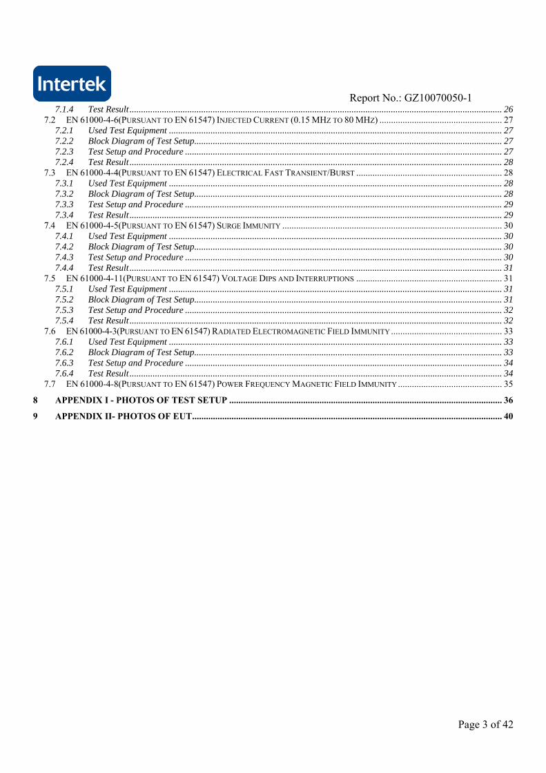
7.1.4 Test Result ................................................................................................................................................................. 26 7.2 EN 61000-4-6(PURSUANT TO EN 61547) INJECTED CURRENT (0.15 MHZ TO 80 MHZ) ..................................................... 27
7.2.1 Used Test Equipment ................................................................................................................................................ 27 7.2.2 Block Diagram of Test Setup..................................................................................................................................... 27 7.2.3 Test Setup and Procedure ......................................................................................................................................... 27 7.2.4 Test Result ................................................................................................................................................................. 28
7.3 EN 61000-4-4(PURSUANT TO EN 61547) ELECTRICAL FAST TRANSIENT/BURST ............................................................... 28 7.3.1 Used Test Equipment ................................................................................................................................................ 28 7.3.2 Block Diagram of Test Setup..................................................................................................................................... 28 7.3.3 Test Setup and Procedure ......................................................................................................................................... 29 7.3.4 Test Result ................................................................................................................................................................. 29
7.4 EN 61000-4-5(PURSUANT TO EN 61547) SURGE IMMUNITY ............................................................................................... 30 7.4.1 Used Test Equipment ................................................................................................................................................ 30 7.4.2 Block Diagram of Test Setup..................................................................................................................................... 30 7.4.3 Test Setup and Procedure ......................................................................................................................................... 30 7.4.4 Test Result ................................................................................................................................................................. 31
7.5 EN 61000-4-11(PURSUANT TO EN 61547) VOLTAGE DIPS AND INTERRUPTIONS ............................................................... 31 7.5.1 Used Test Equipment ................................................................................................................................................ 31 7.5.2 Block Diagram of Test Setup..................................................................................................................................... 31 7.5.3 Test Setup and Procedure ......................................................................................................................................... 32 7.5.4 Test Result ................................................................................................................................................................. 32
7.6 EN 61000-4-3(PURSUANT TO EN 61547) RADIATED ELECTROMAGNETIC FIELD IMMUNITY................................................ 33 7.6.1 Used Test Equipment ................................................................................................................................................ 33 7.6.2 Block Diagram of Test Setup..................................................................................................................................... 33 7.6.3 Test Setup and Procedure ......................................................................................................................................... 34 7.6.4 Test Result ................................................................................................................................................................. 34
7.7 EN 61000-4-8(PURSUANT TO EN 61547) POWER FREQUENCY MAGNETIC FIELD IMMUNITY............................................. 35
8 APPENDIX I - PHOTOS OF TEST SETUP ...................................................................................................................... 36
9 APPENDIX II- PHOTOS OF EUT...................................................................................................................................... 40
Report No.: GZ10070050-1
Page 4 of 42
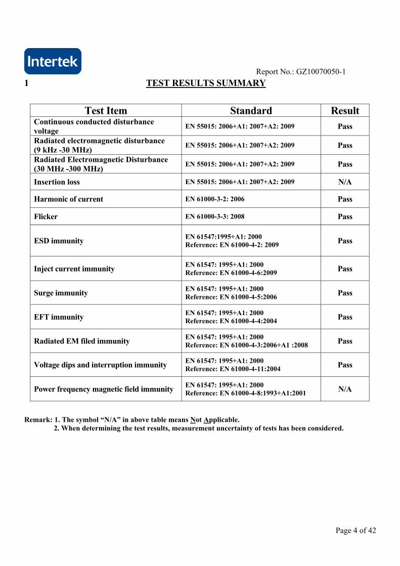
1 TEST RESULTS SUMMARY
Test Item Standard Result
Continuous conducted disturbance voltage
EN 55015: 2006+A1: 2007+A2: 2009 Pass
Radiated electromagnetic disturbance (9 kHz -30 MHz)
EN 55015: 2006+A1: 2007+A2: 2009 Pass
Radiated Electromagnetic Disturbance (30 MHz -300 MHz)
EN 55015: 2006+A1: 2007+A2: 2009 Pass
Insertion loss EN 55015: 2006+A1: 2007+A2: 2009 N/A
Harmonic of current EN 61000-3-2: 2006 Pass
Flicker EN 61000-3-3: 2008 Pass
ESD immunity EN 61547:1995+A1: 2000 Reference: EN 61000-4-2: 2009 Pass
Inject current immunity EN 61547: 1995+A1: 2000 Reference: EN 61000-4-6:2009 Pass
Surge immunity EN 61547: 1995+A1: 2000 Reference: EN 61000-4-5:2006 Pass
EFT immunity EN 61547: 1995+A1: 2000 Reference: EN 61000-4-4:2004 Pass
Radiated EM filed immunity EN 61547: 1995+A1: 2000 Reference: EN 61000-4-3:2006+A1 :2008 Pass
Voltage dips and interruption immunity EN 61547: 1995+A1: 2000 Reference: EN 61000-4-11:2004 Pass
Power frequency magnetic field immunity EN 61547: 1995+A1: 2000 Reference: EN 61000-4-8:1993+A1:2001 N/A
Remark: 1. The symbol “N/A” in above table means Not Applicable. 2. When determining the test results, measurement uncertainty of tests has been considered.

Report No.: GZ10070050-1
Page 5 of 42
2 EMC Results Conclusion (with Justification)
RE: EMC Testing Pursuant to EMC Directive 2004/108/EC Performed on the d.c. or a.c.
supplied electronic controlgear for LED modules (LED Driver), Models: ELP30-12LS. We tested the d.c. or a.c. supplied electronic controlgear for LED modules (LED Driver), Model: ELP30-12LS, to determine if it was in compliance with the relevant EN standards as marked on the Test Results Summary. We found that the unit met the requirement of EN 55015, EN 61000-3-2, EN 61000-3-3, EN 61547 (EN 61000-4-2), EN 61547 (EN 61000-4-4), EN 61547 (EN 61000-4-6), EN 61547 (EN 61000-4-5), EN 61547 (EN 61000-4-11), & EN 61547 (EN 61000-4-3) standards when tested as received. The worst case’s test data was presented in this test report. Test item Radiated EM filed immunity were subcontracted. The production units are required to conform to the initial sample as received when the units are placed on the market.

Report No.: GZ10070050-1
Page 6 of 42
3 LABORATORY MEASUREMENTS
Configuration Information Equipment Under Test (EUT): d.c. or a.c. supplied electronic controlgear for LED
modules (LED Driver) Model: ELP30-12LS Serial No. Not Labelled Support Equipment: Resistance provided by Intertek Rated Voltage: 220-240 VAC; 50/60 Hz Condition of Environment: Temperature : 15~25C
Relative Humidity: 35~60% Atmosphere Pressure 86~106kPa
Notes: 1. The EMI measurements had been made in the operating mode produced the largest emission in the frequency band being investigated consistent with normal applications. An attempt had been made to maximize the emission by varying the configuration of the EUT. 2. The EMS measurements had been made in the frequency bands being investigated, with the EUT in the most susceptible operating mode consistent with normal applications. The configuration of the test sample had been varied to achieve maximum susceptibility.

Report No.: GZ10070050-1
Page 7 of 42
4 EMI TEST
4.1 EN 55015 Continuous Conducted Disturbance Voltage Test
Test Result: Pass
4.1.1 Used Test Equipment
Equipment No. Equipment Model Manufacturer EM080-05 EMI receiver ESCI R&S EM006-05 LISN ENV216 R&S EM004-03 EMC shield Room 8m×4m×3m Zhongyu
4.1.2 Block Diagram of Test Setup
4.1.3 Test Setup and Procedure The EUT was set to achieve the maximum emission level. The mains terminal disturbance voltage was measured with the EUT in a shielded room. The EUT was connected to AC power source through an Artificial Mains Network which provide a 50 linear impedance Artificial hand is used if appropriate (for handheld apparatus). The load/control terminal disturbance voltage was measured with passive voltage probe if appropriate.
The EUT was placed on a 0.4m high non-metallic table above a metallic plane, and 0.4m from wall of shielded room which is considered as Ground Reference Plane (GRP) (For floor standing EUT, was placed on a 0.1m high non-metallic supported on GRP) The EUT keeps a distance of at least 0.8m from any other of the metallic surface. The Artificial Mains Network is situated at a distance of 0.8m from the EUT.
During the test, mains lead of EUT excess 0.8m was folded back and forth parallel to the lead so as to form a horizontal bundle with a length between 0.3m and 0.4m.
The bandwidth of test receiver was set at 200Hz in the frequency range from 9kHz to 150KHz, and 9kHz in the frequency range from 150kHz to 30MHz.
AC Power Source
TRANSFORMER AMN EUT
TEST RECEIVER
Passive voltage
50 terminator
AE

Report No.: GZ10070050-1
Page 8 of 42
4.1.4 Test Data
At main terminal: Pass
Tested Wire: Live Operation Mode: EUT on EDIT PEAK LIST (Final Measurement Results)
Trace1: CE1511QP
Trace2: CE1511AV
Trace3: ---
TRACE FREQUENCY LEVEL dBµV DELTA LIMIT dB
2 Average 9.64 kHz 53.17 L1
2 Average 12.84 kHz 81.58 L1
2 Average 25.64 kHz 53.05 L1
2 Average 35.16 kHz 54.21 L1
1 Quasi Peak 44.04 kHz 86.07 L1 -23.92
2 Average 44.04 kHz 82.48 L1
1 Quasi Peak 88.12 kHz 62.99 L1 -21.84
2 Average 88.12 kHz 59.64 L1
2 Average 88.92 kHz 56.55 L1
2 Average 91.24 kHz 57.33 L1
2 Average 132.36 kHz 47.04 L1
2 Average 133.24 kHz 38.59 L1
2 Average 133.88 kHz 40.54 L1
1 Quasi Peak 154 kHz 60.12 L1 -5.65
2 Average 154 kHz 41.22 L1 -14.56
2 Average 178 kHz 46.49 L1 -8.08
2 Average 222 kHz 37.36 L1 -15.37
1 Quasi Peak 310 kHz 44.65 L1 -15.32
2 Average 310 kHz 31.85 L1 -18.11
1 Quasi Peak 386 kHz 40.40 L1 -17.74 1 Quasi Peak 458 kHz 39.68 L1 -17.03
2 Average 1.546 MHz 36.52 L1 -9.47
1 Quasi Peak 1.554 MHz 47.35 L1 -8.64
1 Quasi Peak 1.722 MHz 43.53 L1 -12.46
1 Quasi Peak 2.994 MHz 33.91 L1 -22.08
1 Quasi Peak 3.09 MHz 40.21 L1 -15.78
1 Quasi Peak 3.262 MHz 36.25 L1 -19.74
1 Quasi Peak 3.434 MHz 33.27 L1 -22.72
1 Quasi Peak 3.654 MHz 33.01 L1 -22.98
1 Quasi Peak 3.878 MHz 33.15 L1 -22.85
1 Quasi Peak 6.162 MHz 38.94 L1 -21.05
1 Quasi Peak 8.506 MHz 34.36 L1 -25.63

Report No.: GZ10070050-1
Page 9 of 42
Tested Wire: Neutral Operation Mode: EUT on
EDIT PEAK LIST (Final Measurement Results)
Trace1: CE1511QP
Trace2: CE1511AV
Trace3: ---
TRACE FREQUENCY LEVEL dBµV DELTA LIMIT dB
2 Average 9 kHz 54.67 L1
2 Average 12.76 kHz 60.97 L1
2 Average 25.64 kHz 51.75 L1
2 Average 35.08 kHz 55.11 L1
1 Quasi Peak 44.6 kHz 89.12 L1 -20.87
2 Average 44.6 kHz 85.50 L1
2 Average 45.24 kHz 81.75 L1
2 Average 80.28 kHz 47.67 L1
1 Quasi Peak 89 kHz 65.08 L1 -19.66
2 Average 89 kHz 61.62 L1
2 Average 89.8 kHz 56.52 L1
1 Quasi Peak 89.88 kHz 62.14 L1 -22.52
2 Average 90.36 kHz 56.71 L1
2 Average 94.12 kHz 50.24 L1
2 Average 94.68 kHz 50.95 L1
2 Average 95.96 kHz 49.59 L1
2 Average 133.48 kHz 46.42 L1
2 Average 134.36 kHz 43.31 L1
1 Quasi Peak 150 kHz 35.65 L1 -44.34
2 Average 182 kHz 45.67 L1 -8.72 1 Quasi Peak 314 kHz 46.35 L1 -13.50
1 Quasi Peak 322 kHz 45.25 L1 -14.40
1 Quasi Peak 1.41 MHz 48.27 L1 -7.72
1 Quasi Peak 2.006 MHz 42.68 L1 -13.31
1 Quasi Peak 3.018 MHz 38.32 L1 -17.68
1 Quasi Peak 3.11 MHz 40.33 L1 -15.66
1 Quasi Peak 3.286 MHz 40.96 L1 -15.03
1 Quasi Peak 3.734 MHz 39.46 L1 -16.53
1 Quasi Peak 3.906 MHz 39.71 L1 -16.28
1 Quasi Peak 5.422 MHz 37.68 L1 -22.31
1 Quasi Peak 7.15 MHz 41.04 L1 -18.95
1 Quasi Peak 8.386 MHz 37.43 L1 -22.56
At load/control terminal: Not Applicable
Report No.: GZ10070050-1
Page 10 of 42
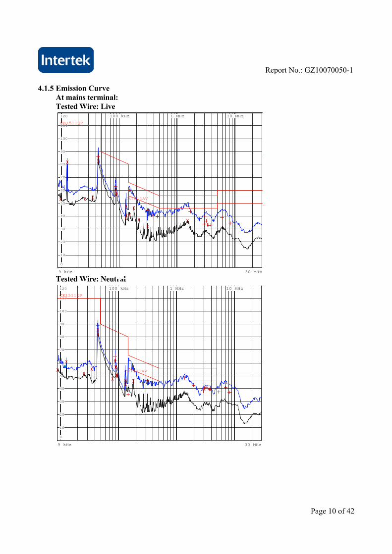
4.1.5 Emission Curve
At mains terminal: Tested Wire: Live
9 kHz 30 MHz
T
6A
100 kHz 1 MHz 10 MHz
0
10
20
30
40
50
60
70
80
90
100
110
120
CE1511AV
CE1511QP
Tested Wire: Neutral
9 kHz 30 MHz
100 kHz 1 MHz 10 MHz
0
10
20
30
40
50
60
70
80
90
100
110
120
1
CE1511AV
CE1511QP

Report No.: GZ10070050-1
Page 11 of 42
At load/control terminal:
Not Applicable.
4.1.6 Measurement Uncertainty The measurement uncertainty describes the overall uncertainty of the given measured value during the operation of the EUT. Measurement uncertainty is calculated in accordance with CISPR 16-4-2:2003. Measurement uncertainty of mains terminal disturbance voltage in CISPR band A: 1.5dB. Measurement uncertainty of mains terminal disturbance voltage in CISPR band B: 2.5dB. The measurement uncertainty is given with a confidence of 95%, k=2.
4.2 EN 55015 Radiated Electromagnetic Disturbance (9 kHz-30 MHz)
Test Result: Pass
4.2.1 Used Test Equipment
Equipment No. Equipment Model Manufacturer EM080-05 EMI receiver ESCI R&S EM061-04 Triple Loop Antenna HXYZ9170 SCHWARZBECK EM004-03 EMC shield Room 8m×4m×3m Zhongyu
4.2.2 Block Diagram of Test Setup Loop Antenna
Ferrite absorber 4.2.3 Test Setup and Procedure
The EUT is placed in the centre of the loop antenna system(LAS). The current induced by the magnetic field from the EUT into each of the three large loop antennas of the LAS is measured by connecting the current probe of the large loop antenna to a measuring receiver. During the measurements the EUT remains in a fixed position. The currents in the three large loop antenna, origination from the three mutually orthogonal magnetic field components, are measured in sequence. Each current level measured shall comply with the emission limit, expressed in dBμA, as specified in table of EN 55015. The distance between the outer perimeter of the LAS and nearby objects, such as floor and walls, shall be at least 0.5m.
EUT
Receiver
Coaxial switch

Report No.: GZ10070050-1
Page 12 of 42
To avoid unwanted capacitive coupling between the EUT and the LAS, the maximum dimensions of the EUT shall allow a distance of at least 0.2m between the EUT and the standardized 2m large loop antenna of the LAS. The position of the mains lead shall be optimized for maximum current induction. In general, this position will not be critical when the EUT complies with the conducted emission limit.
4.2.4 Test Data
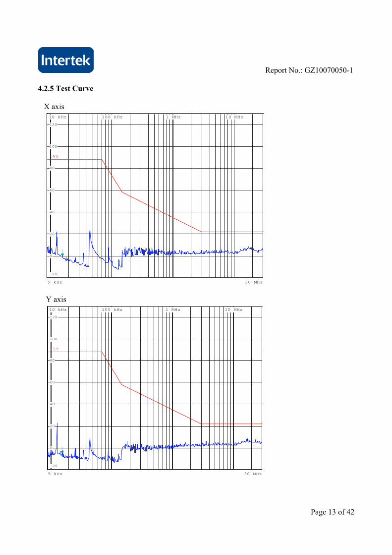
Frequency X axis Y axis Z axis Limit
[MHz] [dB(μA)] [dB(μA)] [dB(μA)] [dB(μA)]0.009 <78 <78 <78 88.00.050 <78 <78 <78 88.00.100 <64 <64 <64 74.00.160 <47 <47 <47 57.20.240 <40 <40 <40 52.40.550 <30 <30 <30 42.51.000 <25 <25 <25 35.41.400 <20 <20 <20 31.42.000 <17 <17 <17 27.13.500 <12 <12 <12 22.06.000 <12 <12 <12 22.0
10.000 <12 <12 <12 22.022.000 <12 <12 <12 22.030.000 <12 <12 <12 22.0
Report No.: GZ10070050-1
Page 13 of 42
4.2.5 Test Curve X axis
9 kHz 30 MHz
10 kHz 100 kHz 1 MHz 10 MHz
-20
0
20
40
60
80
100
120
1
15X
Y axis
6
9 kHz 30 MHz
T
A
10 kHz 100 kHz 1 MHz 10 MHz
-20
0
20
40
60
80
100
120
1
15Y

Report No.: GZ10070050-1
Page 14 of 42
Z axis
6
9 kHz 30 MHz
T
A
10 kHz 100 kHz 1 MHz 10 MHz
-20
0
20
40
60
80
100
120
1
15Z
4.2.6 Measurement Uncertainty The measurement uncertainty for induction current is under consideration according to CISPR 16-4-2:2003.
Report No.: GZ10070050-1
Page 15 of 42
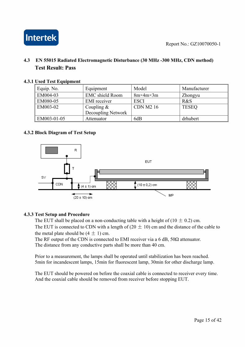
4.3 EN 55015 Radiated Electromagnetic Disturbance (30 MHz -300 MHz, CDN method)
Test Result: Pass
4.3.1 Used Test Equipment
Equip. No. Equipment Model Manufacturer EM004-03 EMC shield Room 8m×4m×3m Zhongyu EM080-05 EMI receiver ESCI R&S EM003-02 Coupling &
Decoupling Network CDN M2 16 TESEQ
EM003-01-05 Attenuator 6dB drhubert
4.3.2 Block Diagram of Test Setup
4.3.3 Test Setup and Procedure The EUT shall be placed on a non-conducting table with a height of (10 ± 0.2) cm. The EUT is connected to CDN with a length of (20 ± 10) cm and the distance of the cable to the metal plate should be (4 ± 1) cm. The RF output of the CDN is connected to EMI receiver via a 6 dB, 50Ω attenuator. The distance from any conductive parts shall be more than 40 cm. Prior to a measurement, the lamps shall be operated until stabilization has been reached. 5min for incandescent lamps, 15min for fluorescent lamp, 30min for other discharge lamp. The EUT should be powered on before the coaxial cable is connected to receiver every time. And the coaxial cable should be removed from receiver before stopping EUT.
Report No.: GZ10070050-1
Page 16 of 42
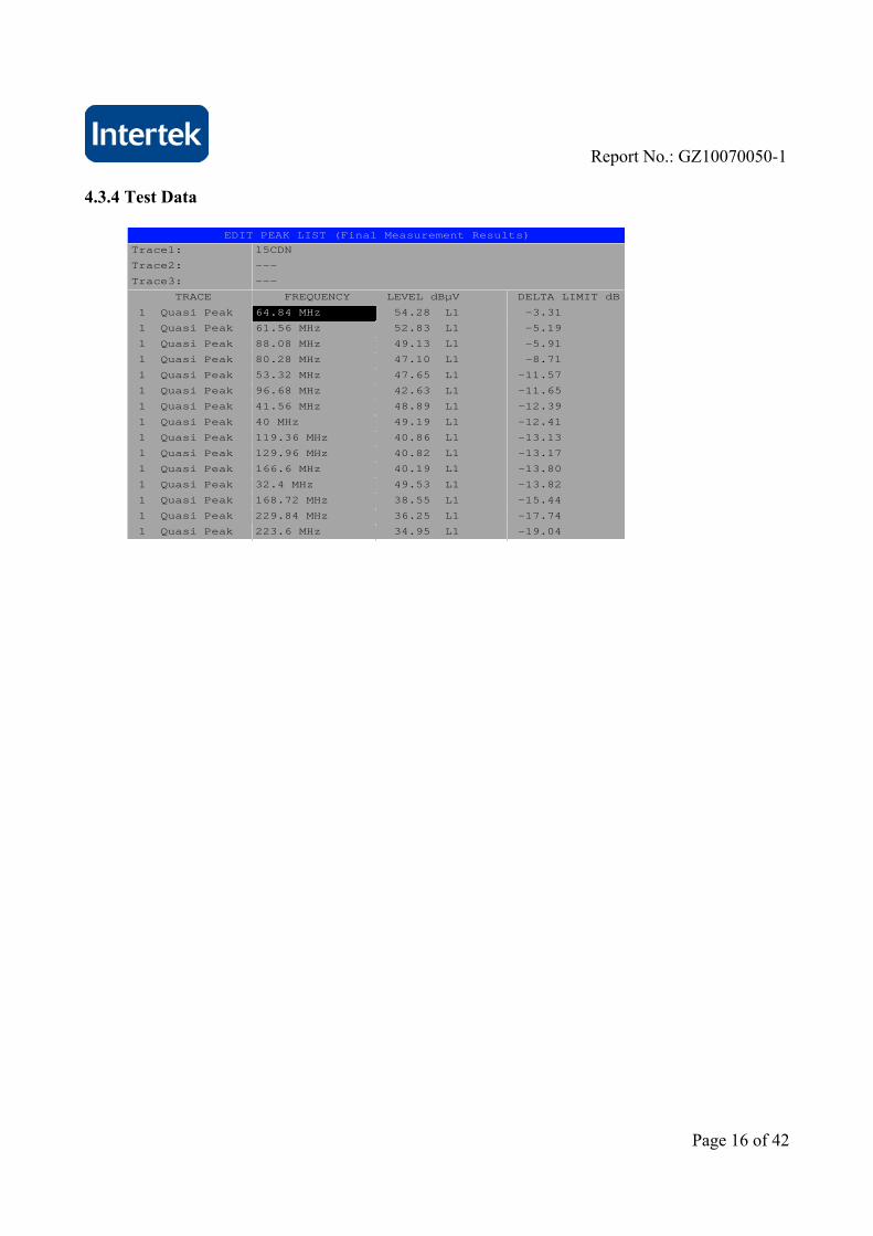
4.3.4 Test Data
EDIT PEAK LIST (Final Measurement Results)
Trace1: 15CDN
Trace2: ---
Trace3: ---
TRACE FREQUENCY LEVEL dBµV DELTA LIMIT dB
1 Quasi Peak 64.84 MHz 54.28 L1 -3.31
1 Quasi Peak 61.56 MHz 52.83 L1 -5.19
1 Quasi Peak 88.08 MHz 49.13 L1 -5.91
1 Quasi Peak 80.28 MHz 47.10 L1 -8.71
1 Quasi Peak 53.32 MHz 47.65 L1 -11.57
1 Quasi Peak 96.68 MHz 42.63 L1 -11.65
1 Quasi Peak 41.56 MHz 48.89 L1 -12.39
1 Quasi Peak 40 MHz 49.19 L1 -12.41
1 Quasi Peak 119.36 MHz 40.86 L1 -13.13
1 Quasi Peak 129.96 MHz 40.82 L1 -13.17
1 Quasi Peak 166.6 MHz 40.19 L1 -13.80
1 Quasi Peak 32.4 MHz 49.53 L1 -13.82
1 Quasi Peak 168.72 MHz 38.55 L1 -15.44
1 Quasi Peak 229.84 MHz 36.25 L1 -17.74
1 Quasi Peak 223.6 MHz 34.95 L1 -19.04

Report No.: GZ10070050-1
Page 17 of 42
4.3.5 Test Curve
30 MHz 300 MHz
T
6A
100 MHz
-10
0
10
20
30
40
50
60
70
80
90
1
15CDN
4.3.6 Measurement uncertainty
The measurement uncertainty for Radiated Electromagnetic Disturbance t (30 MHz -300 MHz, CDN method) is under consideration according to CISPR 16-4-2:2003.
4.4 Insertion Loss
Test Result: Not Applicable. Remark: Not required by standard.

Report No.: GZ10070050-1
Page 18 of 42
5 Harmonics of current Test Result: Pass
5.1 Used Test Equipment
Equipment No. Equipment Model Manufacturer EM001-02
Harmonic & Flicker Test System
5001IX-CTS-400-413
California Instrument
5.2 Block Diagram of Test Setup
5.3 Test Setup and Procedure
Harmonics of the fundamental current were measured up to 40 order harmonics using a digital power meter with an analogue output and frequency analyser which was integrated in the harmonic & flicker test system. The measurements were carried out under steady conditions. EUT is not discharge lighting, the harmonics currents limits are not specified for the equipment with a rated power smaller than or equal to 25W. Therefore the EUT was deemed fulfill the requirements of relative standard without testing.
Harmonic & flicker test system EUT
AE

Report No.: GZ10070050-1
Page 19 of 42
5.4 Test Data Harmonics – Class-C per Ed. 3.0 (incl. inter-harmonics)
Current & voltage waveforms
-0.3
-0.2
-0.1
0.0
0.1
0.2
0.3
-300
-200
-100
0
100
200
300
Cu
rre
nt (A
mp
s)V
olta
ge
(Vo
lts)
Harmonics and Class C limit line European Limits
0.00
0.01
0.02
0.03
0.04
0.05
0.06
Cu
rre
nt R
MS
(Am
ps)
Harmonic #4 8 12 16 20 24 28 32 36 40
Test result: Pass Worst harmonic was #5 with 88.01% of the limit.

Report No.: GZ10070050-1
Page 20 of 42
Current Test Result Summary (Run time)
Test Result: Pass Source qualification: Normal Highest parameter values during test:
V_RMS (Volts): 230.25 Frequency(Hz): 50.00 I_Peak (Amps): 0.271 I_RMS (Amps): 0.153 I_Fund (Amps): 0.149 Crest Factor: 1.770 Power (Watts): 33.6 Power Factor: 0.954
Harm# Harms(avg) 100%Limit %of Limit Harms(max) 150%Limit %of Limit Status 2 0.001 0.003 34.2 0.001 0.004 25.78 Pass 3 0.017 0.043 40.6 0.018 0.064 28.32 Pass 4 0.000 5 0.013 0.015 88.0 0.014 0.022 60.52 Pass 6 0.000 7 0.009 0.010 82.8 0.009 0.016 57.13 Pass 8 0.000 9 0.001 0.007 17.0 0.001 0.011 12.57 Pass 10 0.000 11 0.002 0.004 49.9 0.002 0.007 37.22 Pass 12 0.000 13 0.002 0.004 37.4 0.002 0.007 27.23 Pass 14 0.000 15 0.000 0.004 7.1 0.000 0.007 5.57 Pass 16 0.000 17 0.001 0.004 22.2 0.001 0.007 17.81 Pass 18 0.000 19 0.001 0.004 16.2 0.001 0.007 12.58 Pass 20 0.000 21 0.000 0.004 10.8 0.001 0.007 8.30 Pass 22 0.000 23 0.001 0.004 13.6 0.001 0.007 10.97 Pass 24 0.000 25 0.000 0.004 8.5 0.000 0.007 7.41 Pass 26 0.000 27 0.000 0.004 11.0 0.001 0.007 8.44 Pass 28 0.000 29 0.000 0.004 10.0 0.001 0.007 8.10 Pass 30 0.000 31 0.000 0.004 5.4 0.000 0.007 4.91 Pass 32 0.000 33 0.000 0.004 10.1 0.001 0.007 7.73 Pass 34 0.000 35 0.000 0.004 9.4 0.000 0.007 7.18 Pass 36 0.000 37 0.000 0.004 5.3 0.000 0.007 5.27 Pass 38 0.000 39 0.000 0.004 9.7 0.001 0.007 8.39 Pass 40 0.000
5.5 Measurement Uncertainty
The measurement uncertainty for harmonic test is under consideration according to CISPR 16-4-2:2003.

Report No.: GZ10070050-1
Page 21 of 42
6 Flicker Test Result: Pass
6.1 Used Test Equipment
Equipment No. Equipment Model Manufacturer EM001-02
Harmonic & Flicker Test System
5001IX-CTS-400-413
California Instrument
6.2 Block Diagram of Test Setup
6.3 Test Setup and Procedure
6.3.1 Definition Flicker: impression of unsteadiness of visual sensation induced by a lighting stimulus
whose luminance or spectral distribution fluctuates with time. Pst: Short-term flicker indicator The flicker severity evaluated over a short period
(in minutes); Pst=1 is the conventional threshold of irritability Plt: long-term flicker indicator; the flicker severity evaluated over a long period
(a few hous). Using successive Pst valuse. dc: the relative steady-state voltage change dmax: the maximum relative voltage change d(t): the value during a voltage change
6.3.2 Test condition The EUT was set to produce the most unfavourable sequence of voltage changes.
Harmonic & flicker test system EUT
AE
Report No.: GZ10070050-1
Page 22 of 42
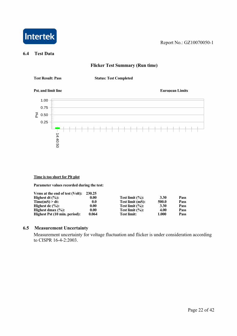
6.4 Test Data
Flicker Test Summary (Run time)
Test Result: Pass Status: Test Completed Psti and limit line European Limits
0.25
0.50
0.75
1.00
Pst
14:4
0:5
0
Time is too short for Plt plot Parameter values recorded during the test: Vrms at the end of test (Volt): 230.25 Highest dt (%): 0.00 Test limit (%): 3.30 Pass Time(mS) > dt: 0.0 Test limit (mS): 500.0 Pass Highest dc (%): 0.00 Test limit (%): 3.30 Pass Highest dmax (%): 0.00 Test limit (%): 4.00 Pass Highest Pst (10 min. period): 0.064 Test limit: 1.000 Pass
6.5 Measurement Uncertainty
Measurement uncertainty for voltage fluctuation and flicker is under consideration according to CISPR 16-4-2:2003.

Report No.: GZ10070050-1
Page 23 of 42
7 EMS TEST Performance Criteria:
Criterion A: During the test no change of the luminous intensity shall be observed and the regulating control, if any, shall operate during the test as intended.
Criterion B: During the test the luminous intensity may change to any value. After the test the luminous intensity shall be restored to its initial value within 1 min.
Regulating controls need not function during the test, but after the test the mode of the control shall be the same as before the test provided that during the test no mode changing commands were given.
Criterion C: During and after the test any change of the luminous intensity is allowed and the lamp(s) may be extinguished. After the test, within 30 min, all functions shall return to normal if necessary by temporary interruption of the mains supply and /or operating the regulating control.
Additional requirement for lighting equipment incorporation a starting device:
After the test the lighting equipment is switched off. After half an hour it is witched on again. The lighting equipment shall start and operate as intended.
Measurement Uncertainty According to CISPR 16-4-2:2003, measurement uncertainty to immunity test is under consideration. Note: “N/A” means Not Applicable in below text.
7.1 EN 61000-4-2(Pursuant to EN 61547) Electrostatic Discharge Immunity
Performance criterion: B Test Result: Pass
7.1.1 Used Test Equipment
Equip. No. Equipment Model Manufacturer EM077-02 ESD Simulator NSG435 SCHAFFNER

Report No.: GZ10070050-1
Page 24 of 42
7.1.2 Block Diagram of Test Setup
Note: HCP means Horizontal Coupling Plane, VCP means Vertical Coupling Plane GRP means Ground Reference Plane
7.1.3 Test Setup and Procedure
The EUT was put on a (0,8 0,08) m high wooden tabel/0.1m high for floor standing equipment standing on the ground reference plane(GRP) 3m by 2m in size, made by iron 1.0 mm thick. A horizontal coupling plane(HCP) (1,6 0,02) m by (0,8 0,02) m in size was placed on the table, and the EUT with its cables were isolated from the HCP by an insulating support with (0.50.05)mm thick. The VCP 0.5m by 0.5m in size & HCP were constructed from the same material type & thinkmess as that of the GRP, and connected to the GRP via a 470k resistor at each end.
For floor standing equipment, The EUT shall be isolated from the ground reference plane by an insulating support of 0,05 mto 0,15 m thick. The EUT cables shall be isolated from the ground reference plane by an insulating support of (0,5 ± 0,05) mm. This cable isolation shall extend beyond the edge of the EUT isolation.
The distance between EUT and any of the other metallic surface excepted the GRP, HCP & VCP was greater than 0.8m.
The EUT was arranged and connected according to its functional requirements.
Direct static electricity discharges was applied only to those points and surface which are accessible to personnel during normal usage, terminals are excluded.
On each preselected points 10 times of each polarity single discharge were applied .
Immunity system
EUT ESD simulator
VCP
HCP
Insulate Support
GRP
470kResist

Report No.: GZ10070050-1
Page 25 of 42
The ESD generator was held perpendicular to the surface to which the discharge is applied.
The discharge return cable of the generator was kept at a distance of 0.2m whilst the discharge is being applied. During the contact discharges, the tip of the discharge electrode was touch the EUT before the discharge switch is operated. During the air discharges, the round discharge tip of the discharge electrode was approached as fast as possible to touch the EUT.
Indirect discharge was conducted to objects placed near the EUT, simulated by applying the dischares of the ESD generator to a coupling plane, in the contact discharge mode.
After each discharge, the ESD generator was removed from the EUT, the generator is then retriggered for a new single discharge. For ungrounded product, a grounded carbon fibre brush with bleeder resistors (2×470 kΩ) in the grounding cable was used after each discharge to remove remnant electrostatic voltage.
10 times of each polarity single discharge were applied to HCP and VCP. The detail selected points are listed in the following table.

Report No.: GZ10070050-1
Page 26 of 42
7.1.4 Test Result
Direct Application of ESD
Direct Contact Discharge
Applied Voltage
(kV)
No. of Discharge for each point
Result (Pursuant to EN 61547)
Discharged Points
4 20 N/A All touchable screws of enclosure, accessible metal parts of the EUT
Direct Air Discharge
Applied Voltage
(kV)
No. of Discharge for each point
Result (Pursuant to EN 61547)
Discharged Points
8 20 Pass Air gap of the switch, button, the air in-taking opening, slots around the EUT
Indirect Application of ESD
Horizontal Coupling Plane under the EUT
Applied Voltage
(kV)
No. of Discharge for each point
Result (pursuant to EN 61547)
Discharged Point
4 20 Pass Edge of centre, corner on HCP
Vertical Coupling Plane beside the EUT
Applied Voltage
(kV)
No. of Discharge for each point
Result (pursuant to EN 61547
criterion B)
Discharged Point
4 20 Pass Edge of centre, corner on VCP

Report No.: GZ10070050-1
Page 27 of 42
7.2 EN 61000-4-6(Pursuant to EN 61547) Injected Current (0.15 MHz to 80 MHz)
Performance criterion: A Test Result: Pass
7.2.1 Used Test Equipment
Equip. No. Equipment Model Manufacturer EM003-01 Conducted
Disturbance Generator
CDG_1020 Dr.Hubert GmbH
7.2.2 Block Diagram of Test Setup
7.2.3 Test Setup and Procedure
The EUT was placed on an insulating support of 0.1m height above a ground reference Plane, arranged and connected to satisfy its functional requirement. All relevant cables were provided with the appropriate coupling and decoupling devices at a distance between 0.1m and 0.3m from the projected geometry of the EUT on an insulating support of 0.03m height above the ground reference plane. Test voltage was verified before each testing though power meter combined in the RF generator with AMP. Dwell time was set to 3s and step was set as 1% to keep sufficient response time for EUT. The frequency from 0.15MHz to 80MHz was checked.
RF Generator with amplifier
6dB
CDN EUT
GRP 10cm high insulating plane to support EUT
3 cm high insulating plane to support power lead
AC power

Report No.: GZ10070050-1
Page 28 of 42
7.2.4 Test Result
Port:
Frequency (MHz) Level (Pursuant to EN 61547)
Result
A.C. Power Lines 0.15 to 80 3V (r.m.s.) Pass
D.C. Power Lines 0.15 to 80 3V (r.m.s.) N/A
Signal Lines 0.15 to 80 3V (r.m.s.) N/A
Control Lines 0.15 to 80 3V (r.m.s.) N/A
7.3 EN 61000-4-4(Pursuant to EN 61547) Electrical Fast Transient/Burst
Performance criterion: B Test Result: Pass
7.3.1 Used Test Equipment
Equipment No. Equipment Model Manufacturer EM005-07 EMS test system Ecompact 4 HAEFELY
7.3.2 Block Diagram of Test Setup
Immunity system
EUT
GRP
AE

Report No.: GZ10070050-1
Page 29 of 42
7.3.3 Test Setup and Procedure
The EUT was placed on a 0.1m high wooden table, standing on the ground reference plane 3m by 2m in size, made by steel 1mm thick. The distance between the EUT and any other of the metallic surface except the GRP is greater than 0.5m. The mains lead excess than 0.5m is folded to avoid a flat coil and situated at a distance of 0.1m above the ground reference plane to insure the distance between the coupling device and the EUT were 0.5m. The EUT was arranged and connected to satisfy its functional requirement and supplied by the coupling-decoupling network.
7.3.4 Test Result
Level (Pursuant to EN 61547)
Polarity Input and Output A.C. Power Ports
D.C. Power Ports, Signal and Control
Lines
0.5kV + N/A N/A
0.5kV - N/A N/A
1kV + Pass N/A
1kV - Pass N/A
Report No.: GZ10070050-1
Page 30 of 42
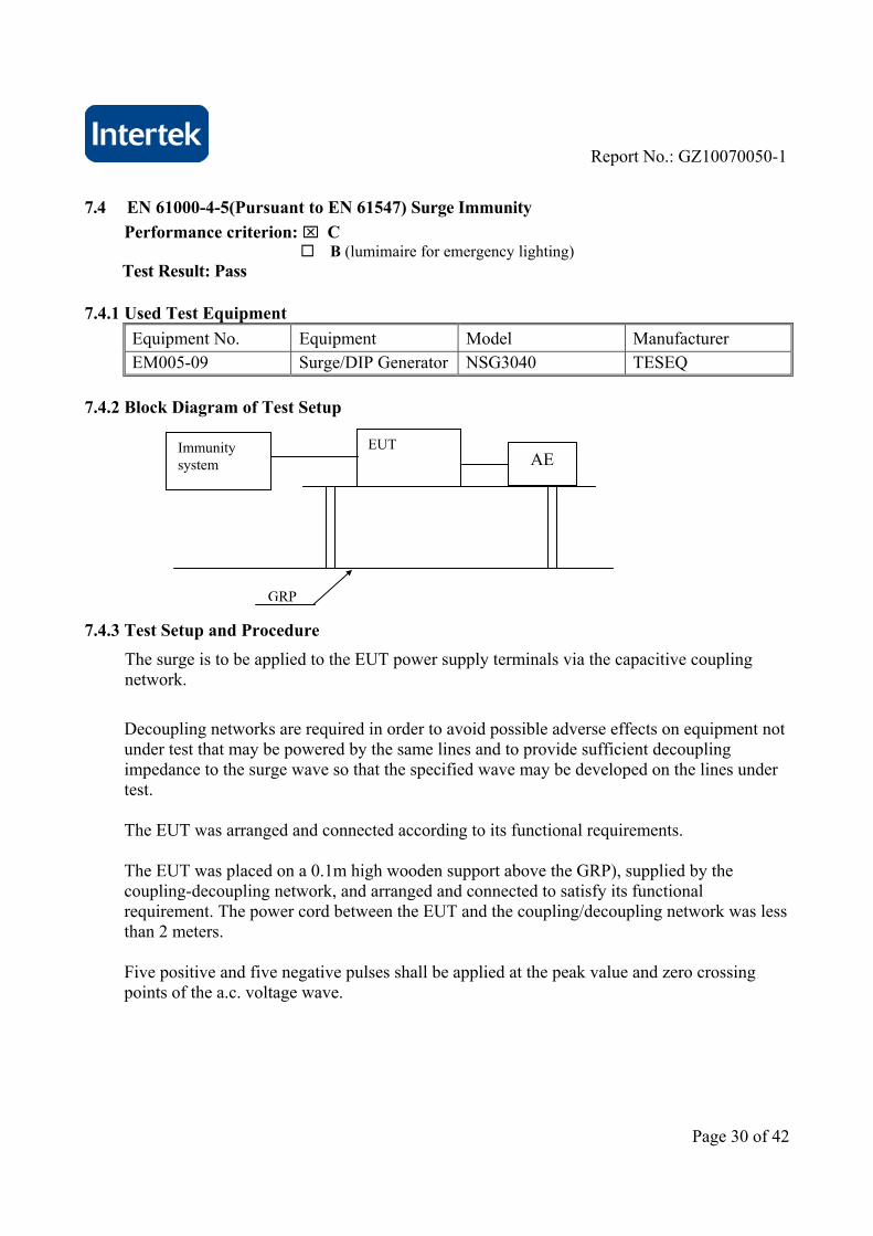
7.4 EN 61000-4-5(Pursuant to EN 61547) Surge Immunity
Performance criterion: C B (lumimaire for emergency lighting)
Test Result: Pass 7.4.1 Used Test Equipment
Equipment No. Equipment Model Manufacturer EM005-09 Surge/DIP Generator NSG3040 TESEQ
7.4.2 Block Diagram of Test Setup 7.4.3 Test Setup and Procedure
The surge is to be applied to the EUT power supply terminals via the capacitive coupling network.
Decoupling networks are required in order to avoid possible adverse effects on equipment not under test that may be powered by the same lines and to provide sufficient decoupling impedance to the surge wave so that the specified wave may be developed on the lines under test. The EUT was arranged and connected according to its functional requirements. The EUT was placed on a 0.1m high wooden support above the GRP), supplied by the coupling-decoupling network, and arranged and connected to satisfy its functional requirement. The power cord between the EUT and the coupling/decoupling network was less than 2 meters. Five positive and five negative pulses shall be applied at the peak value and zero crossing points of the a.c. voltage wave.
Immunity system
EUT
GRP
AE
Report No.: GZ10070050-1
Page 31 of 42
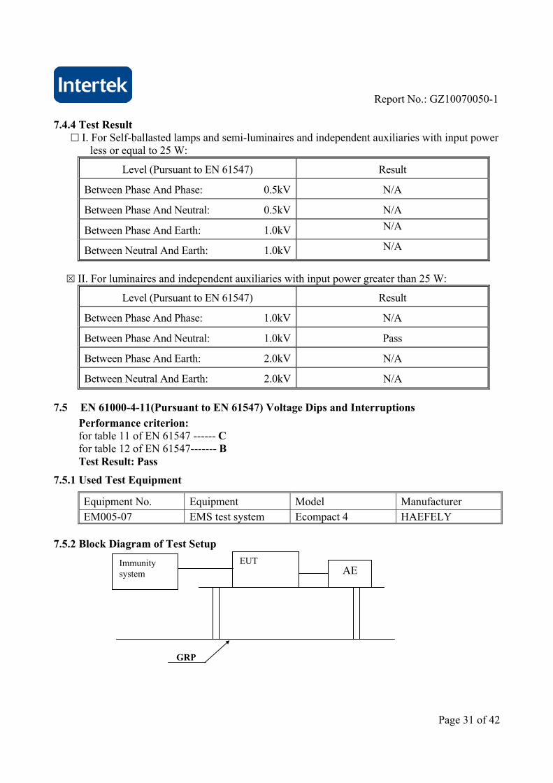
7.4.4 Test Result
I. For Self-ballasted lamps and semi-luminaires and independent auxiliaries with input power less or equal to 25 W:
Level (Pursuant to EN 61547) Result
Between Phase And Phase: 0.5kV N/A
Between Phase And Neutral: 0.5kV N/A
Between Phase And Earth: 1.0kV N/A
Between Neutral And Earth: 1.0kV N/A
II. For luminaires and independent auxiliaries with input power greater than 25 W:
Level (Pursuant to EN 61547) Result
Between Phase And Phase: 1.0kV N/A
Between Phase And Neutral: 1.0kV Pass
Between Phase And Earth: 2.0kV N/A
Between Neutral And Earth: 2.0kV N/A
7.5 EN 61000-4-11(Pursuant to EN 61547) Voltage Dips and Interruptions
Performance criterion: for table 11 of EN 61547 ------ C for table 12 of EN 61547------- B Test Result: Pass
7.5.1 Used Test Equipment
Equipment No. Equipment Model Manufacturer EM005-07 EMS test system Ecompact 4 HAEFELY
7.5.2 Block Diagram of Test Setup
Immunity system
EUT
GRP
AE

Report No.: GZ10070050-1
Page 32 of 42
7.5.3 Test Setup and Procedure The EUT was placed on an insulating support of 0.8m height, standing on a ground reference plane, and arranged and connected to satisfy its functional requirement The test was performed with the EUT connected to the test generator with the shortest power supply cable as specified by the EUT manufacturer. The EUT was tested for each selected combination of test level and duration with a sequence of three dips/interruptions with intervals of 10 s minimum. Each representative mode of operation was tested. EUT is tested for voltage reduction of 100%Ut, 0.5 period, 30%Ut, 10 periods,both the positive and negative polarity test was conducted. Abrupt changes in supply voltage was occur at zero crossings of the voltage and at additional angles considered critical by product committees or individual product specifications preferably selected from 45, 90, 135, 180, 225, 270, 315.
7.5.4 Test Result
I. According to table 11 of EN 61547
Test condition (Pursuant to EN 61547) Result
Test Level in %UT Duration (in period of the rated frequency)
70 10 Pass
II. According to table 12 of EN 61547
Test condition (Pursuant to EN 61547) Result
Test Level in %UT Duration (in period of the rated frequency)
0 0.5 Pass
Remark: UT is the rated voltage for the equipment.

Report No.: GZ10070050-1
Page 33 of 42
7.6 EN 61000-4-3(Pursuant to EN 61547) Radiated Electromagnetic Field Immunity
Performance criterion: A Test Result: Pass
7.6.1 Used Test Equipment
Equipment No. Equipment Model Manufacturer SZ061-04 BiConiLog Antenna 3142C ETS SZ180-01 Signal Generator SML03 R&S SZ181-01 Amplifier AP32 MT215 PRANA SZ181-02 Power Amplifier AS0825-35 MILMEGA SZ182-01 RF Power Meter 4232A BOONTON SZ186-01 Field Probe HI-6105 ETS SZ188-02 Anechoic Chamber RFD-F/A-100 ETS
7.6.2 Block Diagram of Test Setup
Power
Antenna mask
Table
amplifier Signal
EUT
Field probe
Field
Optical
Filter

Report No.: GZ10070050-1
Page 34 of 42
7.6.3 Test Setup and Procedure
The test was conducted in an fully anechoic chamber to maintain a uniform field of sufficient dimensions with respect to the EUT, and also in order to comply with various national and international laws prohibiting interference to radio communications.
The equipment is placed in the test facility on a non-conducting table 0.8m high (for floor standing EUT, is placed on a non-conducting support 0.1m height).
The EUT was placed on the uniform calibrated plane which is 3V/m EM field.
For all ports connected to EUT, manufacturer specified cable type and length was used, for those cables no specification, unshielded cable applied.
Wire is left exposed to the electromagnetic field for a distance of 1m from the EUT.
The EUT was arranged and connected according to its functional requirements
Before testing, the intensity of the established field strength have been checked by placing the field sensor at a calibration grid point, and with the field generating antenna and cables in the same positions as used for the calibration, the forward power needed to give the calibrated field strength was measured.
Spot checks was made at a number of calibration grid points over the frequency range 80MHz to 1000MHz, both polarizations was checked.
After calibration, the EUT is initially placed with one face coincident with the calibration plane.
The frequency range is swept from 80MHz to 1000MHz, with the signal 80% amplitude modulated with a 1 kHz sinewave, pausing to adjust the r.f. signal level.
The dwell time at each frequency was 3s so as that the EUT to be exercised and be able to respond.
The step size was 1% of the fundamental with linear interpolation between calibrated points. Test was performed with the generating antenna facing each of the four sides of the EUT.
7.6.4 Test Result
Frequency (MHz)
Exposed Side Field Strength (V/m)
Result
80 to 1000 Front 3V/m (r.m.s.) Pass
80 to 1000 Left 3V/m (r.m.s.) Pass
80 to 1000 Rear 3V/m (r.m.s.) Pass
80 to 1000 Right 3V/m (r.m.s.) Pass

Report No.: GZ10070050-1
Page 35 of 42
7.7 EN 61000-4-8(Pursuant to EN 61547) Power Frequency Magnetic Field Immunity
Performance criterion: A
Test Result: Not Applicable Remark: Equipment containing no Hall elements or magnetic field sensors is not susceptible to magnetic field.Hence, this equipment is deemed to fulfil the magnetic field test.

Report No.: GZ10070050-1
Page 36 of 42
8 Appendix I - Photos of test setup
Conducted Emission
ESD Immunity

Report No.: GZ10070050-1
Page 37 of 42
Conducted Immunity
EFT, Dips Immunity
Report No.: GZ10070050-1
Page 38 of 42
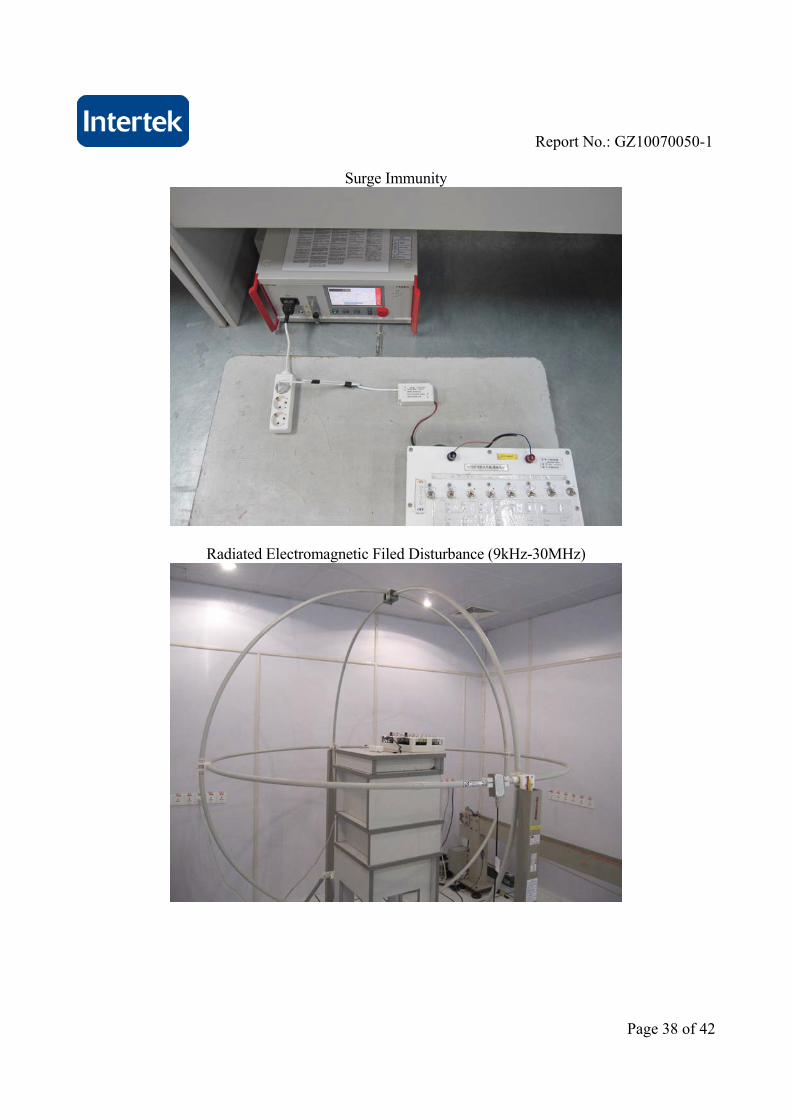
Surge Immunity
Radiated Electromagnetic Filed Disturbance (9kHz-30MHz)

Report No.: GZ10070050-1
Page 39 of 42
Radiated Electromagnetic Filed Disturbance (30MHz-300MHz)