report on accident to alliance air boeing 737 · pdf filereport on accident to alliance air...
TRANSCRIPT
REPORT ON
ACCIDENT TO ALLIANCE AIR BOEING 737-200 AIRCRAFT VT-EGD ON 17TH JULY, 2000
AT PATNA
BY THE COURT OF INQUIRY
AIR MARSHAL P. RAJ KUMAR, PVSM, AVSM, VM PROGRAMME DIRECTOR (FLIGHT TEST)
AERONAUTICAL DEVELOPMENT AGENCY, BANGLORE GOVERNMENT OF INDIA
MINISTRY OF CIVIL AVIATION
GOVERNMENT OF INDIA
MINISTRY OF CIVIL AVIATION

REPORT
ON ACCIDENT TO ALLIANCE AIR BOEING 737-200
AIRCRAFT VT-EGD ON 17TH JULY, 2000 AT PATNA
BY THE COURT OF INQUIRY
AIR MARSHAL P. RAJ KUMAR, PVSM, AVSM, VM PROGRAMME DIRECTOR (FLIGHT TEST)
AERONAUTICAL DEVELOPMENT AGENCY, BANGLORE
ASSESSORS 1. CAPT. N.S. MEHTA, DIRECTOR, AIR SAFETY (Retd.) AIR-INDIA LTD. 2. SHRI SHAILESH A. DESHMUKH, GENERAL MANAGER-ENGG. (QC&TS) AIR-INDIA LTD. SECRETARY SHRI S.N. DWIVEDI DY. DIRECTOR OF AIRWORTHINESS, D.G.C.A.
NEW DELHI 31ST MARCH, 2001

CONTENTS
CHAPTER NO. SUBJECT PAGE NO.
Executive Summary 1
Glossary of Terms 2
1 Factual Information 3
1.1 History of the Flight 10
1.2 Injuries to Persons 14
1.3 Damage to Aircraft 15
1.4 Other Damage 15
1.5 Personal Information 15
1.6 Aircraft Information 17
1.7 Meteorological Information 35
1.8 Aids to Navigation 36
1.9 Communications 38
1.10 Aerodrome Information 38
1.11 Flight Recorders 40
1.12 Wreckage and Impact Information 41
1.13 Medical and Pathological Information 51

1.14 Fire 52
1.15 Survival Aspects 55
1.16 Tests and Research 56
1.17 Organizational and Management 60
Information
1.18 Initial Actions 63
2 Analysis 65
2.1 Airworthiness Aspects 65
2.2 Weather 70
2.3 Sabotage Aspects 71
2.4 Analysis of Flight Recorders 76
2.5 Circumstances Leading to the 88 accident of the aircraft
2.6 Pilot Factor 99
2.7 Organizational Aspects 104
2.8 Analysis of Infrastructure at 109
Patna Airport
3 Conclusions 119
3.1 Findings 119
3.2 Cause of the Accident 121
4 Recommendations 122
Acknowledgements 125

LIST OF ANNEXURES
“A” WRECKAGE DIAGRAM OF ALLIANCE AIR CRASH “B-1”-“B-17” SEVENTEEN PHOTOGRAPHS OF ACCIDENT SITE “C” CVR TAPE TRANSCRIPT “D-1”-“D-3” FDR DATA PLOTS, LAST 40 SECONDS WITH CVR,
TAKE OFF AT KOLKATA & HEADING PLOT FOR THE LAST 06 MINUTES OF FLIGHT
“E-1”-“E-2” PATNA APPROACH CHARTS. 13 DME ARC APPROACH
& MISSED APPROACH PROCEDURES FOR RUNWAY 25
“F” NOTIFICATION OF MINISTRY OF CIVIL AVIATION
APPOINTING COURT OF INQUIRY “G” LIST OF WITNESSES EXAMINED DURING PUBLIC
HEARING “H” ESTIMATED FDR GROUND TRACK-CVR CORRELATION “I” HYDRAULIC SCHEMATIC DIAGRAM OF LEADING EDGE
DEVICES OF B-737 “J” FLIGHT CONTROL PANEL ON COCKPIT FORWARD
OVERHEAD PANEL OF B-737 “K” DIAGRAM SHOWING OPERATION OF FLAP LEVER “L” DIAGRAM SHOWING INDICATION PANEL OF LE
DEVICES “M” EXTRACT OF OPERATIONS MANUAL OF B-737-
“APPROACH TO STALL RECOVERY” PROCEDURE

1
EXECUTIVE SUMMARY
On 17th July, 2000, Alliance Air flight CD-7412, a Boeing 737-200 ADV aircraft VT-EGD crashed at 0734 hrs. (IST) while on approach to Patna airport. The flight had taken off from Kolkata at 0650 hrs. and was on a scheduled flight to Delhi via Patna and Lucknow. Two Pilots, four Air-hostesses and 52 passengers were on board. Patna weather was clear with a visibility of four kilometers. Approximately, 30 seconds prior to the crash, the crew requested a 360º turn due to being high on approach and were cleared by the Air Traffic Controller on duty. The aircraft stalled shortly after commencing the 360º turn and crashed in the Gardani Bagh residential area. All the crew and 49 passengers were killed as a result of the crash. The aircraft was completely destroyed by the crash and post crash fire. Five persons on the ground lost their lives. The Court of Inquiry determined that the cause of the accident was loss of control of the aircraft due to human error (air crew). The crew had not followed the correct approach procedure which resulted in the aircraft being high on approach. They had kept the engines at idle thrust and allowed the air speed to reduce to a lower than normally permissible value on approach. They then maneuvered the aircraft with high pitch attitude and executed rapid roll reversals. This resulted in actuation of the stick shaker stall warning indicating an approaching stall. At this stage, the crew initiated a Go Around procedure instead of Approach to Stall Recovery procedure resulting in an actual stall of the aircraft, loss of control and subsequent impact with the ground. The Court of Inquiry also determined that the aircraft was fully airworthy and was properly maintained. No in-flight failure of any system had occurred. In the course of the investigations, the Court observed that Patna airport had several operational constraints resulting in erosion of safety margins for operation of Airbus 320/Boeing 737 type of aircraft. In addition, Patna airport had no further scope for expansion. The Court has recommended the following :-
(a) Improvements in crew training procedures and re-organisation of the quality control set up of Alliance Air.
(b) Removal of constraints for operation of A-320/B-737 aircraft at Patna airport.
(c) Development of Air Force station Bihta as an alternative to the existing Patna airport.
(d) The Airports Authority of India (AAI) should maintain landing and navigational aids and airport equipment at all airports in the country to the required standards.

2
GLOSSARY OF TERMS
ACTUATOR :- A device that transforms hydraulic fluid
pressure into mechanical force, which is then used to operate
control surfaces of the a/c or other components such as landing
gears.
AILERON : - A control surface mounted on the rear
(Trailing edge) of each wing, moving in opposite directions
controls the lateral axis of the a/c.
KINEMATICS: - A process that involves fitting curves through
available Flight Data Recorder (FDR) data (Heading, Pitch,
Roll), obtaining flight control time history rates from these
curves and obtaining accelerations from these rates. Forces,
Moments and Aerodynamic Coefficients are then obtained from
those accelerations using Newton’s Laws.
LANDING REFERENCE SPEED, VREF: - The minimum speed
at the 50-feet height in a normal landing. This speed must be at
least 1.23 times the 1g stall speed in the landing configuration.
OAT : - Outside Air Temperature – the free air static (ambient)
temperature.

3
REPORT ON THE ACCIDENT INVOLVING
ALLIANCE AIR BOEING 737-200 AIRCRAFT
VT-EGD AT PATNA ON 17TH JULY, 2000
(a) Aircraft Engines
Type : Boeing 737 Maker : Pratt & Whitney
Model : 200 Type : JT8D-17A
Nationality : Indian Left : S/N ESN-P-674152B
Registration : VT-EGD Right : S/N ESN-P-709360B
(b) Owner : Indian Airlines Ltd. Airlines House, New Delhi (c) Operator : Airlines Allied Services Ltd. (Alliance Air), IGI Airport, New Delhi (d) Pilot-In-Command : Capt. M.S. Sohanpal
Extent of Injuries : Fatal
(e) Co-Pilot : Capt. A.S. Bagga
Extent of Injuries : Fatal
(f) No. of Cabin Crew : Four
Extent of Injuries : Fatal
(g) No. of Passengers : 52
Extent of Injuries : Fatal - 45
Injured - 6
Unhurt - 1
(Four of the injured passengers

4
succumbed later) (h) Place of Accident: Gardani Bagh Near
Patna Airport
1 Km Left of Approach Path to R/W 25
and 1 km short of the runway threshold
Latitude - 17º35’24” North
Longitude - 085º06’18” North
(I) Date And Time of : 17TH July, 2000
Accident at 0734 hrs.
(All timings in the report are in IST)
SUMMARY
Alliance Air Flight No. CD-7412 departed Netaji Subhash
Chandra Bose International Airport, Kolkata at 0651 hrs. on 17th
July, 2000 bound for Patna-Lucknow-Delhi. After normal
departure from Runway 01R, the aircraft climbed to FL 260 on
track to Patna via route W52. The aircraft was under the
control of Kolkata Radar from 0652 hrs. to 0659 hrs. It changed
over to Kolkata Area Control Centre. The aircraft reported
position SAREK at FL 260 at 0712 hrs. and changed over to
Patna Control with information that there was no reported traffic
for descent. The aircraft contacted Patna ATC at 0713 hrs. and
gave it’s ETA at Patna as 0736 hrs.

5
Patna ATC cleared the aircraft to PPT VOR ILS/DME
ARC Approach for R/W 25. The ATC Officer communicated
that Patna METAR originated at 0650 hrs. stated “Wind calm,
Visibility 4000 metres, Weather Haze, Clouds Broken 25000
feet, temp 29ºC, Dew Point 27º, QNH 996 hPa, No Sig”.
The aircraft was cleared to descend to 7500’ and report 25
DME from PPT VOR. The aircraft reported 25 DME at 0726
hrs. The aircraft then descended to 4000’ on QNH 996 hPa
and was asked to report 13 DME for ILS/DME ARC Approach
R/W 25. The aircraft reported commencing the ARC at 0728
hrs. The aircraft reported crossing lead radial 080 at 0731 hrs.
and coming on to the Localizer. The aircraft was then asked to
descend to 1700’ on QNH 997 hPa with instructions to call
established on Localizer. The aircraft informed Patna ATC at
0732 hrs. that it would like to do a 360º turn due to being high
on approach. Patna ATC sought confirmation from the aircraft
whether it had the airfield in sight and on receiving an
affirmative reply, asked the aircraft to report on finals for R/W
25 after carrying out a 360º turn. This was acknowledged by
the aircraft at 0732 hrs. This was the last communication from
the aircraft. Immediately thereafter, the aircraft was spotted by
the Air Traffic Controller in normal descent aligned with the R/W
25. It, however, appeared to be high on approach. The aircraft
then turned steeply to the left losing height all of a sudden and
disappeared from sight behind a row of trees. The Air Traffic
Controller observed a huge column of smoke rising from the

6
Gardani Bagh area outside the airfield perimeter and initiated
crash action.
INITIATION OF INVESTIGATION :
On receiving information about the accident, Shri H.S.
Khola, Director General of Civil Aviation along with S/Shri K.
Gohain, Dy. Director General of Civil Aviation, N. Ramesh, Dy.
Director General of Civil Aviation, S.S. Nat, Director of
Airworthiness, Delhi Region, V.K. Chandna, Director of Air
Safety proceeded to the accident site on 17th July, 2000.
Investigation was started immediately in coordination with
officials of Airports Authority of India, police, Indian Airlines and
Alliance Air. Chairman & Managing Director, Indian Airlines,
Secretary, Ministry of Civil Aviation along with Honorable
Minister of Civil Aviation also visited the accident site on the
same day. Shri P. Shaw, Regional Controller of Air Safety,
Kolkata also visited the accident site on 17th July, 2000 and
started the accident investigation. Shri P. Shaw, Regional
Controller of Air Safety, Kolkata was appointed as Inspector of
Accidents, under Rule 71 of Aircraft Rules, 1937 to investigate
the accident by the Director General of Civil Aviation on 17th
July, 2000.
Subsequently, the Govt. of India, Ministry of Civil Aviation
appointed a Court of Inquiry under Rule 75 of the Aircraft Rules,
1937 vide Notification No. AV.15013/2/2000-SS dated 8th

7
August, 2000 to investigate the accident. The Court of Inquiry
was headed by Air Marshal P. Rajkumar, Programme Director
(Flight Test), Aeronautical Development Agency, Bangalore.
Shri Shailesh A. Deshmukh, General Manager-Engineering
(QC&TS), Air-India and Captain N.S. Mehta, Director-Air Safety
(Retd.) & Senior Boeing 747-400 Commander, Air-India were
appointed as Assessors to the Court. Shri S.N. Dwivedi, Dy.
Director of Airworthiness, DGCA was appointed as Secretary to
the Court. The Headquarters of the Court of Inquiry was Delhi.
The Court of Inquiry, soon after its appointment, held an
initial sitting at Delhi on 10th August, 2000 to decide the course
of action in order to carry out the investigation of the accident.
Thereafter, the Court of Inquiry along with the Assessors and
the Secretary visited the accident site at Patna on 11th and 12th
August, 2000. During this visit, the Court of Inquiry visited the
accident site to assess the circumstances of the accident and
ascertain the damage caused to civilian property. The Court of
Inquiry carried out examination of the wreckage at the accident
site and examined key witnesses. The Court of Inquiry met
important Bihar State Government functionaries like the Chief
Secretary, Director General of Police, District Magistrate, Patna
and the Chief Justice of the Patna High Court.
The Chief Justice of the Patna High Court Mr. Justice
Ravi Dhawan informed the Court that he had not acceded to
the request made by the Ministry of Civil Aviation, Govt. of India

8
to provide a sitting Judge of the Patna High Court to carry out
the inquiry. He said that he was convinced that it was a matter
to be investigated by a technically competent person. All efforts
made by the Ministry of Civil Aviation to convince the Chief
Justice to provide a sitting Judge were in vain and resulted in
the constitution of the Court of Inquiry only on 8th August, 2000,
three weeks after the accident.
Notification regarding constitution of the Court of Inquiry
was published in leading daily newspapers at Delhi, Lucknow,
Patna and Kolkata between 18th and 21st August, 2000. The
general public was invited to come forward to provide details of
the accident, which may be of material use to the conduct of the
inquiry.
The Court of Inquiry visited Kolkata Airport on 24th
August, 2000 to examine Engineering and Flight Dispatch
personnel of Indian Airlines Ltd., since, they had dispatched the
aircraft and were the last to see the passengers and crew on
the morning of 17th July, 2000. The maintenance facilities of
Indian Airlines Ltd. at Kolkata were inspected. The Air Traffic
Controllers of AAI who performed the duties of Air Traffic
Control at Kolkata on 17th July, 2000, were also examined.
The Court of Inquiry held public hearings at Patna from 4 th
to 6th September, 2000. A total of 41 witnesses were examined
during the public hearings. The witnesses who gave their

9
testimony at the public hearing included members of the public,
who had witnessed the last few moments of the flight before its
crash and those who had participated in the rescue operation.
Patna Airport Fire Service personnel, the City Fire Brigade
officials, Police officials and Doctors of the Patna Medical
College Hospital also gave their testimony during the hearing.
On 11th September, 2000, the Court assembled at Delhi
and released the information regarding material facts relating to
accident on a web site with the address
“http://civilaviation.nic.in/coi”
Thereafter, the court reconvened at Mumbai on 15th
September, 2000 to examine the Pratt & Whitney JT8D-17A
engines of B737-200 aircraft VT-EGD, which were recovered
from the wreckage at the crash site at Patna and transported to
the Engine Overhaul Facility of, Air-India, Mumbai.
The Court of Inquiry held public hearings at Delhi from
18th to 21st September, 2000. It examined a total of 30
witnesses belonging to various organisations e.g. Indian
Airlines, Alliance Air, Airports Authority of India, DGCA and Air-
India.
The Court of Inquiry along with its members visited Patna
Medical College Hospital (PMCH) on 27th September, 2000 to
examine the facilities available there. Since, all the injured

10
passengers as well as passengers and crew members with
fatal injuries were moved to PMCH on 17th July, 2000 after the
accident, the Court decided to obtain a first hand knowledge
about the availability of various facilities at PMCH.
The Court along with its members also visited Air Force
Station, Bihta, Patna on 28th September, 2000 to assess the
suitability of that airfield for the operation of scheduled civil
flights.
1. FACTUAL INFORMATION
1.1 History Of The Flight
On 17th July 2000, the operating crew reported for
flight briefing at the Alliance Air Operations, Kolkata at
0545 hrs. The scheduled Time of Departure (STD)
Kolkata of CD-7412 was 0630 hrs.
All six crew members, two pilots and four cabin
crew underwent pre-flight medical examination including
breath analyser test and were found fit.
The pilots were briefed about the weather at
destination, alternate and at Kolkata. The pilots were also
briefed about Patna ILS Glide Slope being restricted to
300 feet as per the communication NOTAM. The flight
11
plan fuel was 7.4 tonnes. The pilot in command, however,
requested for 600kgs. extra fuel. Hence the total fuel on
board was 8 tonnes (8000kgs.) at Kolkata. The trip fuel
for the Kolkata-Patna leg was estimated at 2.5 tonnes.
The load and trim sheet data indicated aircraft take-
off weight of 42714kgs., estimated landing weight of
40130kgs. and balance index of 21 & 20 respectively.
The aircraft VT-EGD had arrived at Kolkata on 15th
July 2000, at 2200 hrs. There were no reported defects
on this flight. The aircraft underwent a ‘Layover Check’.
There were no observed defects except for one
windshield wiper, which was replaced. 16th July was a
Sunday and Alliance Air schedule reportedly did not need
this aircraft. The aircraft remained on ground at Kolkata
throughout the Sunday.
On 17th July, the aircraft was prepared for flight CD-
7412, Kolkata – Patna – Lucknow – Delhi. The aircraft
was positioned on Bay No. 33 and the pilots had reported
a total of 58 persons on board through security. Recorded
VHF R/T conversation between Kolkata ATC and the
aircraft records that the flight was cleared for pushback
and start up at 0640 hrs. Kolkata ATC cleared the flight to
Patna via route W52 FL 260 (Flight Level 26000 ft) with
instructions that after departure from R/W 01R the aircraft

12
had to climb straight ahead to 4000 ft., turn left and then
climb on track. The aircraft was airborne at 06.51 hrs. and
thereafter it changed over to Kolkata Radar.
The aircraft was with Kolkata Radar from 0652 hrs.
till 0659 hrs. and then changed over to Kolkata Area
Control. At 0712 hrs., the aircraft reported position
SAREK FL 260 and it changed over to Patna after being
informed by Kolkata Area Control that there was no
reported traffic for descent. However, the pilot, reported
that he could not read the message and it was once again
read back by the Area Controller but he still reported that
the transmission was unreadable and changed over to
Patna ATC.
VHF R/T conversation between the pilots and Patna
ATC confirmed that at 07:13:35 hrs., the aircraft had
called Patna ATC while maintaining FL 260 and
communicated ETA Patna as 0736 hrs. The pilot also
informed Patna ATC that the aircraft had crossed SAREK
at 07:11 hrs. Patna ATC cleared the aircraft to
PPT(VOR) ILS DME ARC approach runway 25,
Transition level FL 55. The ATC Officer also
communicated Patna Metar of 0120 UTC (0650 IST) –
“wind calm, visibility 4000 meters, weather haze, cloud
broken 25000 ft., temperature 29, dew point 27, QNH-
996, hPa No sig.”

13
Patna ATC asked the aircraft at 0717 hrs. to report
for descent and also to check descent traffic with Kolkata
Area Control. The aircraft soon responded that Kolkata
had reported negative traffic. The aircraft was then
cleared for descent to FL 75 and asked to report 25 NM
and the same was reported by the aircraft at 07:26:09
hrs.. The aircraft was cleared to descend to 4000 ft. on
QNH 996 hPa and was asked to report 13 DME for ILS-
DME ARC approach runway 25. At 07:28:02 hrs., the
aircraft reported commencing the arc and at 07:31:26 hrs.
reported crossing the lead radial and coming up on the
localiser. The aircraft was then asked to descend to 1700
ft. on QNH 997 hPa with instructions to report established
on localiser. The aircraft acknowledged the transmission.
At 07:32:30 hrs., the aircraft informed Patna ATC that
they would like to do a 360 due high on approach. Patna
ATC sought confirmation from the aircraft about the
aerodrome being in sight, which was confirmed. The
aircraft was asked to report finals for R/W 25 after
carrying out a 360 and the clearance was acknowledged
by the pilot at 07:32:40 hrs. This was the last
transmission available on the Patna ATC tape.
As per the ATC officer, Patna after giving
permission to carry out a 360o orbit, he started looking
out for the aircraft and could see it before Patna

14
Secretariat Tower, which is approx. 2 Kms. from the
threshold of runway 25. At that time, he noticed that the
aircraft was on a normal flight path and aligned with the
runway center line. It was however high on the approach.
Thereafter, he noticed the aircraft turning left after
crossing the Secretariat Tower i.e. towards southeast of
the aerodrome and losing height all of a sudden. The
aircraft went out of sight behind trees. He made several
calls to the aircraft but there was no reply from the
aircraft. The ATC tape had nine calls to the aircraft made
by the ATCO from 07:34:00 to 07:34:48 hrs. As per the
ATC tape, there was no emergency call from the aircraft
while losing height.
No sign of fire was observed by the ATC Officer as
long as the aircraft was in view. The ATC Officer
presuming that the aircraft had crashed switched on/off
the crash siren and fire bell. At the same time, he
observed a huge column of smoke from the Gardanibagh
area just to the left of the threshold of runway 25.
1.2 Injuries to Persons after the crash.
INJURIES FATAL SERIOUS MINOR
Crew 2+4 - -
Passengers 49 2 1
Others 5 5 -

15
1.3 Damage to the Aircraft
The aircraft was totally destroyed on impact with the
ground and post impact fire.
1.4 Other Damage
Two Residential quarters No. 6&8 on Gardani Bagh,
Road No. 29 were destroyed and another residential
quarter No. 9 on the same road sustained damage to its
roof.
1.5 Personnel Information
1.5.1 Pilot in Command - Capt. M.S.Sohanpal
Date Of Birth 2nd May, 1965
ALTP No 2089, valid till 17th Nov. 2000
FRTO Number 3581 valid till 14th Sept. 2000
RTR No. 5890 valid till 22nd March, 2002
Date of Last Medical Examination
03.05.2000 (Assessment-FIT)
Instrument Rating & Licence Renewal Check
25-05-2000 Above standard
Date of Last Route Check 01.05.2000 (Proficiency A.S.)
Date of Last Refresher 02.03.2000 (Result Pass)

16
Date of Endorsement on B-737-200
P1: 06.02.1998 P2: 29.10.1992
Experience on B-737-200 aircraft (as on 15.7.2000)
P1:1778:15 hrs
Total Flying Experience (as on 15.7.2000)
4361:15 hrs
Hrs. flown in the last 365 days 602:00
Hrs. flown in the last 90 days 132:25
Hrs. flown in the last 30 days 68:00
Hrs. flown; in the last 7 days 12:15
Hrs. flown in the last 24 hrs. 05:20
Rest availed prior to the flight 15:20 hrs.
1.5.2 First Officer - Capt. A.S.Bagga.
Date Of Birth 11th November, 1968
ALTP No 2057, valid till 26th June, 2001
FRTO Number 3828 valid till 7th May, 2001
RTR No. 6144 valid till 21st Sept., 2002
Date of Last Medical Examination
07.03.2000 (Assessment-FIT)
Instrument Rating & Licence Renewal Check
23.3.2000 Above standard
Date of Last Route Check 23.03.2000 (Proficiency A.S.)
Date of Last Refresher 02.09.1999 (Result Pass)
Date of Endorsement on B737-200 (Not yet released as P1)
P1: 27.06.2000 P2: 01.04.1992

17
Experience on B-737-200 aircraft (as on 15.7.2000)
P2:3605 hrs
Total Flying Experience
(as on 15.7.2000)
4085 hrs
Hrs. flown in the last 365 days 612:00
Hrs. flown in the last 90 days 175:25
Hrs. flown in the last 30 days 77:00
Hrs. flown; in the last 7 days 15:55
Hrs. flown in the last 24 hrs. 02:30
Rest availed prior to the flight 19:40 hrs.
1.5.3 Cabin Crew
Ms. Sapna Anand, Ms. Pushpa Inder, Ms. Priyanky
Newar and Ms. Shweta Khurana.
1.6 Aircraft Information
Boeing 737-200 is a twin engine jet transport
airplane manufactured by Boeing Commercial Airplane
Company, USA. It is designed to operate over short to
medium ranges at cruise speeds of approximately 950
Kilometers/hour (Kmph). Two P&W JT8D/17A engines
power the aircraft, each developing approximately 16,000
Pounds (lbs) of thrust at sea level.

18
Typical seating capacity of this aircraft is 125
passenger (FAA exit limit is 136) but for Alliance Air fleet
it is 119 passenger General dimensions of B-737-200 are
100 ft. 2 inch length, 93 feet wing span, 36 ft. 10 inch
height of vertical fin.
B737-200 aircraft is equipped with a conventional
tricycle type retractable landing gear system. Wheel-base
is 17’2” and the longitudinal dimension between nose and
main landing gear is 37’4”.
The aircraft is pressurised using engine air bleed
and can be alternately pressurised using the auxiliary
power unit bleed up to the altitude of 17000 ft. The ceiling
altitude is 35000 ft. with a normal operating differential
pressure of 7.8 + 0.1 PSI.
The aircraft primary controls operate hydraulically,
on the three separate hydraulic systems of the aircraft
1.6.1 AIRCRAFT PARTICULARS
Date of Manufacture June 19, 1980
Serial No. 22280
Date of first landing in India June 23, 1980
Certificate of Registration No. 2186
Date of Registration in India June 26, 1980

19
Owner Indian Airlines Ltd., New Delhi
Operator Airlines Allied Services Ltd. (Alliance Air), New Delhi.
Certificate of Airworthiness No. 1718
Date of First issue June 18, 1980
Valid till March 25, 2001
Maximum all up weight 52390 Kg.
1.6.2 MAINTENANCE ARRANGEMENTS
Alliance Air, subsidiary of Indian Airlines Ltd., is
approved by DGCA, to carry out maintenance of Boeing
737-200 aircraft, its systems and the P&W JT8D Engines
up to issue of Flight Release Certificate (3A Check).
Higher Inspection schedules are carried out by Indian
Airlines Ltd. at their facility at Delhi.
1.6.3 Airframe Particulars
Airframe Hrs. since New 44087:33 hrs.
Airframe Landings/ Cycles since new
51278 cycles
Hrs. since Last C of A Renewal Inspection
981.08 hrs.
Cycle since Last C of A Renewal Inspection
1177 cycles
Last Periodic “Layover” check completed on
17.07.00 morning
20
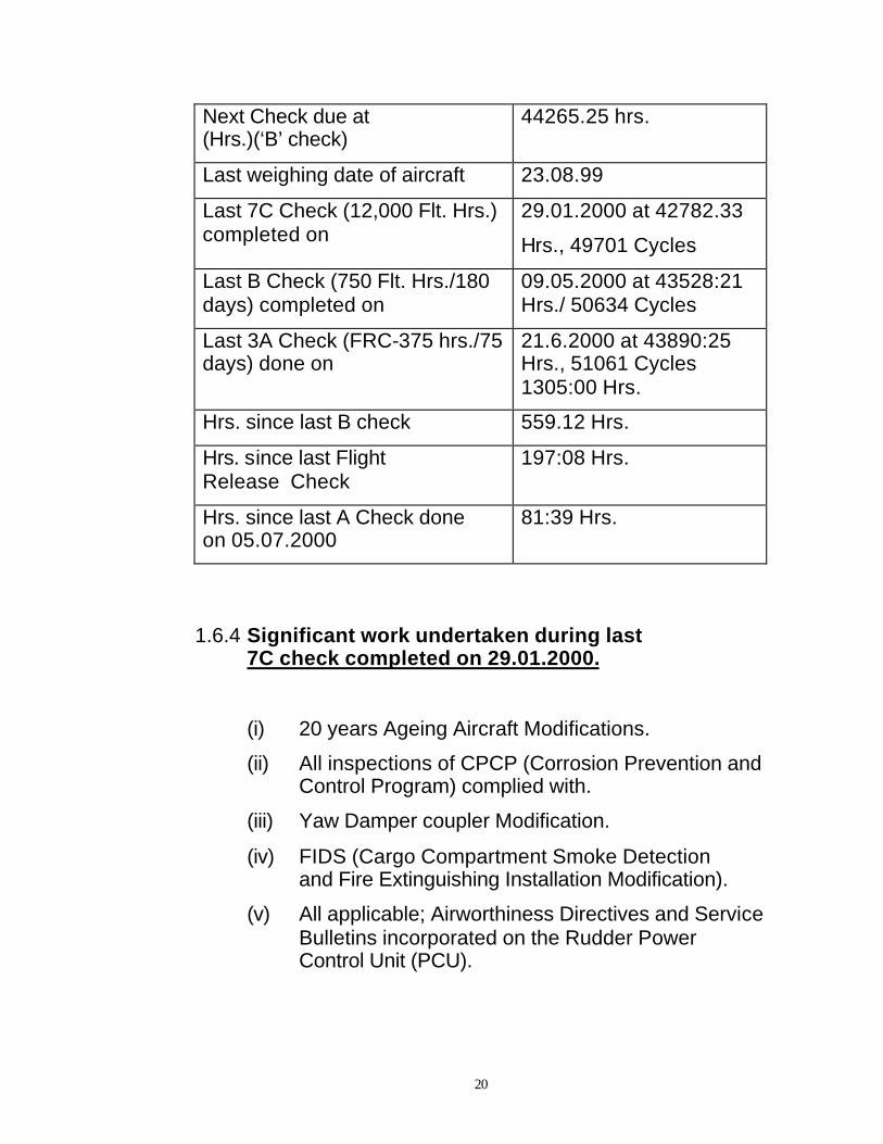
Next Check due at (Hrs.)(‘B’ check)
44265.25 hrs.
Last weighing date of aircraft 23.08.99
Last 7C Check (12,000 Flt. Hrs.) completed on
29.01.2000 at 42782.33
Hrs., 49701 Cycles
Last B Check (750 Flt. Hrs./180 days) completed on
09.05.2000 at 43528:21 Hrs./ 50634 Cycles
Last 3A Check (FRC-375 hrs./75 days) done on
21.6.2000 at 43890:25 Hrs., 51061 Cycles 1305:00 Hrs.
Hrs. since last B check 559.12 Hrs.
Hrs. since last Flight Release Check
197:08 Hrs.
Hrs. since last A Check done on 05.07.2000
81:39 Hrs.
1.6.4 Significant work undertaken during last 7C check completed on 29.01.2000.
(i) 20 years Ageing Aircraft Modifications.
(ii) All inspections of CPCP (Corrosion Prevention and Control Program) complied with.
(iii) Yaw Damper coupler Modification.
(iv) FIDS (Cargo Compartment Smoke Detection and Fire Extinguishing Installation Modification).
(v) All applicable; Airworthiness Directives and Service Bulletins incorporated on the Rudder Power Control Unit (PCU).

21
1.6.5 Engine Particulars: Left Hand (LH) & Right Hand (RH)
Engine manufacturer Pratt & Whitney
Engine type JT8D-17A
Engine Serial No. LH S/No. P674152B RH S/No. P709360B
Date of Installation on the aircraft
LH 29-01-2000 during 7C Check RH 29-01-2000 during 7C Check
Hrs. since Overhaul LH-12347:00 RH-8154:12
Cycles Since Overhaul LH – 13931 RH – 9387
Hrs. since New LH – 34289:00 RH – 29121:57
Cycles since New LH – 49679 RH – 34074
Last Heavy Maintenance Inspection (HM) on Port Engine completed on
28.04.1999
Time since HM 2462:27 Hrs./ 2835 Cycles
Last Hot Section Inspection (HIS) on Stbd. Engine completed on
18.06.1998
Time since HIS 4226:07 Hrs./4909 cycles
1.6.6 APU Particulars
APU Manufacturer (Allied Signal)
Garrett Turbine Engine Company
APU Type GTCP85 – 129

22
APU Serial Number P334990
Hrs. since New 56291.22
Hrs. since last Overhaul 6792:02
1.6.7 GROUND PROXIMITY WARNING SYSTEM (GPWS)
The aircraft was equipped with a Mode 5 GPWS
manufactured by Sundstrand Data Control. The system
provides the crew with aural and visual warnings of
potentially dangerous flight pattern in relation to terrain
being flown when one or more of flight thresholds are
exceeded.
WARNING
MODE REASON AURAL WARNING
Mode 1 Excessive descent rate
“WHOOP WHOOP PULL UP”
Mode 2 Excessive terrain closure rate
“WHOOP WHOOP PULL UP”
Mode 3 Altitude loss after take off or go-around
“WHOOP WHOOP PULL UP”
Mode 4 Unsafe terrain clearance when not in the landing mode
“WHOOP WHOOP PULL UP”
Mode 5 Below glide slope. Deviation alert.
“GLIDE SLOPE”

23
1.6.8 HYDRAULIC SYSTEM OF BOEING 737-200 AIRCRAFT
The ‘A’ Hydraulic System is powered by Engine
Driven Hydraulic Pumps mounted on each engine. Either
pump is capable of providing System Operating Pressure
of 3000 PSI with a delivery of 22g/minute (even with
engine running at idle speed). This flow capacity is more
than adequate to meet the simultaneous utilisation of
flight controls including flap retraction. The ‘B’ Hydraulic
system is powered by two Electric Motor Driven Hydraulic
Pumps.
The Boeing 737-200 aircraft incorporates three
functionally independent hydraulic systems, which
operate at approximately 3000 Pounds Per Square Inch
(PSI) pressure. The systems are designated as System
‘A’, System ‘B’ and the ‘Standby’ System. Each system
has it’s own independent reservoir and it’s own control
and delivery System. System ‘A’ and ‘B’ normally
provide the dual hydraulic power for all Flight Control.
Each system alone can take care of all Flight Control
requirements. Capacity of each of the four hydraulic
pumps of System ‘A’ and ‘B’ are such that one pump
alone can meet the full flight control authority
requirements of it’s respective system.

24
The ‘A’ hydraulic system is powered by two Engine
Driven Hydraulic Pumps, one mounted on each engine.
This system supplies hydraulic power to Flight Controls,
Landing Gear, Nose Gear steering, Alternate Brakes,
Inboard Flight Spoilers, Ground Spoilers and Engine
Thrust Reversers.
The ‘B’ hydraulic system is powered by two Electric
Motor Driven Pumps. This system provides Leading
Edge Flaps and slats, outboard flight spoilers and normal
brakes.
The ‘Standby’ hydraulic system is powered by one
electric motor driven pump. The system has no separate
control switch but gets activated by arming ‘Alternate
Flaps’ on selecting ‘STANDBY RUDDER ‘A’ or ‘B’ on the
overhead panel in the Cockpit. This system provides
hydraulic power to Rudder Control System and extension
of Leading Edge Flaps & Slats (Retraction is not possible
with this system) in the alternate mode and alternate
operation of both Engine Thrust Reversers.
In the normal operation, both hydraulic systems ‘A’
and ‘B’ are switched ‘ON’. The ‘ALTERNATE FLAP’ is
switched to ‘OFF’. The ailerons and elevators can be
operated manually without power.

25
1.6.9 FLIGHT CONTROL SYSTEM
(a) LATERAL CONTROL
Lateral Control of the aircraft was
achieved by operation of an Aileron and two Flight
Spoilers on each wing. These surfaces were
operated by the Pilot and Co-Pilot control wheels in
the cockpit. A cable system connected the control
wheels to an Aileron control quadrant. The
quadrant operated the Aileron Power Control Unit
(PCU) through a mechanical link.
In normal operation, both control wheels
operated the Aileron PCU through the left Aileron
Cable System. In case of jamming of the left Cable
System, lateral control was achieved by operating
the Flight Spoilers through the right Aileron Cable
System. Control Wheel Movement of more than 9
degrees to the Left or Right activated the transfer
mechanism. An Aileron spring cartridge provided
the mechanical input connection between the Co-
Pilot’s Aileron input and the Aileron PCU.
The Spoilers were either operated by the
Aileron Control System or by the speed brake Lever
in the Cockpit. These two inputs were summed

26
together through a Spoiler Mixer. This allowed
Spoilers to be used for augmentation of lateral
control even when being used as speed brakes
simultaneously. The Spoiler Mixer also acted as a
ratio changer which changed the output to the
Spoiler Mixer for a given magnitude of input from
the Aileron System. With the speed brakes raised
the lateral Control Output decreased.
The Ailerons were controlled by two
independent hydraulic power control units (PCUs),
one connected to System ‘A’ and the other
connected to System ‘B’. Either unit was capable of
providing the full range of lateral control. Aileron
trim was provided by a mechanical actuator
operated from the Cockpit Pedestal Aileron Trim
Knob. This actuator repositioned the Aileron
Centering Mechanism.
Two Flight Spoilers on each wing worked in
conjunction with the Ailerons. With the speed brake
lever in the ‘DOWN’ Detent, the Spoilers on the Up-
Aileron side would start lifting at 9+1º equivalent
control wheel movement. In the ‘FLIGHT’ Detent
position, the Spoilers became operational at all
control wheel movement. Of the two Flight Spoilers,
the outboard operated on System ‘B’ and the

27
inboard on System ‘A’. All the four operated
together as Speed Brakes in flight.
Two Ground Spoilers on each wing operated
as drag devices for operation on ground only.
These four surfaces were operated by System ‘A’
hydraulic pressure. A mechanical link connected to
the Right Main Landing Gear operated a bypass
valve to prevent in-flight operation of the Ground
Spoilers.
(b) LONGITUDINAL CONTROL
Aircraft control in the longitudinal axis (Fore
and aft) was provided by Elevators and the movable
horizontal stabilizer. The Elevators were powered
by two independent hydraulic PCUs. One PCU
operated on System ‘A’ and other on System ‘B’.
Either unit could provide full pitch control.
The Pilot’s control was achieved through the
Control Column through a dual Cable System and
torque tube connected to both Elevators. The
Pilot’s Feel was provided by the Elevator Feel
System, which provided a hydraulic force
proportional to air speed and stabilizer position.

28
In the absence of hydraulic pressure, the
elevators were operated directly by the Control
Column. Tabs were provided on the elevators to
assist in manual operation. Hydraulic actuators lock
the tab to the elevator when hydraulic pressure was
available. The absence of hydraulic pressure
unlocked the tab.
Movement of the horizontal stabilizer provided
longitudinal trim. The stabilizer was operated by a
dual load path ball screw. The ball screw could be
operated by three means; the main electric trim
motor, auto pilot trim motor or the manual trim,
which was operated by trim wheels on either side of
the cockpit pedestal. The manual trim wheels were
connected to the horizontal stabilizer by a Cable
System.
(c) DIRECTIONAL CONTROL
Directional Control (YAW) about the vertical
axis was provided by operation of a Rudder. The
Rudder was a tabless surface operated only
through a hydraulic PCU with no possibility of
manual reversion. The Rudder PCU operated the
Rudder through a dual load path linkage and was
powered by both Hydraulic Systems ‘A’ & ‘B’ with

29
the capability to operate on any one system. Each
system operated through it’s own Control Module
mounted on the PCU.
The Standby Hydraulic System operated the
Rudder through a Standby Rudder Actuator,
providing a back up source. The Standby Actuator
received power only when operation was selected
by the Flight Control Switch either ‘A’ or ‘B’ to the
STANDBY RUDDER position. On selecting the
Standby Rudder position, hydraulic pressure from
one of the Hydraulic Systems was cut off to the
Rudder PCU. This ensured that only two Hydraulic
Systems operated the Rudder PCU at any one time.
Yaw Damper System operated the Rudder
through Hydraulic System ‘B’. Its authority was
limited to 2º left & right and did not provide any feed
back to the Rudder Pedals. The feel and centering
mechanism provided artificial feel for the Pilot.
Rudder trim was operated through a mechanical
actuator operated by the rudder trim knob on the
pedestal.
The Airworthiness Directive (AD) 97-14-03
introduced a Rudder Pressure Reducer. The
Pressure Reducer was mounted only on System ‘A’
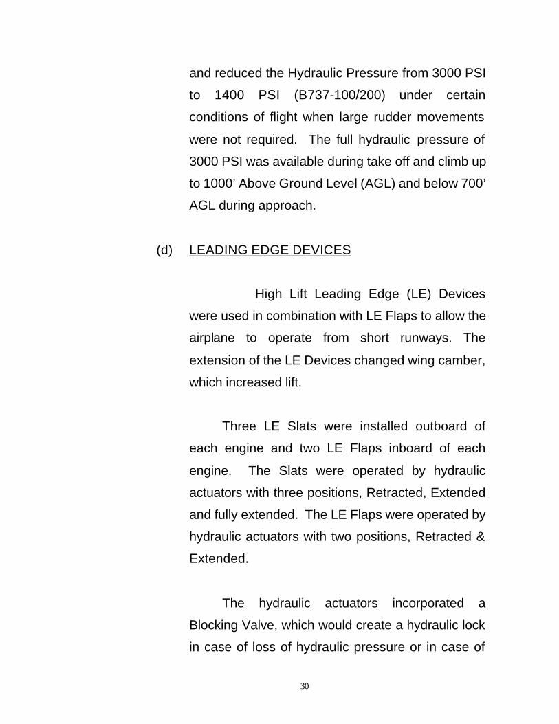
30
and reduced the Hydraulic Pressure from 3000 PSI
to 1400 PSI (B737-100/200) under certain
conditions of flight when large rudder movements
were not required. The full hydraulic pressure of
3000 PSI was available during take off and climb up
to 1000’ Above Ground Level (AGL) and below 700’
AGL during approach.
(d) LEADING EDGE DEVICES
High Lift Leading Edge (LE) Devices
were used in combination with LE Flaps to allow the
airplane to operate from short runways. The
extension of the LE Devices changed wing camber,
which increased lift.
Three LE Slats were installed outboard of
each engine and two LE Flaps inboard of each
engine. The Slats were operated by hydraulic
actuators with three positions, Retracted, Extended
and fully extended. The LE Flaps were operated by
hydraulic actuators with two positions, Retracted &
Extended.
The hydraulic actuators incorporated a
Blocking Valve, which would create a hydraulic lock
in case of loss of hydraulic pressure or in case of

31
low pressure (2000 PSI). The surfaces would lock
in the position at which the loss of pressure had
taken place. This prevented blow back of surfaces
in case loss of pressure occurred during Take Off or
Landing.
The actuators were normally powered by
Hydraulic System ‘A’. The Standby hydraulic
system provided alternate source of power for
extension only. The Slat Actuator had a mechanical
locking provision when the actuator was in the
retracted position. The Slat Actuator had a
provision to monitor movement of the inner piston
through a Reed Switch.
The operation of LE Slats and Flaps was
dependent on Trailing Edge (TE) Flap position.
When the Pilot moved the flap lever in the Cockpit
to FLAPS 1 position, the movement operated the
Flap Control Valve on the Flap Control Unit through
a set of cables. When the TE Flaps moved to
FLAPS 1 position, the movement was fed back to
Flap Control Unit, which operated the LE Flaps &
Slat Control Valve. This allowed Hydraulic System
‘A’ pressure to unlock all the Slats 1 through 6 and
move the inner piston to Extend position and Flaps
1 through 4 to their Fully Extended position.

32
The next movement of LE Slats occurred
when the TE Flaps moved from FLAPS 5 to FLAPS
10 position. The LE Slats went to FULL EXTEND
position when the outer piston extended. The LE
Flaps, which were already fully extended, did not
move. The LE Flaps/Slats did not change extended
position after the FLAPS 10 to FLAPS 40 selection.
The retraction cycle was exactly opposite of
this operation. The LE Slats moved from fully
extended to extended position when the TE Flaps
moved from 10 to 5º. The LE Slats & Flaps
completely retracted when TE Flaps moved from 1º
to UP position, giving a clean configuration of the
aircraft.
(e) LEADING EDGE FLAPS AND SLATS INDICATION
The position of the individual LE Slats & Flaps
was displayed by the LE devices Anunciator Panel
located on the Forward Overhead Panel. Each Slat
position was displayed Amber, indicating transitory
position with two green lights indicating Extend and
Fully Extend position. Each Flap had one Amber
Light for transitory and one green light for Fully
Extended position.

33
The Pilots Central Instrument Panel had two
indicator lights just below the gauge for TE Flaps.
Amber Lights illuminated when any of the LE Flaps
or Slats were in transit. The Green Light illuminated
only when each of the LE Flaps & Slats had
reached its commanded position i.e. ‘Extended or
Fully Extended’.
There was no light indication with the LE
Flaps retracted.
(f) TRAILING EDGE FLAP SYSTEM
The Trailing Edge (TE) Flaps provided
additional lift during take off (T/O) & Landing by
increasing the Camber of the wing. They worked in
conjunction with the LE Flaps & Slats.
There were a total of four TE Flaps installed
on the aft edge of the wings. Each Flap was a triple
slotted structure consisting of fore, mid and aft flap.
The slots were provided to increase lift by
preventing stagnation of airflow on the Flap.
The movement of the Flaps was achieved by
two-ball screw mechanism (Transmission Units) on

34
each Flap. These ball screws were driven by
gearboxes and torque tubes running along the
length of the wing. The torque tubes were driven
normally by a hydraulic motor and alternately by an
electric motor.
The Flap Control Lever, when operated by the
Pilot, actuated a control valve on the Flap Control
Unit through a set of cables. The Control Valve
ported hydraulic pressure to the flap power unit,
incorporating a reversible hydraulic motor driving
the torque tubes through a gearbox.
System ‘A’ pressure was used for normal Flap
Operation. In case of loss of pressure, the Flaps
could be operated electrically. The forward
overhead panel had the alternate flap ARM switch &
flap control switch. The ARM switch was guarded
and wire-locked in OFF position, the hydraulic
system was cut off from the Flap Control Unit by a
bypass valve. Operation of TE Flaps in NORMAL
mode was not possible once the switch was put to
ARM position. The Flaps were then moved in the
‘UP’ or ‘DOWN’ direction by the Flap Control Switch
which was held in that position by the Pilot to
achieve the desired TE Flap position. The Down
movement of this switch also activated the Standby

35
hydraulic System and moved the LE flaps and Slats
to fully Extended position. The ‘UP’ movement of
the switch only operated the TE Flaps to ‘UP’
position but the LE Flaps and Slats could not be
retracted by the Standby System.
The TE Flap position was indicated on the
cockpit by a dual pointer (L & R) gauge on the Pilots
Center Instrument Panel. The TE Flap System also
incorporated flap limit switches providing logic
inputs for Landing Gear Warning Horn, Take Off
Warning Horn, Mach Trim and 10º Flap logic.
1.7 METEOROLOGICAL INFORMATION
India Meteorological Dept. Aviation Div. At Patna
Airport was a Class I centre, recording current weather
parameters at half hour intervals and issuing Metar/Speci
to ATC services. Relevant Metars issued on July 17TH
were as below.
MET Report, Patna Time 0050 UTC (0620 IST),
wind calm, Visibility 4000 metres Haze Clouds Broken,
25000 ft. (7500 metres) Temperature 28ºC Dew Point –
27ºC QNH-0996 hPa 29.41 Inches of Mercury QFE-0990
hPa 29.23 Inches of Mercury No significant weather.
Metar Issue Time 0051 UTC (0621 IST)

36
MET Report, Patna, Time 0120 UTC (0650 IST),
wind calm visibility 4000 metres Haze Clouds Broken
25000 ft. (7500 metres), Temperature 29ºC, Dew Point
27ºC QNH-0996 hPa, 29.41 Inches of Mercury, QFE-
0990 hPa, 29.23 Inches of Mercury No significant
weather.
Metar Issue Time 0121 UTC (0651 IST).
MET Report, Patna, Time 0150 UTC (0720 IST),
Wind Calm, Visibility 4000metres Haze, Clouds Scattered
1500 ft. (450metres), Temperature 30ºC, Dew-Point
27ºC, QNH-0997 hPa, 29.44 Inches of Mercury, QFE-
0990 hPa, 29.23 Inches of Mercury. No significant
weather.
Metar Issue Time 0151 UTC (0721 IST).
1.8 AIDS TO NAVIGATION
Patna Airport was equipped with following
Navigational Aids for utilisation by arriving, departing and
overflying aircraft.
1.8.1 Non Directional Beacon (NDB)
One transmitter made by RADIFON commissioned
on April 21, 1956.

37
1.8.2 Doppler Very High Frequency Omni Range (DVOR)
Two transmitters made by GCEL commissioned on
November 9, 1995. Records indicated that performance
of DVOR for radials and orbit including approach radial
252 and 065 were satisfactory with an error spread of
1.6º.
1.8.3 Distance Measuring Equipment (DME)
Two transmitters made by GCEL commissioned on
November 9, 1995, colocated with DVOR
1.8.4 Instrument Landing System (ILS)
(a) Localizer. two transmitters made by NEC, Japan commissioned on December 13, 1988.
(b) Glide Path (GP) two transmitters made by NEC, Japan, commissioned on December 13, 1988.
(c) DME (PAT) co-located with GP – two transmitters made by NEC, Japan, commissioned on December 13, 1988.
As per last reports, localizer was restricted to + 25º
due low clearance on 150 Hz side i.e. right side of
approaching aircraft. Also, the GP was restricted for use
only up to 300 ft. height due to trees making elevation of
1.3º on the approach path.

38
1.9 COMMUNICATION
Ground to air communications at Patna Airport was
available on 118 MHz and 121.1 MHz VHF frequencies.
The station was provided with ECIL make transmitters
and receivers Qty. 9 each. On 17.7.2000, the station had
six transmitters and eight receivers in serviceable
condition. The crew of CD-7412 were in contact with
Patna ATC on 121.1 MHz frequency. The crew had
smooth uninterrupted and normal conversation with the
ATC Officer.
1.10 AERODROME INFORMATION
Patna Airport was owned and managed by Airports
Authority of India (National Airports Division). Its co-
ordinates were latitude 25º35’36” north and longitude
85º05’39” east. It had a single runway designated as
07/25 true bearing 069º and 249º Runway surface was tar
macadam with PCN of 46/R/B/W/T. Physical runway
length was 2286 metres and 46 metres width. Patna
Airport was surrounded by thickly populated residential
areas, trees, electrical poles etc. Due to these
obstructions and non-availability of standard basic strips,
the usable length of runway was restricted in both
directions as given below.

39
Runway Take-off Run
Available (TORA)
Take-off Distance Available (TODA)
Associated Stop Distance
Available (ASDA)
Landing Distance Available
(LDA)
07 1954M 1954M 1954M 1954M
25 1954M 1954M 1954M 1820M
Instrument Landing System installed for R/W 25
was rated as Category I with Localiser and the Glide
Slope with an angle of 3.05º with a co-located low power
DME. Additionally, the runway was served with PAPI
(Precision Approach Path Indicator) lights matching the
Glide Slope. R/W 25 had an abridged simple approach
lighting system extending up to the distance of 210
metres from the threshold with a cross bar at 150 metres.
Patna Airport had the following local flying
restrictions.
1. All aeroplanes to maintain visual flight watch for flying club aeroplanes/gliders.
2. Pilots to exercise caution during landing and take-off due to the presence of birds in the vicinity of Patna Airport.
Patna Airport had Category VI fire protection with
two Crash Fire Tenders (CFTs) and one Ambulance.

40
Each CFT had water capacity of 8000 litres, foam
capacity of 800 litres. With a pump discharge of 4000
litres/minute, each CFT could spray foam for
approximately two and a half minutes, after which the
water tank needed replenishment. The foam needed
replenishment after about four deliveries.
1.11 FLIGHT RECORDERS
The aircraft was equipped with two recorders
1.11.1 Solid State Flight Data Recorder (SSFDR)
Part NO. S703-1000-00 manufactured by L-3
Communications (LORAL), USA, Model No. F1000 S/No.
00620.
The accident aircraft recorder had the capability to
record following the 11 parameters.
(i) Pneumatic altitude.
(ii) Pneumatic Indicated Air Speed(IAS).
(iii) Heading.
(iv) Engine Pressure Ratio (EPR) Eng.1.
(v) Engine Pressure Ratio (EPR) Eng.2.
(vi) Elevator Position in Inches.
(vii) Elevator Position in Degrees.
(viii) Pitch attitude.
(ix) Roll Attitude.

41
(x) Vertical Acceleration.
(xi) Longitudinal Acceleration.
In addition to these parameters, there was a
provision to record the discrete of Radio Transmission
Mike Keying. With these parameters, this SSFDR could
store data up to 100 hrs. of aircraft operation. It also had
an Event Marker facility.
1.11.2 COCKPIT VOICE RECORDER (CVR)
Part No. A100 manufactured by Fairchild, Serial No.
6340, was a conventional tape type recorder. It had
capability to store recording of last 30 Minutes with four
channels namely, Cockpit observer, First Officer,
Commander and Area Mike.
1.12 WRECKAGE AND IMPACT INFORMATION
Total wreckage of the aircraft was confined to one
location covering residential quarters No. 6 and 8 on
Gardani Bagh Road No. 29 and it was primarily spread
over an area of 100 feet X 100 feet. The wreckage site
was at Latitude 25º35’24” N and Longitude 85º06’18” E,
which was at an approximate distance of 2852 feet from
the threshold of R/W 25 on an approximate bearing of
117º. The aircraft, prior to impacting the ground, had

42
passed through six trees and grazed past quarter No. 9.
The aircraft trail indicated that during the last phase it was
on an approximate track of 210º and it had grazed the
roof of quarter No. 9 with its right wing indicating right
bank at impact.
Details regarding wreckage examination include
landing gears, wings and trailing edge flaps, screw jacks,
trimmable horizontal stabilizer and its screw jack etc.
These were as follows: -
(a) Observation around the wreckage site indicated that
the aircraft had approached from North-Easterly
direction and passed through a Neem Tree (T5) as
indicated in the wreckage diagram (Annexure ‘A’).
(b) The aircraft had right bank and its right wing tip
grazed the roof of a 12 feet high residential quarter
No. 9 on Road No. 29 at Gardani Bagh.
(c) The aircraft, soon thereafter, passed through a
group of mango trees marked as T1, T2, T3 and T4.
A portion of right wing tip was found lying near the
root of Tree T-4.

43
(d) After passing through the trees, the aircraft turned
sharply to its right and struck residential quarters
No. 6 and 8 and the ground.
(e) The aircraft wreckage was primarily spread over an
area of approximately 100 feet X 100 feet and the
available wreckage indicated that the aircraft was
structurally intact till it passed through the trees and
grazed the roof of residential quarter No. 9.
(f) Cockpit components were towards the North and
the tail section was towards the South, at the crash
site.
(g) Aircraft tail section, containing both stabilisers viz.
horizontal and vertical with attached control
surfaces, was found separated from the aircraft.
Right horizontal stabiliser had a deep cut on the
outboard leading edge, whereas, outboard 2/3
portion of the left horizontal stabiliser along with
corresponding elevator surface was found torn and
separated.
(h) Both wings were found torn and separated. Both
engines were found separated from their
installation. All separated and disintegrated parts
were found confined to the wreckage site.

44
(i) On examination, no evidence of in-flight fire was
observed. Both wings and fuselage had suffered
extensive damage. Post impact fire had consumed
a large portion of the wing and fuselage.
(j) Landing Gears were individually examined:-
(i) Landing Gear Selector Lever was in the Off position.
(ii) Left Landing Gear was folded towards retract position and its Up-lock pin was missing.
(iii) Right Landing Gear was in Up and locked position with Up lock pin engaged in the hook.
(iv) Nose Landing Gear was in retracted position with Nose Wheel Assemblies undamaged.
(k) Movable Horizontal Stabiliser screw jack was found
torn and separated. Position of its ball-nut on the
jack, as established from exposed length of screw
on either side, indicated that the THS was
approximately at 8.5º Nose Down, and it
corresponded to aircraft attitude of 11.5º Nose Up
on scale.
(l) Examination of screw jacks operating outboard wing
trailing edge flaps and position of ball nuts on

45
corresponding screw jacks indicated that the
outboard flaps were at approximately 15 units.
(m) Position of ball nuts, as noticed on inboard wing
trailing edge flap screw jacks, indicated that the
inboard flaps were at approximately 15 units.
(n) Rudder control surface trailing edge was towards
full right. Main Power Control Unit (MPCU), Standby
Actuator and Trim Actuator of the Rudder were
found in position and were visually undamaged.
(o) Rudder Trim Knob, on control stand in cockpit, was
found jammed approximately 8 and 3/4 units to
right, which equated to approximately 10½º of right
rudder. The Rudder Trim Actuator was found
extended to 0.65 inches and it equated to 14½º of
right rudder. This could be due to the Trim Knob
getting rotated on a cable pull during
breakage/separation of fuselage structure on
impact.
(p) Aileron Trim Knob on control stand was found
jammed approximately 13-14 units to left. This
could be due to Trim Knob getting rotated by a
cable pull during breakage/separation of
wing/fuselage structure on impact.

46
(q) Three, out of four, Flight Spoiler Actuators were
located -
(i) One was found detached from the aircraft, fully retracted and its data plate indicated Part No. 65-4456-14, S/N 2558.
(ii) Two units were found attached to the right wing in the fully retracted position.
(r) Two, out of four, Ground Spoiler Actuators were
located in the wreckage:-
(i) One outboard Ground Spoiler Actuator was fully retracted and attached to the wing structure.
(ii) One inboard Ground Spoiler Actuator was
found detached from the aircraft with the actuator extended to 1.8”. It was possible that the actuator extended during separation.
(s) Three Leading Edge Actuators and one Leading
Edge Flap Actuator were retrieved out of six
Leading Edge Slat Actuators and four Leading Edge
Flaps Actuators. All retrieved actuators were
partially extended.
(t) Aileron and Elevator PCUs of both System ‘A’ and
System ‘B’ were located in the wreckage.

47
(u) Core section of port engine from fan to turbine
assembly was found detached leaving its outer
casing in one piece. Damage observed on the
rotating assembly, viz. fan and compressor blades
curled opposite to the direction of rotation indicated
that the engine was operating at the time of impact.
No evidence of internal engine fire was observed.
(v) Similar damage was observed on the rotating
assembly of No. 2 engine, viz. curling of
compressor blades opposite to the direction of
rotation, indicated that the engine was operating at
the time of impact. No evidence of internal engine
fire was observed.
(w) Thrust Reversers of both engines had separated
and were in the stowed position.
1.12.2 COCKPIT GAUGES AND PANELS
These were retrieved in extensively damaged condition.
Salient observations are stated below: -
(i) CAPTAIN’S PANEL
§ RADIO MAGNETIC INDICATOR (RMI) – Found
smashed with front glass broken and displayed a
Heading of 247º, No. 1 and 2 bearing selector

48
knobs respectively at ADF and VOR position, No. 1
pointer reading 225º and No. 2 Pointer at 355º.
§ COURSE DIRECTOR INDICATOR – indicated
heading of 240º and course window reading 248º.
Course and heading selector knobs were free to
rotate.
§ RADIO ALTIMETER INDICATOR – needle found
stuck at 20 feet and Minimum Decision Height
(MDH) indicated 280 feet.
§ Mach/Airspeed Gauge, Attitude Director Indicator,
Altimeter, Vertical Speed / TCAS Indicator were
found smashed and without any display.
(ii) FIRST OFFICE’S PANEL
§ TOTAL AIR TEMPERATURE (TAT) / ENGINE
PRESSURE RATIO LIMIT (EPRL) GAUGES – were
found smashed with mode selected in “GA” (Go
Around).
§ ATTITUDE DIRECTOR INDICATOR – Bank
indication was 30º right, runway symbol on right
hand side of the scale with attitude indication in blue
region. All flags were in view.
§ ALTIMETER – Pointer displayed 150 feet, counter
reading – 9500 feet, QNH 997 mb and 29,49 inches
of mercury.
§ RADIO ALTIMETER INDICATOR – read 150 feet
with flag in view.

49
§ Radio Magnetic Indicator, Vertical Speed / TCAS
Indicator and DME Indicator were found smashed
and without any display.
(iii) CENTER INSTRUMENT PANEL
§ FUEL TOTALIZER GAUGE – reading 5400 kg.,
Zero Fuel reading 33000 kg., Flap Setting Knob at
40.
§ CENTRE TANK FUEL GAUGE – reading zero.
§ LEFT TANK FUEL GAUGE – reading 2400 kg.
§ RIGHT TANK FUEL GAUGE – reading 2800 kg.
§ AUTO BRAKE SELECTOR SWITCH – at “MED”
(Medium) selection
§ ENGINE NO. 1 & 2 – gauges were found damaged
and the readings did not make any sense.
§ Standby Artificial Horizon, YAW Damper Position
Indicator and YAW Damper Switches were found
damaged.
(iv) AFT ELECTRONIC PANEL
§ FIRE CONTROL MODULE – smashed and Fire
handles were found in stowed position.
(v) FORWARD OVERHEAD PANEL
§ PRESSURISATION CONTROL PANEL – selector
found jammed in AUTO position, landing altitude

50
reading at 160 feet and cruise altitude reading
26100 feet.
§ AIR-CONDITIONING CONTROL PANEL – No. 1 &
2 Air Mix Valve Selector Knob found in COLD
position.
§ ENGINE AND APU BLEED CONTROL PANEL –
Engine-1 bleed switch was found in ON position,
Engine-2 and APU bleed switches were in OFF
position, Gasper Fan in OFF position, Pack-1 switch
was found jammed in ON position, Pack-2 switch
jammed in OFF position, Isolation Valve Switch in
AUTO position.
§ EXTERNAL LIGHTS SWITCHING PANEL – Anti-
Collision Light, Wheel Well Light and Wing Scan
Light switches were found in ON position.
(vi) AFT OVERHEAD PANEL
§ CVR CONTROL PANEL – intact.
§ OXYGEN PANEL – passenger oxygen pressure
gauge reading 1190 PSI.
§ Observer’s Audio Selector, Flight Recorder and
Stall Warning panels were found smashed.
(vii) LIGHT SHIELD PANEL
§ FLIGHT DIRECTOR-1 CONTROL PANEL – Mode
Selector found in “GA” (Go Around) position.
Altitude Hold Switch found in OFF position.

51
§ FLIGHT DIRECTOR-2 CONTROL PANEL –
Mode Selector found in “GA” position. Altitude Hold
Switch found jammed in ON position.
§ AUTO PILOT CONTROL PANEL – Roll (Aileron)
Selection Lever found free and Pitch Selection
Lever found jammed in ‘disengaged’ position. Mode
Selector Knob found in ‘manual’ position.
1.13 MEDICAL AND PATHOLOGICAL INFORMATION
On 17th July, 2000, the Flight Crew reported to
Alliance Air Operations, Kolkata Airport at 0545 hrs. to
operate CD-7412. The scheduled time of departure of the
flight was 0630 hrs..
Both Pilots and the four cabin crew subjected
themselves to preflight medical examination including
breathalyser for alcohol. Each of them had negative test
report (No alcohol found). Personnel on duty at Kolkata
Airport on that day reported that they had not noticed any
abnormal or indifferent behaviour of the crew while
interacting with them. The doctor who performed the
preflight medical examination stated that both Pilots were
temperamentally, clinically and verbally coherent.
After the accident, the bodies of crew were shifted
to Patna Medical College Hospital (PMCH). Both the

52
Pilots were fatally injured. Captain M.S. Sohanpal and
Captain A.S. Bagga were identified to the doctors of
PMCH, Patna by the officers of Indian Airlines and
autopsy was performed on their bodies.
The autopsy of the Pilots was conducted by Dr.
R.K.P. Singh and Dr. Arvind Kumar Singh of the Dept. of
Forensic Medicine, PMCH in the presence of Wing Cdr.
G. Gomez, DDMS (CA). During the proceedings,
samples necessary for Histo-Pathological examination
were collected by the doctors and packed in necessary
preservatives. These samples were taken to the Dept. of
Aviation Accident Pathology at the Institute of Aerospace
Medicine, Indian Air Force, Bangalore by Wing Cdr. G.
Gomez for Histo-Pathological and Toxicological Analysis.
1.14 FIRE
There was no evidence of pre-impact fire.
Substantial portion of wings, fuselage interior and
structure were consumed in the post accident fire. It was
estimated that approximately 5.4 tonnes of fuel was
remaining in the aircraft fuel tanks at the time of the
crash.
The accident site was approximately five to six
kilometers by road from the Airport Fire Station. The duty

53
fire personnel stated that they had monitored the
descending aircraft disappearing behind the trees and
had seen smoke rising from the vicinity immediately
thereafter. They were also alerted by means of the fire
bell, airport siren, announcement on PA system and were
ordered by ATC on walkie-talkie to proceed to the crash
site.
As stated by the fire personnel, they reached the
crash site in five to six minutes after making their way
through a large crowd of people and numerous vehicles
that had gathered on route to the crash site. However,
the local residents stated that the fire vehicles had
reached the site after about 15 to 20 minutes. The fire
crew of the first turn out Crash Fire Tender (CFT) No. 10
positioned the vehicle west of the crash site and fought
the fire after laying two lengths of delivery hoses in
tandem. Due to being positioned at a distance, it was not
possible for the CFT to utilise the overhead monitor. The
CFT, however, failed suddenly after three minutes of
operation. After failing in their effort to rectify the fault, the
CFT crew had to call a mechanic from the airport. The
CFT was put back into operation after about an hour.
Operation of the CFT after repairs, lasted for a few
minutes and was taken back to the airport to refill water.
The CFT however broke down twice on the way to the

54
airport and each time the mechanic who was on board the
vehicle repaired it.
The fire crew of the second turn out CFT No. 54
positioned the vehicle to the east of the crash site and
fought the fire with the help of the overhead monitor. The
operation lasted for a few minutes and the crew returned
to the airport to refill water. The CFT returned from the
airport after about 40 to 45 minutes and was put back into
operation.
City Fire Vehicles arrived at around 08:30 hrs. and
joined the fire fighting operations. By this time, the
airport’s CFT-54 returned after refilling and most of the
fire was extinguished. Isolated small patches of fire and
smoke were smothered by use of water only. After
completing the fire fighting operations, safety services of
the airport returned to the Fire Station by about 10:30 hrs.
As per the statement of the Dy. Inspector General of
police (DIG), Central Range, Patna, he received a
wireless message about the accident at his residence,
which was located about two kilometers from the accident
site. He immediately instructed fire tenders, ambulances,
cranes, policemen in the Police Line and neighbouring
Police Stations to rush to the crash site. He, too quickly
reached the accident site. He stated that “some local

55
people had already assembled there, and were helping in
dousing the flames, which were rising to about 30 feet.
The wreckage of the aircraft was strewn in a radius of
about 100 meters and the tops of the trees in line of the
approach of the ill-fated plane had been clipped. Two Fire
Tenders had already reached there, but one was not
being effective as there was no water pressure in it.
Surprisingly, I did not see foam being used by the fire
extinguishers, though that is the surest and quickest way
to put out an electrical or oil fire”.
1.15 SURVIVAL ASPECTS
When the aircraft struck the residential quarters and
the ground, the impact was severe. The intensity of post
impact fire was also severe. Initially, seven passengers
were extricated alive. Of them six were seriously injured.
Miraculously, one of the passengers walked out of the
wreckage without much injury, even though, he had minor
concussion and was treated later. Of the six injured
passengers, four died subsequently. Two passengers
recovered completely after treatment.
The airport ambulance had proceeded to the crash
site along with the CFTs. Two injured passengers were
transported to the PMCH in the first instance.
Subsequently, the second ambulance from the airport

56
was also pressed into service to transport the remaining
injured passengers for medical aid. Shortly after the
arrival of the airport ambulance, ambulances from other
assisting agencies also arrived and helped in removing all
the injured for medical aid.
1.16 TESTS AND RESEARCH
1.16.1 Rudder Power Control Unit (PCU) Investigation
The Main Power Control Unit (MPCU) of the rudder
has been a subject of intense debate and discussions and
has undergone mandatory modifications as a result of
some previous accident investigations. The inputs from
the Pilots Rudder Pedals or Rudder Trim Knob in Cockpit
and those from the YAW Damper (YD) Computer operate
a servo valve on the MPCU. The servo valve consists of
two slides, the smaller primary slide moving inside a
bigger secondary slide. When the slides are displaced by
the input command, hydraulic pressure is ported to move
the rudder in the desired direction.
There have been some incidents of anomalous
rudder movements such as un-commanded movements,
rudder lock up in a particular direction, and reversal of
rudder to that of the commanded position. These have
been attributed to the secondary slide jamming with the

57
primary slide due to contamination or adverse build up of
tolerances during manufacture.
These issues have been addressed by FAA
Airworthiness Directives (FAA AD) 97-14-03 and 97-14-
04. These ADs required the following actions to be
complied with.
(i) Modification of MPCU using redesigned Servo
Valve and the two slides.
(ii) Replacement of MPCU input rod bolts.
(iii) Replacement of YAW Damper coupler with new
coupler with dual solid state rate sensor in place of
electromechanical rate sensor.
(iv) Introduction of Hydraulic Pressure Reducer in
Hydraulic System ‘A’
All these modifications were incorporated on the
accident aircraft during the 7C check, which was carried
out during November, 1999 to January, 2000. Alliance Air
and Indian Airlines have not experienced this kind of
rudder malfunction in their fleet.
Even though the rudder was not a suspect in this
case, Boeing requested for lab analysis of the rudder
components.

58
The Standby Rudder PCU and the Pressure
Reducer were tested at the EQA Laboratory of Boeing at
Seattle, USA. Representatives of Boeing, National
Transportation Safety Board (NTSB) and the Federal
Aviation Administration (FAA) of USA were present along
with the Court. Both the units passed all laboratory tests
satisfactorily.
The Main Power Control Unit (MPCU) was tested at
the Parker Hannifin (Manufacturer) Facility at Irvine,
California, USA with all the above agencies represented.
This unit also passed all tests satisfactorily.
1.16.3 Engine Examination
The accident aircraft DFDR had a provision to
record Engine Pressure Ratio (EPR) of each engine.
EPR is a ratio of Pt7 (Turbine Discharge Pressure) to Pt2
(Compressor Inlet Pressure) and is indicative of thrust
generated by the engine. EPR is used as the primary
thrust setting parameter by the Pilots to set the engine
throttle.
Scrutiny of the EPR recording at the time of take off
(T/O) from Kolkata indicated that both engines were
developing adequate and equal thrust. The climb and
cruise performance was normal. The EPR recording

59
indicated that the engines were at Idle (this is the
minimum setting of the engine to sustain its operation but
provides negligible thrust) from 07:20:00 hrs. till 07:32:45
hrs. i.e. approximately 15 seconds before the crash.
Thrust had been increased in three steps 1.5 EPR,
which was low thrust, 1.8 EPR, a high thrust setting and
in the last phase, 2.2 EPR, which was a very high EPR
setting, with each step taking four to five seconds.
The terminal flight path passed over a residential
area. Most of the witnesses had remarked about the high
noise level when the aircraft passed overhead at a low
height. Post crash examination of the engine showed that
the engines were producing thrust at the time of impact.
The engines were recovered from the crash site and
taken to the Air-India Engine Overhaul Facility at Mumbai
for detailed examination by engine experts. Both the
engines had ingested considerable amount of mud in the
gas path. All the compressor stages were heavily
damaged with the blades curled opposite to the direction
of rotation. There was no evidence of internal fire or case
penetration. The left engine Low Power Turbine (LPT)
case was punctured inward near the stage 3 turbine rotor.
This was the probable cause of stage 3 turbine blades
breaking away and damaging the 4th stage blades. A
60
dent was noted on the right engine LPT case but the case
was not punctured. This was indicative of the wings
transferring impact loads to the engines.
It was, therefore, evident that the FDR recording of
the EPR represented the true status of the engines which
continued to operate at high thrust right up to impact. The
idle thrust setting set by the crew from 0720 hrs. till 16
seconds before the impact was not indicative of any
malfunction of the engines. The Court concluded that the
engines had operated normally.
1.17 ORGNISATIONAL ASPECTS OF ALLIANCE AIR
Airline Allied Service Ltd. (Alliance Air), under the
Companies Act, 1956 was a wholly owned subsidiary of
Indian Airlines Ltd. (IA), New Delhi. The company was
incorporated and registered on 13th Sept 1993. It was
revitalized in Dec 1995 and commenced its airline
operations under the brand name of Alliance Air on 15th
April 1996 after acquisition of one B-737-200 aircraft from
IA. M/s Alliance Air took possession of the second
aircraft from M/s Indian Airlines on 25th April 1996. It
subsequently took over the third and fourth aircraft w.e.f.
10th July and 19th August, 1996, respectively. The route
network of M/s Alliance Air expanded further when the
fifth and sixth B737-200 aircraft started operating in the

61
first week of September 1996. The company started
operations with the seventh and eighth aircraft from 26th
November, 1996. On 17th July 2000, all twelve (12)
Boeing 737-200 airplanes were being operated by M/s
Alliance Air.
M/s Alliance Air had appointed IA as its General
Sales & Handling Agent, Additionally, the major
maintenance of aircraft was being carried out by IA who
also supplied spare parts and other stores from their
existing inventories. The following activities had been
contracted out by M/s Alliance Air to IA:-
(i) Sales
(ii) Passenger check-in and ground handling
(iii) Major maintenance including major snag
rectification and maintenance checks above
“3A” of all the aircraft and Line Maintenance
activities at all out stations excepting Delhi
(iv) Training of Pilots and Engineers.
(v) Security
(vi) Training of Cabin Crew up to 1998.
M/s Alliance Air carried out the following activities
on its own:-
(a) Supervision of passenger handling
(b) Catering services at main bases
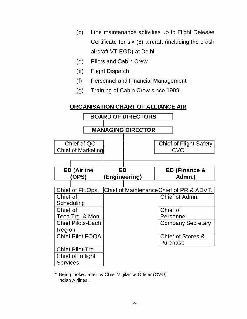
62
(c) Line maintenance activities up to Flight Release
Certificate for six (6) aircraft (including the crash
aircraft VT-EGD) at Delhi
(d) Pilots and Cabin Crew
(e) Flight Dispatch
(f) Personnel and Financial Management
(g) Training of Cabin Crew since 1999.
ORGANISATION CHART OF ALLIANCE AIR
BOARD OF DIRECTORS
MANAGING DIRECTOR
Chief of QC Chief of Flight Safety Chief of Marketing CVO *
ED (Airline
(OPS) ED
(Engineering) ED (Finance &
Admn.) Chief of Flt.Ops. Chief of MaintenanceChief of PR & ADVT. Chief of Scheduling
Chief of Admn.
Chief of Tech.Trg. & Mon.
Chief of Personnel
Chief Pilots-Each Region
Company Secretary
Chief Pilot FOQA Chief of Stores & Purchase
Chief Pilot-Trg. Chief of Inflight Services
* Being looked after by Chief Vigilance Officer (CVO), Indian Airlines.
63
1.18 INITIAL ACTIONS
Immediately after the accident, the Director General
of Civil Aviation, India (DGCA) appointed Shri P Shaw,
Controller of Air Safety, Eastern region, Kolkata as the
Inspector of Accident.
The DGCA also appointed teams of experts from
DGCA and the airline industry to collect data for the
Inspector of Accident. Experts from other fields such as
Forensic Science, Explosives, Security and Boeing joined
the teams.
Detailed examination of the wreckage was carried
out to establish the configuration of the aircraft at the time
of the crash. The Flight Data Recorder (FDR) and the
Cockpit Voice Recorder (CVR) were located and removed
for safe custody. The tapes of conversation between ATC
and the aircraft at Patna and Kolkata were heard,
transcripts prepared and kept in safe custody.
The entire history of the aircraft from the time of its
manufacture had been preserved in the form of log books.
The data about hours and cycles flown, maintenance
checks carried out, Airworthiness Directives,
Modifications and Service Bulletins complied etc. was

64
being continuously recorded and preserved. These
records were sealed and kept in safe custory.. Similarly
each engine had it’s own log book with similar data.
These log books and all other documents pertaining to
the aircraft were sealed and kept in safe custody.
The records pertaining to training, Pilot’s licenses,
medical examinations and refreshers of the operating
crew members were collected.
The records of the navigational aids at Patna Airport
such as ILS, DVOR, DME, etc. with their serviceability
and calibration reports were collected. The calibration
check of the ILS was carried out using the check aircraft.
The records of the AAI fire services were also collected.
The Inspector of Accident scrutinised the
documents collected which are mentioned above

65
2 ANALYSIS
2.1 Airworthiness Aspects
The aircraft had been operating with Indian Airlines
since its manufacture in June, 1980 by Boeing. The
aircraft records show that the aircraft sustained damage
to its Right Wing tip due to contact with the runway
surface during a Go Around initiated close to the ground
at Trichurapally in Tamilnadu, India on 15th January,
1986. The repair was carried out and after that the
aircraft had continued to fly satisfactorily.
7 ‘C’ check, which is the highest category of major
check for B737-200 aircraft, was undertaken between
November, 1999 to January, 2000. The aircraft
underwent a 20-year ageing aircraft modification
programme and Corrosion Prevention and Control
Programme (CPCP) inspection & repair. These two
programmes were part of the industry wide effort to
eliminate the effect of fatigue and age on the aircraft
structure. These programmes were developed in
consultation with the manufacturer, various airline
representatives (including Indian Airlines, Air-India),
Federal Aviation Administration (FAA) of USA and other
industry bodies such as IATA, ATE etc. Accomplishment
of these programmes ensured that the aircraft structure

66
was safe to continue beyond its Design Service Objective
(DSO).
Scrutiny of the completed checks indicated that the
aircraft was in a satisfactory condition. Its structure was
inspected thoroughly and all the inspection findings were
attended to.
All the required Airworthiness Directives,
modifications and inspections were complied with. The
Engineering Department of Indian Airlines, Delhi carried
out the 7C check on this aircraft. The engineering
organisation had the approval of DGCA to undertake the
scope of work of the 7C check of Boeing 737-200 aircraft.
The Engineering Department of Indian Airlines was
carrying out the maintenance and inspection of Boeing
737-200 aircraft since its induction in the year 1969.
Indian Airlines was, therefore, adequately experienced to
undertake the maintenance and inspection work of
Boeing 737-200 aircraft.
The work on the aircraft had been undertaken as
per the manufacturer’s guidelines. In addition, extra tasks
were performed as per in-house experience. The aircraft
undertook its first flight after the major check on 1st
February, 2000 and was in continuous service since then.
It had accumulated 1305 hrs. of flying at an average of 8

67
hrs. flying per day in the preceding 5½ months from 1st
February to 17th July, 2000,. In this period, it also carried
out 1577 landings.
All the intervening checks were carried out well
ahead of the maintenance schedule and no check was
overdue at any time. The defect history of the aircraft
indicated that there were no serious defects in the 5½
months of operation since check 7C. In the flight controls
chapter, two defects were reported. One defect was
reported thrice between 24th February, to 10th March,
2000 pertaining to Flap Lever being stiff between 0 to 1
and 1 to 0 positions. Inspection and lubrication of the
cable system was carried out, after which, the defect was
not reported again.
The other defect related to LE Flap number two
Transit Light remaining ‘ON’. Replacement of the
proximity sensor resolved the problem on the same day it
was reported i.e. 29th June, 2000.
In Hydraulics Chapter (29) one defect related to
observation of hydraulic leak on ground from a pinhole on
the full extend line of LE Slat NO. 1, inboard of LH engine.
There was no loss of pressure or difficulty in Slat
extension reported. The defect was rectified by perma-
swaging (a Boeing approved repair procedure for

68
hydraulic lines where external sleeve is swaged on to the
line) of the line in two places.
In all, there were 396 write-ups in the last 165 days
of operation. None of these defects were considered to
be of a serious nature which might have had a bearing on
the accident. In general, the rectification action was not
delayed or deferred for any period longer than necessary.
There was no apparent lack of spares or manpower to
support maintenance of the aircraft.
The post crash period saw a number of comments
about the safety of aging aircraft. The safety of any
aircraft depends on the maintenance standards that are
being adopted. A poorly maintained aircraft may not be
old but may still be unsafe. The integrity of the structure
decides the continued safety of an aircraft.
The structure of the aircraft is affected by fatigue
and corrosion. The manufacturer and the regulatory
agencies have addressed these issues by incorporating
various requirements during the operation of an aircraft.
The structure is subjected to repetitive inspections
using different techniques such as detailed visual
inspection, Eddy current and ultrasonic inspections, X-ray
and radiographic inspections etc. These inspections are

69
carried out at intervals, which depend on usage of aircraft
as well as the calendar. Increased utilisation means more
frequent inspection. However, an aircraft with low
utilisation is also inspected at fixed intervals of time.
Various parts of the structure, which are susceptible to
fatigue, undergo mandatory modifications to improve the
reliability of the structure.
The systems of an aircraft are subjected to various
inspections and operational and functional checks. The
components of an aircraft including engines, undergo
inspection, overhaul and functional check to ensure
continued serviceability.
From the time of its manufacture the aircraft is
subjected to continued airworthiness programme to
ensure the safety of operation. The honorable Chief
Justice of the Mumbai High Court had the following
comments to make about the effect of age on the safety
of an aircraft, while ruling over a Public Interest litigation
on 12th January, 2001 (Writ petition No. 3921 of 2000).
QUOTE
“We have, therefore, reached the conclusion that
the mere fact that an aircraft has crossed its design
economic life does not make it unsafe for flying,
though it may adversely, affect the profit-earning

70
capacity of the operator on account of its high cost
of flying in view of the heavy cost of maintenance,
repairs and replacement of parts. However, if such
an aircraft is properly maintained in accordance with
the instructions of the manufacturers and the
directions issued from time to time by the aviation
authorities, such aircraft can be flown for many
years after it has crossed its design economic life. “
UNQUOTE
The Court agrees with these comments. The safety
of the aircraft depends on Standards of Maintenance,
which in this case, were found satisfactory.
2.2 Weather
The visibility at 0720 hrs. was 4000 meters with
morning haze. The wind was calm with temperature of
30º C. Hence, weather was not a considered to be
contributory factor for any of the actions taken by the
crew.

71
2.3 SABOTAGE ASPECTS
2.3.1 Explosives Examination
The wreckage, the crash site and the surrounding
area was subjected to the above examination by the
Bomb Disposal & Detection Squad (from Kolkata office)
which is a part of the Bureau of Civil Aviation Security. In
their report these experts concluded that there was no
explosion on board the aircraft prior to the crash. There
was also no material evidence to indicate that there was
an explosion on the ground after the crash. The report
ruled out sabotage as a cause of the crash.
2.3.2 Fire
The crash site was approximately five to six km. by
road from the Airport Terminal. The normal practice of
taking out one or both Crash Fire Tenders (CFTs) on
every arrival and departure of an aircraft was followed on
17th July, 2000. The crash crew were supposed to have
been in their respective positions in readiness for any
eventuality. However, the crash crew were short by two
members on that day.
On 17th July, 2000 both CFTs were waiting for the
arrival of flight CD-7412 at Patna. Since, the crew of the

72
CFTs had a clear view of the approaching aircraft and
could see for themselves, the aircraft descending,
disappearing behind the trees and the column of smoke
indicating a crash. This was followed by the crash siren,
crash alarm and announcement over the public address
system by the duty Air Traffic Controller.
Both the CFT crews stated that they reached the
crash site within five to six minutes of the alarm. This
was unlikely as the distance and traffic conditions at
Patna would have prevented them from reaching the site
in less than 10 to 12 minutes. Many eyewitnesses present
at the crash site have supported this. Out of the two
CFTs, only one was able to function as the other had a
mechanical breakdown after about three minutes of
operation. The CFT had the capacity to deliver foam from
the monitor for approximately three minutes. Foam
delivery was limited by the capacity of the water tank of
the CFT
The CFTs had a provision to draw water from tanks
or shallow wells and use it for fire fighting. However, no
such source of water could be located and one CFT had
to return to the Airport for water. The City Fire Brigade
joined the fire fighting effort after about 30 to 40 minutes
of the crash message being circulated.

73
Airports are graded as per the capacity of the fire
services they can provide. International Civil Aviation
Organisation (ICAO), a body of United Nations (UN) has
laid down the standards in this regard. The size of the
aircraft that can land at any airport is decided, amongst
other things, by the category of the fire services. As per
the above standards, Patna airport required one CFT,
which was category V. This was adequate for Airbus
320/Boeing 737 operation. However, Airports Authority of
India (AAI) maintained category VI i.e. two CFTs, which
was higher than required.
As per ICAO Annexure 14-Aerodromes, Volume-I,
Para 9.2.19, the operational objective of the rescue and
fire fighting service, should be to achieve response times
of two minutes and not exceeding three minutes, to the
end of each runway, as well as to any other part of the
movement area, in optimum conditions of visibility and
surface conditions.
Since, the crash site was five to six kilometers away
from the Fire Station of AAI by road, it was felt that there
was no undue delay on part the of the Airport Fire
Services to reach the crash site and start rescue
operations.

74
The principle objective of the Airport Fire Services
was to control the fire in such a way as to allow rescue of
the passengers to commence quickly and save lives. It
was supposed to cover the Airport and its immediate
vicinity. In this respect, the Patna Airport Fire Services
equipment met the requirement. The failure of one CFT
was attributed to an airlock in the fuel line, which was
rectified by the AAI workshop mechanic in about 1½
hours. By this time, the need for fire fighting had greatly
reduced.
There was no doubt that the second CFT would
have contributed to the rescue operation since it was the
first to reach the site. However, it was possible that
someone from the surging crowd might have stepped on
the fuel line disturbing its connection. This exposed fuel
line has been provided with a protective cover
subsequent to this accident. AAI may look into the
requirement to provide protective covers to all similar
CFTs in their inventory.
2.3.3 Crowd Control
The Gardani Bagh area was a densely populated
low-lying area with narrow roads and slushy shoulders.
The CFTs of Airport Fire Services and even the City Fire
Brigade Fire Tenders encountered considerable difficulty

75
while attempting to reach the crash site due to this
topography. (Refer Annexure “A” for Wreckage Diagram).
There was no doubt that the local residents of the
surrounding area were the first to start rescue operations
to help the passengers and risked their lives in the
process. The Civil Lines at Patna where senior
functionaries of the Bihar Govt. including the Chief
Secretary and Police Officials reside was next to the
crash site. This proximity to the crash site enabled them
to reach there within minutes. This was extremely
fortuitous as they were able to mobilise State Govt.
resources for fire fighting and rescue rapidly.
Unfortunately the crowd which had collected within
a short time was of unmanageable proportions and
definitely hampered the passage of rescue vehicles.
According to witnesses, even though there was no
outbreak of violence, crowd tempers ran high and there
was a general tendency to target anybody in uniform or
position of authority with verbal abuse and physical
violence. The Airport Fire Service personnel, Indian
Airlines staff, police personnel and even the Chief
Secretary himself were victims of ire from the crowd. At
times, there were hundreds of people trying to climb on to
the rescue vehicles to get a better view. This definitely

76
slowed down rescue efforts. (Refer Annexure ‘B-1’,’B-2’
and ‘B-3’ showing photographs of the crowd)
Arrival of Bihar Military Police Jawans of the Police
Training College and the Army contingent finally brought
the situation under control. Their arrival helped rescue
operations to continue till all the dead bodies were
extricated from the wreckage. However, tension prevailed
in the area for a few days and the investigating teams had
to seek police protection at times.
In general, the rescue operation commenced
without any delay. When the crisis occurred, the
response of the people at all levels was prompt and
praiseworthy. However, this effort was hampered by the
unmanageable size of the crowd and resulting mob
mentality.
(Please refer to the photographs at Annexure ‘B-1’,
‘B-2’ and ‘B-3’)
2.4 ANALYSIS OF FLIGHT RECORDERS
(Refer Annexure B-12, B-13 and B-14 for DFDR & B-15,
B-16 and B-17 for CVR photographs.
Also refer Annexure ‘C’ for CVR transcript and ‘D-1’, ‘D-2’
and ‘D-3’ for FDR plots and ‘H’ for FDR ground track)

77
2.4.1 Flight Data Recorder (FDR) Analysis
The aircraft had arrived at Kolkata on the night of
15th July, 2000 at 2200 hrs. after operating the Kolata-
Ahmedabad-Jaipur-Kolkata sectors.
The aircraft was on ground throughout Sunday, 16th
July, 2000, as there was no requirement for its utilisation.
It was observed that there were neither Pilot reported
defects nor defects under Minimum Equipment List
(MEL). All required checks were satisfactorily completed.
Scrutiny of the ATC tapes at Kolkata (CCU)
revealed that the departure from Kolkata was normal and
routine. Witnesses who had completed the departure
formalities confirmed this.
The aircraft took off at 0651 hrs. and was estimated
overhead Patna at 0736 hrs., after a flying time of 45
minutes. The Kolkata Area Control tracked the progress
of the flight on the MSSR (Monopulse Secondary
Surveillance Radar). Scrutiny of these tapes revealed
that the aircraft had maintained it’s assigned altitude and
the W52 track.
This monitoring was possible up to SAREK (an
aerial reporting point with coordinates N24 08.0 E086

78
46.0) and slightly beyond after which the aircraft went out
of range of the radar. The aircraft reported crossing
SAREK at 07:11 hrs. and was on a heading of 315º at
FL 260 (its assigned cruise level). The aircraft reported to
Patna ATC two minutes after crossing SAREK and
obtained clearance as well as the Meteorological (MET)
report. Eight minutes after crossing SAREK at 07:19 hrs.,
the aircraft was cleared to descend to 7500 feet and told
to report 25 NM (Nautical Miles) from Patna DME
(Distance Measuring Equipment). The aircraft reported
that it was 25 NM from Patna at 07:26 hrs. ATC cleared
the aircraft to descend to 4000’ and join the ILS-DME
ARC approach at 13 NM on DME.
Analysis of the FDR data indicated that the aircraft
then deviated right from the W52 track of 315º to a
heading of 329º. This happened at approximately 21 NM
on the DME. (Refer Annexure ‘D-3’ for heading plot of
last six minutes)
Patna ILS-DME ARC Approach procedure was
introduced on 24th March, 2000. The procedure
connected the W52 Track coming from Kolkata to a
constant radius turn at 11 NM maintaining a height of
2000’ up to the Lead Radial at 080º. After crossing the
Lead Radial, the aircraft had to turn on to the Localizer
Beam at a height of 1700’ and then follow the Localizer

79
and GS commands. With this procedure, the aircraft was
established on the runway centre line at 6 to 7 NM and
stable approach was achieved for a proper landing.
(Refer Annexure ‘E-1’ and ‘E-2’ for the above procedure
at Patna airport)
At 07:28 hrs., the aircraft informed ATC
“Commencing the ARC 7412, call you established
Localizer, to which Patna ATC replied “Descend to 2000’
QNH 997 hPa. Report crossing Lead Radial 080 PPT”.
The FDR data indicated that the aircraft did not
commence the ARC but continued on the same heading
of 329º. The aircraft would have had to turn right through
60º to 70º to join the ARC and thereafter, execute a slow
but continuous left turn to 250º to align with R/W 25.
However, no such maneuver was recorded. The aircraft
was supposed to descend to 2000’ while flying the ARC
approach but the FDR data indicated that the height
remained at 4000’ even two minutes after reporting
“Commencing the ARC”.
The FDR Heading data further showed that the
aircraft then slowly started turning left from 329º to 323º
again right to 327º and back to 321º. During these 3½
minutes, the configuration of the aircraft changed from

80
Flaps UP to Flaps 1, Flaps 5, Gear down, Flaps 15. At
07:26 hrs., the aircraft reported to ATC “7412 crossing
Lead Radial and coming up on Localizer”. The ATC
replied back “Descend to 1700’ QNH 997 hPa, report
establishing Localizer”.
As per the Approach procedure at the crossing of
Lead Radial 080, the aircraft should have been at 11NM
from Patna DME and at 2000’. In actual fact, it was
estimated that the aircraft was at approximately 3.5 NM
and at 3000’. It must have crossed the R/W 25 centre
line almost immediately while maintaining a heading of
320º. (Refer Annexure ‘H’ for ground track)
On the Approach Chart, at 3.5 NM, the aircraft
should have been well established on the Localizer and
tracking the Glide Slope, aligned with the runway centre
line. The height should have been about 1400’. After
crossing the runway centre line, the heading data
indicated that the aircraft started turning left from 320º to
231.5º. During this time, the configuration changed to
Flaps 40 from earlier Flaps 15. The heading again
started changing to the right from 231.5º to 240º.
At 7:32:26 hrs, the last communication from the
aircraft to Patna ATC started in which permission to carry

81
out a 360 due high on approach was requested. This was
the point at which a decision must have been made to
discontinue the approach and do a 360º turn and make a
fresh approach. The aircraft was estimated to have been
at a height of 1280’ and at a distance of 1.2 NM from the
threshold of R/W 25. As per Approach Charts, at 1.2 NM,
the height should have been between 610’ to 650’.
At 07:32:45 hrs., the communication with Patna
Tower ended. The aircraft which was in a left turn,
started a right turn just as the transmission ended which
was again reversed to a steep left turn and then a right
turn. In approximately 15 seconds, the FDR recorded
bank angle changes from Left 21º to Right 14º to Left
47º to Right 30º. After the decision had been made for a
360, the Nose Down pitch attitude of the airplane
reversed to airplane Nose UP first to 8º and then to a
peak of 16º. The CVR recorded Stick Shaker activation,
which was an advance warning of approach to a Stall at
07:32:51 hrs., six seconds after the last transmission was
made. The sound of the Stick Shaker was heard
continuously till the end of the recording.
Within two seconds of Stick Shaker activation,
engine thrust was increased to 1.84 EPR and the Flap
Lever was moved to 15º gate as indicated by a click

82
sound on the CVR. The Pilot called out for gear retraction
(GEAR OOPER LELO). This was followed by a click
sound indicating operation of the Gear Lever.
The Gear Unsafe Warning sounded at 07:32:56 hrs.
This was indicative of the Flaps transiting from 40 to 25
(Gear Unsafe Warning sounds when Landing Gear is not
locked down and the Flaps are in landing configuration
i.e. 25 to 40. This warning cannot be silenced by the
horn cancel button.
The Gear Unsafe Warning stopped sounding as
soon the Flaps moved from 25 upward towards its
commanded position of 15 as found in the wreckage. The
Ground Proximity Warning “Whoop Whoop pull up”
started sounding at 07:32:58 hrs. and continued. The
CVR recorded the sound of crash at 07:33:01 and the
recording stopped thereafter.
Scrutiny of parameters recorded in the FDR
indicated that from the time the aircraft was cleared to
descend from Flight Level (FL) 26000 i.e. at
approximately 07:20 hrs., the engines were throttled back
to idle and remained at idle till 07:32:45, i.e. 15 seconds
before the crash. Even though the aircraft was being
maneuvered, the engines remained at idle.

83
The Indicated Air Speed (IAS) record showed that
the speed had continuously reduced to the lowest value
of 119 Kts (Nautical Miles/Hr). This air speed was the
same as VREF for Flaps 40 landing at an aircraft weight of
40 tonnes (VREF is the speed, which the aircraft is
supposed to attain when it is about to touch down).
In this respect, the Boeing 737 Operators Manual
stipulates the following procedure for an approach.
QUOTE
“When the wind is reported calm or light and
variable and no wind shear exists VREF+5 Knots
is the recommended air speed on final, bleeding
off the 5 Knots as the aircraft approaches
touchdown. UNQUOTE.
In effect what it meant was that the airspeed should
have been much higher than 119 Kts, at least 124 Kt, if
not more. When the final communication was started with
Patna Tower, the speed recorded was 130 Kts. By the
time, the transmission was completed 16 seconds later,
the speed had dropped to 122 Kts and thereafter to 119
Kts.
This speed reduction did not appear to be
intentional. It meant that the Co-Pilot (flying the aircraft

84
from the left seat) was not concentrating on flying. He
was probably looking out for the runway and judging the
situation or his attention was diverted to what the
Commander (sitting on the right seat) was conveying to
Patna Tower, which had caught him unawares. The
Commander was probably busy with the conversation.
Either way it appeared that both Pilots had failed to notice
the drastic reduction in air speed. The turn was probably
started without realising that the air speed had reduced to
119 Kts.
The aspect of Engine Thrust Management was
examined closely since the engines had remained at idle
power throughout the descent. The Boeing 737
Operation Manual did not mention the engine thrust
requirement directly but the requirement of air speed was
specified at various places. It was for the Pilot to judge
and use adequate engine thrust so as to maintain the
required air speed. Experienced Boeing 737 Pilots whose
views were sought in this respect, were all of the opinion
that using at least 1.40 EPR with Flaps down was a safe
practice. (Refer Annexure ‘B-9’ and ‘B-10’ for
photographs of engine)
It was not clear why the engines were kept at idle
thrust even after selecting Flaps 40. It was perhaps
because the aircraft was higher than normal on approach.

85
If the intention was to regain the correct glide path then
classic flying technique would have required the Pilot to
maintain speed by reducing the angle of attack i.e. by
pushing the control column forward while allowing the
aircraft to regain the correct glide path with an increased
rate of descent. The old adage that “the Stick (control
column in an airliner) controls airspeed and power
controls the glide path” continues to be true even for
modern jet airliners. There was little doubt that a higher
engine thrust setting would have prevented rapid speed
decay and delayed activation of the stick shaker. It would
have also aided quick recovery from an approach to stall
condition of flight. In this respect, an entry in the Co-
Pilot’s training records where during a simulator training
session his instructor had noticed poor thrust
management becomes pertinent. The instructor had
given him additional training before clearing him.
2.4.2 Cockpit Voice Recorder (CVR) Analysis
The sound quality of the CVR tape was good even
though the box itself was totally burned in the fire after the
accident. Since, each of the Cockpit Stations was
assigned a separate channel, it enabled confirmation of
the source of recording. (Refer Annexure ‘C’ and ‘D-1’
for CVR transcript and FDR data plot with CVR transcript
of last 40 seconds)

86
The Public Address (PA) System announcement,
which was at the beginning of the tape, created a doubt
about the seats occupied by Captain Sohanpal and
Captain Bagga. Voice recognition by the wives of the
deceased Pilots confirmed that Captain Bagga, the Co-
Pilot was seated on the left seat and Captain Sohanpal,
the Commander was seated on the right seat. Except for
the PA announcement at the beginning of the flight, all RT
air to ground communications were carried out by Captain
Sohanpal.
Much of the CVR conversation was communication
with various ATC and Tower personnel. The intra cockpit
conversation was mostly in the form of checklists and
announcements. There was hardly any conversation
between the Commander and the Co-Pilot, except for
asking for a Newspaper or commenting about moisture or
asking for the Patna frequency.
Considering the fact that it was an early morning
flight lasting for only an hour, it was possible that much
conversation was not the expected norm.
It was observed that Patna ATC was being given an
impression that the aircraft was following a “Standard
DME ARC Approach Procedure” as per the manual while

87
there was no intention to follow the ARC. It was expected
that at least the Commander would have briefed his Co-
Pilot about the procedure which was to be followed. No
such briefing was heard on the CVR.
The second glaring silence was at the time when it
was realized that the approach had not stabilized, the
aircraft was not at the correct height and was too close to
the R/W 25. There was a definite need for the
Commander to brief the Co-Pilot about his intended
corrective action.
The CVR recording, just prior to the last
conversation of the Commander with Patna ATC, had
three words from the left seat channel with the rest
drowned out by the RT communication.
The words sound as “Left hand down………or “Left
and down…….”
A series of viewpoints were considered. One view
was that the Co-Pilot wanted to carry out a missed
approach and go left hand downwind of R/W 25. The
other was that he was merely pointing out the runway
location.

88
Either way this brings into picture a conflict of views,
which the Commander decided to resolve in a completely
different manner without any discussion with the Co-Pilot.
The procedure to carry out a 360 was not an
authorised procedure as per the Alliance Air Operations
Manual and could have caused considerable confusion in
the mind of the Co-Pilot. It was clear from the FDR
recording that the aircraft was not following the DME ARC
ILS procedure but Patna ATC was being given the
impression that the aircraft was doing so.
At any busy airport with some more traffic, this
would have been unthinkable and would have created a
conflict. However, there was no other traffic for miles
around Patna and ATC gave the permission, only after
confirming that the crew had the airfield in sight.
2.5 Circumstances Leading to the Crash of the Aircraft.
Approximately 8 seconds before impact, the stick
shaker warning was activated. At initiation of warning, the
configuration of the aircraft was, “Flaps 40, engine thrust
at 1.5 EPR, Speed at VREF-119 Kts., Pitch Attitude-10º
Nose Up, Left bank at 20º (just out of a rapid bank
reversal)”.

89
Under normal circumstances, the stick shaker was
expected to be activated at a speed much below 119 kts.
However, a rapid roll reversal with higher than normal
Nose Up pitch attitude might have activated the stick
shaker at higher speeds. Simulation exercises were
carried out at the B737-200 Flight Simulator at Central
Training Establishment, Indian Airlines Ltd., Hyderabad.
Repeated simulations with the same kind of maneuvers
that were seen on the FDR always resulted in activation
of stick shaker at speeds between 118 Kts. to 122 Kts.
However since there was no provision to record flight
data, the load factor in all these simulations could not be
ascertained.
Boeing carried several studies involving
mathematical simulations and analysis of wind tunnel
data. They were of the view that a significant loss of lift
equivalent to 18 Kts. of speed had occurred. They did not
agree with the view that the stick shaker had activated at
a higher speed due to maneuver of the aircraft as the
FDR had recorded a load factor (vertical acceleration)
close to 1g. They said that such a low load factor was not
likely to trigger activation of the stick shaker. They carried
out studies with various changes in the configuration of
the aircraft. These consisted of deployment of Speed
Brakes in flight, Single Flight Spoiler extension, High Lift

90
Devices Trailing Edge Flaps and Leading Edge Flaps out
of commanded configuration.
The simulation and studies had eliminated all, but
one, configuration about Leading Edge (LE) Devices not
being in their commanded position i.e. fully extended.
This study in part was dependent on the examination of
the Actuators of the LE Devices found in the wreckage.
Initially, these were not in the list of parts for which Boeing
had asked for laboratory tests to be conducted on.
However, on 20th December 2000, five months after the
accident, Boeing requested the Court for permission to
examine them at the Equipment Quality Assurance (EQA)
Laboratory at Seattle, WA, USA.
Out of a total of 10 actuators, seven were sent to
Boeing, two were not located and one was examined in-
situ, still attached to a portion of broken wing. Of the
eight actuators, one was found fully extended, another
was fully retracted and locked. The other six were in a
partially extended position. The extension was such that
both inner and outer pistons had unlocked and extended.
As explained earlier, the actuator had a hydraulic blocker
valve, which was supposed to keep the Leading Edge
Slats and Flaps from blowing back with loss of hydraulic
pressure. (Refer Annexure ‘B-11’ for photograph of Slat
Actuator No. 5)

91
Hence, it was expected that the actuators, if they
had been fully extended, would have maintained their
position even after impact with the ground. In support of
this, Boeing produced photographs of actuators from
another accident to a Boeing 737-200 aircraft with
Registration Mark-N999UA of United Airlines Flight UA-
585, which had crashed at Colorado Springs, USA in
March, 1991. The aircraft had entered a nearly vertical
dive and impacted the ground nose first. Most of the
actuators were severely damaged but were found to be in
the fully extended position.
The actuators, which were recovered in the
wreckage at Patna, were mostly in an undamaged
condition, even though they had been subjected to impact
loads and burned in the post crash fire. The only
actuator, which was severely damaged, was the one with
full extension. Its housing was damaged and cracked in
several places, which had probably not allowed the
pistons to retract post crash. Boeing stated that the
actuator had extended due to vapourisation of the
hydraulic fluid during post crash fire.
On its final flight path, the outboard portion of the
right wing had broken off, when a tree had torn through
the wing. This portion of the wing separated and fell near

92
the trees next to the crash site. A photograph of the wing
portion with No. six LE slat clearly indicated that the LE
Slat was extended. (Refer Annexure ‘B-8’ for photograph
of No. 6 LE Slat and ‘B-6’ and ‘B-7’ for the final flight path
of the aircraft).
The rest of the aircraft, with landing gear in
retracted position, hit the ground, with the engines
contacting the ground first and taking the impact of the
wing. The aircraft also brought down two brick houses
and the wings were buried under the earth.
It was not possible to estimate the loads and forces
the LE slats and flaps had been subjected to at impact.
The aircraft wreckage had to be moved around to recover
bodies trapped under it. This was done using mechanical
shovels and equipment. The Court carried out laboratory
tests on the LE Slat Actuator at the Indian Airlines,
Engineering Facility at Delhi. The test was aimed at
understanding the retraction of actuator pistons from the
fully extended position with no hydraulic pressure and
external force applied to retract them. It was observed
that a sustained force of approximately 150 kgs. was
sufficient to start a slow retraction of pistons. This force
could have been applied while shifting the wreckage to
search for bodies or even with a number of persons

93
standing on the wreckage. (Refer Annexure ‘B-3’ and ‘B-
4’ for photographs of the rescue operation)
It was necessary to make several assumptions to
invent a scenario of LE Slats and Flaps remaining out of
commanded position. Following was the sequence of
assumptions as suggested by Boeing.
(A) The aircraft on its departure from Kolkata (CCU)
had to have a fully functional LE Slats and Flaps
System. Otherwise, the aircraft would have had to
return to the departure gate
(B) When Flaps were selected to FLAPS 1, the LE
Flaps and Slats did not extend. The Amber Light
“FLAPS IN TRANSIT” came on, but the crew
ignored the warning and did not even mention it to
each other since nothing was recorded on the CVR.
Alternately, the indication system had also
malfunctioned. Refer Annexure ‘L’ for indication
panel of LE Devices)
(C) When Flaps were selected to Flaps 15, again, the
LE Slats did not go to the full extend position and
the crew ignored the warning again. Alternatively,
the indication system had again malfunctioned.
This would amount to a third malfunction in the

94
Leading Edge Devices Extension and indication
system. The crew had not mentioned it to each
other since the CVR had not recorded any such
conversation.
(D) When the Stick Shaker activated and the crew
initiated a Go Around procedure and raised the
Flaps to 15 from 40 followed by gear retraction, the
aircraft stalled and started loosing height rapidly.
The crew then realised that the LE Devices were
not in the commanded position. After the Flaps had
moved to 15 position, the Co-Pilot looked up at the
overhead panel, reached out and selected Alternate
Flaps to ARM and Flaps Switch to Down (to extend
the LE Devices).
The aircraft crashed three seconds later.
The last assumption (D) became necessary in view
of the fact that the LE Slat Actuators had both the pistons
extended by a few inches at least. As explained earlier,
the LE Slat Actuator follows a sequence of extension with
inner piston extending first at Flaps 1 and outer piston
thereafter at Flaps 10, when they are extended normally
using Hydraulic System ‘A’. It is only when the Flaps are
selected to ALTERNATE FLAPS ARM and DOWN the
inner and outer pistons extend simultaneously using the
95
Standby Hydraulic System. (Refer Annexure ‘J’ for Flight
Control panel diagram and ‘I’ for hydraulic diagram of LE
Devices))
However, with the Alternate Flaps selected to ARM,
the normal operation of the Trailing Edge Flaps with the
System ‘A’ hydraulic motor is stopped. Any further
operation had to be carried out electrically by the Pilot on
the left seat (in this case the Co-Pilot) selecting the Flaps
Control Switch to UP or DOWN. The CVR timing of Flap
retraction and Gear unsafe warning indicated that the
Trailing Edge Flaps had retracted hydraulically. That
meant, the Co-Pilot on the left seat, had to wait till Flaps
had moved to 15 and then select the Alternate Flaps to
ARM and select Flaps DOWN. By this time, the aircraft
was probably very close to hitting the trees. It was highly
unlikely that a pilot flying the aircraft would leave the
Control Column and reach for the Flaps Switch with the
aircraft undergoing post stall gyrations. The autopsy
report of the Co-Pilot’s body revealed that he had injuries
on his hands and feet which indicated that he was
gripping the Control Column and had his feet resting on
the Rudder Pedals at the time of the crash.
Considering the flight conditions (the aircraft had
commenced post stall gyrations at this time) and the time

96
available to the Co-Pilot to use the alternate system to
extend the LE Devices, this scenario is ruled out.
Boeing presented a plot of Lift Coefficient against
Angle of Attack. It was argued that the plot from FDR data
matched that of wind tunnel test data for an aircraft with
LE Slats retracted. However, this data had not been
validated by any flight tests.
The Boeing 737 landing with LE Devices not in
correct position, required a Flaps 15 landing with speed
being maintained at VREF+5 Kts i.e. 134 Kts in this case.
The use of Flap 15 in the case of LE Devices not in
correct position is to allow a Go Around procedure to be
executed, if necessary. A normal Flaps 15 landing is at
129 Kts (for a landing weight of 40 Tonnes). These
figures were obtained from Quick Reference Handbook of
B737 airplane at CTE, Indian Airlines, Hyderabad.
Boeing argued that even if the LE Devices remained
retracted, there was no question of the aircraft going out
of control. The aircraft would not have encountered loss
of lift if adequate speed was maintained. Even if a loss of
lift situation had arisen due to reduction in speed, the
aircraft would not have stalled if prompt Approach to Stall
recovery procedure had been initiated when the stick

97
shaker activated. (Refer Annexure ‘M’ for Approach to
Stall Recovery procedure)
Considering all the above aspects, it did not seem
probable that an aircraft would develop multiple defects
and the crew would ignore all warnings and continue the
flight without taking timely corrective action. Even Boeing
admitted that such a pattern of failure had not been
reported to them by any operator in the past. There have
been instances of a single Slat or Flap indication failure,
always accompanied by warning light, but Boeing could
not quote an instance where complete failure of a system
along with indication failure, had occurred.
The plot of Lift Coefficient against Angle of Attack
submitted by Boeing may be mathematically correct but in
the absence of validation by Flight Test, it was difficult to
determine the difference in performance of the wing in the
two configurations (Slats normal and Slats retracted).
The difference between the two configurations as far as
landing speed was concerned, was only five Knots. It
was probable that the plot represented the actual
performance of the wing with Slats fully extended.
Detailed analysis of the graph of kinematically
corrected pressure altitude against the time scale
revealed that there were three distinct changes in the
98
slope of the curve which otherwise had a smooth rate of
descent. At 16 seconds before the crash, the spooling up
of the engine had reduced the rate of descent. However,
eight seconds later when the Flap Lever was moved to
15, the rate of descent increased as seen by the
steepening of the slope of the curve. This was caused by
loss of lift due to the reduction in wing area as the flaps
moved up from 40 to 15. (Refer Annexure ‘D-1’ for FDR
plot of last 40 seconds)
Six seconds after the Flap Lever was moved to 15,
the rate of descent increased even further indicating that
the flaps were close to 15 position and the wing no longer
generated enough lift to support the aircraft. This high
rate of descent together with the high Nose Up pitch
attitude held by the Pilot resulted in the aircraft attaining a
very high Angle of Attack of the order of 26º. The aircraft
had completely stalled by this time and even though
thrust had been increased to the maximum possible on
both engines, recovery was not possible
Extrapolation of the curve before the Flap Lever
movement indicated that the aircraft would have certainly
recovered from the approaching stall if the flaps had not
been disturbed. Adequate engine power and reduction of
Angle of Attack by reducing the pitch attitude would have
allowed the aircraft to fly out of the hazardous situation.

99
2.6 Pilot Factor
It was clear from the CVR tape that the atmosphere
in the cockpit was relaxed and tension free till 15 seconds
before the crash.
There was no mention of any abnormality or
malfunction of any system of the aircraft. The
configuration of the aircraft was changed from Clean
Cruise Configuration to Landing Configuration of Flaps 40
and Gear Down approximately 2 minutes 20 seconds
prior to the crash.
Even when the decision for a 360º turn was
conveyed to Patna ATC, there was no sense of anxiety or
apprehension in the voice of Captain Sohanpal.
However, the element of surprise must have been there
having sighted the field so near, with the aircraft much
higher than expected.
It was not clear whether the Co-Pilot (Flying from
Left Seat) understood the decision of the Commander
(Flying from right seat) to make a 360º turn instead of a
Missed Approach Procedure which, probably, was in his
mind. (Left hand down…).
100
In all probability, the heading change to the Right
seen on the FDR was either for a missed approach or to
make an “S” approach to lose height and still try to effect
a landing. (“S” approach is resorted to in VFR conditions,
when the aircraft is high on approach and cannot lose
sufficient height with a straight-in approach. The aircraft
is maneuvered in a zigzag manner to lengthen the
approach path and enable loss of excess height).
However, within two seconds of end of conversation with
Patna ATC, the aircraft reversed its bank by rolling to the
left and the pitch attitude increased to 12º nose up.
The sound of stick shaker activation was clearly
heard on the CVR. However, there was no verbal
comment from either pilot. The next sound heard on the
CVR was most probably that of the flap lever hitting the
gate at 15 position. (Refer Annexure ‘K’ for Flap Lever
operation)
The first sign of anxiety became apparent only when
the Co-Pilot called out “Gear Ooper Lelo” (Raise the Gear
up). By this time, the aircraft had probably entered a full
aerodynamic stall and the controls were no longer
effective (as is to be expected in a stall). There were no
more comments from the crew except for a “Noooo-“
exclamation by the Commander.

101
The actions of the crew i.e. full engine thrust, Flaps
to 15 and Landing Gear Up, related to Go Around
procedure. This, along with the pitch attitude of 10 to 12º
as recorded by the FDR, indicated that the crew had
initiated a Go Around to fly out of the situation. However,
activation of the Stick Shaker was a warning that the
aircraft was approaching a stall and would stall unless an
aggressive Approach to Stall recovery action was
initiated.
An Approach to Stall recovery action required that
the aircraft configuration not to be disturbed, full thrust
opened on both engines and the Angle of Attack reduced
by lowering the nose (pitch attitude). The FDR had not
recorded any of these actions, except for opening up of
the throttles of both engines that too in two steps of
medium thrust followed by full thrust only in the last
stages of flight. (Refer Annexure ‘M’ for check list of
Approach to Stall Recovery procedure).
CVR analysis revealed that during the early part of
the approach at time 22:03:4, the call for Flaps 40 by the
Co-Pilot was not acknowledged by the Commander.
However, a sound was recorded at time 22:04:8, which
sounded like that of flap lever movement. In addition after
the “Gear Ooper Lelo” call at time 22:25:06, Gear Unsafe
Warning was recorded which would have activated only

102
when the landing gear was not locked down and flaps
were moving up from 40 to 25. This was irrefutable proof
that the flaps were at 40 when the approach was
commenced.
The Gear position was acknowledged in checklist
earlier with “Down, Three Green”, which indicated all the
three gears were Down and Locked. The scenario in the
final moments was as below:
(i) The aircraft had not followed the approved
Approach procedure, but intersected the Extended
Runway Centerline with a lateral separation of
about 3 to 3.5NM and tried to align with the
centerline at a very short distance from the runway.
(ii) The engines were at idle throughout the descent
profile and the speed was continuously reducing.
(iii) When it was realized that the aircraft was too high
to effect a landing, a 360º orbit was requested. The
speed by this time had dropped to VREF 119Kts.,
which was actually the landing speed.
(iv) The aircraft was maneuvered sharply and the Stick
Shaker activated.

103
(v) A “Go Around” was initiated by retracting the flaps
to15, opening throttles, retracting the landing gear
and holding a nose up pitch attitude of 10 - 12º.
(vi) The retraction of flaps to 15 together with high pitch
attitude and in- sufficient speed caused further loss
of lift and the aircraft entered into a full stall regime,
from which it could not recover and impacted the
ground.
It was probably possible to recover from the
situation if prompt and correct recovery had been initiated
when the stick shaker activated.
The histo-pathological and toxicological analysis
was carried out on the viscera of both Pilots at the
Institute of Aerospace Medicines, Indian Air Force,
Bangalore. The report was negative.
Wing Commander Gomez, Dy. Director, Medical
Service who deposed before the Court, explained in detail
about the injuries sustained by the Pilots. He stated that
the pattern of injuries indicated that Captain Sohanpal
was occupying the left seat and Captain Bagga, the right
seat. The Court however felt that it was difficult to
conclude this on the basis of injuries suffered. The small
size of the cockpit and the unpredictable dynamics of
104
disintegration of the front section of the aircraft during its
impact with the ground made it difficult to understand the
nature of injuries suffered by the Pilots.
Wing Commander Gomez further stated that a Pilot
handling the controls during an air crash i.e. hands on
control wheel and feet on rudder pedals suffered a
particular pattern of fractures of the bones of hands and
feet. He found this pattern only on the body of Captain
Bagga. This was conclusive proof that Captain Bagga
handled the controls till the end.
2.7 ORGANISATIONAL ASPECTS
2.7.1 Quality Control Organisation
Indian Airlines was the registered owner of Alliance
Air. The organisation of Alliance Air was completely
different with most of its employees working on contract
rather than on a permanent basis. Indian Airlines was the
main source of trained personnel as their staff were
deputed to Alliance Air. Retired Indian Airlines personnel
were employed on contract by Alliance Air
Out of the 11 Boeing 737 aircraft, six were under
the control of Alliance Air Quality Control organisation.
The remaining five aircraft were under the control of

105
Indian Airlines. All the 11 aircraft were operated by
Alliance Air.
The Engineering set up of Alliance Air was
restricted to Delhi with all other stations serviced by
Indian airlines. Alliance Air had DGCA approval to carry
out checks up to 3A (flight release check) i.e. 375 hrs./75
days elapsed time. These checks were carried out by
Alliance Air only on the six aircraft under their control.
Indian Airlines carried out these checks on the
remaining five aircraft. Work on all aircraft at stations
other than Delhi and major checks above flight release
check on all aircraft was the responsibility of Indian
Airlines. Repair, overhaul and replacement of all
components including engines for all aircraft was the
responsibility of the Indian Airlines because they had the
maintenance infrastructure at Delhi and Kolkata.
The preparation of work-scope of the six Alliance Air
aircraft, was the responsibility of the Quality Control
Managers (QCM) of Alliance Air as far as maintenance of
the aircraft was concerned. However, actual work was
carried out by Indian Airlines who would then carry out the
checks under their own QCM without any reference to
their counterparts in Alliance Airlines. The QCM of
Alliance Air reported directly to the Managing Director of
106
Alliance Air while the Indian Airlines QCM reported to
their management. There was a possibility that the two
managements could take entirely different decisions for
the same fleet of Boeing 737 aircraft.
The officials of Indian Airlines and Alliance Air
including Mr. S.C. Jain, the then Director of Engineering,
Indian Airlines supported the present set up. It was
probably because the personnel on both sides had spent
most of their working life in one organisation i.e. Indian
Airlines.
The present system of dual channels of
responsibility for the same fleet of aircraft being operated
by one airline could lead to confusion and divergent
decisions. Even though there was no evidence of safety
being compromised, there appears to be a strong case to
revamp the quality control system in order to eliminate
dual control over the same type of aircraft fleet.
2.7.2 Operations
The senior management personnel of Alliance
Airlines who deposed before the Court stressed the
importance being given to Flight Safety at Alliance Air.
Crew Resources Management (CRM)l training, Flight
Operations Quality Assurance (FQOA), Voluntary

107
disclosures by the crew, CVR, monitoring, corrective
training were all being practiced proactively by the
management of Alliance Air.
In this accident, however, it was observed that there
was a general lack of adherence to standard operating
procedures on the part of the crew. The decision to carry
out a 360º turn instead of a missed approach without any
discussion with each other indicated a lack of CRM.
Adoption of the “Go around” procedure instead of
Approach to Stall Recovery procedure when the stick
shaker activated indicated that training lessons had been
forgotten.
The management of Alliance Air had also
emphasised that the recruitment and induction
procedures were designed in such way that trainee Pilots
were exposed to the airline philosophy and procedures
with enough time to absorb them at each level.
The accident provided grim proof that there was a
need to review the training curriculum of Pilots of Alliance
Air both in the simulator as well as the classroom. There
was a need to encourage Pilots to adhere to Standard
Operating Procedure (SOP).

108
2.7.2 Patna Medical College Hospital
The bodies of the fatally injured passengers were
taken to the Patna Medical College Hospital (PMCH).
Autopsies of the bodies were performed by the doctors of
the Dept. of Forensic Medicine. All the bodies were
videographed before being handed over to the
next-of-kin.
The Court visited the PMCH to gain the first hand
knowledge of the facilities available there. The facilities of
any hospital would be stretched to the limit when a
tragedy of this magnitude occurred without warning.
PMCH was no exception to this and some confusion did
prevail in the initial hours. A surging crowd had collected
at the PMCH premises within minutes of the crash. This
caused some difficulties for movement of rescue vehicles,
the relatives of the passengers and even the doctors
themselves. It was to the credit of the PMCH and the civil
administration that they brought the situation under
control and completed the necessary formalities quickly.
The Court took the opportunity to visit the mortuary,
the Casualty Ward and discussed the availability of
facilities with the Superintendent and doctors of the
PMCH. It was observed that the mortuary building and
the facilities were in need of immediate upgradation. The
109
refrigeration equipment which was meant for preserving
bodies awaiting formalities, was not functioning since its
installation in 1988. The casualty ward was in need of
routine maintenance and upkeep. The Court also felt that
there was a need to clean up the premises in general and
keep them that way.
2.8 Analysis of Infrastructure at Patna Airport
2.8.1 Patna Airport
The airfield at Patna has been in existence for more
than 40 years. The airfield had a single runway with an
orientation of 07/25. The basic strip had a length of 2074
mts. and a width of 150 mts. The Landing Distance
Available (LDA) was 1677 mts. for R/W 07 and 1820 mts.
for R/W 25. The Take Off Distance Available (TODA)
was 1954 mts. from both ends. This difference in the
LDA and TODA was due to obstructions and restrictions
at both ends.
An aircraft coming in to land on R/W 25, passed
over Patna town and keeping the secretariat tower to the
left, the aircraft passed over the zoological garden and
the airport road. There were tall trees in the zoological
garden, a part of which fell in the Approach Funnel of R/W
25. Vehicular traffic on the airport road which was close

110
to the threshold of R/W 25 also caused restrictions for
runway use. As a result, the threshold of R/W 25, was
displaced by 400 feet. Tall trees in the Approach Funnel
also affected the stability of the radio beam of the glide
path. At present, the reliability of the glide slope was only
up to a height of 300 feet. Normally for a Cat I ILS
System, the glide slope should be reliable up to a height
of 200 feet above the runway.
The main railway line on the Delhi-Kolkata route
passed very close to the southern airport perimeter wall
near R/W 07 end. Immediately to the north of the airport
perimeter wall of R/W 07, there was workshop of Bihar
State Transport Corporation. As a result of these two
obstructions, there was no basic strip (150 mts.) available
at this end of the runway. Consequently, the threshold
was displaced by 1500 feet. There was a vast open area
between the perimeter wall of the airfield and the railway
line to the south. This area was occupied by several
habitations which included meat and poultry shops.
These shops attracted birds and vultures, which posed a
serious hazard to aircraft landing on R/W 07.
Prior to the 70s except for the railway line, the trees
in the zoological park and the State Transport Corporation
workshop, did not pose any restriction. The surrounding
areas of the airfield were relatively free from human

111
habitation. Only light aircraft were being operated from
the airfield. Hence, a shorter runway, which was free
from obstructions, sufficed. The zoological garden came
into existence subsequently and was declared a reserve
forest even though it was within the city limits. As long as
only light aircraft were being operated, there were no
restrictions to their operation, which is true even today in
spite of several obstructions on either side.
The operation of big commercial jets from Patna
airport started in the 70s with the Boeing 737 and later on
in 90s, with the Airbus 320. The runway length was
extended to its present dimension, which was the
maximum the airfield could accommodate. Even with this
extension, the thresholds on either end had to be
displaced because of the restrictions mentioned above.
These restrictions caused several operational constraints.
In the summer months, the maximum take off weight that
an Airbus 320 could operate with had to be severely
restricted because of the insufficient runway length for
take off. This, in turn, meant financial loss to the Operator
and inconvenience to the passengers due to non-
availability of seats during the peak holiday season. The
biggest concern, however, was the narrow margin of
safety, with which these aircraft operated and the tension
the Pilots had to undergo because of displaced thresholds
and high trees in the Approach Funnel of R/W 25.

112
While it was understood that the runway length
could not be extended in its present alignment, it was
possible to remove at least some of the restrictions and
improve the margin of safety for normal operation of
scheduled services with Boeing 737 and Airbus 320
aircraft.
RUNWAY 25
The threshold of this runway was displaced by 400’.
This was because of trees of the zoological garden, which
fell in the Approach Funnel and the vehicular traffic on the
airport road, the latter being the controlling factor. The
Secretariat Clock Tower did not pose a restriction as it
was below a gradient of 2.5% from the runway threshold
which was within the permissible limit. The zoological
garden had 3700 trees, which fell in the Approach Funnel.
Over the years, the trees had grown tall and will continue
to grow. Pilots tend to instinctively stay above the normal
glide path because of presence of tall trees on short finals
just before the threshold. This resulted in a late touch
down further up the runway from the normal touch down
point and consequent severe use of thrust reversers and
brakes. In conditions of poor visibility, rain and at night,
this could have serious consequences.

113
It was necessary to control the height of the trees so
as to provide a clear approach path to landing aircraft.
The pruning of trees had to be done on a continuous
basis since in the fertile Gangetic Plain, trees grew
quickly. Alternatively, the Approach Funnel should be
totally denuded of all tree cover.
Vehicular traffic on the airport road should be
relatively easy to control. Traffic could be diverted on a
different route which is readily available. The second
option would be to allow only vehicles with restricted
height i.e. passenger cars and stop the passage of buses
and trucks on this stretch of road. All traffic should be
stopped during the arrival and departure of aircraft.
RUNWAY 07
This threshold at this end of the runway was
displaced by 1500 feet because of non-availability of the
basic strip. The restoration of the basic strip for the entire
1500 feet required rerouting of the main railway line and
shifting of the Phulwari Railway Station, which was next to
the runway. To the north, the Transport Workshop
needed to be shifted. Rerouting of the railway line may
prove to be a difficult task. It may, however, be possible to
extend the basic strip by a certain length without affecting
114
the railway line and this would help to increase the
available runway length.
2.8.2 Air Force Station Bihta
Air-Force Station Bihta was approximately 32 kms.
south-west of Patna city. The runway length available at
this airfield was 8200 feet. This airfield was totally free of
the type of the obstructions existing at Patna airport.
Shifting scheduled airline traffic from Patna to Bihta could
be an alternative solution. However, the existing runway
needed to be strengthened to allow operation of Airbus A-
320 class of aircraft. There were no facilities for handling
of aircraft, passengers and baggage. A new Terminal
Building with Control Tower and Navigational Aids would
have to be provided.
A complete township with all civic amenities would
have to be created for the people working at the airport
since no such infrastructure was presently available at
Bihta. The Approach Funnels at either end of the runway
would have to be permanently protected to avoid similar
kinds of problems as at Patna. Bihta is connected to
Patna by road passing through Danapur cantonment.
The journey from Patna to Bihta takes anywhere between
1 to 1½ hrs. due to congestion and poor condition of the
road. This would need to be improved by providing either

115
a completely new road or improving the condition of the
existing road.
In conclusion, there was an urgent need to improve
conditions at Patna airport to provide an acceptable
margin of safety for operation of Boeing 737 and Airbus
A-320 aircraft. This would need concerted effort on the
part of the Ministry of Civil Aviation, Airports Authority of
India, DGCA and the State Government of Bihar.
2.8.3 Communication And Navigational Aids
Patna Airport was equipped with standard
navigational aids such as Non Directional Beacon (NDB),
Doppler Very High Frequency Omni Range (DVOR),
Distance Measuring Equipment (DME) and Instrument
Landing System (ILS) with Localizer and Glide Slope.
The records indicated that all the equipment were
functioning satisfactorily on 17th July, 2000. The daily and
weekly check schedules had been completed
satisfactorily. The air calibration of ILS was last done on
5th to 8th February, 2000. The next calibration was due
4+1 month later as per the ICAO guidelines adopted by
AAI.
116
The calibration, which should have been completed
by 8th June, 2000 was overdue on 17th July, 2000. Earlier
attempts at calibration in the month of July, 2000 did not
succeed due to growth of vegetation in sensitive areas.
The calibration was subsequently carried out on 21st July,
2000. It did not show any change from the earlier records.
ICAO guidelines have been revised subsequently to
six monthly periodicity. It was observed from previous
records that the periodicity of 120 days had not been
adhered to in many cases. The primary reason for this
appeared to be the non-availability of calibration aircraft
due to various reasons. Presently, the Airports Authority
of India (AAI) carried out calibration by using two Dornier
aircraft. It is necessary that AAI should review this
availability with the requirement to adhere to the
calibration schedule. It was argued on behalf of AAI that
the ILS did not cease to be functional at the end of the
calibration period. It was not possible to agree to this
viewpoint. AAI may draw up a realistic schedule and
adhere to it without further delay. If it was different from
that of ICAO guidelines, the possibility of filing a
difference with ICAO always existed.
The communication equipment at Patna airport was
in satisfactory condition on 17th July, 2000. The recording
of conversation between Patna Tower and the aircraft

117
both on ATC tapes and the CVR was clear and
unambiguous.
2.8.4 The Court visited Patna several times in connection
with the inquiry. The Court utilised the opportunity to fly
the same route (Kolkata-Patna) as that of ill fated aircraft
on similar type of aircraft (Boeing 737). An ILS approach
to R/W 25 in four kilometers visibility was carried out with
the Court seated in the jump seat of the aircraft. The
Court also observed approaches to R/W 25 and R/W 07
at Patna from the cockpit of Airbus A-320.
The Court observed that tall trees in the approach
funnel of R/W 25 posed a hazard to landing aircraft.
Several meetings were held with senior functionaries of
the State Govt. of Bihar including the Chief Secretary, the
District Magistrate, Forest Dept. officials and the
Superintendent of the Zoological Park to impress upon
them the urgent need to remove all obstructions in the
approach funnel of R/W 25.
Similar meetings were held at Delhi with officials of
the Ministry of Civil Aviation, DGCA and Airports Authority
of India.
A survey of the trees in the approach funnel of R/W
25 was carried out and the trees were marked. Some

118
trees outside the Zoological Park and some even inside
were trimmed. However the effort fell far short of the
requirements.
The Court last visited Patna airport and its environs
on 15th March, 2001 and noted that no effort had been
made to trim or remove the offending trees in the last four
months. The stand taken by the State Govt. of Bihar was
that the Zoological Garden had been declared a reserve
forest and hence the trees could not be touched even
though they posed a hazard to landing aircraft.
The net result was that the available runway was
shortened by 400’, the ILS glide slope was available only
up to 300’ and Pilots had difficulty in following the correct
glide path during the terminal phase of the approach to
R/W 25. The runway length available may just be within
the performance capability of the Airbus A-320 as
specified in the Operating Manuals. There was, however,
no margin of error available to the Pilot when landing at
night, in bad weather, on a wet runway or with an aircraft
system malfunction or any combination of these
conditions.
119
3. CONCLUSIONS
3.1 FINDINGS
3.1.1 The aircraft had a current Certificate of Airworthiness.
The inspections of the aircraft were carried out as per the
required schedule of maintenance. No system was
released under Minimum Equipment List (MEL). Age of
the aircraft was not a factor in the accident.
3.1.2 The All Up Weight (AUW) and Centre of Gravity (CG) of
the aircraft were within limits.
3.1.3 The aircraft had sufficient fuel to complete the flight.
3.1.4 The flight Crew had appropriate licences to undertake the
flight.
3.1.5 Captain Sohanpal, Commander of the flight who was not
qualified as an Examiner/Instructor/Check Pilot was
occupying the Right Hand Seat (Co-Pilot seat). Captain
Bagga, Co-Pilot, was occupying the Left Hand Seat and
was at the controls at the time of the accident.
3.1.6 The accident took place during day light in fair weather
conditions and weather was not considered a factor in the
accident.

120
3.1.7 No characteristic signs of sabotage were observed and
sabotage was not considered a factor in the accident.
3.1.8 Standard Air Traffic Control (ATC) procedures were
followed and ATC was not considered a factor in the
accident.
3.1.9 There was no evidence of a bird strike on the aircraft.
3.1.10 There was no evidence of in flight fire.
3.1.11 Both engines were operating and developing thrust at the
time of impact.
3.1.12 There was no evidence of any pre-impact failure of the
aircraft structure or malfunction of the aircraft flight
controls or of any other aircraft system.
3.1.13 The crew did not report any malfunction or difficulties.
3.1.14 Tall trees have been allowed to grow in the Approach
Funnel of R/W 25. Some trees were in the close vicinity
of the threshold of R/W 25. These trees have affected the
radio beam of the glide path which has been terminated
at 300’ for this reason. The runway threshold has been

121
displaced by 400’ due to traffic plying on the airport road
just short of the threshold of R/W 25.
There is no basic strip available for full length of the
runway. The threshold has been displaced by 1500’ at
the R/W 07 end because of this.
3.1.15 The air calibration of Instrument Landing System and
Navigational Aids was not being carried out within the
ICAO time schedule adopted by AAI.
3.1.16 The Court observed that Fire Fighting and Rescue
Operations had been carried out with due diligence.
There was no lack of effort on the part of either AAI, the
civil administration and the public in general. However,
the crowd which had collected at the crash site and
PMCH considerably hampered the work of genuine
rescue workers.
3.2 Cause of the Accident
The cause of the accident was loss of control of the
aircraft due Human Error (air crew). The crew had not
followed the correct approach procedure, which resulted
in the aircraft being high on approach. They had kept the
engines at idle thrust and allowed the air speed to reduce
to a lower than normally permissible value on approach.
They then maneuvered the aircraft with high pitch attitude

122
and executed rapid roll reversals. This resulted in
actuation of the stick shaker stall warning indicating an
approaching stall. At this stage, the crew initiated a Go
Around procedure instead of Approach to Stall Recovery
procedure resulting in an actual stall of the aircraft, loss of
control and subsequent impact with the ground.
4 RECOMMENDATIONS
4.1 Alliance Air should review their pilot training and following
aspects should be emphasised.
4.1.1 Discipline in the air
4.1.2 Cockpit Resource Management (CRM)
4.1.3 Adherence to Standard Operating Procedures (SOP)
4.1.4 Training curricula should include procedures such as
recovery from “Approach to Stall” and “Clean Stall”.
4.2 Indian Airlines and Alliance Air should review their Quality
Control Organisation to streamline the maintenance of
Boeing 737 aircraft in order to remove the duality in
command and control with respect to this activity.

123
4.3 The Ministry of Civil Aviation, Govt. of India, Airports
Authority of India and State Govt. of Bihar should ensure
proper coordination to rid the approach funnel of R/W 25
of trees. Vehicular traffic on the airport road at Patna,
which runs very close to the threshold of R/W 25, must be
controlled. Only light vehicles should be allowed to ply on
this road and even this traffic should be stopped during
the arrival and departure of scheduled airline traffic.
4.4 The above agencies should also coordinate their efforts to
extend the basic strip at R/W 07 end by acquiring railway
land to the South and State Transport Corporation land to
the North.
4.5 Keeping in view the future growth of air traffic and
restrictions at the present Patna airport, the Govt. should
consider development of Bihta Airport for civilian traffic by
providing the necessary infrastructure in a time bound
manner.
4.6 The Airports Authority of India (AAI) should maintain
airport equipment and navigational facilities at all airports
in the country to the required standards. AAI should
review availability of the necessary equipment such as
aircraft for air-calibration, crash fire tenders and other
equipment so as to maintain them within stipulated
standards.

124
4.7 The Patna Medical College Hospital (PMCH) should
review its available facilities and provide a properly equipped
mortuary. The routine maintenance of the facilities should be
carried out.
PLACE : NEW DELHI
DATE : 31st MARCH, 2001
(SHAILESH DESHMUKH) (CAPT. N.S. MEHTA) GENERAL MANAGER-(ENGG-QC&TS) DIRECTOR AIR SAFETY (RETD) AIR INDIA, MUMBAI AIR INDIA, MUMBAI (ASSESSOR) (ASSESSOR)
(AIR MARSHAL P. RAJKUMAR) PVSM, AVSM, VM PROGRAMME DIRECTOR (FLIGHT TEST) AERONAUTICAL DEVELOPMENT AGENCY, BANGALORE THE COURT

125
ACKNOWLEDGEMENTS
Before closing this report, I wish to record my deep
appreciation and grateful thanks to the Assessors Capt. NS
Mehta, Director of Air Safety (Retd), Air India and Mr. Shailesh
A. Deshmukh, General Manager (Engg-QC&TS), Air India.
They made a most valuable contribution towards this
investigation and the finalization of this report.
I am also most grateful to Shri H.S.Khola, DGCA, Shri
D.V.Gupta, Chairman, AAI for their valuable help and support
during the functioning of the Court.
I received a great deal of ready support from Shri
Satendra Singh, Jt.DGCA, Shri K.Gohain, Dy.DGCA, Captain
M.V.V. Rao, CFOI and Shri P.Shaw, Inspector of Accident for
simulator exercise, technical/laboratory analysis of Data and
aircraft components during the course of investigation of
accident. I acknowledge the same with profound thanks.
I am also thankful to Shri M.P. Mascarenhas, MD, Air
India for extending the support of his facilities for strip
examination of JT8D-17A engines and retrieval of FDR data of
the accident aircraft at Engine Overhaul Division and
Instrument Overhaul Division of Air India, Mumbai, respectively.

126
I am also thankful to Shri Anil Goyal, MD, Alliance Air and
his officials for extending support to conduct simulator
exercises at CTE, Indian Airlines, Hyderabad and all kind of
help rendered during the investigation of the accident.
I am indebted to the various participant parties and their
learned counsels for their painstaking work in helping the court
to arrive at its conclusion. I am very appreciative that they were
fully cooperative in enabling the court to complete its task
satisfactory. I am specially grateful for all the assistance
rendered by M/s Boeing Company in this investigation.
And, finally I am extremely appreciative of the hard work
and long working hours put in by Court’s Secretary Shri S.N.
Dwivedi, Dy.Director, DGCA. He was really an asset to me.
(AIR MARSHAL P. RAJKUMAR) PVSM AVSM VM THE COURT
NEW DELHI
31ST MARCH 2001