report on failure of 220 kv and above voltage class substation
TRANSCRIPT

REPORT
ON
FAILURE OF
220 KV AND ABOVE VOLTAGE CLASS
SUBSTATION EQUIPMENT
CENTRAL ELECTRICITY AUTHORITY MINISTRY OF POWER
GOVERNMENT OF INDIA NEW DELHI
March, 2016
(In fulfillment of CEA’s obligation under Section 73(1) of the Electricity Act, 2003)

2
TABLE OF CONTENTS Subject Pages
INTRODUCTION
3
OBSERVATIONS
8-9 RECOMMENDATIONS
9-13 ANNEXURE-I : DETAILED INFORMATION IN RESPECT OF EACH FAILED EQUIPMENT REPORTED TO CEA BETWEEN 1ST OCTOBER 2014 AND 31ST AUGUST 2015 AND BRIEF ANALYSIS OF FAILURE OF THESE EQUIPMENT.
14-81
ANNEXURE-II : MINUTES OF MEETING OF THE STANDING COMMITTEE OF EXPERTS TO INVESTIGATE THE FAILURE OF 220 KV AND ABOVE VOLTAGE CLASS SUBSTATION EQUIPMENT HELD ON NOVEMBER 04, 2015 IN CEA
82-87
ANNEXURE-III : OFFICE ORDER CONSTITUTING THE STANDING COMMITTEE
88-89

3
REPORT ON FAILURE OF 220 KV AND ABOVE VOLTAGE CLASS SUBSTATION EQUIPMENT 1.0 INTRODUCTION 1.1 A Standing Committee comprising experts in the field of design and operation
of EHV Substations from CEA, various power utilities and research/academic institutes was constituted under Section 73, Clause(1) of the Electricity Act, 2003, to investigate the failure of 220 kV and above voltage class substation / switchyard equipment such as Power/Generator Transformer, Circuit Breaker, Instrument Transformer, Surge Arrester, Isolator, Wave Trap, Coupling Capacitor etc. and recommend measures to avert recurrence. As a part of such activity, CEA has been receiving reports of failures of various substation / switchyard equipment from power utilities. Office order vide which Standing Committee was constituted is enclosed at Annexure- III.
1.2 The prime objective of Standing Committee is to visit site of failure, investigate the cause of failure, discuss the cause of failure of various substation / switchyard equipment of Power utilities in the meeting and recommend remedial measures to prevent recurrence of such failures in future. In the process the participating utilities are mutually benefitted so as to adopt best practices. As per the requirement of the Standing Committee, all utilities are supposed to report the failure of substation/ switchyard equipment of 220 kV and above voltage class to CEA. In fact, number of failure cases remains unreported as many of power utilities [State Transmission Utilities, Private Utilities/Licensees, Central Transmission Utilities, Public Sector Power Utilities] in the country neither report the failure of substation / switchyard equipment nor participate in such National level meeting. Hence the basic purpose of formation of above standing committee gets defeated.
1.3 In most of the cases, the visit to site of failure do not materialize and analysis of cause of failure is done based on information provided by utilities in prescribed format. The information furnished by utilities is generally found to be inadequate for analysis of cause of failure. Either many vital information is found to be missing or not available with O&M section because the O&M history of equipment / transformer, records of all test results including tests carried out before & after failure incidences (factory tests, pre-commissioning tests, tests carried out during O&M etc.) are not properly maintained.
1.4 A meeting of the Standing Committee of experts was held in CEA on 04.11.15 to discuss cause of failure of substation equipment for which information/failure report was received in CEA between 1st October 2014 and 31st August 2015 from various utilities. Minutes of the meeting are enclosed at Annexure - II.

4
1.5 In most of the cases of failure of CT / CVT / PT/ SA, the equipment had blasted. In such cases it becomes difficult to pin point the cause of failure. Some of the failures of equipment / transformers could be due to ageing.
1.6 Details of failures, reported to CEA between 1st October 2014 and 31st August
2015, in terms of year of service are as below:
1.7 Failure of Transformers: The transformer, the costliest equipment in a switchyard/substation, is expected to serve the entire life of a substation which is considered to be 35 years as per CERC norm. It has become a matter of concern for utilities as many transformers are failing much before their useful life. (i) Twenty four (24) transformer failure cases have been reported to CEA during
the period from October 2011 to August 2015 by fourteen (14) Utilities. Number of transformer failure cases remains unreported. Details of reported failures in terms of year of service are as below:
It is observed that many Transformers have failed within first few years of service which is a matter of concern as Transformers, in general, are meant to serve for 30-35 year. Out of these twenty four (24) transformers, seven (7) Nos. of transformers are of 400kV class [5 Nos. are GTs and 2 Nos. are ICTs] and
Years of Service
Nos. of equipment failed Transformers CB LA CT CVT PT XLPE cable
0-5 years 2 1 3 9 1 0 3 6-10 years 2 0 2 3 2 0 0
11-15 years 0 1 2 1 3 0 0 16-20 years 2 1 0 1 2 1 0 More than 20 years 0 0 1 5 1 0 0
Total 6 No. 6 No.
(information on year of
commissioning NA on 3
CB) 8 No.
21 No. (information on year of
commissioning NA on 2
CT) 9 No. 1 No. 3 No.
Years of Service No. of Transformers failed 0-5 years 7 (29%) 6-10 years 5 (21%) 11-15 years 2 (8%) 16-20 years 4 (17%) More than 20 years 6 (25%) Total 24 Nos.
5
seventeen (17) Nos. of transformers are of 220kV class [one is GT and 16 Nos. are ICTs]. Six (6) Number of failures are attributed to bushing failure, fourteen (14) numbers are due to internal insulation failure, one failure on account of OLTC and rest three (3) numbers of failures are due to other reasons. It is a matter of concern that 50% of transformer i.e. 12 Nos. of transformer has failed within 10 years of operation.
(ii) Summary of failure of Inter Connecting Transformers (ICTs) / Generator Transformers (GTs) reported to CEA between 1st October 2014 and 31st August 2015 is detailed below:
Equipment Utility Rating Make Year of
commissioning Date of failure
Reason of failure
For details refer
Annex- I.
Power transformer (4)
KPTCL
100 MVA, 220/110/1
1 kV (closed
delta with tertiary winding
externally grounded)
NGEF 1998 21.08.14 Grounding of Y-phase tertiary bushing by crow
Q
HPSEBL 80/100 MVA,
220/66 kV Bharat Bijlee Ltd.
2012 05.09.14 OLTC operation CC
DTL 100 MVA,
220/66-33/11 kV (unloaded tertiary)
BHEL 1994 07.09.14 Internal fault H
BBMB 100 MVA,
220/132 kV
Areva 2008 29.12.14 Design fault GG
Generator transformer (2) KPCL 207 MVA,
21/400 kV BHEL 2007 06.04.15 HV bushing failure near lower end zone
E
PPCL 220.6 MVA,
16.5/400 kV
BHEL 2012 24.03.15 Bushing failure A
6
1.8 Failure of Current Transformers(CTs): It is observed that twenty one (21) Nos. of cases of CT failure have been reported to CEA during the period from October 2014 to August 2015 by eight (8) Utilities. It is observed that in most of the cases, the CTs have blasted and have been replaced. Out of these twenty one (21) CTs, five (5) Nos. of CTs are of 400kV class and rest sixteen (16) Nos. of CTs are of 220kV class. It is a matter of concern that about 57% of CTs i.e. Twelve (12) Nos. of CTs have failed within 10 years of operation
1.9 Failure of Voltage Transformers (VTs) / Capacitive Voltage Transformers (CVTs): It is observed that ten (10) Nos. of cases of CVT / PT failure have been reported to CEA during the period from October 2014 to August 2015 by four (4) Utilities. In most of the cases, the CVTs / PTs have blasted and have been replaced. Out of these ten (10) CVTs / PTs, one CVT is of 400kV class and rest nine (9) Nos. of CVTs / PTs are of 220kV class. It is a matter of concern that 33% of CVTs / PTs i.e. Three (3) Nos. of CVTs / PTs have failed within 10 years of operation.
1.10 Failure of Surge Arresters (SAs): It is observed that eight (8) Nos. of cases of SA failure have been reported to CEA during the period from October 2014 to August 2015 by four (4) Utilities. In most of the cases, the SAs have blasted and have been replaced. Out of these eight (8) Nos. of SAs, one SA is of 400kV class and rest seven (7) Nos. of SAs are of 220kV class. It is a matter of concern that about 68% of SAs i.e. five (5) Nos. of SAs have failed within 10 years of operation
1.11 Failure of Circuit Breakers (CBs): It is observed that six (6) Nos. of cases of CB failure have been reported to CEA during the period from October 2014 to August 2015 by four (4) Utilities. Out of these six (6) Nos. of CBs, one CBs is of 400kV class and rest five (5) Nos. of CBs are of 220kV class.
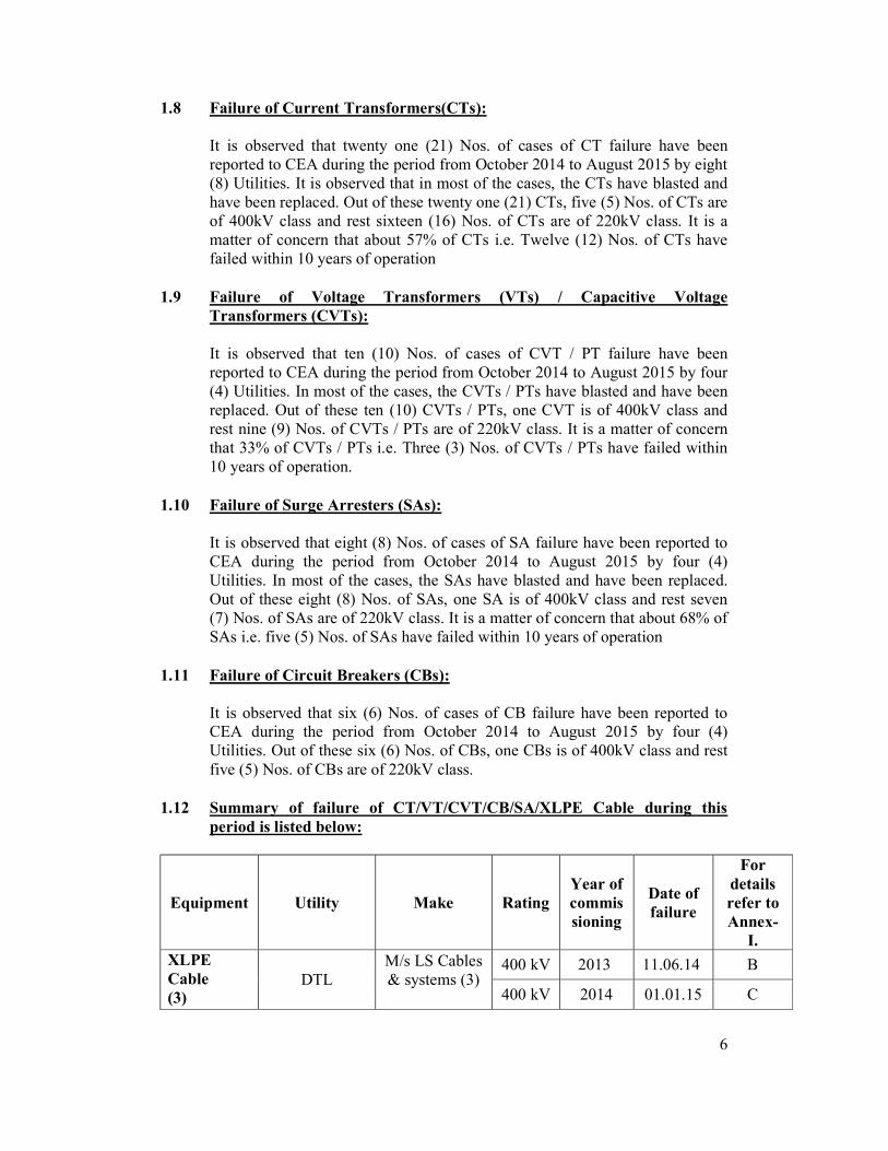
1.12 Summary of failure of CT/VT/CVT/CB/SA/XLPE Cable during this period is listed below:
Equipment Utility Make Rating Year of commissioning
Date of failure
For details refer to Annex-
I. XLPE Cable (3) DTL
M/s LS Cables & systems (3)
400 kV 2013 11.06.14 B 400 kV 2014 01.01.15 C

7
400 kV 2013 16.03.15 D CT (21) TANTRANSCO TELK(1) 230 kV 1986 09.09.14 J
M/s SCT(1) 230 kV 2014 04.01.15 M
KPTCL Shree
Venkateshwara Electical
Industries Pvt Ltd.(1)
220 kV 2006 21.08.14 P
MPPTCL SCT(6)
220 kV 2012 29.03.14 R
220 kV 2014 04.05.14 S 220 kV 2012 02.05.14 T 220 kV 2011 11.06.14 U 220 kV 2006 27.04.14 V 220 kV 2005 22.05.10 Z
Alstom(1) 220 kV 2011 30.01.14 W WS
Industries(1) 220 kV 2007 30.09.14 Y MPGENCO TELK(1) 400 kV 1983 11.02.15 AA
APPGCL TELK(1) 245 kV 1979 10.08.14 BB
BBMB ABB(2) 420 kV 2015 05.02.15 KK
420 kV 2015 07.02.15 KK WSI(1) 420 kV 1995 05.02.15 KK
BHEL(1) 400 kV 2002 02.03.15 LL TELK(1) 245 kV 1990 09.03.15 NN
APTRANSCO BHEL(1) 220 kV NA 12.10.14 RR WSI Ltd.(1) 220 kV NA 18.10.14 SS
NPCIL TELK(1) 220 kV 1993 11.03.15 F CVT (9)
TANTRANSCO CGL (4)
230 kV 1998 15.10.14 I 245 kV 1998 04.10.14 K 230 kV 2003 25.04.15 N 230 kV 2000 01.04.15 O
MPPTCL Alstom (1) 220 kV 2004 08.08.14 X BBMB BHEL (1) 400 kV 2013 24.12.14 JJ

8
WSI Ltd. (1) 245 kV 1990 09.03.15 NN CGL (1) 245 kV 2007 01.04.15 OO
GETCO CGL (1) 220 kV 2001 20.03.15 VV PT (1) GETCO BHEL (1) 220 kV 1996 07.06.15 WW LA (8) TANTRANSCO CGL (1) 230 kV 2001 15.11.14 L
BBMB
CGL (2)
198 kV 2006 27.10.14 FF 198 kV 2006 15.02.15 II
ELPRO (2)
198 kV 2000 08.03.15 MM 198 kV 1985 15.05.15 PP
OBLUM (1) 245 kV 2010 09.03.15 NN APTRANSCO CGL (1) 400 kV 2012 12.11.14 TT
GETCO LAMCO (1) 220 kV 2013 24.06.15 XX CB (6) PGCIL SIEMENS(1) 400 kV,
3000 A 2014 23.02.15 UU KSEB TELK(1) 220 kV 1999 28.04.15 G
APTRANSCO CGL(1) 220 kV NA 30.10.14 QQ
BBMB SIEMENS(2) 245 kV, NA 19.10.14 DD 245 kV NA 15.05.15 EE
CGL(1) 255 kV 2002 25.12.14 HH Note: Quantity in brackets indicates number of failed equipment. 2.0 OBSERVATIONS: (i) It is observed that reported failures are primarily due to following reasons:
a. Normal Ageing b. Frequent System Faults and transient over voltages generated by the
system. c. Failure of Insulation system (For CB/CT/PT/CVT/SA) d. Failure of Insulation system, Bushing & OLTC (For Transformers) e. Lack of good maintenance practice f. Failure of joints & terminations (For EHV XLPE Cables)
(ii) Condition Based Maintenance (CBM) Practices using modern diagnostic tools is not being followed by most of the utilities and in general, periodic Time Based Maintenance (TBM) is still being practised.

9
(iii) Adequate modern Diagnostic tools are not available with most of the State Utilities.
(iv) Most of the utilities are facing problem due to shortage of supporting staff for operation & maintenance of sub-station equipment. Sometimes Interpretation of test results becomes difficult in absence of experts / experienced O&M staffs.
(v) Sometimes due to unavailability of shut down, maintenance of equipment is deferred which affects the efficient functioning of the equipment and further deteriorate the health of equipment.
3.0 RECOMMENDATIONS: Some recommended measures suggested by the Committee for the Utilities to improve the performance of the substation equipment are listed below:
3.1 General Recommendations: (i) Original Equipment Manufacturer (OEM) should be consulted to discuss
about the cause of failure. (ii) The practice of Condition Based Monitoring using modern diagnostic tools
should be followed instead of conventional Periodic / Time Based Maintenance. Some of the important diagnostic tools have also been suggested in Central Electricity Authority (Technical Standards for Construction of Electrical Plants and Electric Lines) Regulations, 2010.
(iii) The frequency/periodicity of measurement should be changed depending on condition/healthiness of equipment in operation. The trend of the test results should be monitored rather than absolute values of test result.
(iv) Utilities should follow best practices for maintenance of each equipment. All the equipment which have reached/approaching end of service life need to be monitored closely and utility should plan and take action in advance for replacement of such equipment in a phased manner.
(v) The utilities should make it a practice to carry out various tests on major electrical equipment at sites one or two months prior to expiry of warranty period of respective equipment so that any abnormality observed in test results can be discussed with OEM for taking up further necessary action within warranty period.
(vi) The manufacturer’s recommendation for storage should be followed strictly in case of inordinate delay in commissioning of equipment as well as for long storage of equipment as spares.
(vii) Most of the utilities are facing problem due to shortage of supporting staff for operation & maintenance of sub-station equipment. The manpower should be strengthened for efficient operation & maintenance.
(viii) The regular cleaning of dust deposited on the housings of major equipment and bushings of transformer in Thermal Power Plant are essential to avoid flash over across the insulators. As such frequent flashover across the bushing

10
/ housing of equipment (due to operation in such dusty environment) may lead to failure of equipment. As an alternative to regular cleaning, the porcelain housings of major equipment (CB/LA/CT/CVT) and bushings of transformer may be protected by providing Room Temperature Vulcanisation (RTV) coating. RTV coating over porcelain housing of equipment (CB/LA/CT/CVT) / bushings of transformer & reactors may also be considered by utilities for substation equipment installed in pollution prone areas as an alternative to Polymer housed equipment.
(ix) Utilities should create and maintain complete data base of equipment/transformers including previous test reports (reports of factory tests/pre-commissioning tests/tests during O&M etc.), operation & maintenance history of equipment with make, model & year of commissioning etc. for proper evaluation, interpretation of test results and for taking Run-Refurbish-Replacement decision.
3.2 Recommendations for Transformers (ICT & GT) and Instrument Transformers (CT/PT/CVT):
(i) OLTC is one of the contributors to the failure of transformer. Possibility of eliminating OLTC from 400kV & 765kV class transformer should be considered (based on system studies) in consultation with Regional Power Committee (RPC) and Regional Load Dispatch Centre (RLDC) / POSOCO and CEA. The reduction in number of steps can also be considered in case of OLTC of 220kV and below voltage class transformers. The removal of OLTC will simplify the design and manufacturing of transformers.
(ii) Whenever there is movement of transformer either from manufacturing works or from one station to other, SFRA should be carried out before movement and after shifting to new location. SFRA signature would provide valuable information about deformation in winding /core during transportation.
(iii) Oil sampling for transformer oil testing should be done as per relevant IS/IEC. The oil sample should be tested in NABL accredited laboratory on calibrated equipment. Apart from monitoring absolute values of key parameters, trend of change in key values should also be closely monitored. In case of suspicious test results, second sample should also be got tested to ensure efficacy of test results.
(iv) The proper handling, loading, unloading, and storage at site before assembling play important role in satisfactory operation of equipment / transformer. Moreover, the erection of major equipment including transformers should always be carried out by experienced technical team under the close supervision of manufacturer. Inordinate delay in commissioning of equipment /transformer after reaching at site should be avoided. When there is a wide gap between the year of manufacturing and year of commission of the transformers, proper care must be taken to ensure satisfactory operation of transformer: a. Storage of transformer should be done as per manufacturer’s
recommendations.

11
b. Transformer should not be kept for more than three (3) months with inert gas (Nitrogen) filling and all throughout the period, required pressure needs to be maintained in order to avoid the exposure of active part to atmosphere.
c. After three (3) months, transformer should be filled with oil under vacuum and transformer should be provided with oil conservator including oil level indicator and breather. The oil parameters need to be monitored regularly.
(v) Tertiary winding should be avoided, wherever feasible, as it increases the probability of failure of the transformer. Transformer banks (formed out of single phase units) and 5 limbed 3 phase units should only be provided with tertiary winding of rating one third of HV rating. Tertiary terminals of transformer prone to short circuiting by external element such as bird or animal may be suitably insulated.
(vi) Periodic oil testing including DGA (wherever feasible) in case of instrument transformers are recommended. Health of gaskets and bellows needs to be checked periodically for CTs. Thermo vision scanning of CTs, CVTs and PTs should also be carried out regularly as a good maintenance practice.
(vii) While measuring tan delta of transformer bushing/CT/PT/CVT, apart from absolute value, rate of rise of tan delta should also be monitored and it should not be more than 0.1% per year. Frequency of measurement should be increased in case tan delta value is approaching 0.7%. Following tables can be referred while measuring tan δ and capacitance of CVTs:
Change in Tan
Monitoring Frequency Upto +0.002 Three yearly +0.002 to +0.003 Yearly Above +0.003 Alarming
Change in Capacitance Monitoring Frequency upto ±2% Three yearly ±2% to ±3% Yearly Above ±6% Alarming (Source: - CBIP Manual on EHV Substation Equipment Maintenance)
(viii) The change in secondary voltage of CVTs is a very good indicator of the condition/health of CVTs. Following table may be referred for monitoring of secondary voltage:
Drift in secondary Voltage (to be measured by 0.2 / 0.5 class multimeter)
Condition Monitoring Frequency
Upto ± 0.5 volts Healthy Six monthly

12
± 0.5 to ±0.8 volts To be monitored 03monthly ±0.8 to ±1.2 volts Close monitoring Monthly ±1.2 to ±2.0 volts Close monitoring 15 days above +2.0 volts Alarming replacement -0.8 to -4.0 volts Close monitoring 15 days less than -4.0 volts Alarming replacement
(Source: - CBIP Manual on EHV Substation Equipment Maintenance) (ix) Following table can be referred while measuring tan δ of CTs:
Value of Tan
Monitoring Frequency Upto 0.007 (annual [email protected]) Yearly
0.007 to 0.011 Half Yearly Above 0.011 Replace the CT (Source: - CBIP Manual on EHV Substation Equipment Maintenance)
(x) The capacitance and tan delta measurement of transformer bushing at variable frequency and DGA of bushing oil should be carried out for health assessment of bushings as this has been proved to be very effective in assessing the condition of in-service bushings.
3.3 Recommendations for Surge Arrester: Measurement of the 3rd harmonic resistive component of leakage current is a very good method for assessing healthiness of SA, which can be done on-line. If 3rd harmonic component of resistive current is more than 150 µA, then Insulation Resistance (IR) value test should also be conducted and if current exceeds 350 µA, then SA should be removed from service and replaced. The measurement of leakage current before and after the monsoon should be carried out so as to ascertain the effect of moisture. The specification of SA should include Sealing Test of SA which can be carried out at manufacturer’s works to ensure proper sealing against ingress of moisture.
3.4 Recommendations for Circuit Breaker: Dynamic Contact Resistance Measurement (DCRM) test kit is a very important tool to assess the healthiness of circuit breaker. This test may be carried out once in two years. Moreover, while formulating the specification for procurement of CB for new substation, provision for procurement of Operational Analyzer along with Dynamic Contact Resistance Measurement (DCRM) test kit should be included for one substation or a group of nearby substations depending upon the requirement.
3.5 Recommendations for XLPE Cables: (i) The earthing in respect of cable terminations & cross bonding arrangement
needs to be rechecked to ensure safe operation of cable.

13
(ii) The monitoring of healthiness of Sheath Voltage Limiter (SVL) and monitoring of Partial Discharge (PD) of all straight through joints & terminations is essential.
(iii) Distributed Temperature Sensors should be installed along the length of cable for monitoring of hot spot temperature of cable and joints.
*********************************************************************

14
ANNEXURE-I Detailed information in respect of each failed equipment reported to CEA between 1st October 2014 and 31st August 2015 and brief analysis of failure of these equipment. A. Failure of 16.5/400kV, 220.6 MVA GT at 400 kV PPS-III Bawana of
Pragati Power Corporation Ltd (PPCL). 1 Name of Substation : 1500 MW CCPP Pragati-III,
Bawana
2 Utility/Owner of substation : Pragati Power Corporation Ltd. (PPCL)
3 Faulty Equipment : Generator Transformer (GT#3)
4 Rating : 16.5/ 400kV, 220.6 MVA
5 Make : BHEL
6 Sr. No. : 6006797
7 Year of manufacturing : 2009
8 Year of commissioning : 2012 (June 19th)
9 Date and time of occurrence/discovery of fault
: 24.03.2015 @ 04:47 hrs
10 Information received in CEA : 26.03.2015
11 Fault discovered during : Operation
12 Present condition of equipment
: Damaged
13 Details of previous maintenance
: DGA of the transformer oil was conducted on 06.02.2015 and results were found in order.
14 Details of previous failure : --
15 Sequence of events/ Description of failure :
GT#3 along with associated Steam Turbine Generator (STG#2) was running with generation of 220 MW and 108 MW respectively. On 24.03.15, at about

15
04:47 hrs, the machine tripped on transformer differential protection and overall differential protection followed by an explosion which was heard by the control room staff. Operation staff on duty immediately rushed to the site and found that the Generator Transformer of GTG #3 was on flames with two bushings (R&Y phase) dislocated from the transformer tank body and lying away from the transformer. CISF Fire Wing had taken action to douse the flames. Aqueous Film Forming (AFF) Foam was also used to blanket the fire and by 06:00 hrs, the fire was brought under control.
A team of officers from CEA alongwith officers of Pragati Power Corporation Limited (PPCL) visited the site of failure on 27.03.15. During the inspection, it was noticed that GT had completely burnt, middle portion of the tank had bulged out, opening in one location of the tank was clearly visible and some portion of the core had protruded outside the tank. All three HV side bushings were badly damaged and two of them were dislocated from the tank due to blast. R & Y-phase surge arresters (SA) provided for the protection of transformer were also damaged completely. Part of the bus duct on LV side and part of the piping of the emulsifier system had also damaged. PPCL informed that no internal inspection could be carried out either by PPCL or BHEL as the transformer was very hot and smoke was coming out. Transformer was very hot even at the time of visit to site and the transformer was so badly damaged that no tests could be carried out by PPCL after the failure. Even BDV & DGA of oil was not possible as all the oil had leaked out from the transformer tank. Apparently, the transformer seems to be in irreparable condition and complete replacement may be required.
16 Details of Tests done after failure : No test could be performed as GT was completely damaged.
17 Probable cause of failure :
It was reported that fault was cleared in three cycles i.e after 60msec and following protection relays had operated: a. Overall Differential Relay GTR3 b. Transformer Differential Relay GTR1 c. GTSPR , GTPRV, and GT buchholz relay. Operation of differential relay indicates internal fault in the transformer or the failure of bushing. The DR submitted by PPCL indicates high short circuit current flow of the order of 37kA in the winding and the photograph showing the condition winding supports the same. Because of flow of such high fault current, sudden pressure rise inside the tank due to fault gases might have led to explosion of the tank. The operation of buchholz relay, PRV and SPR devices further supports such a scenario. The sudden pressure rise inside the tank and condition of bushings after failure indicate failure of bushing might have led to failure of transformer.
16
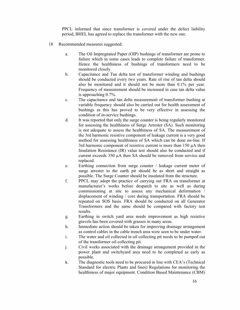
PPCL informed that since transformer is covered under the defect liability period, BHEL has agreed to replace the transformer with the new one.
18 Recommended measures suggested: a. The Oil Impregnated Paper (OIP) bushings of transformer are prone to
failure which in some cases leads to complete failure of transformer. Hence the healthiness of bushings of transformers need to be monitored closely.
b. Capacitance and Tan delta test of transformer winding and bushings should be conducted every two years. Rate of rise of tan delta should also be monitored and it should not be more than 0.1% per year. Frequency of measurement should be increased in case tan delta value is approaching 0.7%.
c. The capacitance and tan delta measurement of transformer bushing at variable frequency should also be carried out for health assessment of bushings as this has proved to be very effective in assessing the condition of in-service bushings.
d. It was reported that only the surge counter is being regularly monitored for assessing the healthiness of Surge Arrester (SA). Such monitoring is not adequate to assess the healthiness of SA. The measurement of the 3rd harmonic resistive component of leakage current is a very good method for assessing healthiness of SA which can be done on-line. If 3rd harmonic component of resistive current is more than 150 µA then Insulation Resistance (IR) value test should also be conducted and if current exceeds 350 µA then SA should be removed from service and replaced.
e. Earthing connection from surge counter / leakage current meter of surge arrester to the earth pit should be as short and straight as possible. The Surge Counter should be insulated from the structure.
f. PPCL may adopt the practice of carrying out FRA on transformer at manufacturer’s works before despatch to site as well as during commissioning at site to assess any mechanical deformation / displacement of winding / core during transportation. FRA should be repeated on SOS basis. FRA should be conducted on all Generator Transformers and the same should be compared with factory test results.
g. Earthing in switch yard area needs improvement as high resistive gravels has been covered with grasses in many areas.
h. Immediate action should be taken for improving drainage arrangement as control cables in the cable trench area were seen to be under water.
i. The water and oil collected in oil collecting pit needs to be pumped out of the transformer oil collecting pit.
j. Civil works associated with the drainage arrangement provided in the power plant and switchyard area need to be completed as early as possible.
k. The diagnostic tools need to be procured in line with CEA’s (Technical Standard for electric Plants and lines) Regulations for monitoring the healthiness of major equipment. Condition Based Maintenance (CBM)

17
practices should be adopted in place of periodic Time Based Maintenance. Frequency of various tests needs to be decided based on the condition of equipment and trend of the test results.
l. The regular cleaning of dust deposited the housings of major equipment and bushings of transformer is essential to avoid flash over across the insulators. As such frequent flashover across the bushing / housing of equipment (due to operation in such dusty environment) may lead to failure of equipment. As an alternative to regular cleaning, the housings of major equipment and bushings of transformer may be protected by providing Room Temperature Vulcanisation (RTV) coating.
m. The transformer seems to be in irreparable condition and complete replacement of transformer might be required
B. Failure of straight through joints of XLPE cable in 400kV Bamnauli-
Jhatikara Ckt-II of Delhi Transco Ltd. 1 Name of Substation : 400 kV Bamnauli Substation,
Delhi
2 Utility/Owner of substation : DTL
3 Faulty Equipment : Straight through joints of XLPE Cable (400kV Bamnauli-Jhatikara Ckt-II)
4 Rating : 400 kV
5 Make : M/s LS Cables & Systems
6 Sr. No. : --
7 Year of manufacturing : 2013
8 Year of commissioning : 2013
9 Date and time of occurrence/discovery of fault
: 11.06.14
10 Information received in CEA : 01.09.14
11 Fault discovered during : Operation
12 Present condition of equipment
: Joints replaced
13 Details of previous maintenance
: --
14 Details of previous failure : Nil

18
15 Sequence of events/ Description of failure
:
Hot spot was observed at bus isolator connection in Bamnauli S/s during thermal/infra red scanning. Accordingly both circuits of 400kV Bamnauli-Jhatikara line were taken under shut down to investigate and rectify the problem at jumper connection. The shut down was extended for about 4-5 hours to rectify the problem. While charging the 2nd circuit after rectification of jumper problem, the straight through joint in the cable trench had blasted. The joint in Y phase cable of the above circuit had caught fire and also damaged the nearby R & B phase cables. Second circuit was left unharmed. It was informed by DTL that there was no fire control mechanism in the sub-station. The fire tender arrived at the site after about five hours of the incidence and fire was brought under control. Bamnauli- Jhatikara ckt-II was restored with the help of Emergency Restoration Systems (ERS).
A team of officers from CEA alongwith officers of DTL, Pragati Power Corporation Limited (PPCL) and M/s LS Cable had visited the site of failure of straight through joints of cable circuit on 11-9-2014.
The power flow on cable prior to joint failure on 11-06-2014 was about 200-300MW. Similarly the power flow in the cable prior to blast of cable end termination on 01-01-2014 was about 350 MW. In both case, the load on cable was much less than rated current rating of the cable.
16 Details of Tests done after failure
: None
17 Observations :
During the visit it was observed that Distributed Temperature Sensor (DTS) with Fibre Optic Cable is running along one phase (in Y-Phase) of each circuit in order to monitor hot spot along the length of cable. However, as reported by the representative of Bamnauli substation, that most of the time DTS is out of service and is giving problem since its commissioning. The problem has not been rectified so far by M/s L.S. cable even after repeated requests. It was also observed that there was no provision to monitor hot spot temperature of terminations.
18 Probable cause of failure:
:
From available information it is difficult to pin point the reason of failure of joint of the cable. However, failure due to prolonged Partial Discharge (PD) cannot be ruled out.
19 Recommended measures suggested:
:

19
The problem in DTS system need to be rectified by M/s LS Cables in consultation with DTL/PPCL/BHEL and should be in place as soon as possible for monitoring of hot spot along the length of the cable. DTL should monitor hot spot regularly after rectification. The monitoring of healthiness of Sheath Voltage Limiter (SVL) and monitoring of Partial Discharge (PD) of all straight through joints & terminations in addition to hot spot monitoring using DTS is essential.
Surge arrester (SA) is a vital equipment for providing protection against switching & lighting over voltage. Hence monitoring the healthiness of SA is essential. Periodic condition monitoring of Metal Oxide Surge Arresters including measurement of 3rd harmonic resistive component of leakage current is recommended. If harmonic current is found to be more than 150 µA, measurement of insulation resistance should also be carried out. If the resistive component of leakage current exceeds 350 µA, SA should be replaced immediately.
The earthing in respect of cable terminations & cross bonding arrangement needs to be rechecked to ensure safe operation of cable. The healthiness of cable Sheath Voltage Limiter (SVL) may be checked.
C. Failure of cable end termination of XLPE cable in 400kV Bamnauli-
Ballabhgarh Ckt-II of Delhi Transco Ltd. 1 Name of Substation : 400 kV Bamnauli Substation, Delhi
2 Utility/Owner of substation : DTL
3 Faulty Equipment : Cable end termination of XLPE
Cable (400kV Bamnauli-Ballabhgarh Ckt-II)
4 Rating : 400 kV
5 Make : M/s LS Cables & Systems
6 Sr. No. : --
7 Year of manufacturing : 2013
8 Year of commissioning : 2014
9 Date and time of occurrence/discovery of fault
: 01.01.15 @17:31 hrs
10 Information received in CEA : 05.01.15
11 Fault discovered during : Operation
12 Present condition of equipment
: --

20
13 Details of previous maintenance
: --
14 Details of previous failure : Nil
15 Sequence of events/ Description of failure
:
On 01.01.15 at 17:31 hrs, a blast was reported at the cable end termination of one of the cables of ‘B’ phase of 400 kV Bamnauli-Ballabhgarh ckt-II in PPCL premises while the system was running under normal load. This blast completely damaged the cable termination porcelain housing and splinters from this housing in turn damaged some petticoats of nearby ‘B’ phase cable termination porcelain housing. The outer sheath of other cable of ‘B’ phase of circuit II also got burnt. Burnt portion of the damaged cable were cut and the cable end & damaged termination were sealed in plastic wrapping by M/s LS Cables to protect cable from ingress of water. Bamnauli- Ballabhgarh ckt-II was restored with the help of Emergency Restoration Systems (ERS).
A team of officers from CEA alongwith officers of DTL and Pragati Power Corporation Limited (PPCL) had visited the site of failure of cable end terminations of Bamnauli- Ballabhgarh ckt-II on 14.01.2015.
16 Details of Tests done after failure
: None
17 Observations :
During the visit it was observed that Distributed Temperature Sensor (DTS) with Fibre Optic Cable is running along one phase (in Y-Phase) of each circuit in order to monitor hot spot along the length of cable. However, as reported by the representative of Bamnauli substation, that most of the time DTS is out of service and is giving problem since its commissioning. The problem has not been rectified so far by M/s L.S. cable even after repeated requests. It was also observed that there was no provision to monitor hot spot temperature of terminations.
18 Probable cause of failure
:
From available information it is difficult to pin point the reason of failure of termination of the cable. However, failure due to prolonged Partial Discharge (PD) cannot be ruled out.
19 Recommended measures suggested :
The problem in DTS system need to be rectified by M/s LS Cables in consultation with DTL/PPCL/BHEL and should be in place as soon as possible for monitoring of hot spot along the length of the cable. DTL should monitor hot spot regularly after rectification. The monitoring of healthiness of Sheath

21
Voltage Limiter (SVL) and monitoring of Partial Discharge (PD) of all straight through joints & terminations in addition to hot spot monitoring using DTS is essential.
Surge arrester (SA) is a vital equipment for providing protection against switching & lighting over voltage. Hence monitoring the healthiness of SA is essential. Periodic condition monitoring of Metal Oxide Surge Arresters including measurement of 3rd harmonic resistive component of leakage current is recommended. If harmonic current is found to be more than 150 µA, measurement of insulation resistance should also be carried out. If the resistive component of leakage current exceeds 350 µA, SA should be replaced immediately.
The earthing in respect of cable terminations & cross bonding arrangement needs to be rechecked to ensure safe operation of cable. The healthiness of cable Sheath Voltage Limiter (SVL) may be checked.
D. Failure of cable joints of of XLPE cable in 400kV Bamnauli-Jhatikara
Ckt-I of Delhi Transco Ltd. 1 Name of Substation : 400 kV Bamnauli
Substation, Delhi
2 Utility/Owner of substation : DTL
3 Faulty Equipment : Cable joints of XLPE Cable (400kV Bamnauli-Jhatikara Ckt-I)
4 Rating : 400 kV
5 Make : M/s LS Cables & Systems
6 Sr. No. : --
7 Year of manufacturing : 2013
8 Year of commissioning : 2013
9 Date and time of occurrence/discovery of fault
: 16.03.15@19:43hrs
10 Information received in CEA : 19.03.15
11 Fault discovered during : Operation
12 Present condition of equipment
: --
13 Details of previous maintenance : --
22
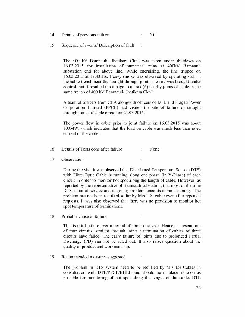
14 Details of previous failure : Nil
15 Sequence of events/ Description of fault :
The 400 kV Bamnauli- Jhatikara Ckt-I was taken under shutdown on 16.03.2015 for installation of numerical relay at 400kV Bamnauli substation end for above line. While energising, the line tripped on 16.03.2015 at 19:43Hrs. Heavy smoke was observed by operating staff in the cable trench near the straight through joint. The fire was brought under control, but it resulted in damage to all six (6) nearby joints of cable in the same trench of 400 kV Bamnauli- Jhatikara Ckt-I.
A team of officers from CEA alongwith officers of DTL and Pragati Power Corporation Limited (PPCL) had visited the site of failure of straight through joints of cable circuit on 23.03.2015. The power flow in cable prior to joint failure on 16.03.2015 was about 100MW, which indicates that the load on cable was much less than rated current of the cable.
16 Details of Tests done after failure
: None
17 Observations :
During the visit it was observed that Distributed Temperature Sensor (DTS) with Fibre Optic Cable is running along one phase (in Y-Phase) of each circuit in order to monitor hot spot along the length of cable. However, as reported by the representative of Bamnauli substation, that most of the time DTS is out of service and is giving problem since its commissioning. The problem has not been rectified so far by M/s L.S. cable even after repeated requests. It was also observed that there was no provision to monitor hot spot temperature of terminations.
18 Probable cause of failure :
This is third failure over a period of about one year. Hence at present, out of four circuits, straight through joints / termination of cables of three circuits have failed. The early failure of joints due to prolonged Partial Discharge (PD) can not be ruled out. It also raises question about the quality of product and workmanship.
19 Recommended measures suggested :
The problem in DTS system need to be rectified by M/s LS Cables in consultation with DTL/PPCL/BHEL and should be in place as soon as possible for monitoring of hot spot along the length of the cable. DTL

23
should monitor hot spot regularly after rectification. The monitoring of healthiness of Sheath Voltage Limiter (SVL) and monitoring of Partial Discharge (PD) of all straight through joints & terminations in addition to hot spot monitoring using DTS is essential.
Surge arrester (SA) is vital equipment for providing protection against switching & lighting over voltage. Hence monitoring the healthiness of SA is essential. Periodic condition monitoring of Metal Oxide Surge Arresters including measurement of 3rd harmonic resistive component of leakage current is recommended. If harmonic current is found to be more than 150 µA, measurement of insulation resistance should also be carried out. If the resistive component of leakage current exceeds 350 µA, SA should be replaced immediately.
The earthing in respect of cable terminations & cross bonding arrangement needs to be rechecked to ensure safe operation of cable.
Since three major failures have taken place just before completion of defect liability period i.e. within one year of commissioning, it a matter of serious concern. The close monitoring of cable system was required and the supplier, M/s BHEL / M/s LS cable have not taken remedial measures to avoid such failure. Hence a meeting may be arranged by DTL / PPCL, with the technical experts of LS cable, DTL, PPCL, BHEL and CEA, to discuss about the future course of action as it was brought to notice that defect liability period is already over. Matter may also be taken up with management of M/s LS cable to review for extension of the defect liability period considering the rate of failure and normal operation of the cable system can be observed over the extended period.
E. Failure of 207 MVA, 21/400 kV Generator Transformer ‘Y’ phase at 400
kV Bellari Thermal Power Station of KPCL. 1 Name of Substation : 400 kV Bellari Thermal Power Station
(2x500 MW)
2 Utility/Owner of substation : KPCL
3 Faulty Equipment : Generator Transformer (Y phase Unit 1)
4 Rating : 207 MVA, 21/400 kV
5 Make : BHEL
6 Sr. No. : 6006203
7 Year of manufacturing : 2006
8 Year of commissioning : 2007

24
9 Date and time of occurrence/discovery of fault
: 06.04.2015 @ 14:06 hrs
10 Information received in CEA : 17.04.2015
11 Fault discovered during : Operation
12 Present condition of equipment
: Faulty GT is being replaced with spare GT.
13 Details of previous maintenance
: Following works were carried out during Annual OH in Aug, 2013: a. Oil filtration b. BDV checking c. Checking of healthiness of temperature indicators. d. Checking of healthiness of level indicators. e. Checking of transformer protection/ annunciation circuits f. Checking of healthiness of radiator fan/pump circuits. g. Periodic oil testing by CPRI in February 2015. CPRI had recommended monitoring of oil after six months as value of Ethylene gas in the oil was found to be 69 ppm which is on higher side.
14 Details of previous failure : One more failure had occurred in May 2014 in B phase of Unit-I. During that time only HV bushing had failed and the complete transformer was perfectly healthy.
15 Sequence of events/ Description of failure
:
On 06.04.2015, Unit-1 was in running condition at 470MW @ 14.06 hrs, large sound was heard and the HV bushing along with its turret blasted and fallen down on the ground. Major damage was also observed on the main tank, its rim was deformed, stiffeners cracked and tank was also found bulged. LV side turret, bus duct and bellows were also found damaged. Common marshalling kiosk and lightning arrestors were also burnt.
Unit-1 Tripped on class ‘A’ protection as detailed below:
1.1 Group -2: 87OAR Static relay (Gen & GT(R ph) OA diff protn) optd. 1.2 Group -2: 87OAY Static relay (Gen & GT(Y ph) OA diff protn) optd.

25
1.3 Group -2: 87OAX Electro-mech relay Aux to 87OA OA diff Protn optd.
1.4 Group -2: 87HV Electro-mech relay GT HV& Overhead connection diff(only Y-ph) optd.
1.5 Group -2: 30GTE -Electro-mech relay GT Sudden Pressure (R-Y-B ph) optd.
1.6 Group -2: 30GTC -Electro-mech relay GT Buch trip (R-Y-B ph) optd. 1.7 Group -2: 30GTH - Electro-mech relay GT Pressure Relief Device-
B(R-Y-B ph) optd. 1.8 Group -1: 30GTP Electro-mech relay GT PRV-A (R-Y-B ph) optd. 1.9 286A, 286AX, 286AY optd. 1.10 186A, 186AX, 186AYoptd. 1.11 Gen Main HV Circuit Breaker open 1.12 Gen Middle HV Circuit Breaker open 1.13 FCB open 1.14 Turbine tripped 1.15 286TU optd. 1.16 286C, 286CX optd. 1.17 186C, 186CX optd. 1.18 Group -1: GR 1 numerical Relay LEDs : 100%/95% SEF & Dead M/c
Protn optd. 1.19 286B, 186B optd. 1.20 Group-1: 87/51NGT numerical Relay LEDs : R-ph Diff, Y-ph Diff, B-
ph Diff, 1>Pickedup (Over current) protn optd. 1.21 Group-2 : 30GTAR – Electro-mech relay GT HV WTI R-ph very
high optd. 1.22 Group-2 : 30GTAY – Electro-mech relay GT HV WTI Y-ph very
high optd. 1.23 Group-2 : 30GTAB – Electro-mech relay GT HV WTI B-ph very
high optd. 1.24 Group-2 : 30GTBR – Electro-mech relay GT LV WTI R-ph very
high optd. 1.25 Group-2 : 30GTBY – Electro-mech relay GT LV WTI Y-ph very
high optd. 1.26 Group-2 : 30GTBB – Electro-mech relay GT LV WTI B-ph very high
optd. 1.27 Group-2 : 30GTJR – Electro-mech relay GT OT1 R-ph very high
optd. 1.28 Group-2 : 30GTJY – Electro-mech relay GT OT1 Y-ph very high
optd. 1.29 Group-2 : 30GTJB – Electro-mech relay GT OT1 B-ph very high
optd. 1.30 Group-2 : 64GIT – Electro-mech relay Generator Interterm fault
protection optd. 1.31 Group-2 : 64G3 – Electro-mech relay Generator 95% Stator SEF
protection optd. 1.32 Group-2 : 64G3 – Electro-mech relay Generator 95% Stator SEF
protection optd. A team of experts from BHEL Bhopal and PSTS Noida inspected the site and
26
observed following points during internal inspection of GT: i). Lot of burnt carbon particles and debris were found inside the tank near the failure zone of HV turret and bushing. ii). Active parts of core and winding were comparatively clean and did not indicate any signs of internal failure inside winding assembly. iii). The zone near bushing bottom shield and bottom bushing insulation contained many pitting and arcing marks on tank wall. iv). The bushing oil end shield was found completely damaged and very big holes were found on its surface due to huge arcing during the failure incident.
The team in its report indicated that failure initiated from the bottom part of HV bushing in the vicinity of lower shield. However, the exact cause of failure cannot be ascertained due to extensive damage, fire and lack of data recording at the failure instance.
16 Details of Tests done after
failure : Magnetizing Current measurement was
done and it did not indicate any inter turn fault winding. Ratio test inferred healthiness of winding assembly.
17 Probable cause of failure :
The analysis by BHEL & PSTS team indicates possibility of fault initiation near HV bushing lower end zone, however due to the extensive damage and lack of data/records at the failure instance, it cannot be ascertained with certainty whether it failed due to thermal/dielectric runaway inside the bushing or due to any abnormality in its vicinity like oil etc or overstressing due to system. During periodic oil testing by CPRI in February 2015, ethylene was found to be on higher side and it was suggested by CPRI to monitor oil of GT every six month, however, GT failed after two months of carrying oil test. Magnetizing Current measurement and Ratio test carried out on GT after failure did not indicate any problem in winding assembly.
F. Failure of 220 kV CT (B phase) in 220 kV Kaiga Kodasalli line at 220 kV
Kaiga switchyard of NPCIL. 1 Name of Substation : 220 kV Kaiga switchyard
2 Utility/Owner of substation : NPCIL
3 Faulty Equipment : CT (B phase of Kaiga-Kodasalli line)
4 Rating : 220 kV
5 Make : TELK
6 Sr. No. : 230182-21

27
7 Year of manufacturing : 1993
8 Year of commissioning : 1993
9 Date and time of
occurrence/discovery of fault : 11.03.2015 @ 21:59 hrs
10 Information received in CEA : 22.04.2015
11 Fault discovered during : Operation
12 Present condition of equipment
: Faulty CT was replaced and line was put into service on 15.03.15.
13 Details of previous maintenance
: Regular checks like terminal tightness and insulator cleaning were being done biennially and checks like oil level monitoring, thermography on power connections were being done on monthly basis. The previous checks done during January, 2015 (biennial) and February, 2015 (monthly) did not indicate any degradation of CT.
14 Details of previous failure : --
15 Sequence of events/ Description of failure
:
On 11.03.2015, KGS-1&2 were operating at 100% FP. 220 kV buses 1 & 2 were in service. 220 kV line-1, ICT-2, GT-2, SUT-1 and SUT-4 were connected to Main Bus-1 and 220 kV line-2, ICT-1, GT-1, SUT-2 and SUT-3 were connected to Main Bus-2. At 21:59:15 hrs, the B phase CT of 220 kV line 2 (Kaiga-Kodasalli) connected to Main Bus-II failed and caused 220 kV Bus-II bus bar differential protection to actuate. This resulted in tripping of all breakers connected to 220 kV Bus-2.
16 Details of Tests done after failure
: No test could be performed as CT was completely damaged.
17 Probable cause of failure :
No test could be performed as CT was completely damaged. CT had served for 22 years. Ageing might be a reason of failure.

28
G. Failure of R phase limb of 220 kV Circuit Breaker of Generator U#3 at 220 kV Moolamattom switchyard of KSEB.
1 Name of Substation : 220 kV Switchyard, Moolamattom
2 Utility/Owner of substation : KSEB
3 Faulty Equipment : R phase limb of Circuit Breaker of Generator U#3
4 Rating : 220 kV
5 Make : TELK
6 Sr. No. : 860043/1
7 Year of manufacturing : 1998
8 Year of commissioning : 1999
9 Date and time of occurrence/discovery of fault
: 28.04.2015 @ 12:30 hrs
10 Information received in CEA : 26.05.2015
11 Fault discovered during : Operation
12 Present condition of equipment
: R & Y phase limb of circuit breaker of Generator U#3 were replaced.
13 Details of previous maintenance
: Routine maintenance, Monthly maintenance and Annual maintenance as per fixed pattern based on manufacturer recommendations, IS codes, various statutes and practical experience was carried out. Last maintenance date and specific details of tests have not been provided.
14 Details of previous failure : Nil
15 Sequence of events/ Description of failure
:
The generator unit#3 of Idukki HEP was synchronized to the grid at 12:19 hrs on 28.04.2015 and the generation was increased by the operator from the control room. The shift staff at switch yard had returned to the control room and at 12:30 hrs, the R phase limb of the circuit breaker associated with this generator exploded resulting in total supply failure. At that time generator

29
units # 1, 2, 4, 5 and 6 and 220 kV feeders IDUD, IDNE, IDKL-1, IDKL-2, IDLP-1, IDLP-2 and 50 MVA, 220/66 kV transformer were in service. On immediate inspection, it was seen that the possible reason of failure could be the inadequate making of breaker main contacts inside the interrupting chamber assembly leading to localized overheating and subsequent thermal breakdown. This might have occurred due to the continued stress on the breaker subsequent to increased lightening, associated with pre monsoon showers.
16 Details of Tests done after failure
: None as R phase limb was completely damaged.
17 Probable cause of failure :
The breakers at Idukki HEP are subjected to number of operations as generating units are switched off and on at least once every day. Also the location of switchyard is more prone to lightening which makes the situation more vulnerable along with aging of equipment. Breaker was in operation for 16 years. R & Y phase limb of circuit breaker of Generator U#3 were replaced.
H. Failure of 100 MVA, 220/66-33/11 kV Power Transformer at 220 kV Park
Street sub-station of Delhi Transco Ltd. 1 Name of Substation : 220 kV Park Street substation
(Total capacity: 4x100 MVA, 220/66/33 kV+2x30 MVA, 66/33 kV)
2 Utility/Owner of substation : DTL
3 Faulty Equipment : Power Transformer
4 Rating : 100 MVA, 220/66-33/11 kV
5 Make : BHEL
6 Sr. No. : 2008098
7 Year of manufacturing : 1994
8 Year of commissioning : 1994 (June 11th)
9 Date and time of occurrence/discovery of fault
: 07.09.2014 @ 16:34 hrs
10 Information received in CEA : 28.11.2014
11 Fault discovered during : Operation

30
12 Present condition of equipment
: Faulty transformer dismantled and new Transformer installed.
13 Details of previous maintenance
: Transformer oil test in CPRI on 19.03.2014 Thermo vision scanning on 04.06.14 DGA of oil on 08.07.14 All LV tests (magnetizing current, magnetic balance, winding resistance,
voltage ratio, insulation resistance) and tan delta & capacitance measurement of winding and bushings on 29.08.14 & 31.08.14. Tan delta of 66 kV Y-phase bushing was found to be abnormal and the same was replaced with new bushing on 31.08.14.
14 Details of previous failure : Nil
15 Sequence of events/ Description of
failure :
On 07.09.2014 at 16:34 hrs, the transformer tripped with following relay indications: Buchholz alarm Differential relays (87 Ta and Tc)
The load on transformer at 1600 hrs was 23 MW.
16 Details of Tests done after failure :
Following tests were carried out on the damaged equipment: 1. Winding resistance 2. Magnetizing balance 3. Magnetizing current 4. IR value 5. Tan delta 6. SFRA 7. DGA
17 Observations :
It was observed that results of SFRA, magnetizing balance and exciting current tests were not showing the normal trends. The DGA testing also showed the presence of Acetylene gas at 14.2 ppm. OEM M/s BHEL inspected the transformer on 13.09.14 and observed that some Perma wood insulation pieces between core and end frame & core and coil packing were dislocated. No pitting or burning marks were observed in any lead of windings or in OLTC. M/s BHEL also stated that the transformer was reparable at BHEL’s workshop but not at site. The damaged transformer was dismantled and new transformer

31
was commissioned in its place. 18 Probable cause of failure :
Operation of buchholz alarm & differential relay and increase of Acetylene from <0.5 ppm to 14.2 ppm within 9 days indicate towards internal fault in the transformer which is also proved by abnormal results of SFRA, magnetizing balance and exciting current tests.
I. Failure of 230 kV Y phase Capacitor Voltage Transformer (CVT) in line
side of 230 kV Cuddalore-TAQA Neyveli feeder at 230 kV Cuddalore substation of Tamil Nadu Transmission Corporation Ltd. (TANTRANSCO)
1 Name of Substation : 230 kV Cuddalore substation
2 Utility/Owner of substation : TANTRANSCO
3 Faulty Equipment : CVT (Y phase)
4 Rating : 230 kV
5 Make : M/s Crompton Greaves
6 Sr. No. : 9687
7 Year of manufacturing : 1997
8 Year of commissioning : --
9 Date and time of occurrence/discovery of fault
: 15.10.2014 @ 10:45 hrs
10 Information received in CEA : 27.10.2014
11 Fault discovered during : Operation
12 Present condition of equipment
: Not reparable, proposed to be replaced
13 Details of previous maintenance
: --
14 Details of previous failure : --
15 Sequence of events/ Description of failure
:
On 15.10.2014 at 10:45 hrs. in 230 kV Cuddalore-TAQA Neyveli feeder line

32
side ‘Y’ phase CVT, heavy sound and arc on the CVT was noticed. On inspection, the CVT was found to be totally damaged. Weather condition was reported as heavy rain, lightening and thunder. The condition of battery, relays and trip circuit was found OK.
16 Details of Tests done after failure
: No tests conducted as CVT was totally damaged.
17 Observations and Probable cause of failure
: --
CVT had completely damaged with heavy sound and arc. After failure, it was not possible to conduct any test on it. Sufficient information is not available to draw any conclusion about probable cause of failure of CVT.
J. Failure of B phase CT in 230 kV Trichy-Alundur II feeder at 230 kV Trichy substation of TANTRANSCO
1 Name of Substation : 230 kV Trichy substation
2 Utility/Owner of substation : TANTRANSCO
3 Faulty Equipment : CT (B phase)
4 Rating : 230 kV
5 Make : TELK
6 Sr. No. : B-230116-23
7 Year of manufacturing : --
8 Year of commissioning : 1986 (29th March)
9 Date and time of occurrence/discovery of fault
: 09.09.2014 @ 21:40 hrs
10 Information received in CEA : 31.10.2014
11 Fault discovered during : Operation
12 Present condition of equipment
: Replaced with new CT on 11.09.2014
13 Details of previous maintenance
: --
14 Details of previous failure : --
33
15 Sequence of events/ Description of failure
:
On 09.09.2014 at 21:40 hrs, B phase CT of Cuddalore-TAQA Neyveli feeder suddenly burst out and oil spurt out with fire surrounding it and the porcelain petty coat broken into pieces. Following events took place: 1. Busbar protection operated 2. Master relays of Auto transformer I & II operated 3. 230 kV feeders Alundur I, Alundur II, Samayapuram breakers tripped at both end. 4. 230 kV Trichy-Perambalur breaker tripped at Trichy SS. 5. 230 kV HV I, HV II breakers tripped 6. 110 kV LV I and LV II breakers tripped and LV III breaker hand tripped
16 Details of Tests done after failure
: None
17 Probable cause of failure :
CT had failed which resulted in operation of busbar protection and tripping of Auto-transformers and 220 kV feeders. Since CT had damaged, no test could be conducted after failure. The CT has served for around 29 years. Ageing might be one of the reasons of failure. Failed CT was replaced with new CT.
K. Failure of 230 kV Y phase CVT in Bus ‘B’ at 230 kV Cuddalore substation
of TANTRANSCO 1 Name of Substation : 230 kV Cuddalore substation
2 Utility/Owner of substation : TANTRANSCO
3 Faulty Equipment : CVT (Y phase)
4 Rating : 245 kV
5 Make : M/s Crompton Greaves
6 Sr. No. : 8475
7 Year of manufacturing : 1995
8 Year of commissioning : --
9 Date and time of
occurrence/discovery of fault : 04.10.2014 @ 18:00 hrs
10 Information received in CEA : 17.11.2014

34
11 Fault discovered during : Operation
12 Present condition of equipment
: Not reparable, proposed to be replaced
13 Details of previous maintenance
: --
14 Details of previous failure : --
15 Sequence of events/ Description of failure
:
On 04.10.2014 at 18:00 hrs CVT failed. Condition of battery, relays and trip circuit was found OK.
16 Details of Tests done after failure
: Secondary voltage measured after failure was found to be RN – 63.4 V, YN – 34.0 V & BN – 63.4 V. The secondary voltage YN was found to be very low. Different megger values measured were: 1. Primary to Earth – 50k MΩ 2. Protection Core
I. Primary to Secondary – 100k MΩ
II. Secondary to Earth – 1k MΩ
3. Metering Core I. Primary to Secondary -
0.5k MΩ II. Secondary to Earth – 1k
MΩ 4. Protection Core to Metering Core – 0.5k MΩ
17 Observations & Probable cause of failure
:
Secondary voltage of Y phase CVT was found to be 34 V which is very less than normal value of 63.5 V. This indicates failure of capacitor elements. CVT was irreparable and was proposed to be replaced with healthy CVT.
L. Failure of Y phase 230 kV LA of Auto transformer at 230 kV
Kadalangudy substation of TANTRANSCO 1 Name of Substation : 230 kV Kadalangudy substation

35
2 Utility/Owner of substation : TANTRANSCO
3 Faulty Equipment : LA (Y phase) 4 Rating : 230 kV
5 Make : M/s Crompton Greaves
6 Sr. No. : 4894
7 Year of manufacturing : --
8 Year of commissioning : --
9 Date and time of
occurrence/discovery of fault : 15.11.2014 @ 16:00 hrs
10 Information received in CEA : 09.01.2015
11 Fault discovered during : Operation
12 Present condition of equipment
: Replaced
13 Details of previous maintenance
: --
14 Details of previous failure : --
15 Sequence of events/ Description of failure
:
On 15.11.2014 at 16:00 hrs, Y phase LA of Auto transformer failed. HV-I & LV-I breaker of Auto-transformer-I tripped. Differential protection operated.
16 Details of Tests done after failure
: IR value measurement was carried out and value of Top stack - Earth was found to be 3.3 kΩ & value of Bottom stack - Earth was found to be 1.1 kΩ.
17 Observations & Probable cause of failure
:
IR value measurement carried out on LA after failure was found to be very low. Failed LA was replaced with healthy LA. Sufficient information is not available to draw any conclusion about probable cause of failure of LA.

36
M. Failure of B phase 230 kV CT of HV II Breaker of Autotransformer II at 230 kV Eachangadu substation of TANTRANSCO
1 Name of Substation : 230 kV Eachangadu substation
2 Utility/Owner of substation : TANTRANSCO
3 Faulty Equipment : CT (B phase) of Auto-transformer-II
4 Rating : 230 kV
5 Make : M/s SCT
6 Sr. No. : 2012/297
7 Year of manufacturing : --
8 Year of commissioning : --
9 Date and time of occurrence/discovery of fault
: 04.01.2015 @ 20:05 hrs
10 Information received in CEA : 03.03.2015
11 Fault discovered during : Operation
12 Present condition of equipment
: Replaced
13 Details of previous maintenance
: --
14 Details of previous failure : --
15 Sequence of events/ Description of failure
:
On 04.01.2015 at 20:05, B phase CT of auto-transformer burst.
16 Details of Tests done after failure
: None as CT burst.
17 Observations & Probable cause of failure
:
Since CT had burst, no test could be carried out after failure. Sufficient information is not available to draw any conclusion about probable cause of failure of CT. Information about year of manufacturing and year of commissioning is also not available in absence of which it is also not possible
37
to comment on no. of years CT had served. No information is available regarding maintenance carried out on CT. Failed CT was replaced with healthy CT.
N. Failure of 230 kV CVT (Y phase) at 230 kV Thiruvannamalai substation
of TANTRANSCO 1 Name of Substation
: 230 kV Thiruvannamalai substation
2 Utility/Owner of substation : TANTRANSCO
3 Faulty Equipment : CVT (Y phase of Main Bus)
4 Rating : 230 kV
5 Make : CGL
6 Sr. No. : 8448/1995
7 Year of manufacturing : 1995
8 Year of commissioning : 2003
9 Date and time of occurrence/discovery of fault
: 25.04.2015 @ 02:48 hrs
10 Information received in CEA : 10.06.2015
11 Fault discovered during : Operation
12 Present condition of equipment
: --
13 Details of previous maintenance
: Periodic routine maintenance carried out (details not available)
14 Details of previous failure : Nil
15 Sequence of events/ Description of failure
:
On 25.04.2015 at 02:48 hrs, during heavy rain and thunder, loud sound was heard from the yard and all 230 kV breakers and auto-transformer got isolated from service.
16 Details of Tests done after failure
: Not applicable as CVT blasted.
17 Observations & Probable :

38
cause of failure
The gap between manufacture and commissioning of CVT was 8 years. The conditions for storage of the equipment play a major role in its performance afterwards. Since CVT had blasted, no test could be carried out after failure.
O. Failure of 230 kV CVT (Y phase) in 230 kV Karaikudy PowerGrid feeder
at 230 kV Pudukkottai substation of TANTRANSCO 1 Name of Substation : 230 kV Pudukkottai substation
2 Utility/Owner of substation : TANTRANSCO
3 Faulty Equipment : CVT (Y phase)
4 Rating : 230 kV
5 Make : CGL
6 Sr. No. : 9689APEX565
7 Year of manufacturing : --
8 Year of commissioning : --
9 Date and time of
occurrence/discovery of fault
: 01.04.2015 @ 13:30 hrs
10 Information received in CEA : 15.07.2015
11 Fault discovered during : Maintenance
12 Present condition of equipment
: Pending
13 Details of previous maintenance
: --
14 Details of previous failure : --
15 Sequence of events/ Description of failure
:
On 01.04.2015 at 13:30 hrs, Karaikudi PowerGrid breaker was under LC condition. On inspection, oil leakage was noticed from Y phase CVT of 230 kV Karaikudi feeder and abnormal heat dissipation was observed. Hence, Y phase CVT was isolated from supply on 01.04.2015 at 13:30 hrs.
16 Details of Tests done after failure
: --
39
17 Observations & Probable cause of failure
:
During maintenance, oil leakage from Y phase CVT of 230 kV Karaikudi feeder was noticed and abnormal heat dissipation was also observed. Information about year of manufacturing and year of commissioning is also not available in absence of which it is also not possible to comment on no. of years CVT had served. Failed CVT should be replaced with healthy CVT.
P. Failure of 220 kV B phase CT of Bus coupler at 220 kV Kudachi
substation of KPTCL 1 Name of Substation : 220 kV Kudachi substation
2 Utility/Owner of substation : KPTCL
3 Faulty Equipment : CT (B-phase, 220 kV Bus coupler)
4 Rating : 220 kV
5 Make : Shree Venkateshwara Electrical
Industries Pvt. Ltd. (SVEI)
6 Sr. No. : 313/1/35
7 Year of manufacturing
: 2004 8 Year of commissioning : 2006 (4th June)
9 Date and time of
occurrence/discovery of fault : 21.08.2014 @ 02:15 hrs
10 Information received in CEA : 17.11.2014
11 Fault discovered during : Operation
12 Present condition of equipment
: Not replaced
13 Details of previous maintenance
: The previous maintenance of 220 kV CTs was done on 06.06.2014 with the following details: 1. Cleaned the porcelain portion of CTs. 2. Visual inspection of CTs for any cracks. 3. Checked and tightened the clamps of CTs. 4. Checked and tightened the secondary wiring interconnection of CTs.

40
5. Checked the oil level and oil leakage in the CTs and all were found intact. 6. When meggered with 5 kV megger, resistance was found to be 2000 MΩ.
14 Details of previous failure
: Nil 15 Sequence of events/
Description of failure :
On 21.08.2014 the following events occurred: 2:10 AM – The station was in normal condition and 220 kV Bus coupler was connected between buses and the GOS were in closed condition. 2:15 AM – The B phase CT of 220 kV Bus coupler blasted at 2:15 AM. At the same time, differential protection relay operated at 220 kV R/S Kudachi and both 100 MVA power transformers tripped. 2:20 Am – Fire was extinguished. 2:25 AM – The Bus Coupler GOS of 220 kV line opened and CB opened. 2:50 AM – 100 MVA TFR-I was charged and stood OK. 2:55 AM – 100 MVA TFR-II was charged and stood OK.
16 Details of Tests done after failure
: None
17 Observations & Probable cause of failure
:
Fault in CT resulted in tripping of both 100 MVA power transformers. CT had served for 8 years only. Since CT had burst, no test could be carried out after failure. Sufficient information is not available to draw any conclusion about probable cause of failure of CT. Failed CT should be replaced with healthy CT.
Q. Failure of 100 MVA power transformer at 220 kV Belgaum receiving
station of KPTCL 1 Name of Substation : 220 kV Belgaum receiving station
2 Utility/Owner of substation : KPTCL
3 Faulty Equipment
: Transformer No. 2
4 Rating : 100 MVA, 220/110/11 kV
5 Make : NGEF
6 Sr. No. : 6800000104
7 Year of manufacturing : 1993
41
8 Year of commissioning : 1998
9 Date and time of occurrence/discovery of fault
: 21.08.2014 @ 09:35 hrs
10 Information received in CEA : 17.11.2014
11 Fault discovered during : Operation
12 Present condition of equipment
: Not replaced
13 Details of previous maintenance
: 1. Transformer oil filtration was carried out on 05.01.2009. 2. OLTC overhauling was carried out on 10.04.2012. 3. Tan delta test was carried out by R&D center Bangalore on 09.02.2014. 4. Last quarterly maintenance work was carried out on 18.05.2014 and meggered during the above maintenance works, IR values for the same are: 1 min 10 min PI HV-Ground 78MΩ 95 MΩ 1.22 TV-HV 153 MΩ 198 MΩ 1.29 TV-Ground 98 MΩ 150 MΩ 1.53 Lubricated all the moving parts of the OLTC/Tap changer, operation of OLTC were checked and found OK. All nuts and bolts of the bushing clamps were tightened and HV, LV & TV bushings were cleaned. Air was released from Buchholz relay. Operations/Working of cooling fans and pumps were checked and found ok.
14 Details of previous failure : Nil
15 Sequence of events/ Description of failure
:
On 21.08.2014 @ 09:35 hrs, 100 MVA Transformer No. 2 tripped on Buchholz relay and Master Trip Relay (86). During inspection, the following was observed: 1. Heavy flash over at tertiary bushings due to grounding of Y phase Tertiary Bushing by a crow. 2. Heavy carbonization of Tertiary Y & B phase bushing, delta ground flat got open at the time of fault.
42
3. Nearby one of the radiator unit got punctured causing oil oozing (related valves were closed immediately). 4. LV side B phase LA was found damaged.
16 Details of Tests done after failure
: Following low voltage tests were conducted on 21.08.2014 to ascertain the healthiness of transformer. 1. IR test by using 5 kV Motwane make Digital Megger. 2. Open Circuit Test (volts) tap-8 at time of fault. 3. Short circuit test between HV & MV (Amps). 4. LV excitation test (m Amps) @ LV side on Tap-1. 5. LV excitation test (m Amps) @ HV side on Tap-1. On 22.08.2014 again the following tests were conducted on the transformer: 1. HV excitation test on tertiary winding. 2. IR test by using 5 kV Motwane make Digital Megger.
17 Observations & recommendations
:
On 23.08.2014 after complete draining of main tank oil, following works were conducted: 1. Y phase HV and LV bushing along with turrets were removed. 2. Tertiary bushing and solid stems were checked for arc-over/insulation damages but found healthy. 3. Internal inspection was carried out, the start and end stems of all 3 phase tertiary Delta windings found intact, no arc-over/insulation damage seen. 4. No flash over/arc over, copper particles observed on outer surface of winding drums. 5. All 3 ph of Delta windings were isolated to ascertain the faulty phase, it was found that Y ph tertiary winding was damaged internally (suspected insulation between core and Y ph tertiary heavily damaged causing solid grounding of delta winding). After detailed internal inspection of transformer by BDM/RT Batch of BGM & Hubli, it was concluded that the Y phase tertiary winding of the transformer was affected and thorough inspection of transformer was required which could not be carried out in field. Hence the transformer was declared faulty and was required to be shifted to repair bay for detailed investigation.

43
R. Failure of 220 kV CT at 220/132/33 kV Sidhi sub-station of Madhya Pradesh Power Transmission Corporation Ltd.
1 Name of Substation : 220/132/33 kV Sidhi substation
2 Utility/Owner of substation : MPPTCL
3 Faulty Equipment : CT
4 Rating : 220 kV 5 Make : SCT
6 Sr. No. : 2011/473
7 Year of manufacturing : 2011
8 Year of commissioning : 2012 (December 25th)
9 Date and time of
occurrence/discovery of fault : 29.03.2014 @ 14:43 hrs
10 Information received in CEA : 27.01.2015
11 Fault discovered during : Operation
12 Present condition of equipment
: Replaced
13 Details of previous maintenance
: Last maintenance on 25.12.2012
14 Details of previous failure : Nil
15 Sequence of events/ Description of failure
:
On 29.03.2014 at 14:43 hrs, CT failed due to bursting of pressure release diaphragm. This CT was supplied by M/s Hindalco for metering purpose and it was live tank CT.
16 Details of Tests done after failure
: None
17 Observations & recommendations
:
No test on CT could be carried out after failure as CT had failed due to bursting of pressure release diaphragm. Since CT had served for 1 year and 3

44
months only after commissioning, the matter should be investigated in consultation with OEM. Failed CT was replaced with healthy CT.
S. Failure of 220 kV CT at 220/132/33 kV Sidhi sub-station of Madhya
Pradesh Power Transmission Corporation Ltd. 1 Name of Substation : 220/132/33 kV Sidhi substation
2 Utility/Owner of substation : MPPTCL
3 Faulty Equipment : CT
4 Rating : 220 kV
5 Make : SCT
6 Sr. No. : 2007/321
7 Year of manufacturing : 2008
8 Year of commissioning : 2014 (March 30th)
9 Date and time of
occurrence/discovery of fault
: 04.05.2014 @ 05:11 hrs
10 Information received in CEA : 27.01.2015
11 Fault discovered during : Operation
12 Present condition of equipment
: Replaced
13 Details of previous maintenance
: Last maintenance on 30.03.2014
14 Details of previous failure : Nil
15 Sequence of events/ Description of failure
:
On 04.05.2014 at 05:11 hrs, CT failed due to bursting of pressure release diaphragm. This CT was supplied by M/s Hindalco for metering purpose and it was live tank CT. CT was installed in place of failed CT described at s.no. 10 above.
16 Details of Tests done after failure
: None
17 Observations & :

45
recommendations
No test on CT could be carried out after failure as CT had failed due to bursting of pressure release diaphragm. Since CT had served for less than 2 months after commissioning, the matter should be investigated in consultation with OEM. The gap between manufacture and commissioning of CT was 6 years. The conditions for storage of the equipment play a major role in its performance afterwards. OEM recommendations for storage of any equipment should be followed.
T. Failure of 220 kV CT at 220/132/33 kV Satna sub-station of Madhya
Pradesh Power Transmission Corporation Ltd. 1 Name of Substation : 220/132/33 kV Satna substation
2 Utility/Owner of substation : MPPTCL
3 Faulty Equipment : CT
4 Rating : 220 kV
5 Make : SCT
6 Sr. No. : 2011/301
7 Year of manufacturing : 2011
8 Year of commissioning : 2012 (June 2nd)
9 Date and time of
occurrence/discovery of fault : 02.05.2014 @ 20:45 hrs
10 Information received in CEA : 27.01.2015
11 Fault discovered during : Operation
12 Present condition of equipment
: Replaced
13 Details of previous maintenance
: Last maintenance on 29.11.2013
14 Details of previous failure : Nil
15 Sequence of events/ Description of failure
:
On 02.05.2014 at 20:45 hrs, CT burst.

46
16 Details of Tests done after failure
: No test was possible.
17 Observations & recommendations
:
Since CT had burst, no test could be carried out after failure. Sufficient information is not available to draw any conclusion about probable cause of failure of CT. Since CT had served for less than 2 years after commissioning, the matter should be investigated in consultation with OEM.
U. Failure of 220 kV CT at 220 kV South Zone Indore sub-station of Madhya
Pradesh Power Transmission Corporation Ltd. 1 Name of Substation : 220 kV South Zone Indore substation
2 Utility/Owner of substation : MPPTCL
3 Faulty Equipment : CT (Y phase Bus-Coupler)
4 Rating : 220 kV
5 Make : SCT
6 Sr. No. : 2010/1888
7 Year of manufacturing : 2010
8 Year of commissioning : 2011 (October 27th)
9 Date and time of
occurrence/discovery of fault : 11.06.2014 @ 07:34 hrs
10 Information received in CEA : 17.03.2015
11 Fault discovered during : Operation
12 Present condition of equipment
: Failed CT was discarded. No information available regarding installation of new CT.
13 Details of previous maintenance
: Last maintenance on 11.04.2012
14 Details of previous failure : Nil
15 Sequence of events/ Description of failure
:
47
On 11.06.2014 at 07:34 hrs, CT burst.
16 Details of Tests done after failure
: No test was possible.
17 Observations & recommendations
: Since CT had burst, no test could be carried out after failure. Sufficient information is not available to draw any conclusion about probable cause of failure of CT. CT had served for 3 years only and matter may be discussed.
V. Failure of 220 kV CT at 400 kV Indore sub-station of Madhya Pradesh
Power Transmission Corporation Ltd. 1 Name of Substation : 400 kV Indore substation
2 Utility/Owner of substation : MPPTCL
3 Faulty Equipment : CT (Y phase of Indore East feeder)
4 Rating : 220 kV
5 Make : SCT
6 Sr. No. : 2005/365
7 Year of manufacturing : 2005
8 Year of commissioning : 2006 (March 30th)
9 Date and time of
occurrence/discovery of fault : 27.04.2014 @ 17:56 hrs
10 Information received in CEA : 17.03.2015
11 Fault discovered during : Operation
12 Present condition of equipment
: Failed CT was discarded. No information available regarding installation of new CT.
13 Details of previous maintenance
: Last maintenance on 24.02.2014
14 Details of previous failure : Nil
15 Sequence of events/ Description of failure
:

48
On 27.04.2014 at 17:56 hrs, CT burst.
16 Details of Tests done after failure
: No test was possible.
17 Observations
:
Since CT had burst, no test could be carried out after failure. Sufficient information is not available to draw any conclusion about probable cause of failure of CT.
W. Failure of 400 kV CT at 400 kV Indore sub-station of Madhya Pradesh
Power Transmission Corporation Ltd. 1 Name of Substation : 400 kV Indore substation
2 Utility/Owner of substation : MPPTCL
3 Faulty Equipment : CT (Y phase, 315 MVA-IV feeder)
4 Rating : 220 kV
5 Make : Alstom
6 Sr. No. : 20040416/2004
7 Year of manufacturing : 2004
8 Year of commissioning : 2011 (January 28th)
9 Date and time of
occurrence/discovery of fault : 30.01.2014 @ 05:55 hrs
10 Information received in CEA : 17.03.2015
11 Fault discovered during : Operation
12 Present condition of equipment
: Failed CT was discarded. No information available regarding installation of new CT.
13 Details of previous maintenance
: Last maintenance on 09.01.2013
14 Details of previous failure : Nil
15 Sequence of events/ Description of failure
:
49
On 30.01.2014 at 05:55 hrs, CT burst.
16 Details of Tests done after failure
: No test was possible.
17 Observations :
Since CT had burst, no test could be carried out after failure. Sufficient information is not available to draw any conclusion about probable cause of failure of CT.
X. Failure of 220 kV CVT at 220 kV Indore II (Jetpura) sub-station of
Madhya Pradesh Power Transmission Corporation Ltd. 1 Name of Substation : 220 kV Indore II (Jetpura) substation
2 Utility/Owner of substation : MPPTCL
3 Faulty Equipment : CVT
4 Rating : 220 kV
5 Make : ALSTOM
6 Sr. No. : 20040346
7 Year of manufacturing : 2004
8 Year of commissioning : 2004 (December 7th)
9 Date and time of
occurrence/discovery of fault : 08.08.2014 @ 16:30 hrs
10 Information received in CEA : 17.03.2015
11 Fault discovered during : Operation
12 Present condition of equipment
: Failed CVT was discarded. No information available regarding installation of new CVT.
13 Details of previous maintenance
: Last maintenance on 11.07.2014
14 Details of previous failure : Nil
15 Sequence of events/ Description of failure
:
50
On 08.08.2014 at16:30 hrs, CVT burst.
16 Details of Tests done after failure
: No test was possible.
17 Observations
: Since CVT had burst, no test could be carried out after failure. Sufficient information is not available to draw any conclusion about probable cause of failure of CVT.
Y. Failure of 220 kV CT at 220 kV Pithampur sub-station of Madhya Pradesh
Power Transmission Corporation Ltd. 1 Name of Substation : 220 kV Pithampur substation
2 Utility/Owner of substation : MPPTCL
3 Faulty Equipment : CT
4 Rating : 220 kV; 800-400/1-1-1-1-1 A
5 Make : WS Industries
6 Sr. No. : 910111/1991
7 Year of manufacturing : 1991
8 Year of commissioning : 2007 (February 27th)
9 Date and time of
occurrence/discovery of fault : 30.09.2014 @ 17:55 hrs
10 Information received in CEA : 17.03.2015
11 Fault discovered during : Operation
12 Present condition of equipment
: Failed CT was discarded. No information available regarding installation of new CT.
13 Details of previous maintenance
: Last maintenance on 30.03.2014. IR measurement was conducted and value was found to be more than 2000 M ohm.
14 Details of previous failure : Nil
15 Sequence of events/ Description of failure
:

51
On 30.09.2014 at 17:55 hrs, CT failed.
16 Details of Tests done after failure
: No test was possible.
17 Observations : Since CT had burst, no test could be carried out after failure. Sufficient information is not available to draw any conclusion about probable cause of failure of CT.
Z. Failure of 220 kV CT at 220 kV Rajgarh sub-station of Madhya Pradesh
Power Transmission Corporation Ltd. 1 Name of Substation : 220 kV Rajgarh (Dhar) substation
2 Utility/Owner of substation : MPPTCL
3 Faulty Equipment : CT
4 Rating : 220 kV; 800/1-1-1-1-1 A
5 Make : SCT
6 Sr. No. : 2003/26
7 Year of manufacturing : 2003
8 Year of commissioning : 2005 (November 29th)
9 Date and time of
occurrence/discovery of fault : 22.05.2010 @ 00:40 hrs
10 Information received in CEA : 17.03.2015
11 Fault discovered during : Operation
12 Present condition of equipment
: Failed CT was discarded. New CT installed.
13 Details of previous maintenance
: Last maintenance on 16.02.2010. Tightening/cleaning of clamps was done.
14 Details of previous failure : Nil
15 Sequence of events/ Description of failure
:

52
On 22.05.2010 at 00:40 hrs, CT failed.
16 Details of Tests done after failure
: NIL
17 Observations :
Since CT had burst, no test could be carried out after failure. Sufficient information is not available to draw any conclusion about probable cause of failure of CT. Failed CT has been replaced with new CT.
AA. Failure of 400 kV B phase CT of Unit No. 8 at 400 kV Switchyard of
Satpura Thermal Power Station of Madhya Pradesh Generation Corporation Ltd. (MPGENCO)
1 Name of Substation : 400 kV Switchyard, Satpura Thermal Power Station
2 Utility/Owner of substation : MPGENCO
3 Faulty Equipment : CT of Unit No. 8 (B phase)
4 Rating : 2000-1000-500A/1A
5 Make : TELK
6 Sr. No. : 240007-2
7 Year of manufacturing : 1982
8 Year of commissioning : 1983
9 Date and time of occurrence/discovery of fault
: 11.02.2015 @ 00:20 hrs
10 Information received in CEA : 17.08.2015
11 Fault discovered during : Operation
12 Present condition of equipment
: Replaced with spare CT
13 Details of previous maintenance
: CT tested in Aug 2013 during AOH
14 Details of previous failure : Nil
15 Sequence of events/ Description of failure
:

53
On 11.02.2015 at 00:20 hrs, Gen#8 STPS Ph-3 tripped on class ‘A’ protection. The relays O/A diff. E/F appeared. It was raining and lightening during the period. B phase CT was found damaged on inspection.
16 Details of Tests done after failure
: R & Y phases were tested and found ok.
17 Observations & Probable cause of failure
:
CT had served for 32 years and ageing might be the reason of failure. Failed CT has been replaced with spare CT.
BB. Failure of 245 kV Y phase CT (Unit#4) at 220 kV Srisailam Right Bank
Power House Switchyard of Andhra Pradesh Power Generation Corporation Ltd
1 Name of Substation : 220 kV Srisailam Right Bank Power House Switchyard
2 Utility/Owner of substation : APPGCL
3 Faulty Equipment : Y phase CT (Unit#4)
4 Rating : 245 kV
5 Make : TELK
6 Sr. No. : 230057-13
7 Year of manufacturing : 1978
8 Year of commissioning : 1979
9 Date and time of occurrence/discovery of fault
: 10.08.2014 @ 14:31 hrs
10 Information received in CEA : 20.01.2015
11 Fault discovered during : Operation
12 Present condition of equipment
: Replaced
13 Details of previous maintenance
: --
14 Details of previous failure : Nil
54
15 Sequence of events/ Description of failure
:
On 10.08.2014 at 14:31 hrs, the internal insulation of a post mounted 245 kV hermetically sealed oil filled dead tank CT catastrophically failed due to ageing. As a result, the oil contained within CT caught fire. The shift staff extinguished the fire to major extent with the help of fire extinguishers. The local fire services were called and after ensuring the area safe, the fire service personnel entered the site and extinguished the fire completely. The damages due to fire were restricted to within 5 m.
16 Details of Tests done after failure
: No test was possible as the CT was completely burnt.
17 Observations & Probable cause of failure
:
The CT had served for around 35 years. Ageing might be one of the reasons of failure. Failed CT has been replaced with healthy CT.
CC. Failure of 80/100 MVA, 220/66 kV Power Transformer at 220/66/33/11 kV
Baddi sub-station of Himachal Pradesh State Electricity Board Ltd. 1 Name of Substation : 220/66/33/11 kV Baddi sub-station
2 Utility/Owner of substation : HPSEB
3 Fault y Equipment : Power Transformer
4 Rating : 80/100 MVA, 220/66 kV
5 Make : Bharat Bijlee Ltd
6 Sr. No. : T 5200/1
7 Year of manufacturing : --
8 Year of commissioning : 2012 (August 24th)
9 Date and time of
occurrence/discovery of fault : 05.09.2014
10 Information received in CEA : 28.01.2015
11 Fault discovered during : Operation
12 Present condition of equipment
: Replaced with new one

55
13 Details of previous maintenance
: --
14 Details of previous failure : --
15 Sequence of events/ Description of failure
:
On 05.09.2014, the power transformer got damaged while changing the tap position due to the fault on OLTC side of transformer. The joint inspection was carried out by CTR engineer, BBL engineer and HPSEB official and it was decided to replace OLTC by new one with the help of CTR personnel. After successful replacement of damaged OLTC with the new one, low voltage tests were conducted on the transformer on 17.10.15.
16 Details of Tests done after failure
: Low voltage tests (magnetizing current test, magnetic balance test, and voltage ratio measurement test) and measurement of DC winding resistance were carried out. The results indicated damaged middle phase winding (Y phase).
17 Probable cause of failure :
Results of low voltage tests (magnetizing current test, magnetic balance test, and voltage ratio measurement test) and measurement of DC winding resistance carried out on faulty transformer indicates damaged middle phase winding (Y phase). Transformer was to be taken to factory for further investigations. Faulty transformer was replaced with new transformer.
DD. Failure of R phase pole/limb of 245 kV SF6 Breaker of Unit No. 9 at 220 kV Bhakra Right Bank Power House substation of Bhakra Beas Management Board (BBMB)
1 Name of Substation : 220 kV Bhakra Right Bank Power House substation
2 Utility/Owner of substation : BBMB
3 Faulty Equipment : R phase pole of 245 kV SF6 breaker (Unit 9)
4 Rating : 245 kV
5 Make : M/s Siemens Ltd.
6 Sr. No. : 2007/IND/03/3376
56
7 Year of manufacturing : --
8 Year of commissioning : --
9 Date and time of occurrence/discovery of fault
: 19.10.2014 @ 18:58 hrs
10 Information received in CEA : 28.10.2014
11 Fault discovered during : Operation
12 Present condition of equipment
: Replaced
13 Details of previous maintenance
: --
14 Details of previous failure : --
15 Sequence of events/ Description of failure
:
On 19.10.2014 at 18:58 hrs, while synchronizing Unit No 9, during building of its 11 kV voltage Accelerated Earth Fault Protection operated which further caused the operation of CBRD (LBB) protection resulting in tripping of the breakers of Bus Coupler A-30, Unit No. 6, Unit No. 9 & Bhakra-Jamalpur 1. On inspection gas pressure of SF6 breaker Red Phase pole of Unit No. 9 was found increased. IR value between fixed and moving contacts was found to be zero although indications and mechanism were showing its open position. It was evident that pole contacts were not fully opened and got stuck up.
16 Details of Tests done after failure
: --
17 Observations & recommendation
:
Indications of open position of circuit breaker pole but zero IR value between fixed and moving contacts indicate that pole contacts were not fully opened and got stuck up. Information about year of manufacturing and year of commissioning is also not available in absence of which it is also not possible to comment on no. of years CB had served. Dynamic Contact Resistance measurement (DCRM) should be carried out periodically to assess healthiness of contacts of CB.
57
EE. Failure of R phase pole of 245 kV SF6 Breaker of 220 kV Unit No. 7 bay at 220 kV switchyard of Bhakra Right Bank Power House of BBMB.
1 Name of Substation : 220 kV Bhakra Right Bank Power House Switchyard
2 Utility/Owner of substation : BBMB
3 Faulty Equipment : R phase pole of SF6 Breaker in Unit#7 bay
4 Rating : 245 kV
5 Make : SEIMENS
6 Sr. No. : 2010/IND/01/7052
7 Year of manufacturing : 2010
8 Year of commissioning : --
9 Date and time of occurrence/discovery of fault
: 15.05.2015 @ 04:15 hrs
10 Information received in CEA : 19.05.2015
11 Fault discovered during : Operation
12 Present condition of equipment
: Defective R phase pole replaced with new pole
13 Details of previous maintenance
: --
14 Details of previous failure : --
15 Sequence of events/ Description of failure
:
On 15.05.2015 at 04:15 hrs, while synchronizing of Unit No. 7, just after building up of its 11 kV voltage, Accelerated Earth Fault Protection relay operated which further caused the operation of CBRD (LBB) protection resulting in tripping of the breakers of Bus Coupler A-25, Bhakra-Mahilpur II & Bhakra-Ganguwal Ckt. -V. On inspection gas pressure of SF6 breaker Red Phase pole of Unit No. 7 bay was found increased. IR value between fixed and moving contacts was found to be zero although indications and mechanism were showing its open position. It was evident that pole contacts were not fully opened and got stuck up. Voltage, frequency and load at the time of tripping and after were 232 kV,

58
50.12 Hz & 314 MW and 231 kV, 49.99 Hz & 314 MW respectively. Details of relay flags: Main Control room (EL-1198) :- Facia : Excitation failure, general overloading, differential protection & CBRD of Bas bar protection of 1st section operated. Machine hall EL-1198:- (A2 panel) KH-25 Acc E/F protection 220 kV CB protection failure (A1 panel) KH-14 Asymmetric fault protection operated Excitation floor EL-1211: KH-24, KH-33, KH-27, KH-34, KH-35, KH-43, KH-44 & field breaker earth fault relay (EL-1400) S/Y:- SPY of bus bas protection of 1st section.
16 Details of Tests done after failure
: --
17 Observations & recommendation
:
Indications of open position of circuit breaker pole but zero IR value between fixed and moving contacts indicate that pole contacts were not fully opened and got stuck up. Defective R phase pole of CB was replaced with new pole. Dynamic Contact Resistance measurement (DCRM) should be carried out periodically to assess healthiness of contacts of CB.
FF. Failure of 198 kV R phase LA controlling 220 kV Jamalpur-Sangrur Circuit-1 at 220 kV Jamalpur sub-station of BBMB.
1 Name of Substation : 220 kV Jamalpur substation
2 Utility/Owner of substation : BBMB
3 Faulty Equipment : LA (R phase of Jamalpur-Sangrur-I circuit)
4 Rating : 198 kV
5 Make : CGL
6 Sr. No. : 51885
7 Year of manufacturing : --
8 Year of commissioning : 18.11.2006
9 Date and time of occurrence/discovery of fault
: 27.10.2014 @ 19:21 hrs

59
10 Information received in CEA : 11.11.2014
11 Fault discovered during : Operation
12 Present condition of equipment
: Replaced
13 Details of previous maintenance
: Last maintenance dated 06.10.2014. 1. Checked porcelain portion for any hair crack and found none. 2. Checked all but and bolts of clamps/jumpers for its tightness.
14 Details of previous failure
: -- 15 Sequence of events/
Description of failure :
On 27.10.2014 at 19:21 hrs, R phase LA of Jamalpur-Sangrur-I circuit got damaged with smoke. Details of protection operated: MICOM(P442) Trip, B, GF, Z-1, SOTF, Active group-1, St Ph B, N Trip ph ABC, SOTF TOR TRIP, F. dur – 64.88 ms, Relay Trip time 79.85 ms. F. Loc – 102.8m, IB-12.44 kA VBN-761.4 kV F. res. – 213.4 Ω REL 650 :- Trip, Y ph Trip, zone-1, carrier send Facia:- REL650 optd, REL650 Alarm, Micom Operated
16 Details of Tests done after failure
: None
17 Observations & Probable cause of failure
:
Since LA had damaged, no test could be carried out after failure. LA might have damaged due to some internal defect. Faulty LA was replaced with healthy LA.
GG. Failure of 100 MVA, 220/132 kV Transformer at 220 kV Jamalpur sub-
station of BBMB. 1 Name of Substation : 220 kV Jamalpur substation
2 Utility/Owner of substation : BBMB
3 Faulty Equipment : Transformer

60
4 Rating : 100 MVA, 220/132 kV
5 Make : AREVA
6 Sr. No. : TNCH-6685/B-30128
7 Year of manufacturing : 2007
8 Year of commissioning : 2008 (May 4th)
9 Date and time of occurrence/discovery of fault
: 29.12.2014 @ 20:42 hrs
10 Information received in CEA : 12.01.2015
11 Fault discovered during : Operation
12 Present condition of equipment
: All the three 132 kV LV side bushings replaced with new bushings and transformer re-energized at 2016 hrs on 24.01.15.
13 Details of previous maintenance
: Last maintenance on 19.11.2014. Following actions were taken: 1. Checked condition of silica gel, found OK. 2. Replaced oil in oil cups and cleaned vent holes of breather. 3. Checked oil level in the conservator and bushing and was found OK. 4. Checked nitrogen pressure and its leakage & was found OK. 5. Checked bushing for any hair crack and none found. 6. Checked all nuts and bolts of the transformer and jumper & were found OK. 7. Checked for vermin proof-ness of cubicles & terminal boxes and their cable entry.
14 Details of previous failure : Nil
15 Sequence of events/ Description of failure
:
On 28.12.14 at 0505 hrs magnetic oil gauge alarm of 100 MVA, 220/132/11 kV Transformer-2 appeared. The load from the transformer was shifted to other transformer and the transformer was kept energized from 220 kV side.
61
On 29.12.2014 transformer was switched off at 1450 hrs for topping up of oil and was re-energized at 1919 hrs. The buchholz alarm appeared at 2011 hrs and while the transformer was being checked up by the shift staff, it tripped at 2042 hrs with following indications: MICOM P-643: Differential trip A, B, C, main PRV tripped, Buchholz trip, MOG alarm, Buchholz alarm. Relay: Buchholz trip, CTR relay-86, PRV main trip, Buchholz main, Inst. E/F, ABB trip relay main. Facia: Differential operated, buchholz alarm, buchholz trip, MOG alarm, PRV main alarm, REF & Diff. 643 relay alarm, main PRV trip 132 kV side: Master trip relay Facia: Trip relay operated. Oil leakage was observed from LV side R phase bushing of the power transformer.
16 Details of Tests done after failure
: (a)Insulation resistance test (b)Turns ratio test (c)Magnetic balance test (d)Magnetizing current test (e)Short circuit test (f)D.C. resistance test
17 Observations :
In the Insulation resistance test done on transformer after failure insulation resistance between HV-LV and Earth was found to be 60.1 K ohm for 15 seconds measurement and 69.2 K ohm for 60 seconds measurement which is very low. Transformer failure occurred due to the design fault. The opening of top up level pipe is near the turret of the R phase 132 kV LV bushing due to which the topped up oil accumulated in the turret and did not mix up well with oil of main body.
HH. Failure of Grading Capacitor (X-1 side) pertaining to Y phase of 400 kV
Breaker X-7 at 400 kV Panipat sub-station of BBMB. 1 Name of Substation : 400 kV Panipat substation
2 Utility/Owner of substation : BBMB
3 Faulty Equipment : Grading Capacitor Y-phase circuit
breaker X-7
4 Rating : 255 kV; 1000 pF
62
5 Make : CGL
6 Sr. No. : 14261-C (CB)
7 Year of manufacturing : 2001
8 Year of commissioning : 2002 (21st February)
9 Date and time of occurrence/discovery of fault
: 25.12.2014 @ 13:07 hrs
10 Information received in CEA : 15.01.2015
11 Fault discovered during : Operation
12 Present condition of equipment
: Damaged grading capacitor replaced with new capacitor and breaker charged at 13:57 hrs on 27.12.14.
13 Details of previous maintenance
: Last maintenance was carried out on 14.11.14 and nothing abnormal was found.
14 Details of previous failure : Nil
15 Sequence of events/ Description of failure
:
On 25.12.2014 at 13:07 hrs, Grading Capacitor burst/damaged completely at the time of manual opening of 400 kV breaker X-7 to open the D-P line. No protection operated as the breaker was opened manually.
16 Details of Tests done after failure
: None as the capacitor was damaged completely.
17 Observations & Probable cause of failure
:
Grading capacitor got damaged during manual switching off of the breaker which may be due to high voltage at the time of opening. Damaged grading capacitor replaced with new grading capacitor and breaker was charged.
II. Failure of 198 kV B phase LA of 220 kV Jamalpur-Dhandari circuit at 220
kV Jamalpur sub-station of BBMB. 1 Name of Substation : 220 kV Jamalpur substation
2 Utility/Owner of substation : BBMB

63
3 Faulty Equipment : LA (B-phase of Jamalpur-Dhandari ckt-I)
4 Rating : 198 kV
5 Make : CGL
6 Sr. No. : 51872
7 Year of manufacturing : 2006
8 Year of commissioning : 2006 (November 17th)
9 Date and time of occurrence/discovery of fault
: 15.02.15 @ 15:29 hrs
10 Information received in CEA : 05.03.2015
11 Fault discovered during : Operation
12 Present condition of equipment
: Replaced with Oblum make new LA received from store.
13 Details of previous maintenance
: --
14 Details of previous failure : Nil
15 Sequence of events/ Description of failure
:
On 15.02.2015 at 15:29 hrs, 220 kV Jamalpur-Dhandari Ckt-I tripped with huge blast sound and following indications : MICOM (P442) : Trip C (Blue phase), Z-1, A/R close, A/R lockout, SOTF operated, Dist. Sign. Send, Active group-I, St ph C, N, Trip ph – ABC, Z-1, SOTF TOR trip, F. dur. 41.60 ms, Relay Trip Time : 79.88 ms, IA – 0.0 A, IB – 0.0 A, IC – 16.20 kA, VAN – 63.31 kV, VBN – 874.2 V, VCN – 4.463 kV REL 650 : Trip, Gen Trip, B Ph. Trip, Zone-I trip, SOTF, VT fail, carrier send, F. loc: 0.06 km Facia : REL 650 alarm, Main-I optd.
16 Details of Tests done after failure
: No test was possible as the LA had got fused.
17 Observations : --
Since LA had burst, no test could be carried out after failure. Sufficient information is not available to draw any conclusion about probable cause of

64
failure of LA. Damaged LA was replaced with spare LA available in the store. JJ. Failure of 420 kV CVT (B phase of 400 kV Bus-I) at 400 kV Bhiwani sub-
station of BBMB. 1 Name of Substation : 400 kV Bhiwani substation
2 Utility/Owner of substation : BBMB
3 Faulty Equipment : CVT (B phase of 400 kV Bus-I)
4 Rating : 400 kV/√3/110V/√3-110V/√3-110V/√3
5 Make : BHEL
6 Sr. No.
: 6179911
7 Year of manufacturing : 2009
8 Year of commissioning : 2013 (September 5th)
9 Date and time of occurrence/discovery of fault
: 24.12.2014 @ 21:22 hrs
10 Information received in CEA : 05.03.2015
11 Fault discovered during : Operation
12 Present condition of equipment
: Replaced with BHEL make new CVT
13 Details of previous maintenance
: Annual maintenance on 03.11.2014 and results were found ok.
14 Details of previous failure : Nil
15 Sequence of events/ Description of failure
:
On 24.12.2014 at 21:22 hrs, CVT failed while opening 400 kV Dehar-Bhiwani line due to high voltage. Upper capacitor stack of the CVT was found shorted.
16 Details of Tests done after failure
: Megger values tested and upper capacitor stack of CVT was found shorted.
17 Observations & Probable cause of failure
:

65
Megger test was conducted on failed CVT and upper capacitor stack was found shorted. Shorting of upper capacitor stack could be due to high voltage developed during opening of 400 kV Dehar-Bhiwani line.
KK. Failure of 3 Nos. 420 kV CTs at 400 kV Bhiwani sub-station of BBMB. 1 Name of Substation : 400 kV Bhiwani substation
2 Utility/Owner of substation : BBMB
3 Faulty Equipment : 3 Nos. CTs
4 Rating : 420 kV; 2000-1000-500A/1-1-1-1-1A
5 Make : ABB- 2 Nos.
WSI- 1 No.
6 Sr. No. : ABB- 4309139, 4309139 WSI- 920323
7 Year of manufacturing : ABB- 2009 WSI-1992
8 Year of commissioning : ABB- 2015 (February 4th & 6th ) WSI- 1995 (June 28th)
9 Date and time of occurrence/discovery of fault
: ABB- 05.02.2015 at 14:32 hrs; 07.02.15 at 14:19 hrs WSI- 05.02.2015 at 14:32 hrs
10 Information received in CEA : 24.03.2015
11 Fault discovered during : Operation
12 Present condition of equipment
: All faulty CTs Replaced with new CTs
13 Details of previous maintenance
: 1. As ABB make were recently commissioned so no maintenance was done after commissioning. 2. Last maintenance of WSI make was done on 04.11.2014 and results were found OK.
14 Details of previous failure : Nil
15 Sequence of events/ Description of failure
:

66
On 05.02.2015 at 14:32 hrs, 1. 1 No. new ABB make CT (Sr. no. 4309139) burst on 05.02.15 at 14:32 hrs due to internal fault (400 kV CB/X-1). 2. 1 No. new ABB make CT (Sr. no. 4309138) burst on 07.02.15 at 14:19 hrs due to internal fault (400 kV CB/X-4). 3. 1 No. WSI make CT (Sr. no. 920323) damaged on 05.02.15 at 14:32 hrs due to hitting by burst ABB make CT parts.
16 Details of Tests done after failure
: -
17 Observations & Probable cause of failure
:
Tan delta, capacitance, ratio, polarity, IR value, knee point voltage test, injection test were carried out by P&T cell Bhiwani before commissioning and results are OK. Bursting of both ABB make CTs within one day of commissioning might be due to some internal fault/manufacturing defect. Matter is under investigation by ABB.
LL. Failure of 400 kV CT at 400 kV Panipat sub-station of BBMB. 1 Name of Substation : 400 kV Panipat substation
2 Utility/Owner of substation : BBMB
3 Faulty Equipment : CT
4 Rating : 400 kV, Ratio 1200-600/1-1-1-1-1
5 Make : BHEL
6 Sr. No. : 6166696
7 Year of manufacturing : 2002
8 Year of commissioning : 2002 (May 16th)
9 Date and time of
occurrence/discovery of fault : 02.03.2015 @ 17:12 hrs
10 Information received in CEA : 26.03.2015
11 Fault discovered during : Operation
12 Present condition of equipment
: Replaced with new one
13 Details of previous : Last maintenance was carried out on

67
maintenance
17.11.2014 and nothing abnormal was found.
14 Details of previous failure : Nil
15 Sequence of events/ Description of failure
:
On 02.03.2015 at 17:05 hrs, flames were observed from R phase CT of 400 kV breaker X-6 controlling 450 MVA ICT Bank-I through Bus-I in 400 kV switchyard. So this breaker was opened manually at 17:12 hrs. However 400 kV Bus-1 bus bar protection also operated immediately to isolate the burning CT. On checking the yard, R phase 400 kV CT was found burnt completely. It was found to be un-repairable.
16 Details of Tests done after failure
: None as CT had damaged completely.
17 Observations
: Since CT had burst, no test could be carried out after failure. Sufficient
information is not available to draw any conclusion about probable cause of failure of CT. Damaged CT was replaced with new CT.
MM. Failure of B phase LA of 220 kV Samaypur-Palli I at Samaypur end at 220
kV Samaypur substation of BBMB. 1 Name of Substation : 220 kV Samaypur substation
2 Utility/Owner of substation : BBMB
3 Faulty Equipment : LA (B-phase of Samaypur-Palli-1
feeder)
4 Rating : 198 kV
5 Make : ELPRO International Ltd.
6 Sr. No. : B-360274-4-85-80
7 Year of manufacturing : 2000
8 Year of commissioning : 2000
9 Date and time of occurrence/discovery of fault
: 08.03.2015 @ 19:08 hrs
10 Information received in CEA : 11.05.2015

68
11 Fault discovered during : Operation
12 Present condition of equipment
: Replaced with new LA
13 Details of previous maintenance
: Carried out on 13.06.2014
14 Details of previous failure : Nil
15 Sequence of events/ Description of failure
:
On 08.03.2015 at 19:08 hrs, B phase LA of Samaypur-Palli-1 burst at Samaypur end.
16 Details of Tests done after failure
: No test was possible as LA had burst.
17 Observations
: Since LA had burst, no test could be carried out after failure. Sufficient information is not available to draw any conclusion about probable cause of failure of LA. Damaged LA was replaced with new LA.
NN. Failure of various equipment of 220 kV Samaypur-Palwal Ckt. 1 at 220 kV
Samaypur substation of BBMB. 1 Name of Substation : 220 kV Samaypur substation
2 Utility/Owner of substation : BBMB
3 Faulty Equipment : All in Samaypur-Palwal ckt-1 feeder
1. LA (Y-phase) 2. CVT (Y & B-phase) 3. CT (R & B-phase)
4 Rating : 245 kV
5 Make : 1. LA (OBLUM) 2. CVT(WSI) 3. CT(TELK)
6 Sr. No. : LA: 198 CVT: 8811937(Y ph.) & 8811938(B-ph.) CT: 230160-05 (R ph.) & 230160-03(B ph.)

69
7 Year of manufacturing : 2006 (LA) 1988 (CTs & CVTs)
8 Year of commissioning : 2010 (LA) 1990 (Jan 5th) (CTs & CVTs)
9 Date and time of occurrence/discovery of fault
: 09.03.2015 @ 18:42 hrs
10 Information received in CEA : 11.05.2015
11 Fault discovered during : Operation
12 Present condition of equipment
: Replaced with new ones
13 Details of previous maintenance
: Carried out on 21.04.2014(details-??)
14 Details of previous failure : Nil
15 Sequence of events/ Description of failure
:
On 09.03.2015 at 18:42 hrs, Y-phase LA of Samaypur-Palwal ckt 1 feeder burst. CTs & CVTs damaged due to hitting of porcelain parts of burst Y phase LA.
16 Details of Tests done after failure
: No test was possible as equipment had damaged.
17 Observations :
Since LA had burst, no test could be carried out after failure. Sufficient information is not available to draw any conclusion about probable cause of failure of LA. CTs & CVTs damaged due to hitting of porcelain parts of burst Y phase LA. Damaged LA, CT & CVT were replaced with new ones.
OO. Failure of B phase CVT of 220 kV Samaypur-Ballabhgarh Ckt. III at 220
kV Samaypur substation of BBMB. 1 Name of Substation : 220 kV Samaypur substation
2 Utility/Owner of substation : BBMB
3 Faulty Equipment : CVT (B phase of Samaypur-Ballabhgarh
ckt III feeder)
4 Rating : 245 kV

70
5 Make : CGL
6 Sr. No. : B-15515
7 Year of manufacturing : 2001
8 Year of commissioning : 2007 (Mar 23rd)
9 Date and time of occurrence/discovery of fault
: 01.04.2015 @ 15:00 hrs
10 Information received in CEA : 11.05.2015
11 Fault discovered during : --
12 Present condition of equipment
: Replaced with new CVT
13 Details of previous maintenance
: Carried out on 18.03.2015
14 Details of previous failure : Nil
15 Sequence of events/ Description of failure
:
On 01.04.2015 at 15:00 hrs, CVT failed due to high output voltage i.e. 77.5 V.
16 Details of Tests done after failure
: --
17 Observations & recommendation
:
Secondary voltage of B phase CVT was found to be 77.5 V which is more than normal value of 63.5 V. This indicates failure of capacitor elements. CVT was irreparable and was replaced with healthy CVT. The gap between manufacture and commissioning of CVT was 6 years. The conditions for storage of the equipment play a major role in its performance afterwards. OEM recommendations for storage of any equipment should be followed.
PP. Failure of 198 kV Y phase LA controlling 220/132 kV, 100 MVA
Transformer T-II at 220 kV Jamalpur substation of BBMB 1 Name of Substation : 220 kV Jamalpur substation
2 Utility/Owner of substation : BBMB

71
3 Faulty Equipment : 220 kV side LA (Y phase) of 100 MVA, 220/132 kV Transformer-2
4 Rating : 198 kV
5 Make : ELPRO
6 Sr. No. : 9L11LAH/A/030
7 Year of manufacturing : --
8 Year of commissioning : 1985 (March 13th)
9 Date and time of occurrence/discovery of fault
: 15.05.15 @ 06:17 hrs
10 Information received in CEA : 04.06.2015
11 Fault discovered during : Operation 12 Present condition of
equipment
: Replaced with new LA (OBLUM make)
13 Details of previous maintenance
: --
14 Details of previous failure : Nil
15 Sequence of events/ Description of failure
:
On 15.05.2015 at 06:17 hrs, 220/132 kV 100 MVA T/F-2 tripped with huge blast sound showing following indications – 220 kV side: MICOM (P643) :- Trip, Alarm, Idiff trip, Ph-A,B,C, Started Ph-ABC, tripped Ph-ABC, Diff. prot. Start, Diff. Prot. Bias HS-1, Trip, Diff Prot HS-2, Trip, Active group-1, F. dur. 100.0 ms, Relay Trip Time-0.0 ms, CB operate time-95.0 ms, IA-162 A, IB-26.01 kA, IC-170.2 A 132 kV side: Tripping relay type VAJ-86/36
16 Details of Tests done after failure
: Not applicable as LA blasted.
17 Observations & Probable cause of failure
:
Since LA had burst, no test could be carried out after failure. LA had served for 30 years and ageing might be the reason of failure.

72
QQ. Failure of 220 kV Circuit Breaker of Parwada feeder (R phase) at 220 kV
Visakhapatnam Switching station of Transmission Corporation of Andhra Pradesh Ltd.
1 Name of Substation : 220 kV Visakhapatnam Switching station
2 Utility/Owner of substation : APTRANSCO
3 Faulty Equipment : CB (R-phase Parawada feeder)
4 Rating : 220 kV
5 Make : CGL
6 Sr. No. : --
7 Year of manufacturing : --
8 Year of commissioning : --
9 Date and time of occurrence/discovery of fault
: 30.10.2014
10 Information received in CEA : 06.04.2015
11 Fault discovered during : Operation
12 Present condition of equipment
: Replaced with new Circuit Breaker available in stores and feeder was taken into service on 12.11.14.
13 Details of previous maintenance
: --
14 Details of previous failure : --
15 Sequence of events/ Description of failure
:
On 30.10.2014, Circuit Breaker failed. On 26.10.2014 sudden decrease in SF6 gas pressure in R phase limb was observed. Air leakage from air receivers of all 3 phases was observed.
16 Details of Tests done after failure
: --
17 Observations :
73
Information about year of manufacturing and year of commissioning is not available in absence of which it is also not possible to comment on no. of years CB had served. Due to leakage of air from air receivers, proper functioning of operating mechanism of CB might have been affected. Decrease in pressure of SF6 gas in CB reduced dielectric strength of gas. Failed CB was replaced with new CB available in the store.
RR. Failure of 1000/1.25-1 CT (all phases) of 220 kV VSS-PGCIL – I feeder at
220 kV Visakhapatnam Switching station of Transmission Corporation of Andhra Pradesh Ltd.
1 Name of Substation : 220 kV Visakhapatnam Switching station
2 Utility/Owner of substation : APTRANSCO
3 Faulty Equipment : CT (R, Y & B phase)
4 Rating : 220 kV, 1000/1.25-1 5 Make : BHEL
6 Sr. No. : --
7 Year of manufacturing : --
8 Year of commissioning : --
9 Date and time of
occurrence/discovery of fault : 12.10.2014
10 Information received in CEA : 06.04.2015
11 Fault discovered during : Operation
12 Present condition of equipment
: Replaced with new CT available at stores and feeder was taken into service on 18.10.14.
13 Details of previous maintenance
: --
14 Details of previous failure : --
15 Sequence of events/ Description of failure
:
On 12.10.2014, it was observed during Hudhud Cyclone at 220 kV VSS-I that CT studs of 220 kV R,Y&B-phases of 220 kV VSS-PGCIL-I feeder were

74
completely damaged & heavy leakage of oil took place from CTs.
16 Details of Tests done after failure
: None
17 Observations
: It appears that studs of CTs got damaged due to Hudhud cyclone leading to leakage of oil from CT tank. Since CTs had damaged, it was not possible to carry out any test on it. Information about year of manufacturing and year of commissioning is not available in absence of which it is also not possible to comment on no. of years CTs had served. Failed CTs have been replaced with new CTs available in the stores.
SS. Failure of 800-600/1 CT (R phase) of 220 kV VSS Kalapaka-II feeder at
220 kV Visakhapatnam Switching station of Transmission Corporation of Andhra Pradesh Ltd.
1 Name of Substation : 220 kV Visakhapatnam Switching station
2 Utility/Owner of substation : APTRANSCO
3 Faulty Equipment : CT (R phase Kalapaka-II feeder)
4 Rating : 800-600/1
5 Make : WSI Limited
6 Sr. No. : --
7 Year of manufacturing : --
8 Year of commissioning : --
9 Date and time of occurrence/discovery of fault
: 18.10.2014
10 Information received in CEA : 06.04.2015
11 Fault discovered during : Operation
12 Present condition of equipment
: Replaced with new CT available at stores and feeder was taken into service on 19.10.14.
13 Details of previous maintenance
: --

75
14 Details of previous failure : --
15 Sequence of events/ Description of failure
:
On 18.10.2014, it was observed that there was an internal thermal fault in R phase CT of 220 kV VSS Kalapaka-II feeder CT which was found during the testing of oil sample of CT.
16 Details of Tests done after failure
: None
17 Observations & Probable cause of failure
: Test result of oil sample of CT indicated towards internal thermal fault. Information about year of manufacturing and year of commissioning is not available in absence of which it is also not possible to comment on no. of years CTs had served. Failed CT have been replaced with new CT available in the stores.
TT. Failure of 400 kV B phase LA of 400 kV Chittor feeder at 400/220 kV
Manubolu sub-station of Transmission Corporation of Andhra Pradesh Ltd.
1 Name of Substation : 400/220 kV Manubolu substation
2 Utility/Owner of substation : APTRANSCO
3 Faulty Equipment : B phase LA (Zinc Oxide type)
4 Rating : 400 kV
5 Make : CGL
6 Sr. No. : 130707
7 Year of manufacturing : 2012
8 Year of commissioning : 2012 (November 23rd)
9 Date and time of occurrence/discovery of fault
: 12.11.2014 @ 09:39 hrs
10 Information received in CEA : 05.01.2015
11 Fault discovered during : Operation
12 Present condition of : Faulty

76
equipment
13 Details of previous
maintenance : Last maintenance on 09.06.2014
14 Details of previous failure : Nil
15 Sequence of events/
Description of failure :
On 12.11.2014 at 09:39 hrs, internal flash over took place on 400 kV LA, failing the LA.
16 Details of Tests done after failure
: No test was possible as LA had failed.
17 Observations & recommendation
:
No test could be carried out on failed LA. Since LA has served for 2 years only, the matter should be investigated in consultation with OEM.
UU. Failure of 400 kV, 3000 A CB at 400/220 kV Bongaigaon substation of
PGCIL. 1 Name of Substation : 400/220 kV Bongaigaon substation
2 Utility/Owner of substation : PGCIL
3 Faulty Equipment : CB (B-phase of New Siliguri –III line)
4 Rating : 400 kV, 3000 A
5 Make : SIEMENS
6 Sr. No. : 2012/IND/11/10578
7 Year of manufacturing : 2012
8 Year of commissioning : 2014 (12th November)
9 Date and time of
occurrence/discovery of fault : 23.02.2015 @ 18:06 hrs
10 Information received in CEA : 06.04.2015
11 Fault discovered during : Operation
12 Present condition of equipment
: Repaired on 24.02.2015 and put in service
77
13 Details of previous maintenance
: Timing of the CB was carried out and results were found to be within permissible limits.
14 Details of previous failure : Nil
15 Sequence of events/ Description of failure
:
On 23.02.15, Bongaigaon-New Siliguri#III line was kept out as per instructions of NERLDC. At Bongaigaon s/s the bay isolators were opened for Auto Reclosure Protection Scheme testing. During testing of AR scheme main CB B-pole coupling rod of auxiliary switch had come out from drive mechanism of main contact. Due to separation of coupling rod auxiliary switch position has not changed in B-phase and falsely showed open status.
16 Details of Tests done after failure
: The defect was observed by visual inspection.
17 Observations :
OEM representative has re-fixed the coupling rod of auxiliary switch in B-phase of CB and tightened the lock nut after applying thread locker solution. Similar checking and tightening as necessary was carried out for all 400 kV CB poles of Siemens make at Bongaigaon s/s to avoid re-occurrence of similar incident.
VV. Failure of 220 kV class CVT at 220 kV Savarkundla substation of
GETCO. 1 Name of Substation : 220 kV Savarkundla substation
2 Utility/Owner of substation : GETCO
3 Faulty Equipment : CVT (Savarkundla-Dhokadava line)
4 Rating : 220 kV
5 Make : CGL
6 Sr. No. : 6961
7 Year of manufacturing : 1995
8 Year of commissioning : 2001 (Jan 8th)
9 Date and time of
occurrence/discovery of fault : 20.03.2015 @ 22:42 hrs

78
10 Information received in CEA : 07.04.2015
11 Fault discovered during : Operation
12 Present condition of equipment
: Replaced
13 Details of previous maintenance
: 1. Tan delta value measured on 08.05.2014 was 4.02% at 10 kV. 2. On 11.03.2015, porcelain insulator was cleaned by cloth, oil level was checked and clamp connector tightening works were carried out. Earthing connection was also checked and found OK.
14 Details of previous failure : --
15 Sequence of events/ Description of failure
:
On 20.03.2015 at 22:42 hrs, the CVT failed due to flash over.
16 Details of Tests done after failure
: --
17 Observations & recommendation
:
Tan delta value of CVT measured on 08.05.14 was 4.02% which is very high. The CVT should have been replaced after finding such high value of tan delta. The gap between manufacture and commissioning of CVT was 6 years. The conditions for storage of the equipment play a major role in its performance afterwards. OEM recommendations for storage of equipment should be followed.
WW. Failure of 220 kV B phase PT at 220 kV Sagapara substation of Gujarat
Energy Transmission Corporation Ltd. (GETCO) 1 Name of Substation : 220 kV Sagapara substation
2 Utility/Owner of substation : GETCO
3 Faulty Equipment : PT (B phase)
4 Rating : 220 kV
5 Make : BHEL

79
6 Sr. No. : 2228921
7 Year of manufacturing : 1996
8 Year of commissioning : 1999 (Sept. 13th)
9 Date and time of occurrence/discovery of fault
: 07.06.2015 @ 17:15 hrs
10 Information received in CEA : 23.06.2015
11 Fault discovered during : Operation
12 Present condition of equipment
: Replaced
13 Details of previous maintenance
: On 19.03.2014, IR value measurement was carried out and the value was found out to be 6 GΩ. Tan δ values measured on the same date were 0.45/0.46 at GND/GAR mode with correction factor of 0.55. Other maintenance works like clamp connector tightening and earthing connection check were also carried out.
14 Details of previous failure : --
15 Sequence of events/ Description of failure
:
On 07.06.2015 at 17:15 hrs, PT of B phase of 220 kV Main bus 2 blasted with fire, tripping all lines from other end.
16 Details of Tests done after failure
: No tests conducted as PT blasted.
17 Observations
: Since PT had blasted, it was not possible to carry out any test on it after
failure. Sufficient information is not available to draw any conclusion about probable cause of failure.
XX. Failure of 220 kV class LA of 220 kV Otha-Sagapara line 1 at 220 kV Otha substation of GETCO
1 Name of Substation : 220 kV Otha substation
2 Utility/Owner of substation : GETCO

80
3 Faulty Equipment : LA
4 Rating : 220 kV
5 Make : LAMCO
6 Sr. No. : 533 A-B-C
7 Year of manufacturing : --
8 Year of commissioning : 2013 (May 6th)
9 Date and time of occurrence/discovery of fault
: 24.06.2015 @ 21:43 hrs
10 Information received in CEA : 20.07.2015
11 Fault discovered during : Operation
12 Present condition of equipment
: Replaced
13 Details of previous maintenance
: Last maintenance was carried out on 24.09.2015 and LCM was taken on 22.02.2014.
14 Details of previous failure : --
15 Sequence of events/ Description of failure
:
On 24.06.2015 at 21:43 hrs, 220 kV class LA failed.
16 Details of Tests done after failure
: None
17 Observations :
No test could be carried out on failed LA. Sufficient information is not available to draw any conclusion about probable cause of failure. Failed LA was replaced with healthy LA.
81
Submitted by: Sh. S.K.Ray Mohapatra Chief Engineer (PSETD) & Chairman, Standing Committee to investigate the failure of 220 kV & above substation equipment
Sh. Y.K.Swarnkar Director (PSETD) & Member Secretary, Standing Committee to investigate the failure of 220 kV & above substation equipment

82
Annexure-II MINUTES OF MEETING OF THE STANDING COMMITTEE OF EXPERTS TO INVESTIGATE THE FAILURE OF 220 KV AND ABOVE VOLTAGE CLASS SUBSTATION EQUIPMENT HELD ON 04.11.15 IN CEA, NEW DELHI, IN CONNECTION WITH REPORTED FAILURES FROM OCTOBER 2014 TO AUGUST 2015 AT VARIOUS SUBSTATIONS IN THE COUNTRY ------------------------------------------------------------------------------------------------------- The list of participants is enclosed as Appendix-1. Chief Engineer (PSETD) & Chairman of the subject Standing Committee (Substation) welcomed the participants. He stated that discussing the failures and sharing of experiences and maintenance practices of utilities will help in adopting best practices of maintenance and thereby reducing the failures. The Chairman informed that during above period 52 nos. equipment failures (4 nos. of Interconnecting Transformers, 2 nos. of Generator Transformers, 3 nos. of cable, 8 nos. of SAs, 19 nos. of CTs, 9 nos. CVTs, 6 nos. of CBs, one no of PT) were reported by fourteen (14) utilities. He also highlighted that number of utilities do not report the failure of equipment and prime objective of formation of above committee gets defeated due to non-participation of utilities and non-reporting of failures. The representatives from PGCIL, PPCL (Pragati Power Corporation Limited), GETCO and NPCIL did not attend the meeting. A draft report, prepared based on information provided by utilities between October 2014 and August 2015, was uploaded on the CEA’s website prior to the meeting. The failure of various substation equipments and their important maintenance practices were discussed in detail in the meeting. Summary of discussion is as follows: 1. During deliberation on transformer failure in KPTCL installation, KPTCL
informed that it is their practice to provide tertiary winding with 100 MVA transformers and bringing out all three terminals of tertiary outside the tanks to carry out various tests. The Committee suggested that tertiary winding may be avoided for 3 phase power transformers rated less than 160 MVA as it increases the probability of failure of the transformer. However, tertiary winding may be provided for single phase power transformers. Tertiary terminals of transformer prone to short circuiting by external element such as bird or animal may be insulated by insulating sleeves. The Committee also suggested SFRA test should be carried at factory as well as at site before commissioning of transformers and test results should be reference signature for future use. The capacitance and tan delta measurement of transformer bushing at variable frequency and DGA of bushing oil should be carried out for health assessment of bushings as this has been proved to be very effective in assessing the condition of in-service bushings.
2. There were two straight through joint failures and one termination failure in 400
kV XLPE cable system at Bamnauli substation of DTL. Director (Substation) and Member Secretary stated that for the first time EHV cable failures have been included in the report so that other utilities are also benefited from the discussion. He informed that CEA team had visited the site of failure to assess the cause of failure and it was observed that DTS was not properly installed for monitoring hot

83
spot temperature along the route of cable. It was concluded that partial discharge at joint location could be one of the reasons of failure of the cable. The GM, DTL discussed about failure of XLPE cable and also informed that laying of cable is being modified as recommended by M/s LS Cables, the supplier of cable system. The snaking of cable is being done to reduce the mechanical stress at joints during faults in the system.
3. Regarding CT failures, the Committee recommended that in addition to tan delta and Insulation Resistance tests, DGA of tank oil of CT should also be monitored wherever feasible. The committee also suggested ensuring the health of gaskets and bellows periodically for CTs. Thermo vision scanning of CTs, CVTs and PTs should also be carried out regularly as a good maintenance practice. Following tables can be referred while measuring tan δ and capacitance of CVTs:
Change in Tan
Monitoring Frequency Upto +0.002 Three yearly
+0.002 to +0.003 Yearly
Above +0.003 Alarming
Change in Capacitance Monitoring Frequency upto ±2% Three yearly
±2% to ±3% Yearly
Above ±6% Alarming
The change in secondary voltage of CVTs is a very good indicator of the condition/health of CVTs. Following table may be referred for monitoring of secondary voltage:
Drift in secondary Voltage (to be measured by 0.2 / 0.5 class multimeter)
Condition Monitoring Frequency
Upto ± 0.5 volts Healthy Six monthly ± 0.5 to ±0.8 volts To be monitored 03monthly ±0.8 to ±1.2 volts Close monitoring Monthly ±1.2 to ±2.0 volts Close monitoring 15 days above +2.0 volts Alarming replacement -0.8 to -4.0 volts Close monitoring 15 days less than -4.0 volts Alarming replacement
Following table can be referred while measuring tan δ of CTs:

84
Value of Tan
Monitoring Frequency Upto 0.007 (annual [email protected]) Yearly
0.007 to 0.011 Half Yearly
Above 0.011 Replace the CT
4. Monitoring of Leakage Current and IR value are essential for accessing the healthiness of Surge Arrestors (SAs). Measurement of the 3rd harmonic resistive component of leakage current is a very good method for assessing healthiness of SA which can be done on-line. If 3rd harmonic component of resistive current is more than 150 µA then Insulation Resistance (IR) value test should also be conducted and if current exceeds 350 µA then LA should be removed from service and replaced. The measurement of leakage current before and after the monsoon should be carried out so as to ascertain the effect of moisture. The specification of SA should include Sealing Test of SA which can be carried out at manufacturer’s works to ensure proper sealing against ingress of moisture.
5. The Committee suggested that while formulating the specification for procurement of CB for new substation, provision should be made for procurement of Operational Analyzer along with Dynamic Contact Resistance Measurement (DCRM) test kit, which are useful tools to assess healthiness of CB. These diagnostic tools can also serve/cater to the requirement of nearby substations.
6. The Chairman stated that OLTC is one of the causes of failure of transformer. Utility should carry out system studies and the possibility of removal of OLTC from power transformers of voltage rating 400 kV and above may be explored in consultation with respective Regional Power Committee (RPC). The removal of OLTC will simplify the design and manufacturing of transformers.
7. It was recommended that oil sampling for transformer oil testing should be done
as per relevant IS/IEC. The oil sample should be tested in NABL accredited laboratory on calibrated equipment. Apart from monitoring absolute values of key parameters, trend of change in key values should also be closely monitored. In case of suspicious test results, second sample should also be got tested for eliminating element of doubt.
8. The Committee recommended that utilities should make it a practice to carry out various tests on major electrical equipment at sites one or two months before the expiry of warranty period of respective equipment.
9. The Chairman stated that shortage of operation and maintenance personnel and
lack of proper training are matter of concern. Utilities should look into such issues with seriousness.

85
It was decided that in the next meeting a representative from PGCIL/NTPC/equipment manufacturer/supplier of diagnostic tools will be invited to share their experience and highlight about the use of various modern diagnostic tools in monitoring the healthiness of various substation equipments. The meeting ended with vote of thanks to the Chair.
86
Appendix – I
LIST OF PARTICIPANTS Central Electricity Authority, New Delhi 1. Shri S.K.Ray Mohapatra, Chief Engineer, PSETD .........in the Chair 2. Shri Y.K.Swarnkar, Director, PSETD 3. Shri Faraz, Assistant Director, PSETD 4. Ms. Noopur Chaudhary, Assistant Director, PSETD 5. Ms. Bhaavya Pandey, Assistant Director, PSETD
Central Power Research Institute 1. B.M. Mehra, Joint Director Bhakra Beas Management Board 1. Shri Arun Kumar, Director 2. Shri Rakesh Singla, Addl. SE
TANTRANSCO 1. Shri S.Rajendiran, S.E. Karnataka Power Corporation Ltd. (KPCL) 1. Shri H.R. Ramesh, S.E. (Electrical)
Kerala State Electricity Board 1. Shri Jayarajan C.N., Executive Engineer Madhya Pradesh Power Transmission Corporation Ltd. 1. Shri Sanjay Nigdikar, E.E. (Testing) Transmission Corporation of Andhra Pradesh Ltd. 1. Shri C. Venkateswarlu, D.E. (O&M), Nellore 2. Shri G. Sree Rama Kumar, D.E. (O&M), Kurnool 3. Shri S. Sira Rama Krishna, D.E. Karnataka Power Transmission Corporation Ltd. 1. Shri S.S. Mithare, E.E. 2. Shri B.V. Girish, E.E.

87
Himachal Pradesh State Electricity Board Ltd. 1. Shri Suresh Kumar, C.E. Delhi Transmission Corporation Ltd. 1. Shri Harjiwan Vyas, E.D. (T) 2. Shri R.S. Meena, Dy. GM (T) Knowledge Cluster 1. Shri Jagdish Sandhanshir, Director

88
Annexure-III

89