report on - fccid.io · 2.4 406 mhz vswr check ... document 75931777 report 04 issue 1 page 15 of...
TRANSCRIPT
Document 75931777 Report 04 Issue 1 December 2015
Report On
Emergency Beacons Testing of the Ocean Signal SafeSea E101V EPIRB In accordance with Cospas-Sarsat T.007

TÜV SÜD Product Service, Octagon House, Concorde Way, Segensworth North,
Fareham, Hampshire, United Kingdom, PO15 5RL Tel: +44 (0) 1489 558100. Website: www.tuv-sud.co.uk
Document 75931777 Report 04 Issue 1 Page 1 of 109
REPORT ON Emergency Beacons Testing of the Ocean Signal SafeSea E101V EPIRB Document 75931777 Report 04 Issue 1 December 2015
PREPARED FOR Ocean Signal Limited
Unit 4 Ocivan Way Margate Kent CT9 4NN
PREPARED BY Martin Hardy
Engineer
APPROVED BY Nic Forsyth
Authorised Signatory
DATED 24 December 2015
Document 75931777 Report 04 Issue 1 Page 2 of 109
CONTENTS Section Page No
1 REPORT SUMMARY .................................................................................................................. 3
1.1 Introduction .................................................................................................................................. 4 1.2 Application Form .......................................................................................................................... 5 1.3 Product Information ................................................................................................................... 12 1.4 Modifications .............................................................................................................................. 16 1.5 Report Modification Record ....................................................................................................... 16
2 TEST DETAILS ......................................................................................................................... 17
2.1 Digital Message ......................................................................................................................... 29 2.2 Modulation ................................................................................................................................. 33 2.3 Spurious Emission into 50 Ohms .............................................................................................. 36 2.4 406 MHz VSWR Check ............................................................................................................. 38 2.5 Self-test Modes .......................................................................................................................... 45 2.6 Thermal Shock ........................................................................................................................... 50 2.7 Operating Lifetime at Minimum Temperature ............................................................................ 55 2.8 Frequency Stability Test with Temperature Gradient ................................................................ 74 2.9 Satellite Qualitative Tests .......................................................................................................... 80 2.10 Beacon Antenna Test ................................................................................................................ 84 2.11 Navigation System Test ............................................................................................................. 87
3 TEST EQUIPMENT USED ........................................................................................................ 94
3.1 Test Equipment .......................................................................................................................... 95
4 PHOTOGRAPHS ....................................................................................................................... 98
4.1 Photographs of Equipment Under Test (EUT) .......................................................................... 99
5 ACCREDITATION, DISCLAIMERS AND COPYRIGHT ......................................................... 108
5.1 Accreditation, Disclaimers and Copyright ................................................................................ 109 ANNEX A Customer Supplied Information ................................................................................................ A.2
Document 75931777 Report 04 Issue 1 Page 3 of 109
SECTION 1
REPORT SUMMARY
Emergency Beacons Testing of the Ocean Signal
SafeSea E101V EPIRB

Document 75931777 Report 04 Issue 1 Page 4 of 109
1.1 INTRODUCTION The information contained in this report is intended to show verification of the Emergency Beacon Testing of the Ocean Signal SafeSea E101V EPIRB to the requirements of Cospas-Sarsat T.007.
Objective
To perform Emergency Beacon Testing to determine the Equipment Under Test's (EUT’s) compliance with the Test Specification, for the series of tests carried out.
Manufacturer Ocean Signal
Model Number(s) SafeSea E101V EPIRB
Beacon model hardware part number (P/N) and version
900S-01864, issue 01.00
Beacon model software/firmware P/N, version
500S-01863, issue 01.00
Beacon model printed circuit board P/N and version
101S-01530, issue 01.00
Serial Number(s) 0800002P 0800003P
Number of Samples Tested 2
Test Specification/Issue/Date Cospas-Sarsat T.007 Issue 4 - Rev 9 October 2014
Incoming Release Date
Application Form 14 September 2015
Date of Receipt of Test Samples 10 September 2015
Order Number Date
PO 01976 27 August 2015
Start of Test 26 September 2015
Finish of Test 21 November 2015
Name of Engineer(s) M Hardy T Guy
Related Documents Cospas-Sarsat T.001 Issue 3 Revision 15 October 2014 Cospas-Sarsat T.IP (TCXO) Issue 1 Revision 5 October 2013

Document 75931777 Report 04 Issue 1 Page 5 of 109
1.2 APPLICATION FORM

Document 75931777 Report 04 Issue 1 Page 6 of 109
Document 75931777 Report 04 Issue 1 Page 7 of 109
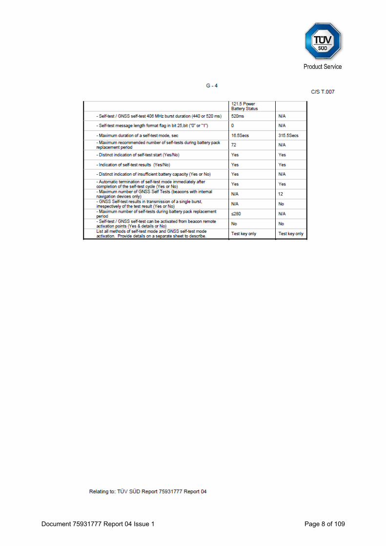
Document 75931777 Report 04 Issue 1 Page 8 of 109
12
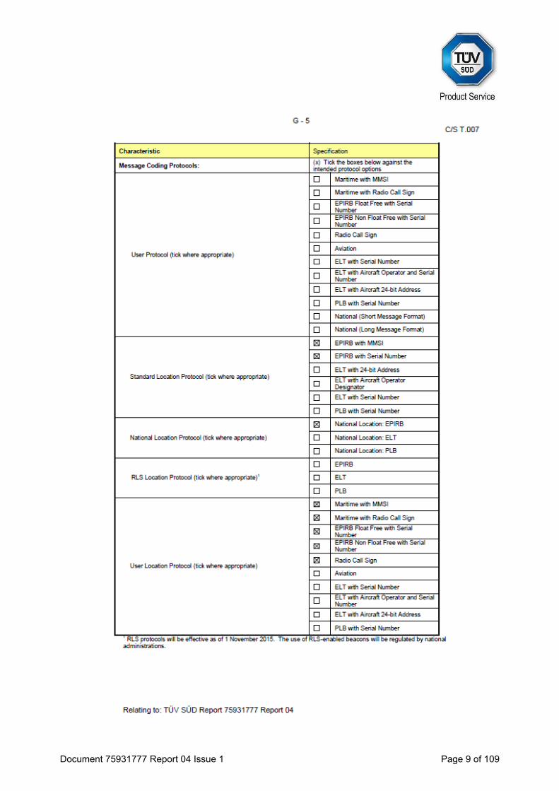
Document 75931777 Report 04 Issue 1 Page 9 of 109
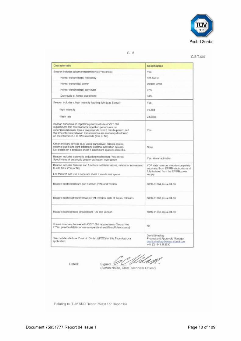
Document 75931777 Report 04 Issue 1 Page 10 of 109
Document 75931777 Report 04 Issue 1 Page 11 of 109
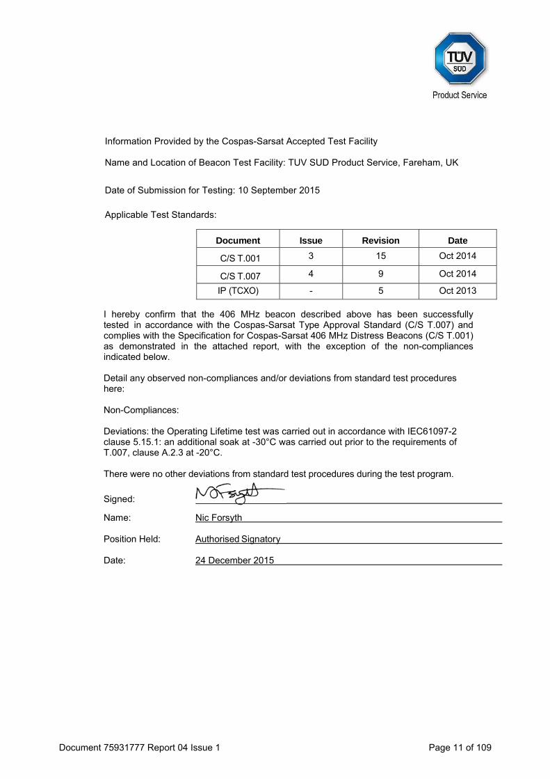
Information Provided by the Cospas-Sarsat Accepted Test Facility
Name and Location of Beacon Test Facility: TUV SUD Product Service, Fareham, UK
Date of Submission for Testing: 10 September 2015
Applicable Test Standards:
Document Issue Revision Date
C/S T.001 3 15 Oct 2014
C/S T.007 4 9 Oct 2014
IP (TCXO) - 5 Oct 2013
I hereby confirm that the 406 MHz beacon described above has been successfully tested in accordance with the Cospas-Sarsat Type Approval Standard (C/S T.007) and complies with the Specification for Cospas-Sarsat 406 MHz Distress Beacons (C/S T.001) as demonstrated in the attached report, with the exception of the non-compliances indicated below.
Detail any observed non-compliances and/or deviations from standard test procedures here: Non-Compliances: Deviations: the Operating Lifetime test was carried out in accordance with IEC61097-2 clause 5.15.1: an additional soak at -30°C was carried out prior to the requirements of T.007, clause A.2.3 at -20°C. There were no other deviations from standard test procedures during the test program.
Signed:
Name: Nic Forsyth
Position Held: Authorised Signatory
Date: 24 December 2015

Document 75931777 Report 04 Issue 1 Page 12 of 109
1.3 PRODUCT INFORMATION
1.3.1 Technical Description
The Equipment Under Test (EUT) was a Ocean Signal SafeSea E101V EPIRB as shown in the photograph below. A full technical description can be found in the manufacturer’s documentation.
Equipment Under Test
The following is a list of equipment provided by the manufacturer for Type Approval Testing:
Description Manufacturer Model S/No./Version
Automatic Release Housing Ocean Signal ARH101 N/A
EPIRB with VDR (Modified Conducted Output) Ocean Signal E101V 0800002P
Automatic Release Housing Ocean Signal ARH101 N/A
EPIRB with VDR Ocean Signal E101V 0800003P
EPIRB programming cable Ocean Signal N/A N/A
Crossover LAN Cable RS 405-5379 N/A
‘BeaconWidget’ Programming Software Ocean Signal N/A V01.07
Document 75931777 Report 04 Issue 1 Page 13 of 109
Physical Test Configuration
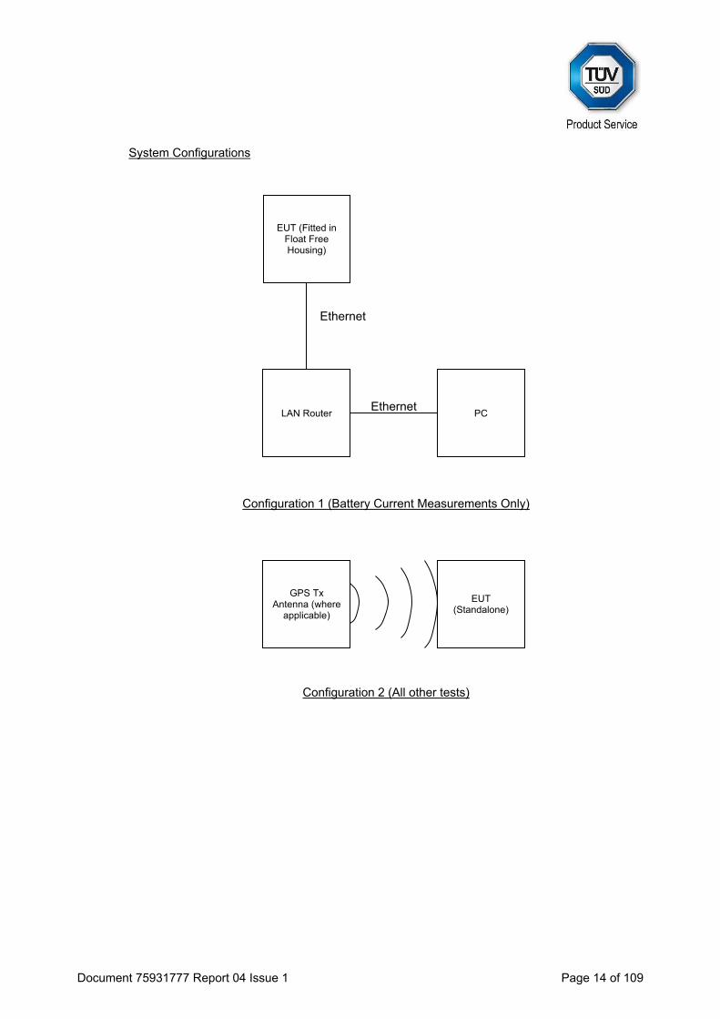
The Equipment Under Test (EUT) was operated using its own power source (internal battery). One EUT was configured so that the antenna port was connected to the 50Ω test system using a coaxial cable. The test configuration for all tests is identical with the exception of Antenna Characteristics, Satellite Qualitative and Navigation Tests. The second EUT was a fully packaged beacon, similar to the proposed production beacons equipped with its proper antenna. This EUT was used to perform Antenna Characteristics, Satellite Qualitative and Navigation Tests. The test configuration for these tests is a function of the beacon type and the operational environments supported by the beacon, as declared by the manufacturer. For Configuration 1 (see System Configurations below), the EUT was fitted into a manufacturer supplied Float Free Housing (see Photographs in Section 4). The EUT also incorporated a VDR module, which in accordance with the manufacturers’ information, is completely electrically isolated from the main EUT. To ensure that the VDR module did not affect EUT performance in any way, the VDR input was connected to an artificial network during battery current measurements. The manufacturer has declared that the EUT should not be activated whilst in the Float Free Housing. Therefore current measurements applied to Standby and Self Test modes only. The physical configurations for tests within this report are as follows: 1) EUT fitted in manufacturer supplied Float Free Housing, with VDR module networked to test
PC for: Battery Current Measurements (Standby and Self-Test modes only)
2) EUT ‘standalone’ – no ancillaries connected to the EUT, VDR module inactive for:
Electrical and Functional Tests at Constant Temperature Thermal Shock Operating Lifetime at Minimum Temperature Frequency Stability Test with Temperature Gradient Satellite Qualitative Beacon Antenna Test Navigation System Battery Current Measurements
Document 75931777 Report 04 Issue 1 Page 14 of 109
System Configurations
Configuration 1 (Battery Current Measurements Only)
Configuration 2 (All other tests)
EUT (Standalone)
GPS Tx Antenna (where
applicable)
EUT (Fitted in Float Free Housing)
PC LAN Router Ethernet
Ethernet
Document 75931777 Report 04 Issue 1 Page 15 of 109
1.3.2 Modes of Operation
Modes of operation of the EUT during testing were as follows: Off/Standby Mode
Main switch to “OFF” position No apparent activity
Self-test
Test switch to “TEST” position for 2 seconds (approx) List of items checked as per Customer Supplied Information (Application Form) Navigation data applied at ambient temperature
GNSS Self-test
Test switch to “TEST” position for 10 seconds (approx) List of items checked as per Customer Supplied Information (Application Form) Navigation data applied as applicable (e.g. none applied for timeout, data applied for
‘fast acquisition’) Operating
Main switch to “ON” position 121 Homer active and offset GPS operating in normal duty cycle for the following navigation input conditions No navigation data applied
All modes All mode descriptions are applicable to all tests unless otherwise stated. Additional methods of activation include:
Water contacts All Navigation input descriptions are applicable to all tests unless otherwise stated. During the first hour of operation, the manufacturers’ information states that in the absence of an external GPS signal, the EUT’s internal GPS receiver has the following duty cycle:
ON for 5 minutes OFF for 5 minutes.
For the Electrical and Functional Tests at Constant Temperature, listed in section A.2.1 of T.007 (excluding spurious output and self-test modes), measurements were performed for 20 minutes (after a 15 minute warm up period). This ensured that measurements were made during periods when the internal GPS receiver of the EUT was active and inactive. Spurious output measurements were made over a 20 hour period, during which, the Climatic test chamber was set to Ambient, +55°C, and -20°C.
Document 75931777 Report 04 Issue 1 Page 16 of 109
1.4 MODIFICATIONS Modification 0 - No modifications were made to the test sample during testing.
1.5 REPORT MODIFICATION RECORD Issue 1 – First Issue

Document 75931777 Report 04 Issue 1 Page 17 of 109
SECTION 2
TEST DETAILS
Emergency Beacons Testing of the Ocean Signal
SafeSea E101V EPIRB
Document 75931777 Report 04 Issue 1 Page 18 of 109
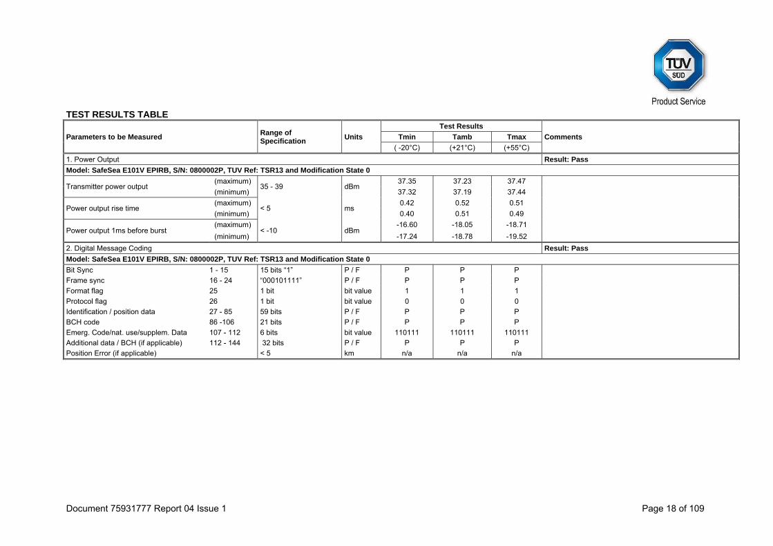
TEST RESULTS TABLE
Parameters to be Measured Range of Specification
Units
Test Results
Comments Tmin Tamb Tmax
( -20°C) (+21°C) (+55°C)
1. Power Output Result: Pass
Model: SafeSea E101V EPIRB, S/N: 0800002P, TUV Ref: TSR13 and Modification State 0
Transmitter power output (maximum)
35 - 39 dBm 37.35 37.23 37.47
(minimum) 37.32 37.19 37.44
Power output rise time (maximum)
< 5 ms 0.42 0.52 0.51
(minimum) 0.40 0.51 0.49
Power output 1ms before burst (maximum)
< -10 dBm -16.60 -18.05 -18.71
(minimum) -17.24 -18.78 -19.52
2. Digital Message Coding Result: Pass
Model: SafeSea E101V EPIRB, S/N: 0800002P, TUV Ref: TSR13 and Modification State 0
Bit Sync 1 - 15 15 bits “1” P / F P P P
Frame sync 16 - 24 “000101111” P / F P P P
Format flag 25 1 bit bit value 1 1 1
Protocol flag 26 1 bit bit value 0 0 0
Identification / position data 27 - 85 59 bits P / F P P P
BCH code 86 -106 21 bits P / F P P P
Emerg. Code/nat. use/supplem. Data 107 - 112 6 bits bit value 110111 110111 110111
Additional data / BCH (if applicable) 112 - 144 32 bits P / F P P P
Position Error (if applicable) < 5 km n/a n/a n/a

Document 75931777 Report 04 Issue 1 Page 19 of 109
Parameters to be Measured Range of Specification
Units
Test Results
Comments Tmin Tamb Tmax
( -20°C) (+21°C) (+55°C)
3. Digital Message Generator Result: Pass
Model: SafeSea E101V EPIRB, S/N: 0800002P, TUV Ref: TSR13 and Modification State 0
Repetition rate, TR:
Average TR 48.5 ≤ TRavg ≤ 51.5 seconds 50.166 50.209 50.209
Minimum TR 47.5 ≤ TRmin ≤ 48.0 seconds 47.705 47.721 47.705
Maximum TR 52.0 ≤ TRmax ≤ 52.5 seconds 52.011 52.026 52.026
Standard deviation 0.5 - 2.0 seconds 1.44 1.44 1.44
Bit rate
Minimum fb ≥ 396 bits/sec 400.10 400.10 400.10
Maximum fb ≤ 404 bits/sec 400.12 400.12 400.12
Total transmission time
Short message (maximum)
435.6 - 444.4 ms n/a n/a n/a
(minimum) n/a n/a n/a
Long message (maximum)
514.8 - 525.2 ms 518.92 518.95 518.98
(minimum) 518.87 518.89 518.91
Unmodulated carrier
Minimum T1 ≥ 158.4 ms 159.97 159.97 159.97
Maximum T1 ≤ 161.6 ms 160.03 160.03 160.04
First burst delay ≥ 47.5 seconds 50 50 50
Document 75931777 Report 04 Issue 1 Page 20 of 109
Parameters to be Measured Range of Specification
Units
Test Results
Comments Tmin Tamb Tmax
( -20°C) (+21°C) (+55°C)
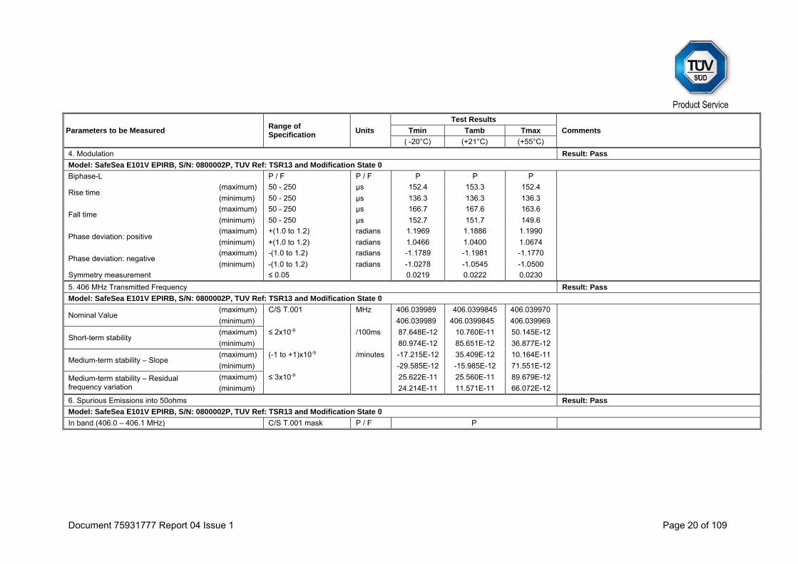
4. Modulation Result: Pass
Model: SafeSea E101V EPIRB, S/N: 0800002P, TUV Ref: TSR13 and Modification State 0
Biphase-L P / F P / F P P P
Rise time (maximum) 50 - 250 μs 152.4 153.3 152.4
(minimum) 50 - 250 μs 136.3 136.3 136.3
Fall time (maximum) 50 - 250 μs 166.7 167.6 163.6
(minimum) 50 - 250 μs 152.7 151.7 149.6
Phase deviation: positive (maximum) +(1.0 to 1.2) radians 1.1969 1.1886 1.1990
(minimum) +(1.0 to 1.2) radians 1.0466 1.0400 1.0674
Phase deviation: negative (maximum) -(1.0 to 1.2) radians -1.1789 -1.1981 -1.1770
(minimum) -(1.0 to 1.2) radians -1.0278 -1.0545 -1.0500
Symmetry measurement ≤ 0.05 0.0219 0.0222 0.0230
5. 406 MHz Transmitted Frequency Result: Pass
Model: SafeSea E101V EPIRB, S/N: 0800002P, TUV Ref: TSR13 and Modification State 0
Nominal Value (maximum) C/S T.001 MHz 406.039989 406.0399845 406.039970
(minimum) 406.039989 406.0399845 406.039969
Short-term stability (maximum) ≤ 2x10⁻⁹ /100ms 87.648E-12 10.760E-11 50.145E-12
(minimum) 80.974E-12 85.651E-12 36.877E-12
Medium-term stability – Slope (maximum) (-1 to +1)x10-9 /minutes -17.215E-12 35.409E-12 10.164E-11
(minimum) -29.585E-12 -15.985E-12 71.551E-12
Medium-term stability – Residual frequency variation
(maximum) ≤ 3x10⁻⁹ 25.622E-11 25.560E-11 89.679E-12
(minimum) 24.214E-11 11.571E-11 66.072E-12
6. Spurious Emissions into 50ohms Result: Pass
Model: SafeSea E101V EPIRB, S/N: 0800002P, TUV Ref: TSR13 and Modification State 0
In band (406.0 – 406.1 MHz) C/S T.001 mask P / F P
Document 75931777 Report 04 Issue 1 Page 21 of 109
Parameters to be Measured Range of Specification
Units
Test Results
Comments Tmin Tamb Tmax
( -20°C) (+21°C) (+55°C)
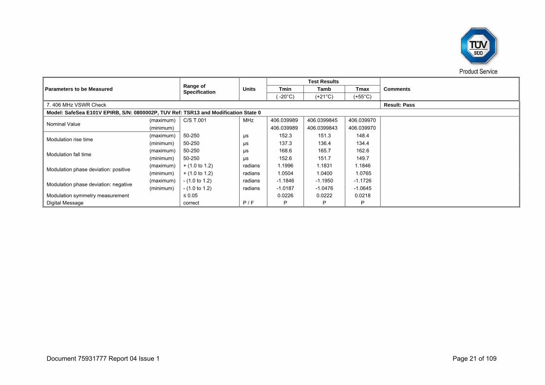
7. 406 MHz VSWR Check Result: Pass
Model: SafeSea E101V EPIRB, S/N: 0800002P, TUV Ref: TSR13 and Modification State 0
Nominal Value (maximum) C/S T.001 MHz 406.039989 406.0399845 406.039970
(minimum) 406.039989 406.0399843 406.039970
Modulation rise time (maximum) 50-250 μs 152.3 151.3 148.4
(minimum) 50-250 μs 137.3 136.4 134.4
Modulation fall time (maximum) 50-250 μs 168.6 165.7 162.6
(minimum) 50-250 μs 152.6 151.7 149.7
Modulation phase deviation: positive (maximum) + (1.0 to 1.2) radians 1.1996 1.1831 1.1846
(minimum) + (1.0 to 1.2) radians 1.0504 1.0400 1.0765
Modulation phase deviation: negative (maximum) - (1.0 to 1.2) radians -1.1846 -1.1950 -1.1726
(minimum) - (1.0 to 1.2) radians -1.0187 -1.0476 -1.0645
Modulation symmetry measurement ≤ 0.05 0.0226 0.0222 0.0218
Digital Message correct P / F P P P
Document 75931777 Report 04 Issue 1 Page 22 of 109
Parameters to be Measured Range of Specification
Units
Test Results
Comments Tmin Tamb Tmax
( -20°C) (+21°C) (+55°C)
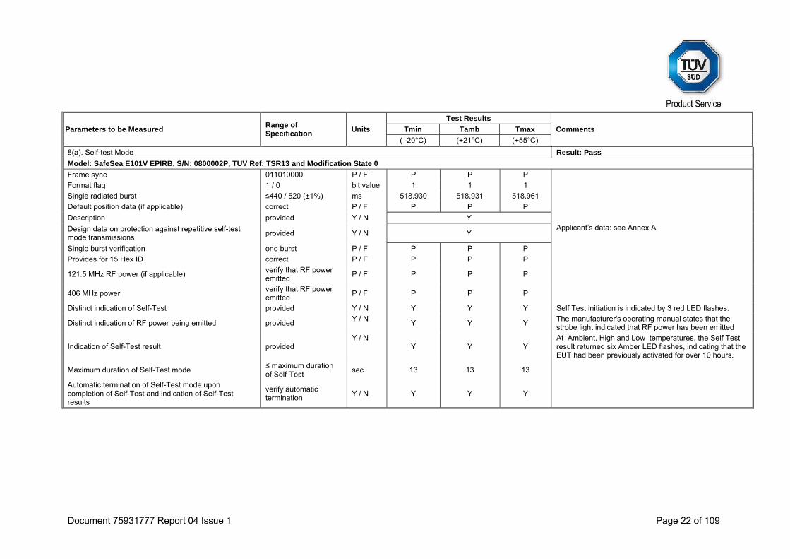
8(a). Self-test Mode Result: Pass
Model: SafeSea E101V EPIRB, S/N: 0800002P, TUV Ref: TSR13 and Modification State 0
Frame sync 011010000 P / F P P P
Format flag 1 / 0 bit value 1 1 1
Single radiated burst ≤440 / 520 (±1%) ms 518.930 518.931 518.961
Default position data (if applicable) correct P / F P P P
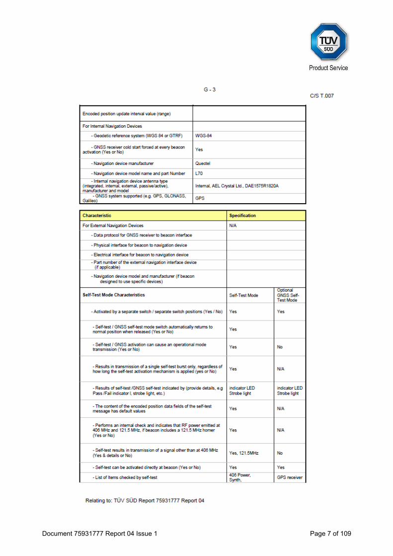
Description provided Y / N Y Applicant’s data: see Annex A Design data on protection against repetitive self-test
mode transmissions provided Y / N Y
Single burst verification one burst P / F P P P
Provides for 15 Hex ID correct P / F P P P
121.5 MHz RF power (if applicable) verify that RF power emitted
P / F P P P
406 MHz power verify that RF power emitted
P / F P P P
Distinct indication of Self-Test provided Y / N Y Y Y Self Test initiation is indicated by 3 red LED flashes.
Distinct indication of RF power being emitted provided Y / N
Y Y Y The manufacturer's operating manual states that the strobe light indicated that RF power has been emitted
Indication of Self-Test result provided Y / N
Y Y Y At Ambient, High and Low temperatures, the Self Test result returned six Amber LED flashes, indicating that the EUT had been previously activated for over 10 hours.
Maximum duration of Self-Test mode ≤ maximum duration of Self-Test
sec 13 13 13
Automatic termination of Self-Test mode upon completion of Self-Test and indication of Self-Test results
verify automatic termination
Y / N Y Y Y
Document 75931777 Report 04 Issue 1 Page 23 of 109
Parameters to be Measured Range of Specification
Units
Test Results
Comments Tmin Tamb Tmax
( -20°C) (+21°C) (+55°C)
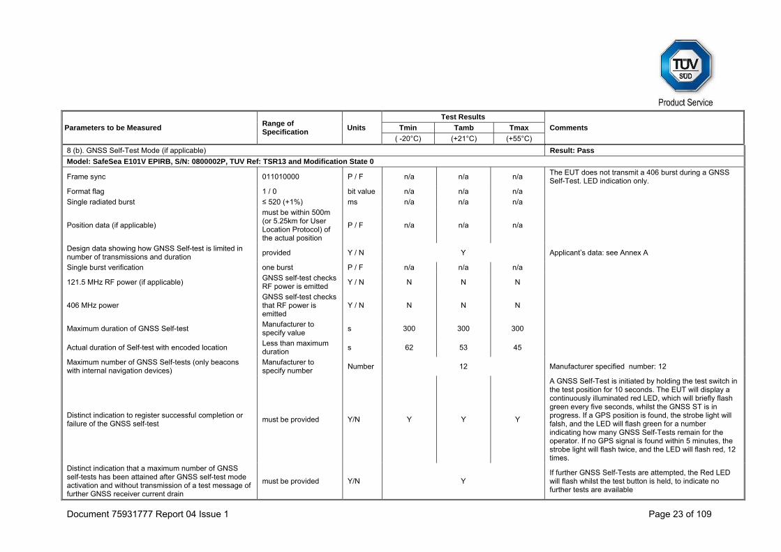
8 (b). GNSS Self-Test Mode (if applicable) Result: Pass
Model: SafeSea E101V EPIRB, S/N: 0800002P, TUV Ref: TSR13 and Modification State 0
Frame sync 011010000 P / F n/a n/a n/a The EUT does not transmit a 406 burst during a GNSS Self-Test. LED indication only.
Format flag 1 / 0 bit value n/a n/a n/a
Single radiated burst ≤ 520 (+1%) ms n/a n/a n/a
Position data (if applicable)
must be within 500m (or 5.25km for User Location Protocol) of the actual position
P / F n/a n/a n/a
Design data showing how GNSS Self-test is limited in number of transmissions and duration
provided Y / N Y Applicant’s data: see Annex A
Single burst verification one burst P / F n/a n/a n/a
121.5 MHz RF power (if applicable) GNSS self-test checks RF power is emitted
Y / N N N N
406 MHz power GNSS self-test checks that RF power is emitted
Y / N N N N
Maximum duration of GNSS Self-test Manufacturer to specify value
s 300 300 300
Actual duration of Self-test with encoded location Less than maximum duration
s 62 53 45
Maximum number of GNSS Self-tests (only beacons with internal navigation devices)
Manufacturer to specify number
Number 12 Manufacturer specified number: 12
Distinct indication to register successful completion or failure of the GNSS self-test
must be provided Y/N Y Y Y
A GNSS Self-Test is initiated by holding the test switch in the test position for 10 seconds. The EUT will display a continuously illuminated red LED, which will briefly flash green every five seconds, whilst the GNSS ST is in progress. If a GPS position is found, the strobe light will falsh, and the LED will flash green for a number indicating how many GNSS Self-Tests remain for the operator. If no GPS signal is found within 5 minutes, the strobe light will flash twice, and the LED will flash red, 12 times.
Distinct indication that a maximum number of GNSS self-tests has been attained after GNSS self-test mode activation and without transmission of a test message of further GNSS receiver current drain
must be provided Y/N Y If further GNSS Self-Tests are attempted, the Red LED will flash whilst the test button is held, to indicate no further tests are available
Document 75931777 Report 04 Issue 1 Page 24 of 109
Parameters to be Measured Range of Specification
Units Test Results Comments
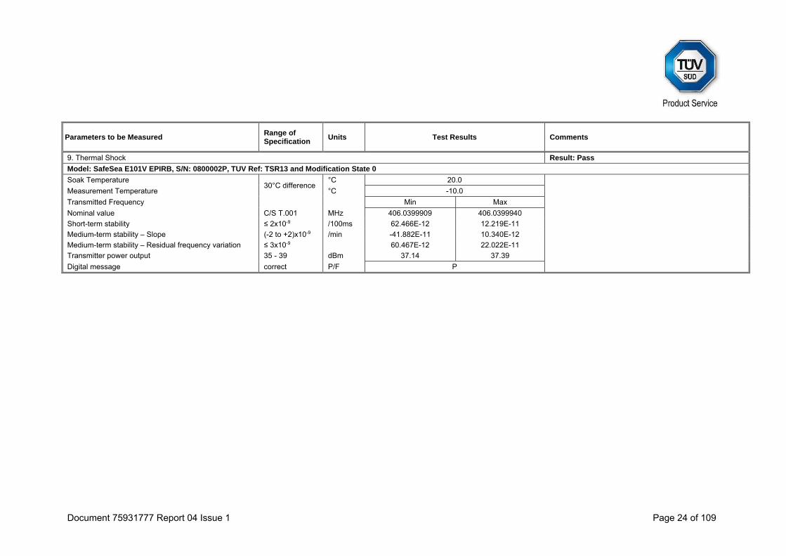
9. Thermal Shock Result: Pass
Model: SafeSea E101V EPIRB, S/N: 0800002P, TUV Ref: TSR13 and Modification State 0
Soak Temperature 30°C difference
°C 20.0
Measurement Temperature °C -10.0
Transmitted Frequency Min Max
Nominal value C/S T.001 MHz 406.0399909 406.0399940
Short-term stability ≤ 2x10⁻⁹ /100ms 62.466E-12 12.219E-11
Medium-term stability – Slope (-2 to +2)x10-9 /min -41.882E-11 10.340E-12
Medium-term stability – Residual frequency variation ≤ 3x10⁻⁹ 60.467E-12 22.022E-11
Transmitter power output 35 - 39 dBm 37.14 37.39
Digital message correct P/F P

Document 75931777 Report 04 Issue 1 Page 25 of 109
Parameters to be Measured Range of Specification
Units Test Results Comments
10. Operating Lifetime at Minimum Temperature Result: Pass
Model: SafeSea E101V EPIRB, S/N: 0800002P, TUV Ref: TSR13 and Modification State 0
Pre-test battery discharge duration (operating) required Hours 11.61 Capacity discharge required : 0.4123Ah
Pre-test battery discharge duration (operating) Hours 18.5 Capacity discharge actual : 06571Ah
Duration >24 Hours 214.5 Hours at Tmin = -20°C
Effective Operating Lifetime duration >24 Hours 214.5 Hours at Tmin = -20°C End of test taken as 168 hours (Manufacturer declared value)
Transmitted Frequency Min Max
Nominal value C/S T.001 MHz 406.0399941 406.0400086
Short-term stability ≤ 2x10⁻⁹ /100ms 34.397E-12 43.629E-11
Medium-term stability – Slope (-1 to +1)x10-9 /min -7.13E-11 1.20E-10 Results for MTS-Slope and MTS-Residual, exclude the first 30 mins of data. Medium-term stability – Residual frequency variation ≤ 3x10⁻⁹ 5.82E-11 1.99E-09
Transmitter power output 35 - 39 dBm 36.42 37.39
Digital message correct P/F P
Homer transmitter continuous operation during the lifetime test
hours >214.5
Start of Test End of Test
Homer frequency MHz 121.499 121.499
Homer peak power level dBm 18.756 19.37
Homer transmitter duty cycle % 96.8 97.1

Document 75931777 Report 04 Issue 1 Page 26 of 109
Parameters to be Measured Range of Specification
Units Test Results Comments
11. Temperature Gradient (5°C/hr) Result: Pass
Model: SafeSea E101V EPIRB, S/N: 0800002P, TUV Ref: TSR13 and Modification State 0
Full Test
Transmitted Frequency Min Max
Nominal value C/S T.007 MHz 406.0399687 406.0399971
Short-term stability ≤ 2x10⁻⁹ /100ms 39.496E-12 24.838E-11
Medium-term stability – Slope (-1 to +1)x10-9 /min -3.99E-11 4.15E-11 Data for points A to B, C+15 min to D and E+15 min to F
(-2 to +2)x10-9 /min -1.71E-10 1.71E-10 Data for points B to C+15 min and D to E+15 min
Medium-term stability – Residual frequency variation ≤ 3x10⁻⁹ 36.012E-12 27.957E-11
Transmitter power output 35 – 39 dBm 36.92 37.43
Digital message correct P/F P
Interim TCXO Procedure correct P/F P See test results section (2.8) for result table
12. Oscillator Aging
N/A
Data provided Y / N Y Applicant’s data: see Annex A
13. Protection Against Continuous Transmission
Description provided Y / N Y Applicant’s data: see Annex A
14. Satellite Qualitative Tests Result: Pass
Model: SafeSea E101V EPIRB, S/N: 0800003P, TUV Ref: TSR1 and Modification State 0
Test Configuration As per C/S T.007
Configuration
5 6 7 8
15 Hex ID Decoded by LUT correct P / F P - P P
Doppler Location results with error ≤ 5km ≥ 80 % 100 - 92.86 86.66
Document 75931777 Report 04 Issue 1 Page 27 of 109
Parameters to be Measured Range of Specification
Units Test Results Comments
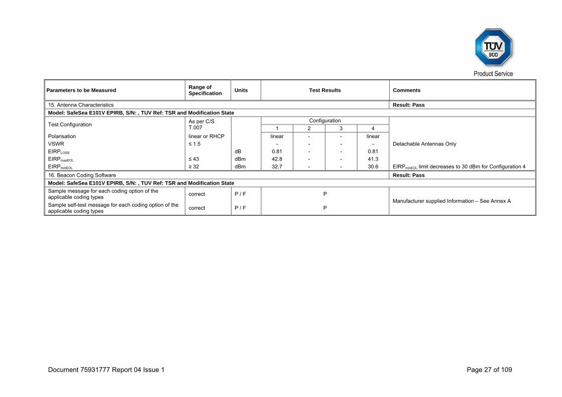
15. Antenna Characteristics Result: Pass
Model: SafeSea E101V EPIRB, S/N: , TUV Ref: TSR and Modification State
Test Configuration As per C/S T.007
Configuration
1 2 3 4
Polarisation linear or RHCP linear - - linear
VSWR ≤ 1.5 - - - - Detachable Antennas Only
EIRPLOSS dB 0.81 - - 0.81
EIRPmaxEOL ≤ 43 dBm 42.8 - - 41.3
EIRPminEOL ≥ 32 dBm 32.7 - - 30.6 EIRPminEOL limit decreases to 30 dBm for Configuration 4
16. Beacon Coding Software Result: Pass
Model: SafeSea E101V EPIRB, S/N: , TUV Ref: TSR and Modification State
Sample message for each coding option of the applicable coding types
correct P / F P Manufacturer supplied Information – See Annex A
Sample self-test message for each coding option of the applicable coding types
correct P / F P
Document 75931777 Report 04 Issue 1 Page 28 of 109
Parameters to be Measured Range of Specification
Units Test Results Comments
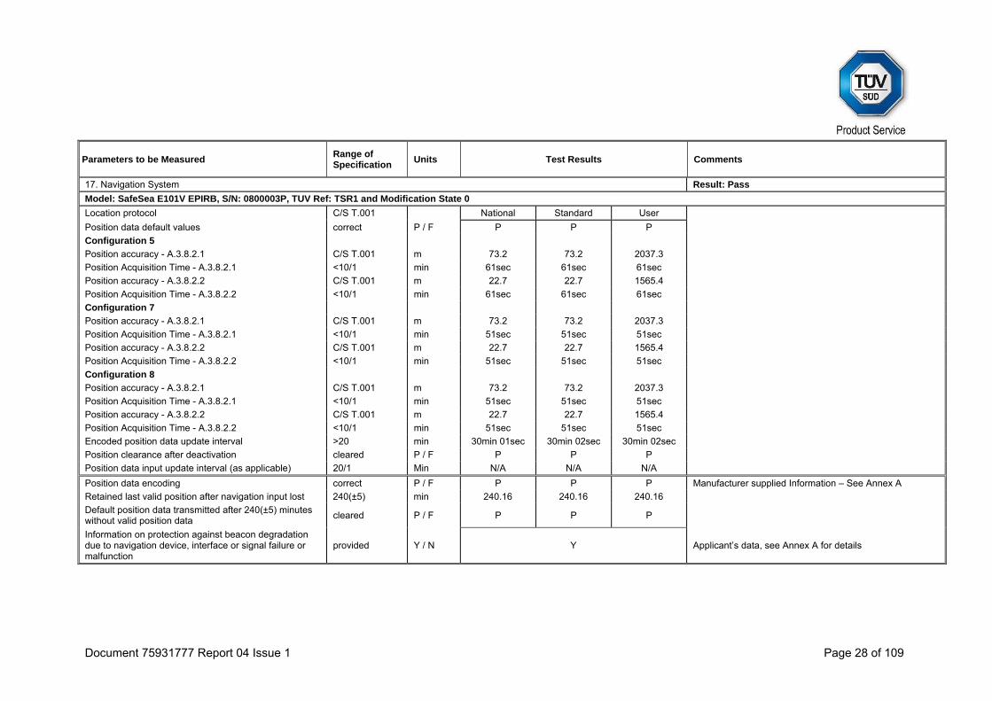
17. Navigation System Result: Pass
Model: SafeSea E101V EPIRB, S/N: 0800003P, TUV Ref: TSR1 and Modification State 0
Location protocol C/S T.001 National Standard User
Position data default values correct P / F P P P
Configuration 5
Position accuracy - A.3.8.2.1 C/S T.001 m 73.2 73.2 2037.3
Position Acquisition Time - A.3.8.2.1 <10/1 min 61sec 61sec 61sec
Position accuracy - A.3.8.2.2 C/S T.001 m 22.7 22.7 1565.4
Position Acquisition Time - A.3.8.2.2 <10/1 min 61sec 61sec 61sec
Configuration 7
Position accuracy - A.3.8.2.1 C/S T.001 m 73.2 73.2 2037.3
Position Acquisition Time - A.3.8.2.1 <10/1 min 51sec 51sec 51sec
Position accuracy - A.3.8.2.2 C/S T.001 m 22.7 22.7 1565.4
Position Acquisition Time - A.3.8.2.2 <10/1 min 51sec 51sec 51sec
Configuration 8
Position accuracy - A.3.8.2.1 C/S T.001 m 73.2 73.2 2037.3
Position Acquisition Time - A.3.8.2.1 <10/1 min 51sec 51sec 51sec
Position accuracy - A.3.8.2.2 C/S T.001 m 22.7 22.7 1565.4
Position Acquisition Time - A.3.8.2.2 <10/1 min 51sec 51sec 51sec
Encoded position data update interval >20 min 30min 01sec 30min 02sec 30min 02sec
Position clearance after deactivation cleared P / F P P P
Position data input update interval (as applicable) 20/1 Min N/A N/A N/A
Position data encoding correct P / F P P P Manufacturer supplied Information – See Annex A
Retained last valid position after navigation input lost 240(±5) min 240.16 240.16 240.16
Default position data transmitted after 240(±5) minutes without valid position data
cleared P / F P P P
Information on protection against beacon degradation due to navigation device, interface or signal failure or malfunction
provided Y / N Y Applicant’s data, see Annex A for details

Document 75931777 Report 04 Issue 1 Page 29 of 109
2.1 DIGITAL MESSAGE
2.1.1 Specification
Cospas-Sarsat T.007, Clause A.2.1 (b)
2.1.2 Equipment Under Test and Modification State
E101V S/N: 0800002P - Modification State 0
2.1.3 Date of Test
19 October 2015, 20 October 2015 & 22 October 2015
2.1.4 Test Equipment Used
The major items of test equipment used for the above tests are identified in Section 3.1.
2.1.5 Environmental Conditions
Ambient Temperature 22.4 - 23.3°C Relative Humidity 45.6 - 49.2%
Document 75931777 Report 04 Issue 1 Page 30 of 109
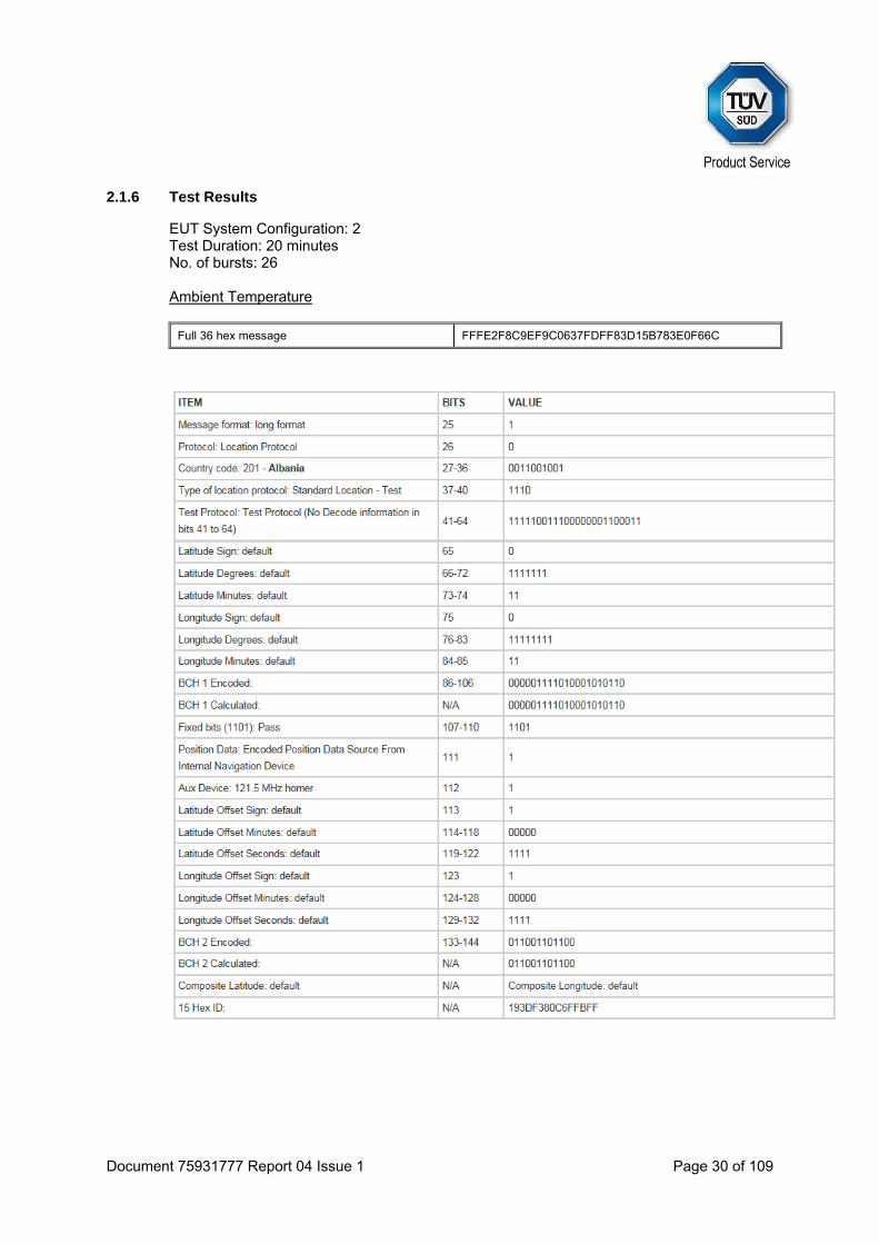
2.1.6 Test Results
EUT System Configuration: 2 Test Duration: 20 minutes No. of bursts: 26 Ambient Temperature
Full 36 hex message FFFE2F8C9EF9C0637FDFF83D15B783E0F66C
Document 75931777 Report 04 Issue 1 Page 31 of 109
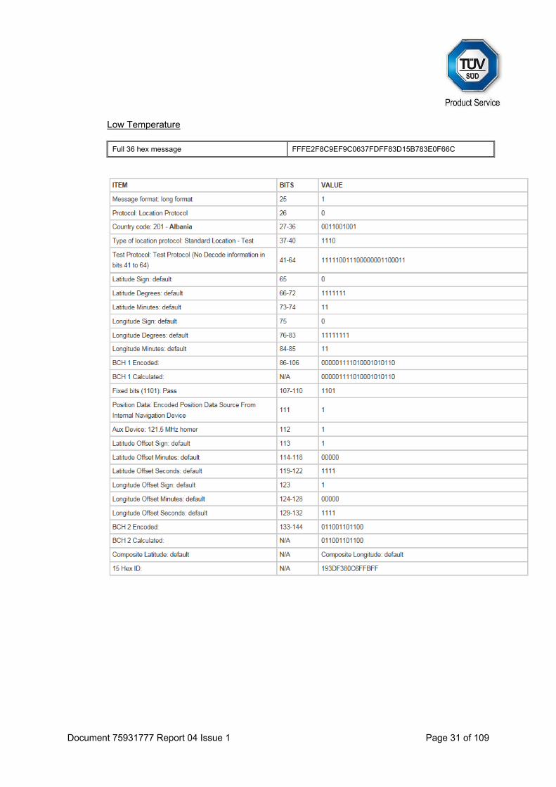
Low Temperature
Full 36 hex message FFFE2F8C9EF9C0637FDFF83D15B783E0F66C
Document 75931777 Report 04 Issue 1 Page 32 of 109
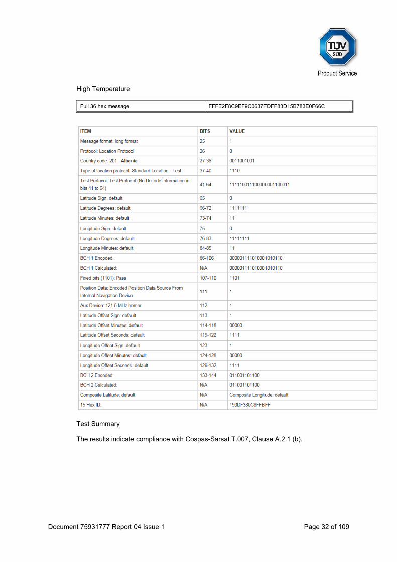
High Temperature
Full 36 hex message FFFE2F8C9EF9C0637FDFF83D15B783E0F66C
Test Summary The results indicate compliance with Cospas-Sarsat T.007, Clause A.2.1 (b).

Document 75931777 Report 04 Issue 1 Page 33 of 109
2.2 MODULATION
2.2.1 Specification
Cospas-Sarsat T.007, Clause A.2.1 (d)
2.2.2 Equipment Under Test and Modification State
E101V S/N: 0800002P - Modification State 0
2.2.3 Date of Test
19 October 2015, 20 October 2015 & 22 October 2015
2.2.4 Test Equipment Used
The major items of test equipment used for the above tests are identified in Section 3.1.
2.2.5 Environmental Conditions
Ambient Temperature 22.4 - 23.3°C Relative Humidity 45.6 - 49.2%
Document 75931777 Report 04 Issue 1 Page 34 of 109
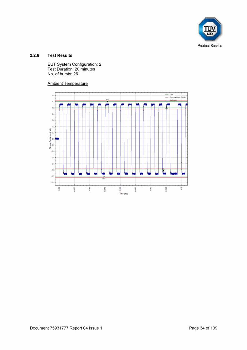
2.2.6 Test Results
EUT System Configuration: 2 Test Duration: 20 minutes No. of bursts: 26 Ambient Temperature
Document 75931777 Report 04 Issue 1 Page 35 of 109
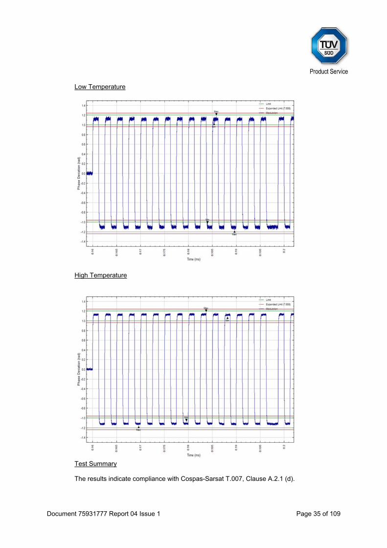
Low Temperature
High Temperature
Test Summary The results indicate compliance with Cospas-Sarsat T.007, Clause A.2.1 (d).
Document 75931777 Report 04 Issue 1 Page 36 of 109
2.3 SPURIOUS EMISSION INTO 50 OHMS
2.3.1 Specification
Cospas-Sarsat T.007, Clause A.2.1 (f)
2.3.2 Equipment Under Test and Modification State
E101V S/N: 0800002P - Modification State 0
2.3.3 Date of Test
20 October 2015
2.3.4 Test Equipment Used
The major items of test equipment used for the above tests are identified in Section 3.1.
2.3.5 Environmental Conditions
Ambient Temperature 22.1°C Relative Humidity 44.6%

Document 75931777 Report 04 Issue 1 Page 37 of 109
2.3.6 Test Results
EUT System Configuration: 2
Test Duration: 20 hours
Combined Ambient, Low and High Temperature
Test Summary The results indicate compliance with Cospas-Sarsat T.007, Clause A.2.1 (f).
Ref 13.19 dBm #Atten 25 dBPeakLog10dB/
V1 S2S3 FC
AA
Start 406 MHz#Res BW 100 Hz #VBW 100 Hz
Stop 406.1 MHzSweep 6.82 s (1001 pts)
*
Ext Ref
Document 75931777 Report 04 Issue 1 Page 38 of 109
2.4 406 MHz VSWR CHECK
2.4.1 Specification
Cospas-Sarsat T.007, Clause A.2.1 (g)
2.4.2 Equipment Under Test and Modification State
E101V S/N: 0800002P - Modification State 0
2.4.3 Date of Test
19 October 2015, 21 October 2015 & 22 October 2015
2.4.4 Test Equipment Used
The major items of test equipment used for the above tests are identified in Section 3.1.
2.4.5 Environmental Conditions
Ambient Temperature 22.4 - 23.4°C Relative Humidity 41.3 - 49.2%

Document 75931777 Report 04 Issue 1 Page 39 of 109
2.4.6 Test Results
EUT System Configuration: 2 Test Duration: 20 minutes No. of bursts: 26 Ambient Temperature
Full 36 hex message FFFE2F8C9EF9C0637FDFF83D15B783E0F66C
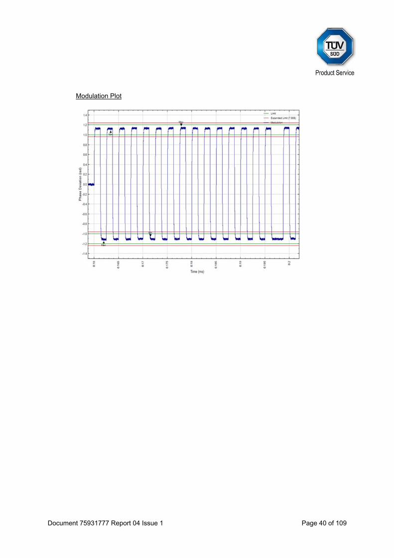
Document 75931777 Report 04 Issue 1 Page 40 of 109
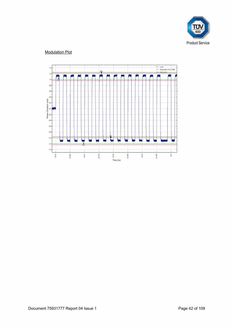
Modulation Plot

Document 75931777 Report 04 Issue 1 Page 41 of 109
Low Temperature
Full 36 hex message FFFE2F8C9EF9C0637FDFF83D15B783E0F66C
Document 75931777 Report 04 Issue 1 Page 42 of 109
Modulation Plot

Document 75931777 Report 04 Issue 1 Page 43 of 109
High Temperature
Full 36 hex message FFFE2F8C9EF9C0637FDFF83D15B783E0F66C

Document 75931777 Report 04 Issue 1 Page 44 of 109
Modulation Plot
Test Summary The results indicate compliance with Cospas-Sarsat T.007, Clause A.2.1 (g).

Document 75931777 Report 04 Issue 1 Page 45 of 109
2.5 SELF-TEST MODES
2.5.1 Specification
Cospas-Sarsat T.007, Clause A.2.1 (h)
2.5.2 Equipment Under Test and Modification State
E101V S/N: 0800002P - Modification State 0
2.5.3 Date of Test
22 October 2015, 23 October 2015 & 21 November 2015
2.5.4 Test Equipment Used
The major items of test equipment used for the above tests are identified in Section 3.1.
2.5.5 Environmental Conditions
Ambient Temperature 23.3 - 23.6°C Relative Humidity 34.0 - 48.3%
Document 75931777 Report 04 Issue 1 Page 46 of 109
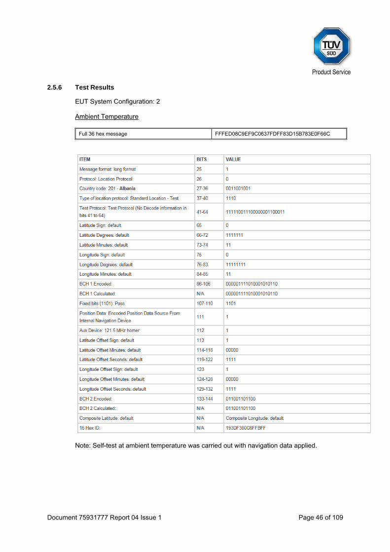
2.5.6 Test Results
EUT System Configuration: 2 Ambient Temperature
Full 36 hex message FFFED08C9EF9C0637FDFF83D15B783E0F66C
Note: Self-test at ambient temperature was carried out with navigation data applied.

Document 75931777 Report 04 Issue 1 Page 47 of 109
Low Temperature
Full 36 hex message FFFED08C9EF9C0637FDFF83D15B783E0F66C
Document 75931777 Report 04 Issue 1 Page 48 of 109
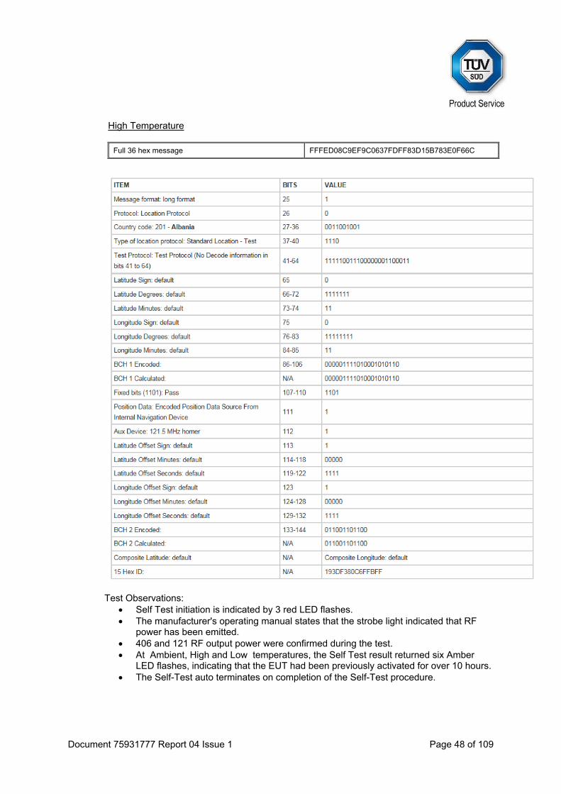
High Temperature
Full 36 hex message FFFED08C9EF9C0637FDFF83D15B783E0F66C
Test Observations: Self Test initiation is indicated by 3 red LED flashes. The manufacturer's operating manual states that the strobe light indicated that RF
power has been emitted. 406 and 121 RF output power were confirmed during the test. At Ambient, High and Low temperatures, the Self Test result returned six Amber
LED flashes, indicating that the EUT had been previously activated for over 10 hours. The Self-Test auto terminates on completion of the Self-Test procedure.
Document 75931777 Report 04 Issue 1 Page 49 of 109
GNSS Self-test mode No results other than those stated in the summary table. EUT does not transmit a 406 burst during a GNSS Self-Test, regardless of the GPS input conditions. EUT provides LED indications only. Test Observations:
A GNSS Self-Test was initiated by holding the test switch in the test position for 10 seconds. The EUT displayed a continuously illuminated red LED, which briefly flashed green every five seconds, whilst the GNSS ST was in progress. When a GPS position was found, the strobe light flashed, and the LED flashed green for a number indicating how many GNSS Self-Tests remained for the operator. Where no GPS signal was found within 5 minutes, the strobe light flashed twice, and the LED flashed red 12 times.
Maximum number of GNSS Self-Tests confirmed as 12. If further GNSS Self-Tests were attempted, the Red LED flashed whilst the test
button was held, to indicate no further tests were available.
Test Summary The results indicate compliance with Cospas-Sarsat T.007, Clause A.2.1 (h).

Document 75931777 Report 04 Issue 1 Page 50 of 109
2.6 THERMAL SHOCK
2.6.1 Specification
Cospas-Sarsat T.007, Clause A.2.2
2.6.2 Equipment Under Test and Modification State
E101V S/N: 0800002P - Modification State 0
2.6.3 Date of Test
22 October 2015
2.6.4 Test Equipment Used
The major items of test equipment used for the above tests are identified in Section 3.1.
2.6.5 Environmental Conditions
Ambient Temperature 23.1°C Relative Humidity 38.6%
Document 75931777 Report 04 Issue 1 Page 51 of 109
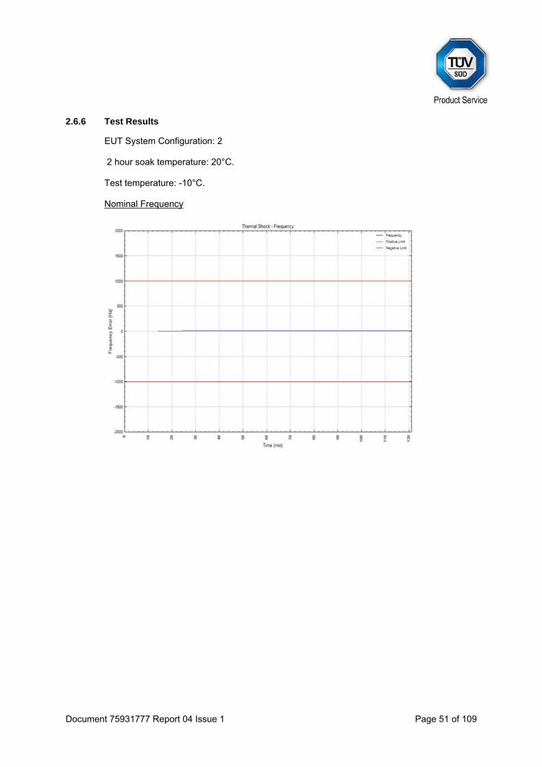
2.6.6 Test Results
EUT System Configuration: 2 2 hour soak temperature: 20°C. Test temperature: -10°C. Nominal Frequency

Document 75931777 Report 04 Issue 1 Page 52 of 109
Short Term Stability
Medium Term Stability, Mean Slope

Document 75931777 Report 04 Issue 1 Page 53 of 109
Medium Term Stability, Residual Frequency Variation
Output Power

Document 75931777 Report 04 Issue 1 Page 54 of 109
Digital Message
Full 36 hex message FFFE2F8C9EF9C0637FDFF83D15B783E0F66C
Test Summary The results indicate compliance with Cospas-Sarsat T.007, Clause A.2.2.
Document 75931777 Report 04 Issue 1 Page 55 of 109
2.7 OPERATING LIFETIME AT MINIMUM TEMPERATURE
2.7.1 Specification
Cospas-Sarsat T.007, Clause A.2.3 Note: the Operating Lifetime test was carried out in accordance with IEC61097-2 clause 5.15.1: an additional soak at -30°C was carried out prior to the requirements of T.007, clause A.2.3 at -20°C.
2.7.2 Equipment Under Test and Modification State
E101V S/N: 0800002P - Modification State 0
2.7.3 Date of Test
29 October 2015 & 30 October 2015
2.7.4 Test Equipment Used
The major items of test equipment used for the above tests are identified in Section 3.1.
2.7.5 Environmental Conditions
Ambient Temperature 22.3 - 22.7°C Relative Humidity 59.1 - 64.3%

Document 75931777 Report 04 Issue 1 Page 56 of 109
2.7.6 Test Results
EUT System Configuration: 2 End of test taken as 168 hours (Manufacturer declared value) Nominal Frequency

Document 75931777 Report 04 Issue 1 Page 57 of 109
Short Term Stability
Medium Term Stability, Mean Slope
Document 75931777 Report 04 Issue 1 Page 58 of 109
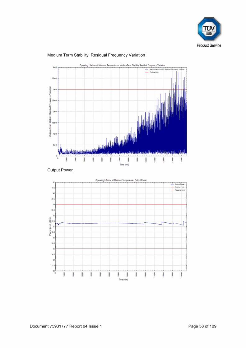
Medium Term Stability, Residual Frequency Variation
Output Power

Document 75931777 Report 04 Issue 1 Page 59 of 109
Digital Message
Full 36 hex message FFFE2F8C9EF9C0637FDFF83D15B783E0F66C

Document 75931777 Report 04 Issue 1 Page 60 of 109
Test Data (0 min - 30 min)
Burst Frequency (MHz) STS /100ms MTS-Slope /min MTS-Var Power (dBm) Time (hours)
1 - - - - 36.42 0.00
2 - - - - 37.22 0.01
3 - - - - 37.31 0.03
4 - - - - 37.33 0.04
5 - - - - 37.35 0.06
6 - - - - 37.22 0.07
7 - - - - 37.22 0.08
8 - - - - 37.22 0.10
9 - - - - 37.21 0.11
10 - - - - 37.21 0.13
11 - - - - 37.21 0.14
12 - - - - 37.21 0.15
13 - - - - 37.2 0.17
14 - - - - 37.19 0.18
15 - - - - 37.19 0.19
16 - - - - 37.32 0.21
17 - - - - 37.32 0.22
18 406.0400086 8.46E-11 -8.20E-09 1.38E-08 37.32 0.24
19 406.0400064 8.27E-11 -7.33E-09 1.49E-08 37.32 0.25
20 406.0400043 8.21E-11 -6.44E-09 1.57E-08 37.32 0.26
21 406.0400023 8.58E-11 -5.44E-09 1.59E-08 37.31 0.28
22 406.0400005 8.71E-11 -4.37E-09 1.54E-08 37.31 0.29
23 406.0399989 8.67E-11 -3.28E-09 1.39E-08 37.31 0.31
24 406.0399974 9.11E-11 -2.21E-09 1.14E-08 37.31 0.32
25 406.0399962 8.72E-11 -1.22E-09 7.63E-09 37.31 0.33
26 406.0399953 7.92E-11 -5.03E-10 3.60E-09 37.3 0.35
27 406.0399948 9.25E-11 -1.51E-10 6.09E-10 37.31 0.36
28 406.0399948 9.27E-11 -1.01E-10 2.93E-10 37.3 0.38
29 406.0399947 9.18E-11 -9.23E-11 2.68E-10 37.3 0.39
30 406.0399947 9.13E-11 -8.39E-11 2.49E-10 37.31 0.40
31 406.0399946 9.37E-11 -7.26E-11 2.54E-10 37.3 0.42
32 406.0399946 9.26E-11 -6.77E-11 2.56E-10 37.3 0.43
33 406.0399946 9.23E-11 -6.02E-11 2.81E-10 37.3 0.44
34 406.0399946 9.12E-11 -5.16E-11 2.96E-10 37.3 0.46
35 406.0399946 9.05E-11 -5.46E-11 2.86E-10 37.3 0.47
36 406.0399946 8.96E-11 -5.38E-11 2.87E-10 37.29 0.49
37 406.0399946 8.67E-11 -5.75E-11 2.92E-10 37.29 0.50

Document 75931777 Report 04 Issue 1 Page 61 of 109
121 Homing Transmitter - Duty Cycle (Start of Test) On Time
On+Off Time
Duty Cycle = 49.95 / 51.6 = 0.968 = 96.8%
11:45:57 Oct 30, 2015
Ref -5 dBm #Atten 5 dBMkr1 49.95 s
-0.171 dB PeakLog10dB/
V1 S2S3 FS
AA
Center 121.5 MHzRes BW 30 kHz VBW 30 kHz
Span 0 HzSweep 60 s (401 pts)
11R
*
Marker 49.95000000 s-0.171 dB
11:44:57 Oct 30, 2015
Ref -5 dBm #Atten 5 dBMkr1 51.6 s
-0.266 dB PeakLog10dB/
V1 S2S3 FS
AA
Center 121.5 MHzRes BW 30 kHz VBW 30 kHz
Span 0 HzSweep 60 s (401 pts)
11R
*
Document 75931777 Report 04 Issue 1 Page 62 of 109
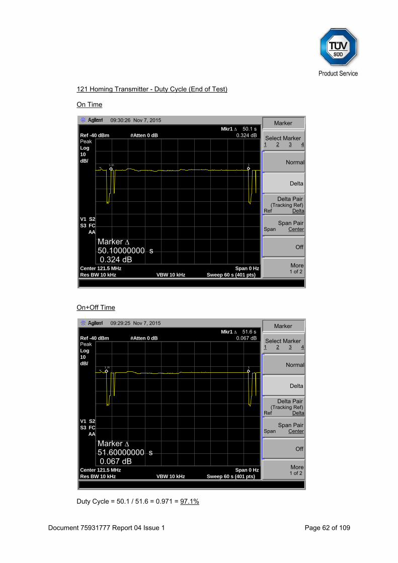
121 Homing Transmitter - Duty Cycle (End of Test) On Time
On+Off Time
Duty Cycle = 50.1 / 51.6 = 0.971 = 97.1%
09:30:26 Nov 7, 2015
Select Marker1 2 3 4
Normal
Delta
Delta Pair(Tracking Ref)
Ref Delta
Span PairSpan Center
Off
More1 of 2
Marker
Ref -40 dBm #Atten 0 dBMkr1 50.1 s
0.324 dB PeakLog10dB/
V1 S2S3 FC
AA
Center 121.5 MHzRes BW 10 kHz VBW 10 kHz
Span 0 HzSweep 60 s (401 pts)
11R
Marker 50.10000000 s 0.324 dB
09:29:25 Nov 7, 2015
Select Marker1 2 3 4
Normal
Delta
Delta Pair(Tracking Ref)
Ref Delta
Span PairSpan Center
Off
More1 of 2
Marker
Ref -40 dBm #Atten 0 dBMkr1 51.6 s
0.067 dB PeakLog10dB/
V1 S2S3 FC
AA
Center 121.5 MHzRes BW 10 kHz VBW 10 kHz
Span 0 HzSweep 60 s (401 pts)
11R
Marker 51.60000000 s 0.067 dB

Document 75931777 Report 04 Issue 1 Page 63 of 109
121 Homing Transmitter Power (First 48 Hours of Operation)
0 1 2 3 4 5 6 7 8 9 10 11 12
10
12
14
16
18
20
22
24
26
Hours
dBm Power Output (121.5 MHz) Project Number - 75931777Product - SafeSeaE101VSeral Number - TSR0013
12 13 14 15 16 17 18 19 20 21 22 23 24
10
12
14
16
18
20
22
24
26
Hours
dBm Power Output (121.5 MHz) Project Number - 75931777Product - SafeSeaE101VSeral Number - TSR0013

Document 75931777 Report 04 Issue 1 Page 64 of 109
24 25 26 27 28 29 30 31 32 33 34 35 36
10
12
14
16
18
20
22
24
26
Hours
dBm Power Output (121.5 MHz) Project Number - 75931777Product - SafeSeaE101VSeral Number - TSR0013
36 37 38 39 40 41 42 43 44 45 46 47 48
10
12
14
16
18
20
22
24
26
Hours
dBm Power Output (121.5 MHz) Project Number - 75931777Product - SafeSeaE101VSeral Number - TSR0013

Document 75931777 Report 04 Issue 1 Page 65 of 109
121 Homing Transmitter Frequency (First 48 Hours of Operation)
0 1 2 3 4 5 6 7 8 9 10 11 12
121.3
121.35
121.4
121.45
121.5
121.55
121.6
121.65
121.7
Hours
MHz Frequency Project Number - 75931777Product - SafeSeaE101VSeral Number - TSR0013
12 13 14 15 16 17 18 19 20 21 22 23 24
121.3
121.35
121.4
121.45
121.5
121.55
121.6
121.65
121.7
Hours
MHz Frequency Project Number - 75931777Product - SafeSeaE101VSeral Number - TSR0013
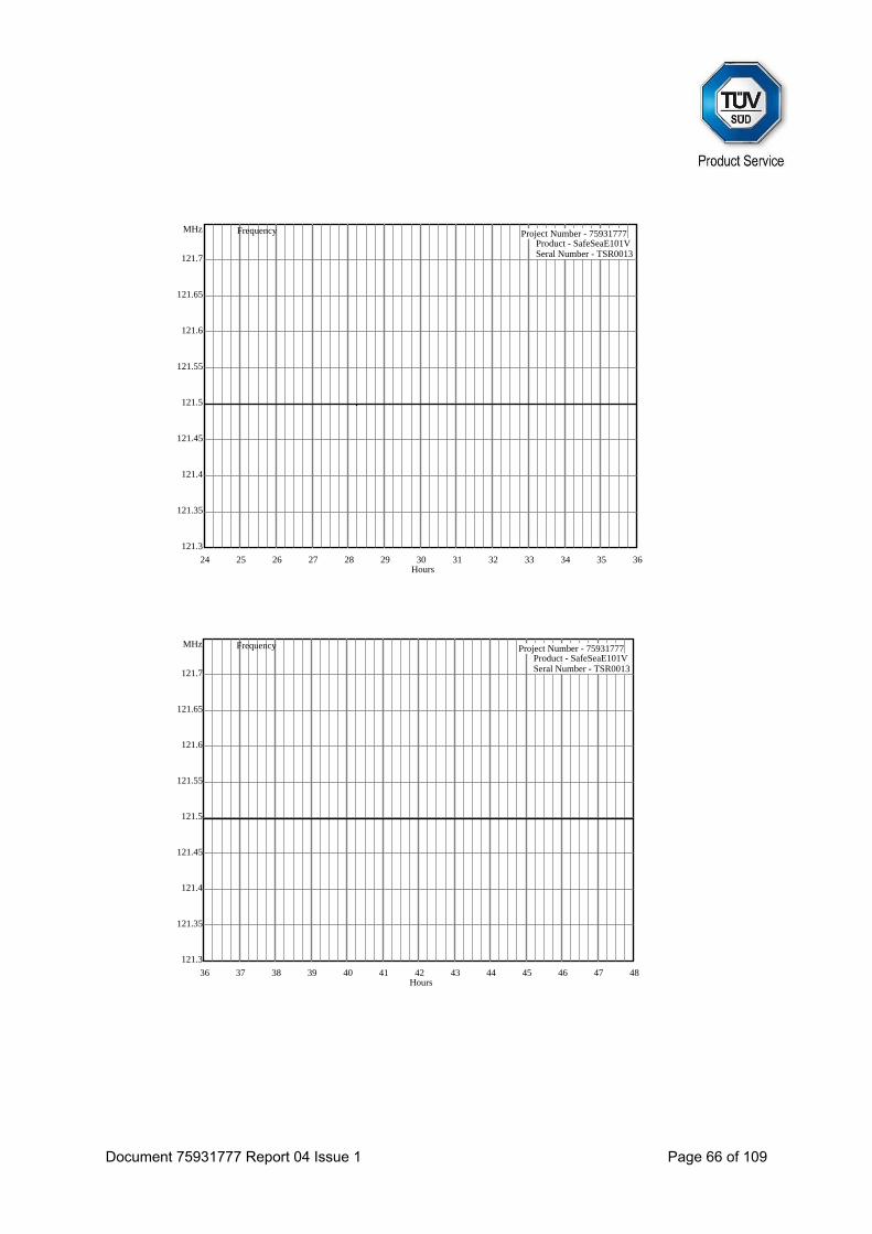
Document 75931777 Report 04 Issue 1 Page 66 of 109
24 25 26 27 28 29 30 31 32 33 34 35 36
121.3
121.35
121.4
121.45
121.5
121.55
121.6
121.65
121.7
Hours
MHz Frequency Project Number - 75931777Product - SafeSeaE101VSeral Number - TSR0013
36 37 38 39 40 41 42 43 44 45 46 47 48
121.3
121.35
121.4
121.45
121.5
121.55
121.6
121.65
121.7
Hours
MHz Frequency Project Number - 75931777Product - SafeSeaE101VSeral Number - TSR0013
Document 75931777 Report 04 Issue 1 Page 67 of 109
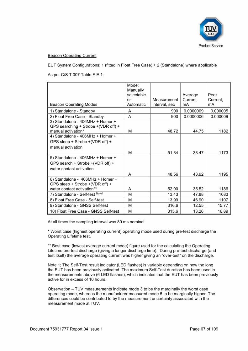
Beacon Operating Current
EUT System Configurations: 1 (fitted in Float Free Case) + 2 (Standalone) where applicable As per C/S T.007 Table F-E.1:
Beacon Operating Modes
Mode: Manually selectable or Automatic
Measurement interval, sec
Average Current, mA
Peak Current, mA
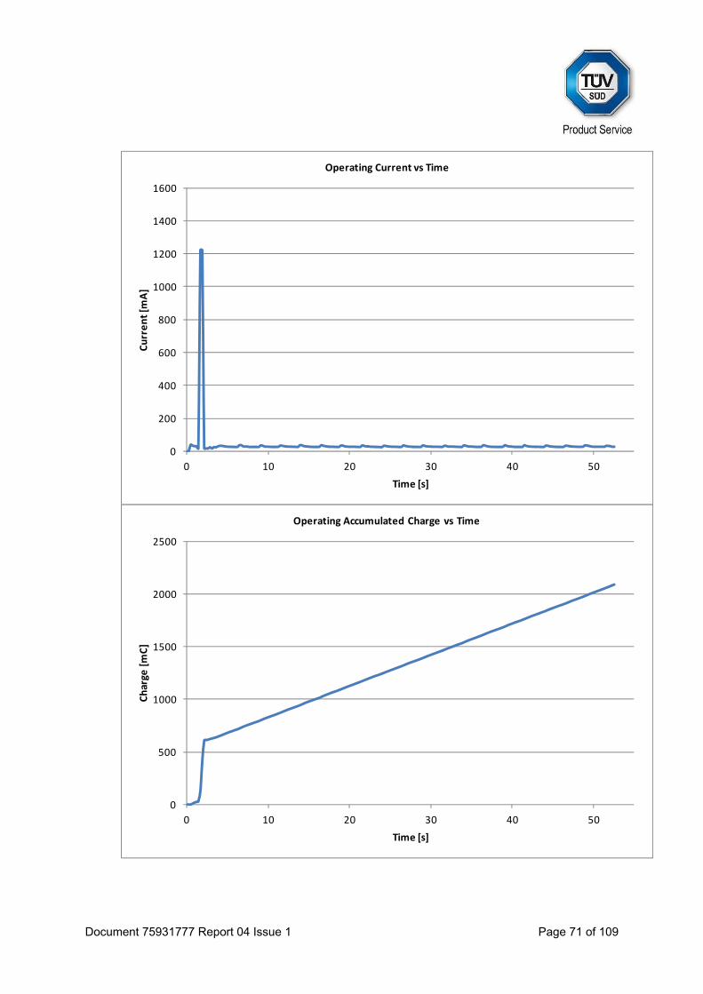
1) Standalone - Standby A 900 0.0000009 0.0000052) Float Free Case - Standby A 900 0.0000006 0.0000093) Standalone - 406MHz + Homer + GPS searching + Strobe +(VDR off) + manual activation* M 48.72 44.75 11824) Standalone - 406MHz + Homer + GPS sleep + Strobe +(VDR off) + manual activation M 51.84 38.47 11735) Standalone - 406MHz + Homer + GPS search + Strobe +(VDR off) + water contact activation A 48.56 43.92 11956) Standalone - 406MHz + Homer + GPS sleep + Strobe +(VDR off) + water contact activation** A 52.00 35.52 11867) Standalone - Self-test Note1 M 13.43 47.88 10838) Float Free Case - Self-test M 13.99 46.90 11079) Standalone - GNSS Self-test M 316.6 12.55 15.77
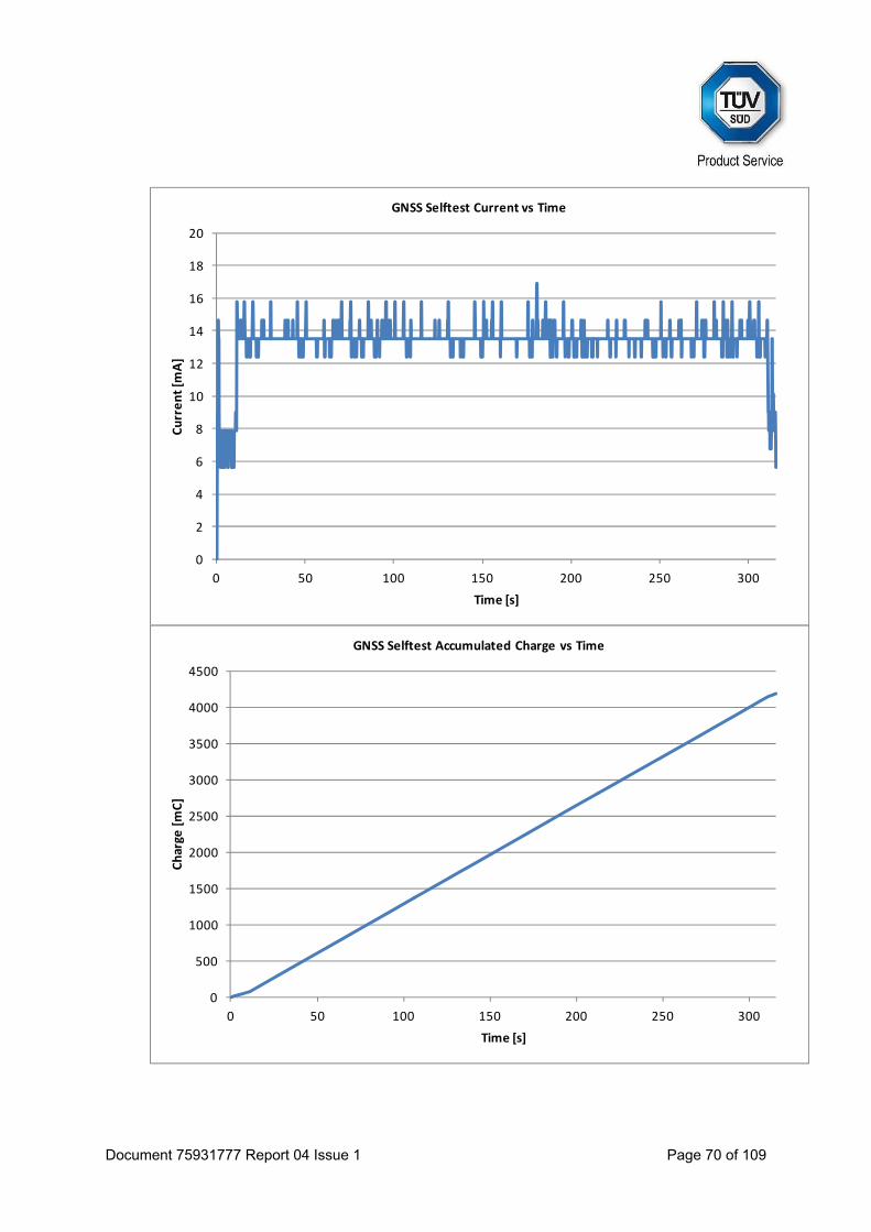
10) Float Free Case - GNSS Self-test M 315.6 13.26 16.89
At all times the sampling interval was 80 ms nominal. * Worst case (highest operating current) operating mode used during pre-test discharge the Operating Lifetime test. ** Best case (lowest average current mode) figure used for the calculating the Operating Lifetime pre-test discharge (giving a longer discharge time). During pre-test discharge (and test itself) the average operating current was higher giving an “over-test” on the discharge. Note 1; The Self-Test result indicator (LED flashes) is variable depending on how the long the EUT has been previously activated. The maximum Self-Test duration has been used in the measurements above (6 LED flashes), which indicates that the EUT has been previously active for in excess of 10 hours. Observation – TUV measurements indicate mode 3 to be the marginally the worst case operating mode, whereas the manufacturer measured mode 5 to be marginally higher. The differences could be contributed to by the measurement uncertainty associated with the measurement made at TUV.
Document 75931777 Report 04 Issue 1 Page 68 of 109
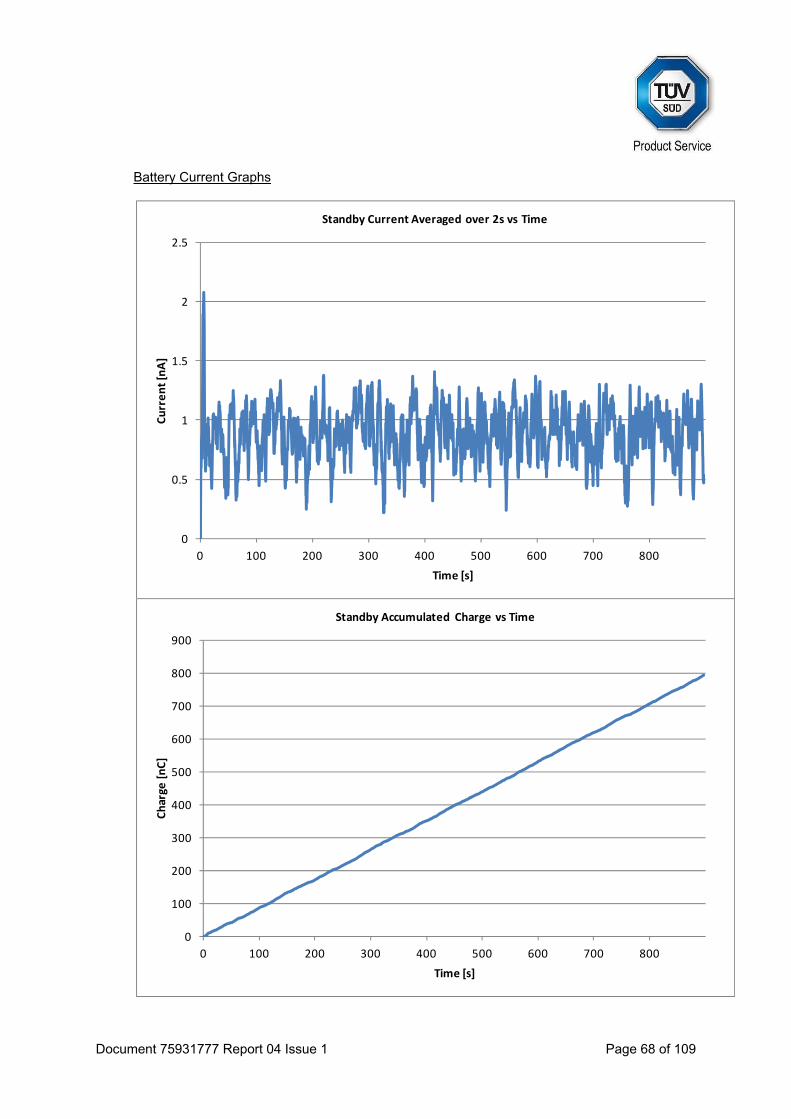
Battery Current Graphs
0
0.5
1
1.5
2
2.5
0 100 200 300 400 500 600 700 800
Current [nA]
Time [s]
Standby Current Averaged over 2s vs Time
0
100
200
300
400
500
600
700
800
900
0 100 200 300 400 500 600 700 800
Charge
[nC]
Time [s]
Standby Accumulated Charge vs Time
Document 75931777 Report 04 Issue 1 Page 69 of 109
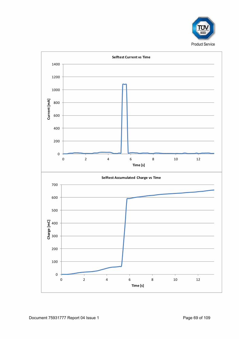
0
200
400
600
800
1000
1200
1400
0 2 4 6 8 10 12
Current [m
A]
Time [s]
Selftest Current vs Time
0
100
200
300
400
500
600
700
0 2 4 6 8 10 12
Charge
[mC]
Time [s]
Selftest Accumulated Charge vs Time
Document 75931777 Report 04 Issue 1 Page 70 of 109
0
2
4
6
8
10
12
14
16
18
20
0 50 100 150 200 250 300
Current [m
A]
Time [s]
GNSS Selftest Current vs Time
0
500
1000
1500
2000
2500
3000
3500
4000
4500
0 50 100 150 200 250 300
Charge
[mC]
Time [s]
GNSS Selftest Accumulated Charge vs Time
Document 75931777 Report 04 Issue 1 Page 71 of 109
0
200
400
600
800
1000
1200
1400
1600
0 10 20 30 40 50
Current [m
A]
Time [s]
Operating Current vs Time
0
500
1000
1500
2000
2500
0 10 20 30 40 50
Charge
[mC]
Time [s]
Operating Accumulated Charge vs Time
Document 75931777 Report 04 Issue 1 Page 72 of 109
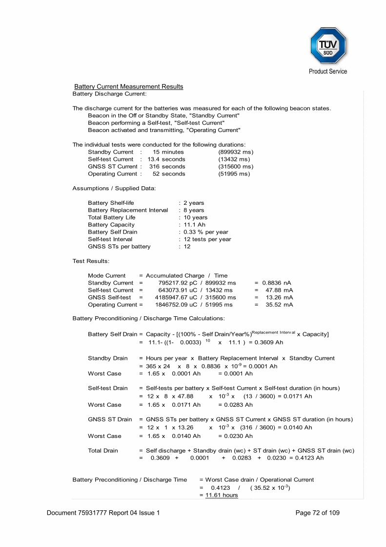
Battery Current Measurement Results
Standby Current :Self-test Current :GNSS ST Current :Operating Current :
:::::::
Mode Current =Standby Current = / =Self-test Current = / =GNSS Self-test = / =Operating Current = / =
Battery Self Drain =
= 10 x ) =
Standby Drain =
= 365 x 24 x 8 x x =Worst Case = x =
Self-test Drain =
= 12 x 8 x x x =
Worst Case = x =
GNSS ST Drain =
= 12 x 1 x x x =
Worst Case = x =
Total Drain == =
=
= /=
GNSS STs per battery 12
0.0230+
316 seconds (315600 ms)
GNSS STs per battery x GNSS ST Current x GNSS ST duration (in hours)
13.26 10-3 (316 / 3600) 0.0140 Ah
0.0033)
mA
12 tests per year
51995 ms
mA13432 ms
35.521846752.09 uC
0.0001 0.4123 Ah0.0283
Self-tests per battery x Self-test Current x Self-test duration (in hours)
4185947.67 uC 315600 ms 13.26 mA
0.0140 Ah 0.0230 Ah
11.61 hours
11.1
0.8836
Self discharge + Standby drain (wc) + ST drain (wc) + GNSS ST drain (wc)
0.0001 Ah10-9
47.88 10-3 (13
++
0.0171 Ah/ 3600)
0.3609
0.0171 Ah 0.0283 Ah
1.65
Battery Preconditioning / Discharge Time
Beacon activated and transmitting, "Operating Current"
x 10-3)
0.3609 Ah
Worst Case drain / Operational Current
Assumptions / Supplied Data:
0.0001 Ah 0.0001 Ah
0.33 % per year
1.65
Hours per year x Battery Replacement Interval x Standby Current
Accumulated Charge / Time
Total Battery LifeBattery CapacityBattery Self DrainSelf-test Interval
(899932 ms)
Battery Shelf-life 2 yearsBattery Replacement Interval 8 years
0.4123 ( 35.52
10 years11.1 Ah
11.1- ((1-
Battery Preconditioning / Discharge Time Calculations:
Capacity - [(100% - Self Drain/Year%)Replacement Interv al x Capacity]
643073.91 uC
Test Results:
795217.92 pC 899932 ms nA0.883647.88
(13432 ms)
1.65
Battery Discharge Current:
Beacon performing a Self-test, "Self-test Current"
The discharge current for the batteries was measured for each of the following beacon states.
13.4
52
seconds
seconds (51995 ms)
Beacon in the Off or Standby State, "Standby Current"
15The individual tests were conducted for the following durations:
minutes

Document 75931777 Report 04 Issue 1 Page 73 of 109
As per C/S T.007 Table F-E.2:
Characteristic Designation Units Value Comments Beacon manufacturers declare maximum allowed cell shelf-life (from date of cell manufacture to date of battery pack installation in the beacon)
TCS or TCS Years 2
Declared beacon battery replacement period (from date of manufacture)
TBR or TBR Years 8
Battery pack electrical configuration Three cells in Series Cell model and cell chemistry Ultralife U10013 Lithium Nominal cell capacity A-hrs 11.1 Nominal battery pack capacity CBN A-hrs 11.1 Annual battery cell capacity loss (self-discharge) due to aging, as specified by cell manufacturer at ambient temperature
LSDC % 0.33
Calculated battery pack capacity loss due to self-discharge: LCBN= CBN-[CBN*(1-LSDC/100)TBR+TCS]
LCBN A-hrs 0.3609
Number of self-tests per year NST 12 Average battery current during a self-test IST mA 47.88 Maximum duration of a self-test TST sec 13.5 Calculated battery pack loss due to self-tests during battery replacement period: LST= IST*TST*TBR*NST/3600
LST mA-hrs
17.2
Maximum number of GNSS self-tests between battery replacements
NGST 12
Average battery current during a GNSS self-test of maximum duration
IGST mA 13.26
Maximum duration of a GNSS self-test TGST sec 316 Calculated battery pack loss due to GNSS self-tests during battery replacement period: LGST= IGST*TGST*NGST/3600
LGST mA-hrs
13.96
Average battery standby current ISB mA 0.0000009
Other Capacity Losses LOTH mA-hrs
none
Battery pack capacity loss due to constant operation of circuitry prior to beacon activation: LISB = ISB*TBR*8760
LISB mA-hrs
0.063
Calculated value of the battery pack pre-test discharge: LCDC = LCBN +1.65*(LST+LGST+LISB)/1000+LOTH/1000
LCDC A-hrs 0.412
Test Summary The results indicate compliance with Cospas-Sarsat T.007, Clause A.2.3.
Document 75931777 Report 04 Issue 1 Page 74 of 109
2.8 FREQUENCY STABILITY TEST WITH TEMPERATURE GRADIENT
2.8.1 Specification
Cospas-Sarsat T.007, Clause A.2.4
2.8.2 Equipment Under Test and Modification State
E101V S/N: 0800002P - Modification State 0
2.8.3 Date of Test
13 October 2015
2.8.4 Test Equipment Used
The major items of test equipment used for the above tests are identified in Section 3.1.
2.8.5 Environmental Conditions
Ambient Temperature 21.4°C Relative Humidity 41.6%
Document 75931777 Report 04 Issue 1 Page 75 of 109
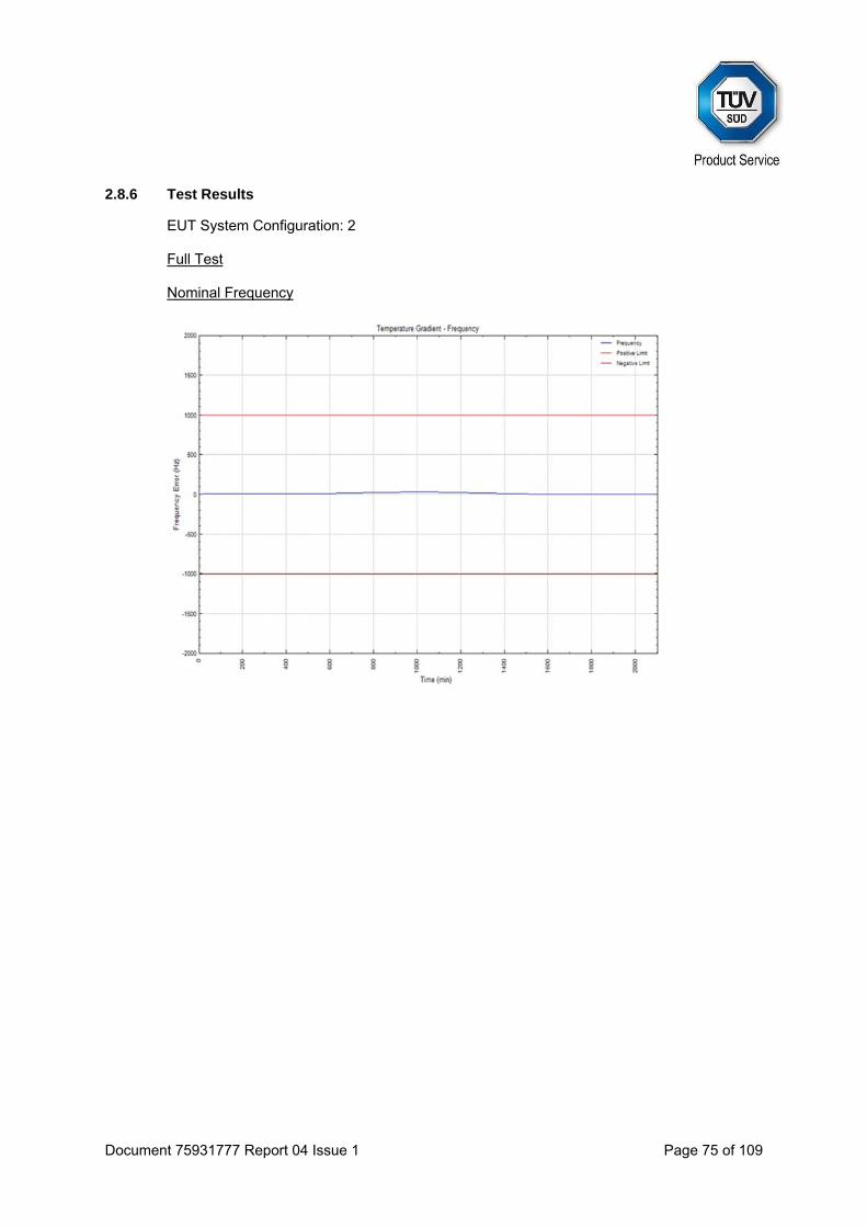
2.8.6 Test Results
EUT System Configuration: 2 Full Test Nominal Frequency
Document 75931777 Report 04 Issue 1 Page 76 of 109
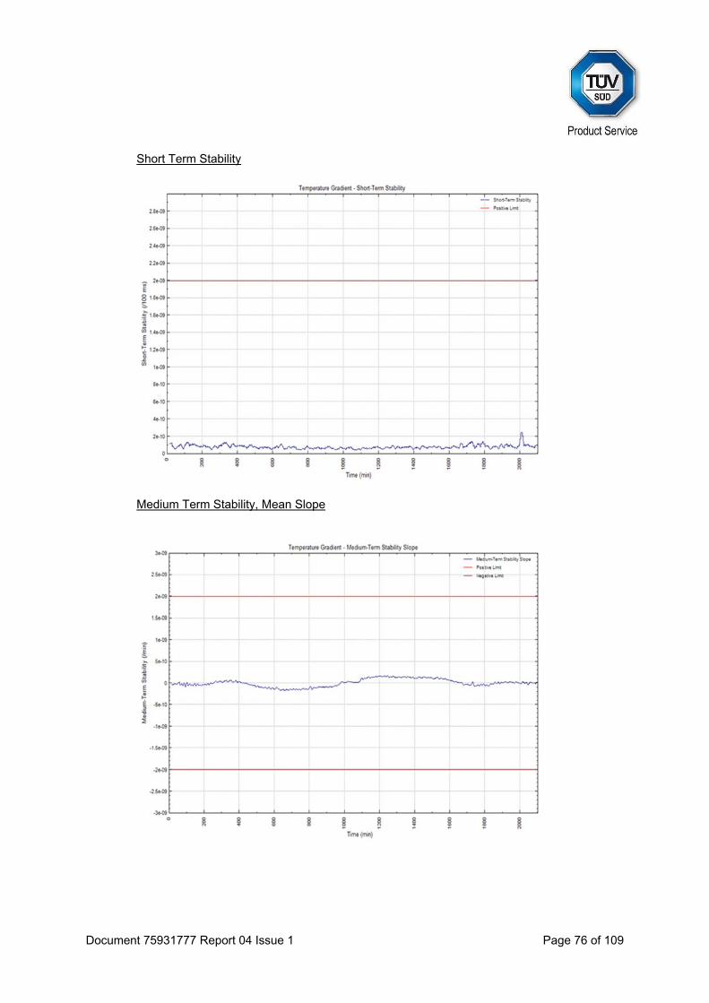
Short Term Stability
Medium Term Stability, Mean Slope
Document 75931777 Report 04 Issue 1 Page 77 of 109
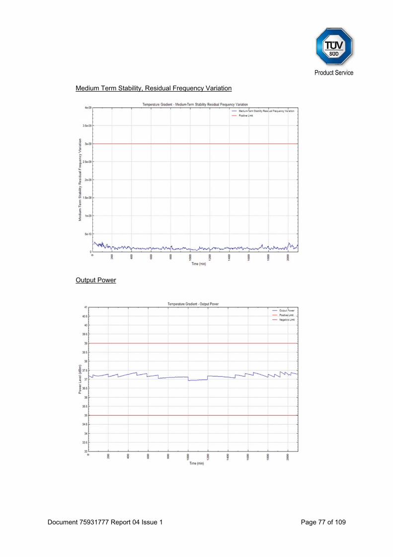
Medium Term Stability, Residual Frequency Variation
Output Power
Document 75931777 Report 04 Issue 1 Page 78 of 109
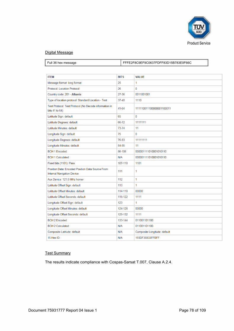
Digital Message
Full 36 hex message FFFE2F8C9EF9C0637FDFF83D15B783E0F66C
Test Summary The results indicate compliance with Cospas-Sarsat T.007, Clause A.2.4.
Document 75931777 Report 04 Issue 1 Page 79 of 109
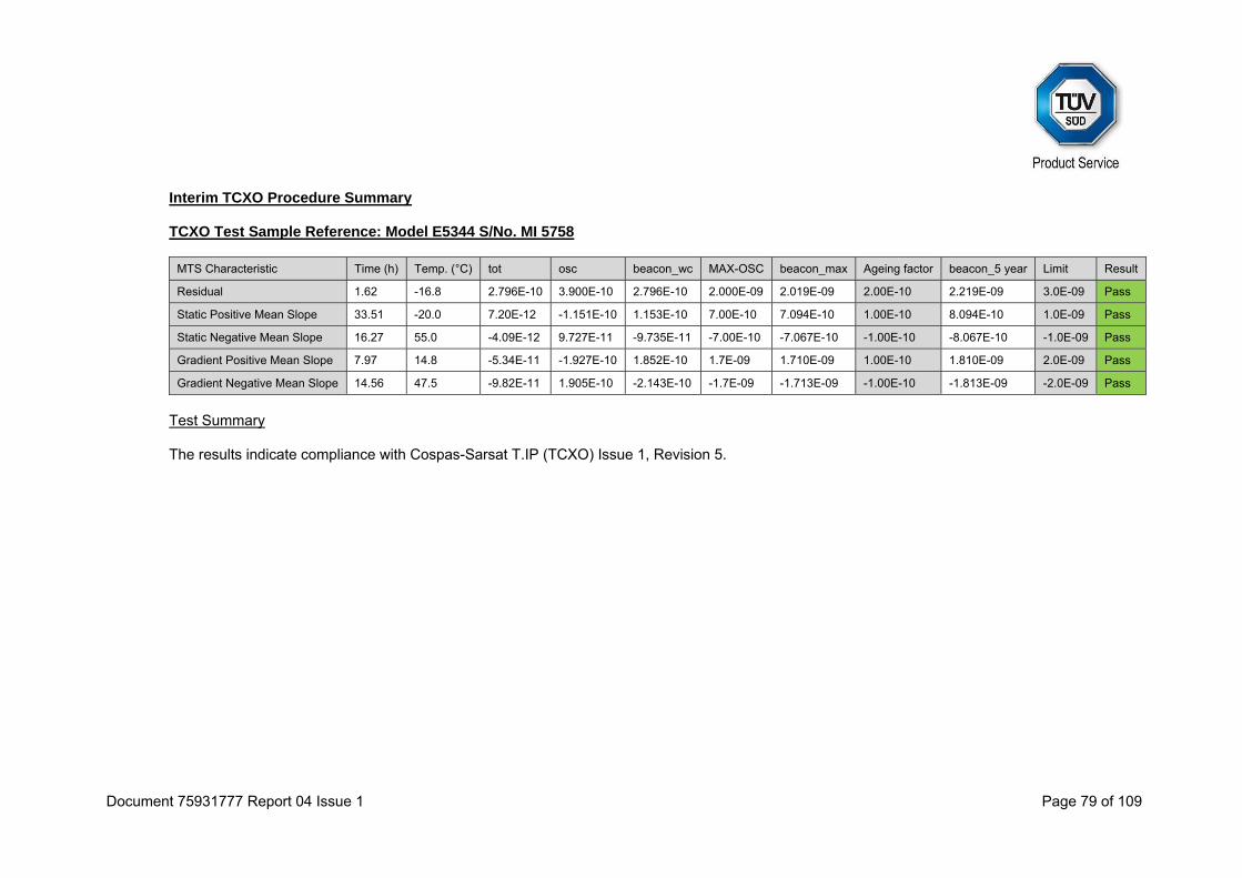
Interim TCXO Procedure Summary TCXO Test Sample Reference: Model E5344 S/No. MI 5758
MTS Characteristic Time (h) Temp. (°C) tot osc beacon_wc MAX-OSC beacon_max Ageing factor beacon_5 year Limit Result
Residual 1.62 -16.8 2.796E-10 3.900E-10 2.796E-10 2.000E-09 2.019E-09 2.00E-10 2.219E-09 3.0E-09 Pass
Static Positive Mean Slope 33.51 -20.0 7.20E-12 -1.151E-10 1.153E-10 7.00E-10 7.094E-10 1.00E-10 8.094E-10 1.0E-09 Pass
Static Negative Mean Slope 16.27 55.0 -4.09E-12 9.727E-11 -9.735E-11 -7.00E-10 -7.067E-10 -1.00E-10 -8.067E-10 -1.0E-09 Pass
Gradient Positive Mean Slope 7.97 14.8 -5.34E-11 -1.927E-10 1.852E-10 1.7E-09 1.710E-09 1.00E-10 1.810E-09 2.0E-09 Pass
Gradient Negative Mean Slope 14.56 47.5 -9.82E-11 1.905E-10 -2.143E-10 -1.7E-09 -1.713E-09 -1.00E-10 -1.813E-09 -2.0E-09 Pass
Test Summary The results indicate compliance with Cospas-Sarsat T.IP (TCXO) Issue 1, Revision 5.
Document 75931777 Report 04 Issue 1 Page 80 of 109
2.9 SATELLITE QUALITATIVE TESTS
2.9.1 Specification
Cospas-Sarsat T.007, Clause A.2.5
2.9.2 Equipment Under Test and Modification State
E101V S/N: 0800003P - Modification State 0
2.9.3 Date of Test
30 September 2015, 1 October 2015, 2 October 2015, 3 October 2015 & 6 October 2015
2.9.4 Test Equipment Used
The major items of test equipment used for the above tests are identified in Section 3.1.
2.9.5 Environmental Conditions
Ambient Temperature 9.8 - 18.3°C Relative Humidity 49.1 - 77.6%

Document 75931777 Report 04 Issue 1 Page 81 of 109
2.9.6 Test Results
EUT System Configuration: 2 Test Configuration 5 Test Start: 2015-10-02 17:22:58z Test End: 2015-10-03 07:27:46z 15 Hex ID: 193DF380C6FFBFF Actual location of the test beacon: (Daedalus Airfield, Lee-on-the-Solent, West)
50.818263 -1.197454
Satellite ID
Satellite Pass Number
15 Hex ID Provided by LUT
DopplerLatitude
Doppler Longitude
Mean Rx Power (dBm)
TCA CTA (deg)
LocationError (km)
S12 34257 193DF 380C6 FFBFF 50.80948 -1.19994 -127.25 01:16:01 -17.706 0.991 S12 34258 193DF 380C6 FFBFF 50.82247 -1.21563 -125.39 02:57:39 -1.691 1.359 S12 34259 193DF 380C6 FFBFF 50.81427 -1.19519 -125.66 04:37:50 12.973 0.471
S7 90409 193DF 380C6 FFBFF 50.80796 -1.20845 -126.27 05:04:18 -12.148 1.381 S10 53418 193DF 380C6 FFBFF 50.81829 -1.20114 -115.18 05:05:37 -10.068 0.259 S10 53419 193DF 380C6 FFBFF 50.80898 -1.19589 -126.55 06:46:30 5.515 1.037
S7 90410 193DF 380C6 FFBFF 50.81659 -1.19391 -116.88 06:44:30 3.493 0.311 S7 90417 193DF 380C6 FFBFF 50.83455 -1.18688 -125.40 18:10:06 -11.839 1.956
S10 53426 193DF 380C6 FFBFF 50.83429 -1.18268 -125.93 18:18:55 -15.728 2.061 S11 46456 193DF 380C6 FFBFF 50.82637 -1.20851 -127.05 19:01:29 15.580 1.189 S13 15772 193DF 380C6 FFBFF 50.83393 -1.22126 -128.42 19:55:46 8.622 2.413 S11 46457 193DF 380C6 FFBFF 50.82351 -1.18953 -126.70 20:40:46 1.439 0.806 S13 15773 193DF 380C6 FFBFF 50.83172 -1.19545 -128.61 21:35:46 -6.609 1.502 S11 46458 193DF 380C6 FFBFF 50.82183 -1.19459 -125.75 22:21:28 -14.366 0.444 S12 34271 193DF 380C6 FFBFF 50.80853 -1.19991 -131.05 01:04:31 -19.518 1.095 S12 34272 193DF 380C6 FFBFF 50.81569 -1.21629 -126.70 02:46:20 -3.461 1.353 S12 34273 193DF 380C6 FFBFF 50.81480 -1.19690 -126.26 04:26:41 11.448 0.387
S7 90423 193DF 380C6 FFBFF 50.80523 -1.19970 -126.89 04:39:10 -16.132 1.457 S10 53432 193DF 380C6 FFBFF 50.80568 -1.20393 -126.68 04:53:58 -11.943 1.470 S10 53433 193DF 380C6 FFBFF 50.81161 -1.18759 -127.89 06:35:01 3.790 1.013
Location Errors greater than 5 km are marked in red text. Ratio of Successful Solutions =
number of Doppler solutions within 5 km with 1°<CTA<21° number of satellite passes over test duration with 1°<CTA<21°
= 20
20 = 100%
Document 75931777 Report 04 Issue 1 Page 82 of 109
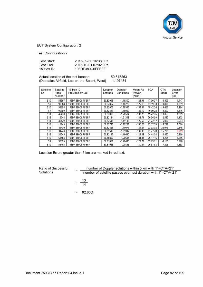
EUT System Configuration: 2
Test Configuration 7 Test Start: 2015-09-30 16:38:00z Test End: 2015-10-01 07:02:00z 15 Hex ID: 193DF380C6FFBFF Actual location of the test beacon: (Daedalus Airfield, Lee-on-the-Solent, West)
50.818263 -1.197454
Satellite ID
Satellite Pass Number
15 Hex ID Provided by LUT
DopplerLatitude
Doppler Longitude
Mean Rx Power (dBm)
TCA CTA (deg)
LocationError (km)
S10 53397 193DF 380C6 FFBFF 50.83098 -1.19300 -128.91 17:00:37 -3.409 1.447 S7 90388 193DF 380C6 FFBFF 50.82867 -1.18729 -129.18 17:19:33 -3.876 1.359
S10 53398 193DF 380C6 FFBFF 50.82606 -1.18596 -134.04 18:42:24 -19.467 1.184 S7 90389 193DF 380C6 FFBFF 50.82383 -1.18092 -135.19 19:00:28 -19.800 1.315
S11 46428 193DF 380C6 FFBFF 50.82878 -1.20584 -133.26 19:42:26 10.053 1.309 S13 15744 193DF 380C6 FFBFF 50.82124 -1.21348 -133.71 20:36:59 2.532 1.173 S11 46429 193DF 380C6 FFBFF 50.82545 -1.19145 -129.52 21:22:17 -5.000 0.903 S13 15745 193DF 380C6 FFBFF 50.82746 -1.19221 -136.23 22:17:35 -13.229 1.086 S11 46430 193DF 380C6 FFBFF 50.82458 -1.19075 -134.87 23:03:38 -20.976 0.845 S12 34243 193DF 380C6 FFBFF 50.81510 -1.05912 -139.36 01:27:28 -15.798 9.719 S12 34245 193DF 380C6 FFBFF 50.82147 -1.19610 -129.88 04:48:58 14.450 0.369 S10 53404 193DF 380C6 FFBFF 50.80850 -1.20644 -131.04 05:17:15 -8.204 1.255
S7 90395 193DF 380C6 FFBFF 50.81051 -1.20440 -129.79 05:29:21 -8.166 0.990 S10 53405 193DF 380C6 FFBFF 50.81063 -1.20815 -130.24 06:57:58 7.205 1.133
Location Errors greater than 5 km are marked in red text. Ratio of Successful Solutions =
number of Doppler solutions within 5 km with 1°<CTA<21° number of satellite passes over test duration with 1°<CTA<21°
= 13
14 = 92.86%

Document 75931777 Report 04 Issue 1 Page 83 of 109
EUT System Configuration: 2
Test Configuration 8 Test Start: 2015-10-01 17:21:01z Test End: 2015-10-02 07:22:29z 15 Hex ID: 193DF380C6FFBFF Actual location of the test beacon: (Daedalus Airfield, Lee-on-the-Solent, West)
50.818263 -1.197454
Satellite ID
Satellite Pass Number
15 Hex ID Provided by LUT
DopplerLatitude
Doppler Longitude
Mean Rx Power (dBm)
TCA CTA (deg)
LocationError (km)
S7 90403 193DF 380C6 FFBFF 50.82963 -1.18817 -125.61 18:35:14 -15.824 1.421 S11 46442 193DF 380C6 FFBFF 50.82730 -1.20716 -125.81 19:21:56 12.885 1.214 S13 15757 193DF 380C6 FFBFF 50.82082 -1.20339 -125.56 18:37:27 18.943 0.504 S13 15758 193DF 380C6 FFBFF 50.82835 -1.20794 -126.38 20:16:21 5.618 1.341 S13 15759 193DF 380C6 FFBFF 50.82506 -1.18801 -129.59 21:56:38 -9.913 1.005 S11 46443 193DF 380C6 FFBFF 50.75567 -0.49030 -115.62 21:01:27 -2.167 50.165 S10 53412 193DF 380C6 FFBFF 50.82547 -1.28349 -123.79 18:30:39 -17.538 6.093 S11 46444 193DF 380C6 FFBFF 50.81534 -1.13018 -117.82 22:42:31 -17.722 4.734 S12 34257 193DF 380C6 FFBFF 50.80948 -1.19994 -127.25 01:16:01 -17.706 0.991 S12 34258 193DF 380C6 FFBFF 50.82247 -1.21563 -125.39 02:57:39 -1.691 1.359 S12 34259 193DF 380C6 FFBFF 50.81427 -1.19519 -125.66 04:37:50 12.973 0.471
S7 90409 193DF 380C6 FFBFF 50.80796 -1.20845 -126.27 05:04:18 -12.148 1.381 S10 53418 193DF 380C6 FFBFF 50.81829 -1.20114 -115.18 05:05:37 -10.068 0.259 S10 53419 193DF 380C6 FFBFF 50.80898 -1.19589 -126.55 06:46:30 5.515 1.037
S7 90410 193DF 380C6 FFBFF 50.81659 -1.19391 -116.88 06:44:30 3.493 0.311
Location Errors greater than 5 km are marked in red text. Ratio of Successful Solutions =
number of Doppler solutions within 5 km with 1°<CTA<21° number of satellite passes over test duration with 1°<CTA<21°
= 13
15 = 86.66% Test Summary The results indicate compliance with Cospas-Sarsat T.007, Clause A.2.5.
Document 75931777 Report 04 Issue 1 Page 84 of 109
2.10 BEACON ANTENNA TEST
2.10.1 Specification
Cospas-Sarsat T.007, Clause A.2.6
2.10.2 Equipment Under Test and Modification State
E101V S/N: 0800003P - Modification State 0
2.10.3 Date of Test
10 September 2015
2.10.4 Test Equipment Used
The major items of test equipment used for the above tests are identified in Section 3.1.
2.10.5 Environmental Conditions
Ambient Temperature 18.8 – 20.2°C Relative Humidity 52 - 58%
2.10.6 Test Results
EUT System Configuration: 2 Note: Measurements were made using a dipole antenna in a fully screened semi-anechoic chamber.

Document 75931777 Report 04 Issue 1 Page 85 of 109
Test Configuration 1 (B.4)
Elevation Angle (degrees)
10 20 30 40 50
Azimuth Angle(Degrees)
EIRP dBm
Ant dBi
EIRP dBm
Ant dBi
EIRPdBm
Ant dBi
EIRPdBm
Ant dBi
EIRP dBm
AntdBi
0 38.8 1.5 41.0 3.8 42.8 5.6 39.3 2.1 33.6 -3.6
30 38.7 1.5 41.0 3.8 42.7 5.5 39.0 1.8 33.5 -3.7
60 38.8 1.6 40.9 3.7 42.6 5.4 39.0 1.8 33.7 -3.5
90 38.9 1.6 41.1 3.8 42.8 5.5 39.0 1.8 33.6 -3.6
120 38.9 1.6 40.9 3.7 42.6 5.4 39.0 1.8 33.6 -3.7
150 38.8 1.6 41.0 3.8 42.8 5.6 39.0 1.8 33.8 -3.4
180 38.8 1.6 41.0 3.8 42.7 5.4 39.0 1.8 33.6 -3.6
210 38.8 1.5 41.0 3.8 42.7 5.5 39.2 2.0 33.5 -3.7
240 38.6 1.3 41.3 4.0 42.7 5.5 39.2 2.0 33.9 -3.3
270 38.8 1.6 41.1 3.9 42.6 5.4 39.3 2.0 34.2 -3.1
300 38.7 1.5 41.2 4.0 42.8 5.6 39.3 2.1 33.8 -3.4
330 38.7 1.5 41.1 3.8 42.7 5.4 39.3 2.1 33.9 -3.3
Elevation Angle (degrees)
10 20 30 40 50
Azimuth Angle(Degrees)
Vv Vh Vv Vh Vv Vh Vv Vh Vv Vh
0 110.4 88.2 112.3 88.1 113.4 88.9 108.8 90.5 101.6 72.7
30 110.4 84.5 112.3 87.8 113.3 89.8 108.5 92.0 101.5 80.4
60 110.5 87.6 112.2 88.0 113.2 88.3 108.5 90.4 101.7 69.3
90 110.5 86.7 112.3 85.9 113.3 88.3 108.5 90.9 101.6 77.3
120 110.6 87.0 112.2 87.2 113.2 89.4 108.5 90.5 101.5 77.3
150 110.5 87.9 112.3 87.0 113.4 89.2 108.5 91.3 101.8 79.3
180 110.5 84.2 112.3 89.3 113.2 91.3 108.5 91.3 101.6 80.1
210 110.4 88.6 112.3 85.6 113.3 88.8 108.7 90.2 101.5 79.9
240 110.3 82.6 112.5 88.9 113.3 90.3 108.6 91.5 101.9 80.0
270 110.5 87.4 112.4 87.3 113.2 89.2 108.7 90.7 102.1 78.9
300 110.4 85.7 112.5 89.7 113.4 91.0 108.7 91.4 101.8 76.7
330 110.4 87.7 112.3 86.9 113.2 89.4 108.8 92.4 101.9 80.3
Min (Vv-Vh) 21.8 22.8 21.9 16.4 21.1
Limit: 10
EIRPLOSS = Ptambient - PtEOL = 37.23 - 36.42 = 0.81 dB
EIRPmaxEOL = Max[EIRPmax, (EIRPmax - EIRPLOSS)] = Max[ 42.8, 42.0 ]= 42.8 dBm
EIRPminEOL = Min[EIRPmin, (EIRPmin - EIRPLOSS)] = Min[ 33.5, 32.7 ]= 32.7 dBm

Document 75931777 Report 04 Issue 1 Page 86 of 109
Test Configuration 4 (B.5)
Elevation Angle (degrees)
10 20 30 40 50
Azimuth Angle(Degrees)
EIRP dBm
Ant dBi
EIRP dBm
Ant dBi
EIRPdBm
Ant dBi
EIRPdBm
Ant dBi
EIRP dBm
AntdBi
0 37.7 0.5 40.8 3.6 36.7 -0.5 32.1 -5.2 31.4 -5.8
90 38.8 1.6 41.2 4.0 38.2 1.0 33.5 -3.7 29.2 -8.0
180 39.6 2.4 41.2 4.0 38.4 1.2 33.2 -4.1 19.5 -17.7
270 39.7 2.5 41.3 4.0 39.1 1.9 32.4 -4.8 20.0 -17.3
EIRPLOSS = Ptambient - PtEOL = 37.23 - 36.42 = 0.81 dB
EIRPmaxEOL = Max[EIRPmax, (EIRPmax - EIRPLOSS)] = Max[ 41.3, 40.5 ]= 41.3dBm
EIRPminEOL = Min[EIRPmin, (EIRPmin - EIRPLOSS)] = Min[ 31.4, 30.6 ]= 30.6dBm Test Summary The results indicate compliance with Cospas-Sarsat T.007, Clause A.2.6.
Document 75931777 Report 04 Issue 1 Page 87 of 109
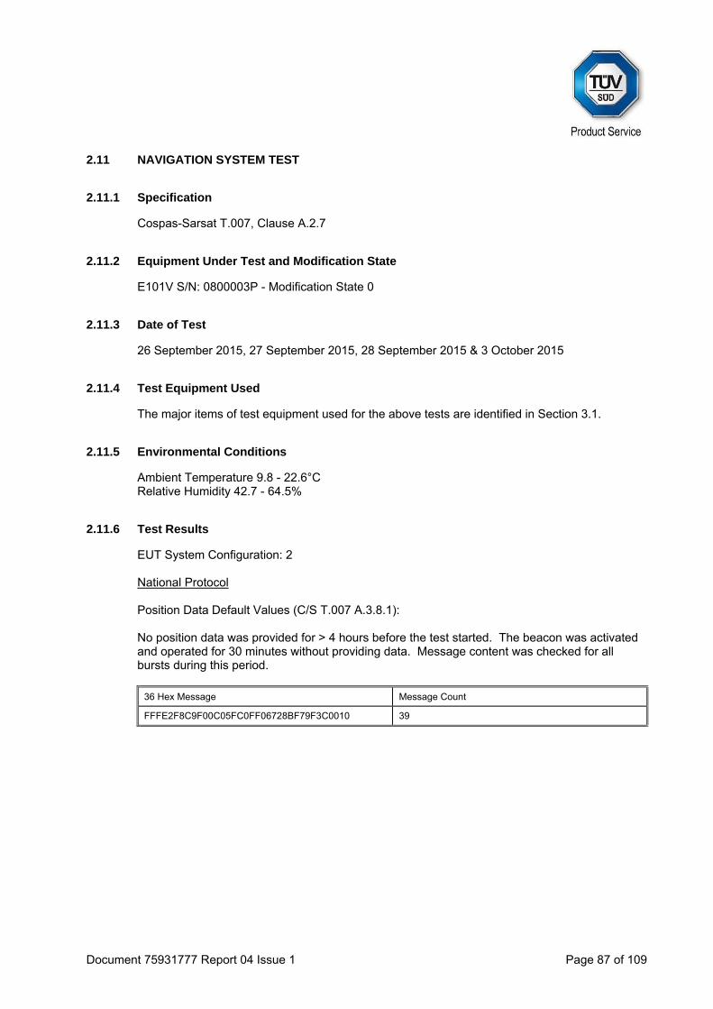
2.11 NAVIGATION SYSTEM TEST
2.11.1 Specification
Cospas-Sarsat T.007, Clause A.2.7
2.11.2 Equipment Under Test and Modification State
E101V S/N: 0800003P - Modification State 0
2.11.3 Date of Test
26 September 2015, 27 September 2015, 28 September 2015 & 3 October 2015
2.11.4 Test Equipment Used
The major items of test equipment used for the above tests are identified in Section 3.1.
2.11.5 Environmental Conditions
Ambient Temperature 9.8 - 22.6°C Relative Humidity 42.7 - 64.5%
2.11.6 Test Results
EUT System Configuration: 2 National Protocol Position Data Default Values (C/S T.007 A.3.8.1):
No position data was provided for > 4 hours before the test started. The beacon was activated and operated for 30 minutes without providing data. Message content was checked for all bursts during this period.
36 Hex Message Message Count
FFFE2F8C9F00C05FC0FF06728BF79F3C0010 39
Document 75931777 Report 04 Issue 1 Page 88 of 109
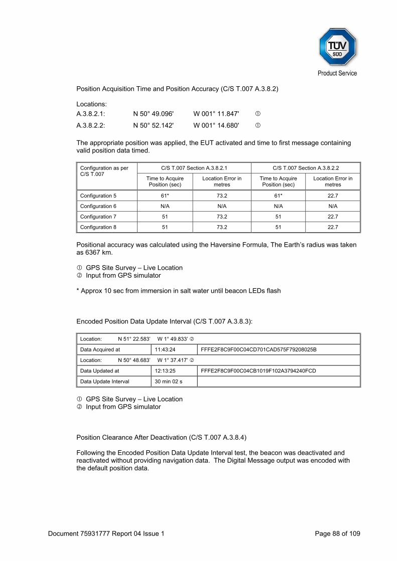
Position Acquisition Time and Position Accuracy (C/S T.007 A.3.8.2)
Locations:
A.3.8.2.1: N 50° 49.096' W 001° 11.847'
A.3.8.2.2: N 50° 52.142' W 001° 14.680'
The appropriate position was applied, the EUT activated and time to first message containing valid position data timed.
Configuration as per C/S T.007
C/S T.007 Section A.3.8.2.1 C/S T.007 Section A.3.8.2.2
Time to Acquire Position (sec)
Location Error in metres
Time to Acquire Position (sec)
Location Error in metres
Configuration 5 61* 73.2 61* 22.7
Configuration 6 N/A N/A N/A N/A
Configuration 7 51 73.2 51 22.7
Configuration 8 51 73.2 51 22.7
Positional accuracy was calculated using the Haversine Formula, The Earth’s radius was taken as 6367 km.
GPS Site Survey – Live Location Input from GPS simulator
* Approx 10 sec from immersion in salt water until beacon LEDs flash
Encoded Position Data Update Interval (C/S T.007 A.3.8.3):
Location: N 51° 22.583’ W 1° 49.833’
Data Acquired at 11:43:24 FFFE2F8C9F00C04CD701CAD575F79208025B
Location: N 50° 48.683’ W 1° 37.417’
Data Updated at 12:13:25 FFFE2F8C9F00C04CB1019F102A3794240FCD
Data Update Interval 30 min 02 s
GPS Site Survey – Live Location Input from GPS simulator
Position Clearance After Deactivation (C/S T.007 A.3.8.4)
Following the Encoded Position Data Update Interval test, the beacon was deactivated and reactivated without providing navigation data. The Digital Message output was encoded with the default position data.
Document 75931777 Report 04 Issue 1 Page 89 of 109
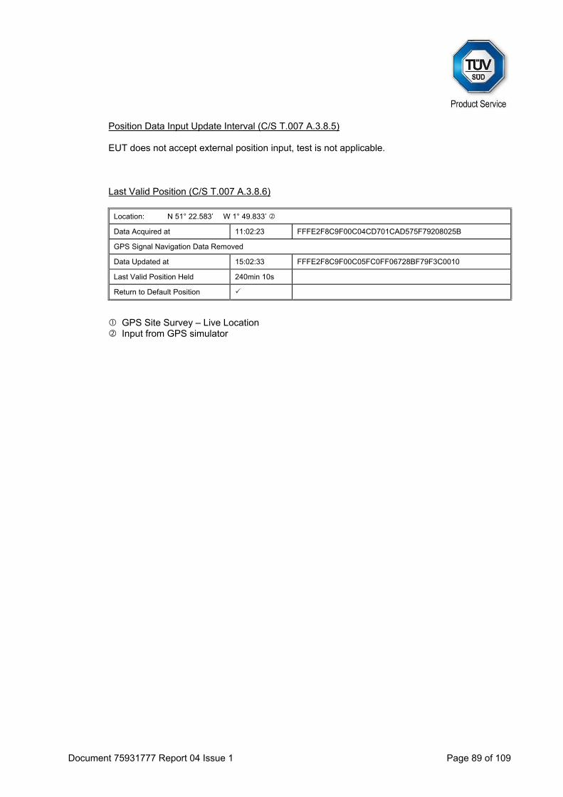
Position Data Input Update Interval (C/S T.007 A.3.8.5)
EUT does not accept external position input, test is not applicable.
Last Valid Position (C/S T.007 A.3.8.6)
Location: N 51° 22.583’ W 1° 49.833’
Data Acquired at 11:02:23 FFFE2F8C9F00C04CD701CAD575F79208025B
GPS Signal Navigation Data Removed
Data Updated at 15:02:33 FFFE2F8C9F00C05FC0FF06728BF79F3C0010
Last Valid Position Held 240min 10s
Return to Default Position
GPS Site Survey – Live Location Input from GPS simulator

Document 75931777 Report 04 Issue 1 Page 90 of 109
Standard Protocol Position Data Default Values (C/S T.007 A.3.8.1):
No position data was provided for > 4 hours before the test started. The beacon was activated and operated for 30 minutes without providing data. Message content was checked for all bursts during this period.
36 Hex Message Message Count
FFFE2F8C9EF9C0637FDFF83D15B783E0F66C 41
Position Acquisition Time and Position Accuracy (C/S T.007 A.3.8.2)
Locations:
A.3.8.2.1: N 50° 49.096' W 001° 11.847'
A.3.8.2.2: N 50° 52.142' W 001° 14.680'
The appropriate position was applied, the EUT activated and time to first message containing valid position data timed.
Configuration as per C/S T.007
C/S T.007 Section A.3.8.2.1 C/S T.007 Section A.3.8.2.2
Time to Acquire Position (sec)
Location Error in metres
Time to Acquire Position (sec)
Location Error in metres
Configuration 5 61* 73.2 61* 22.7
Configuration 6 N/A N/A N/A N/A
Configuration 7 51 73.2 51 22.7
Configuration 8 51 73.2 51 22.7
Positional accuracy was calculated using the Haversine Formula, The Earth’s radius was taken as 6367 km.
GPS Site Survey – Live Location Input from GPS simulator
* Approx 10 sec from immersion in salt water until beacon LEDs flash
Encoded Position Data Update Interval (C/S T.007 A.3.8.3):
Location: N 51° 22.583’ W 1° 49.833’
Data Acquired at 11:03:00 FFFE2F8C9EF9C06333A03ECA66771DA4D4D0
Location: N 50° 48.683’ W 1° 37.417’
Data Updated at 11:33:02 FFFE2F8C9EF9C06332E0311EC7778EA76951
Data Update Interval 30 min 02 s

Document 75931777 Report 04 Issue 1 Page 91 of 109
GPS Site Survey – Live Location Input from GPS simulator
Position Clearance After Deactivation (C/S T.007 A.3.8.4)
Following the Encoded Position Data Update Interval test, the beacon was deactivated and reactivated without providing navigation data. The Digital Message output was encoded with the default position data.
Position Data Input Update Interval (C/S T.007 A.3.8.5)
EUT does not accept external position input, test is not applicable.
Last Valid Position (C/S T.007 A.3.8.6)
Location: N 51° 22.583’ W 1° 49.833’
Data Acquired at 14:00:50 FFFE2F8C9EF9C06333A03ECA66771DA4D4D0
GPS Signal Navigation Data Removed
Data Updated at 18:01:00 FFFE2F8C9EF9C0637FDFF83D15B783E0F66C
Last Valid Position Held 240min 10s
Return to Default Position
GPS Site Survey – Live Location Input from GPS simulator

Document 75931777 Report 04 Issue 1 Page 92 of 109
User Protocol Position Data Default Values (C/S T.007 A.3.8.1):
No position data was provided for > 4 hours before the test started. The beacon was activated and operated for 30 minutes without providing data. Message content was checked for all bursts during this period.
36 Hex Message Message Count
FFFE2FCC9E0A000C607CEDF5BA2FE0FF0146 38
Position Acquisition Time and Position Accuracy (C/S T.007 A.3.8.2)
Locations:
A.3.8.2.1: N 50° 49.096' W 001° 11.847'
A.3.8.2.2: N 50° 52.142' W 001° 14.680'
The appropriate position was applied, the EUT activated and time to first message containing valid position data timed.
Configuration as per C/S T.007
C/S T.007 Section A.3.8.2.1 C/S T.007 Section A.3.8.2.2
Time to Acquire Position (sec)
Location Error in metres
Time to Acquire Position (sec)
Location Error in metres
Configuration 5 61* 2037.3 61* 1565.4
Configuration 6 N/A N/A N/A N/A
Configuration 7 51 2037.3 51 1565.4
Configuration 8 51 2037.3 51 1565.4
Positional accuracy was calculated using the Haversine Formula, The Earth’s radius was taken as 6367 km.
GPS Site Survey – Live Location Input from GPS simulator
* Approx 10 sec from immersion in salt water until beacon LEDs flash

Document 75931777 Report 04 Issue 1 Page 93 of 109
Encoded Position Data Update Interval (C/S T.007 A.3.8.3):
Location: N 51° 22.583’ W 1° 49.833’
Data Acquired at 12:26:37 FFFE2FCC9E0A000C607CEDF5BA266D01C026
Location: N 50° 48.683’ W 1° 37.417’
Data Updated at 12:56:39 FFFE2FCC9E0A000C607CEDF5BA265901967F
Data Update Interval 30 min 02 s
GPS Site Survey – Live Location Input from GPS simulator
Position Clearance After Deactivation (C/S T.007 A.3.8.4)
Following the Encoded Position Data Update Interval test, the beacon was deactivated and reactivated without providing navigation data. The Digital Message output was encoded with the default position data.
Position Data Input Update Interval (C/S T.007 A.3.8.5)
EUT does not accept external position input, test is not applicable.
Last Valid Position (C/S T.007 A.3.8.6)
Location: N 51° 22.583’ W 1° 49.833’
Data Acquired at 09:12:28 FFFE2FCC9E0A000C607CEDF5BA266D01C026
GPS Signal Navigation Data Removed
Data Updated at 13:12:38 FFFE2FCC9E0A000C607CEDF5BA2FE0FF0146
Last Valid Position Held 240min 10s
Return to Default Position
GPS Site Survey – Live Location Input from GPS simulator
Test Summary The results indicate compliance with Cospas-Sarsat T.007, Clause A.2.7.