report on oberoi slpendor residential ii &...
TRANSCRIPT
L&T ECC DIVISION
Report on Oberoi Slpendor Residential II & Commercial I (Summer Training)
At JVLR, Mumbai
Guided By R.M.Desai Project Manager, Oberoi Splendor
IV Semester, Department of Civil Engineering (B.Tech), V.N.I.T Nagpur
Submitted By Ruhi Thakur

P a g e 2 | 39
CERTIFICATE
This is to certify that Ms.Ruhi Thakur has successfully completed her summer training in our
organization from 10th May 2011 to 5th July 2011 during the academic year 2010-2011.
She was trained on site for the project “Oberoi Splendor- Residential II and Commercial I” under
the mentorship of Mr.R.M.Desai (Project Manager). Her overall performance during the period was
good.
R.M.Desai
Project Manager
(Oberoi Splendor)
July,2011

P a g e 3 | 39
ACKNOWLEGMENT
I extend my heartfelt gratitude and thanks to Mr R.M.Desai, Project Manager(L&T ECC) and Mr.SENTHIL
NATHAN(Planning Manager) for their valuable guidance, constructive suggestions and encouragement
throughout the training. I express a deep sense of gratitude and sincere thanks to the staff on site for their
constant support throughout the internship.
I express a deep sense of gratitude and sincere thanks to Mr.Lotkar(site-in-charge,Oberoi Residential Tower,
Grande), Mr.Sudhakar (Site-in-charge, Oberoi Commercial Tower, Prisma), Mr.Avinash Yadav, Mr. Amogh
Bhave, Mr.Ashish Thakur, Mr. Obaid Sayed, Mr. Anand Naigaonkar, Mr. Vanaraj, for their guidance, valuable
suggestions, unfailing support and channelling our efforts in the right direction throughout the progress of
this internship without which this would not have attained the present form.
I would also like to acknowledge the moral support of all other colleagues. I am in debt to all those people
who have directly or indirectly helped me during the internship.
IV semester, Civil Engineering (B.Tech)
Visvesvaraya National Institute Of Technology, Nagpur

P a g e 4 | 39
Contents CERTIFICATE ..........................................................................................................................................................2
ACKNOWLEGMENT ...............................................................................................................................................3
LIST OF FIGURES ...................................................................................................................................................5
OVERVIEW ............................................................................................................................................................6
PROJECT DETAIL ....................................................................................................................................................7
DETAILS OF TOWER GRANDE: ..........................................................................................................................8
DETAILS OF TOWER PRISMA: ............................................................................................................................9
CONTRACT DETAILS ........................................................................................................................................... 12
WORK ORDER FOR TOWER GRANDE ............................................................................................................. 12
WORK ORDER FOR TOWER PRISMA .............................................................................................................. 14
PROJECT PLANNING ........................................................................................................................................... 16
CONSTRUCTION MATERIALS ............................................................................................................................. 18
FORMWORKS ................................................................................................................................................. 18
Aluminium Formwork System ................................................................................................................... 18
DOKA FORMWORK SYSTEM ...................................................................................................................... 20
CLIMBING FORMWORK SYSYTEM ............................................................................................................. 22
CONCRETE...................................................................................................................................................... 25
ADMIXTURES ................................................................................................................................................. 26
STEEL .............................................................................................................................................................. 26
BAR BENDING YARD................................................................................................................................... 26
REINFORCEMENTS ..................................................................................................................................... 27
CEMENT AND ITS ADMIXTURES ..................................................................................................................... 27
Cement SBR Bonding Admixtures.............................................................................................................. 27
GYPSUM ......................................................................................................................................................... 28
BLOCKWORK .................................................................................................................................................. 28
METHOD OF CONSTRUCTIONS .......................................................................................................................... 29
MIVAN FORMWORK ...................................................................................................................................... 29
BLOCKWORK .................................................................................................................................................. 30
WATER PROOFING ......................................................................................................................................... 31
GYPSUM PLASTERING .................................................................................................................................... 31
EXTERNAL PLASTERING ................................................................................................................................. 32
DOOR FIXING ................................................................................................................................................. 33
BATCHING PLANT .............................................................................................................................................. 34

P a g e 5 | 39
CONSTRUCTIONAL PROBLEMS AND DISCOVERIES ............................................................................................ 36
QUALITY MANAGEMENT SYSTEM ..................................................................................................................... 37
HEALTH, SAFETY AND ENIVIRONMENT SYSTEM................................................................................................ 38
BIBLIOGRAPHY ................................................................................................................................................... 39
LIST OF FIGURES
Figure 1 Tower Grande Modular View .................................................................................................................8
Figure 2 : PRISMA Modelur View ..........................................................................................................................9
Figure 3: Aluminium Formwork ......................................................................................................................... 18
Figure 4: Aluminium Formwork ......................................................................................................................... 19
Figure 5: Circular formwork for the column ...................................................................................................... 20
Figure 6: H-Beams laid for first floor slab .......................................................................................................... 20
Figure 7: H Beam ............................................................................................................................................... 20
Figure 8: H Beam ................................................................................................... Error! Bookmark not defined.
Figure 9: Cross Section H Beam H-16/H-20 ....................................................................................................... 21
Figure 10: Climbing Formwork .......................................................................................................................... 22
Figure 11: Structure of climbing formwork ....................................................................................................... 22
Figure 12: Climbing formwork ........................................................................................................................... 23
Figure 13: Concrete being poured in the column formwork and the Reinforcement ...................................... 25
Figure 14: Concrete being poured in the column formwork and the Reinforcement ...................................... 25
Figure 15: Bar Bending Yard .............................................................................................................................. 26
Figure 16: Top Vied of Reinforcement on podium 2 ......................................................................................... 27
Figure 17: Blockwork ......................................................................................................................................... 28
Figure 18: Mivan Assembly ................................................................................................................................ 29
Figure 19: Setup of formwork ........................................................................................................................... 29
Figure 20: Laying of Blockwork .......................................................................................................................... 30
Figure 21: Mesh fixed at junctions .................................................................................................................... 32
Figure 22: RCC being chiselled ........................................................................................................................... 32
Figure 23: Door attached to the frame ............................................................................................................. 33
Figure 24: Door Frame being fixed .................................................................................................................... 33
Figure 25: Schematic presentation of Concrete Production ............................................................................. 34
Figure 27: Batching Plant Controls .................................................................................................................... 34
Figure 28: Concrete Cubes for testing ............................................................................................................... 34
Figure 26: Conveyor Belt ................................................................................................................................... 34

P a g e 6 | 39
OVERVIEW Larsen & Toubro Limited (L&T) is India's largest engineering and construction conglomerate with additional interests in electronics, electricals and IT. A strong customer-focus approach and constant quest for top-class quality have enabled L&T to attain and sustain leadership over 6 decades. EPC project business constitutes a critical part of the L&T's engineering core. L&T has integrated its strengths in basic and detailed engineering, process technology, project management, procurement, fabrication and erection, construction and commissioning, to offer single point responsibility under stringent delivery schedules. Strategic alliances with world leaders enable L&T to access technical know-how and execute process intensive, large scale turnkey projects to maintain its leadership position. L&T's international presence is on the rise, with a global spread of over 30 offices and joint ventures with world leaders. Its large technology base and pool of experienced personnel enable it to offer integrated services in world markets. L&T enjoys a brand image in India and several countries offshore. With factories and offices located all over the country and abroad, L&T operations are supplemented by a comprehensive distribution network and nationwide ramifications for customer service and delight! L&T Larsen & Toubro Limited - an engineering and construction major - is among the largest and most reputed companies in India's private sector. ECC ECC - The Construction division of Larsen & Toubro Limited - is India's largest construction organisation. Many of the country's prized landmarks - its exquisite buildings, tallest structures, largest industrial projects, longest flyover, highest viaducts - have been built by ECC. Leading-edge capabilities cover every discipline of construction: civil, mechanical, electrical and instrumentation. As a division of L&T, ECC has the resources to execute projects of large magnitude and technological complexity in any part of the world. The business of ECC Division is organized in six business sectors which will primarily be responsible for Technology Development, Business Development, International Tendering and work as Investment Centres. ECC Division's head quarters in Chennai, India. In India, 7 Regional Offices and over 250 project sites. In overseas it has offices in Gulf and other overseas locations. Business Sectors
Buildings and Factories Sector Transportation Infrastructure Sector Industrial Projects & Utilities Sector Hydrocarbon & Power Sector Power Transmission & Distribution Sector Hydel & Nuclear Sector

P a g e 7 | 39
PROJECT DETAIL OBEROI SPLENDOR is a project undertaken by OBEROI REALTY and is being built by L&T ECC. It includes the following:
The project is situated at Jogeshwari East, Mumbai. It is surrounded by 1500 acres of Aarey Green belt and verdant landscaped gardens. To the south of it is the Jogeshwari- Vikhroli Link Road and to its north is the vast expense of the Aarey Gardens and close to the Western Express Highway. The Residential Project which comprises the A-F towers and tower GRANDE provides the following amenities:
Swimming Pool
Kids Pool
Pool Deck
Jogging Track
Bamboo Garden
Children’s play area
Skating Rink
Landscaped Garden
Tennis Court
Gymnasium
Aerobics
Multipurpose Hall
Squash Court
Health club
Family Lounge
Description Status
1. OBEROI SPLENDOR TOWER A – TOWER F COMPLETED
2. OBEROI SPLENDOR GRANDE UNDER CONSTRUCTION
3. OBEROI PRISMA OFFICE TOWER UNDER CONSTRUCTION
4. OBEROI MAXIMA OFFICE TOWER NOT STARTED

P a g e 8 | 39
Figure 1 Tower Grande Modular View
DETAILS OF TOWER GRANDE:
TOWER GRANDE comprises:
1 Basement
3 Podium
1 Stilt
28 Storey RCC structure- Lobby, Underground Tank, STP, Lift and Overhead Water tank.
TECHNICAL DETAILS:
1. FLOOR TO FLOOR HEIGHT: a) BASEMENT 1 = 3.5 m b) Podium 1 (ground floor) = 3 m c) PODIUM 2 = 3.5 m d) PODIUM 3= 3 m e) 1st to 27th typical floors = 3.05 m
2. GRADES OF CONCRETE FOR VARIOUS SECTIONS:
a) For Columns use mix of: M50 for columns from Basement to 10th floor M40 for columns from 11th floor and above
b) For Beams use mix of M40 c) For Slabs use mix of M40
3. GRADE OF STEEL:
Use Fe 500 grade of steel
4. All internal and external masonry walls are light weight blocks(Aercon)
5. FORMWORK USED: From basement till podium 3, L&T (DOKA) formwork is used. While, from 1st floor till 27th floor MIVAN formwork is used.
6. DETAILS OF SLABS: Slab thickness varies from 125 mm to 225 mm.

P a g e 9 | 39
DETAILS OF TOWER PRISMA:
TOWER PRISMA comprises:
3 Basement
Ground floor
1st to 8th parking floor
9th – Club house floor
10th to 26th – Typical Office floors
Terrace.
TECHNICAL DETAILS:
1. FLOOR TO FLOOR HEIGHT:
a) Basement 3 = 3.15m b) Basement 2 = 3.15m c) Basement 1 = 4.25m d) Ground floor = 2.85m e) Podium 1 to Podium 7 = 2.85m f) 8th Floor = 6.3m g) 9th Floor = 3.7m h) 10th to 25th Floor = 3.7m i) 26th Floor = 5.25m
2. GRADES OF CONCRETE FOR VARIOUS SECTIONS:
a) For Columns use mix of :
M 70 for column from foundation to 22nd floor, M 60 from 23rd floor and above.
b) For Shear Walls use mix of: M 60 for shear walls from foundation to 8th floor, M 50 from 9th to 17th floor, 40 from 18th floor and above.
c) Use mix M 50 for Pressure slab and beam. d) Use mix M 50 for Footing and Retaining wall. e) Use mix M 40 for floor slab and beams.
3. GRADE OF STEEL:
Use Fe 500 grade of steel
4. All internal and external masonry walls are light weight blocks (SIPOREX BLOCKS).
5. Total length of Ramp portion is 24730mm and the gradient provided is 1:10.
6. FORMWORK USED :
Figure 2 : PRISMA Modelur View

P a g e 10 | 39
a) L&T (DOKA) formwork is used in this project (This formwork is manufactured by L&T which consist of wooden planks supported by H Beams. Here, 2 types of H beams are used – timber and aluminum both having 3% depreciation cost).
b) For shear walls : 1) From Basement to First Floor, L&T formwork is used. 2) From 2nd Floor onwards SKE(Self-Climbing) Formwork is used in order to minimize the
delays.
3) For columns, fabricated formwork is used. Two types of ply are used- a) Special densified ply which can be reused for 22 times b) Ordinary ply which can be used for 7 times.
c) Cover: a. Footing – 75 mm on all four sides. b. Column (above ground floor) – 40 mm side cover. c. Beam (bottom and sides) – 40 mm. d. Beam (top) – 25 mm.
7. DETAILS OF SLABS :
Slab thickness varies from 225mm to 300mm. 8. DETAILS OF COLUMNS :
No. of columns Dimensions
Ground Floor-3rd floor (each floor)
16 1100 mm Φ
12 1000 mm Φ
6 1250mm X 450 mm
3rd Floor-8th Floor (each floor)
16 1100 mm Φ
12 1000 mm Φ
1 500mm Φ
8th Floor-9th Floor(each floor)
16 1100 mm Φ
12 1000 mm Φ
9th Floor-12th Floor(each floor)
28 900 mm Φ
6
450 mm Φ
12th Floor-14th Floor(each floor)
28 900 mm Φ
14th Floor-18th Floor(each floor)
28 800 mm Φ

P a g e 11 | 39
9. DETAILS OF EXCAVATION AND ROCK ANCHORING : Excavation and Rock Anchoring is done by the client.
18th Floor-23rd Floor(each floor)
28 800 mm Φ
23rd Floor-25th Floor(each floor)
28 700 mm Φ
25th Floor-26th Floor(each floor)
28 700 Φ

P a g e 12 | 39
CONTRACT DETAILS WORK ORDER FOR TOWER GRANDE L&T ECC Ltd. Landmark ‘A’, Suren Road Off Andheri-Kurla Road, Andheri (E), Mumbai Name of Project: Oberoi Splendour Residential – II Work Order No: 4610001140 Work Order Date: 15th January 2010. 1) Scope of Work:
Construction of Oberoi Splendour Residential – II at Jogeshwari (E), JVLR, Mumbai comprising 1 Basement 3 Podium Stilt 28 Storey RCC Structure – Lobby, Underground Tank, STP, Lift, Overhead Water tank with all
materials required to complete the work except Cement, Steel Reinforcement, Structural Steel and Door Frames will be supplied by Owner, free of cost at site.
The work shall be carried out as per latest IS codes.
All the works and waterproofing performance is guaranteed for 10 years.
Facilities like Porta Cabin and other facilities for client and client staff shall be borne by the Contractor.
2) Contract Duration: 18 months from the date of Notice to Proceed. 3) Contract Value: Rs. 29,73,61,420 4) Contract Rates: Contract Rates are specified in the BOQ are inclusive of VAT and all taxes except Service Tax. 5) Mobilisation Advance:
Interest free mobilisation at the rate of 10% of Contract Value.
Mobilisation Advance to be paid against an Indemnity Bond of equal amount in the following stages: 5% Contract Value alongwith Notice to Proceed. 5% Contract Value within 30 days from Mobilisation by Contractor.
Recovery will be done on prorata basis to progress of work and will commence from 2nd R.A.Bill and full amount will be recovered till 85% of Contract Value is reached.
6) Performance Guarantee/Retention Money :
5% Of Contract Value valid till virtual completion.
Contractor shall submit 2.5% of Contract Value as bank guarantee on virtual completion till end of Defects Liability Period.

P a g e 13 | 39
Defects Liability Period shall start from 12 months from Date of Completion.
No Cash Retention from R.A.Bill would be done.
7) Payment of Bills:
Bills shall be submitted on monthly basis with a minimum value of Rs. 75,00,000 and not applicable for first and last two R.A.Bills.
Monthly R.A.Bills shall be paid after deduction of Advances as below : 5% within 7 days from Date of Presentation. Balance 25% within next 7 days including Certification by Client’s Engineer.
Final bills within 2 months of presentation and Certification.
Quantities should be as per IS 1200.
8) Cement and Reinforcement:
Wastages allowed for Cement – 3%, For Reinforcement – 4% (Scrap returnable to Owner).
Contractor is responsible for testing of materials and damages to material caused.
Includes 0.5% of invisible wastage.
9) Insurance: All including Block Policy Scheme i.e for men, machine and materials, equipment. The Policies are as follows:
1. Workmen Compensation Insurance for Workmen and Subcontractor’s Insurance for workmen. 2. Group Personnel Accident Insurance for Staff. 3. Automobile Liability Insurance. 4. Third Party Liability Insurance. 5. Contractor’s All Risk Policy.
10) Taxes and Duties: All taxes and duties WCT/VAT applicable from the date of offer and the increase/decrease shall be paid by the Contractor.

P a g e 14 | 39
WORK ORDER FOR TOWER PRISMA L&T ECC Ltd. Landmark ‘A’, Suren Road Off Andheri-Kurla Road, Andheri (E), Mumbai Name of Project: Oberoi Splendour Commercial – I (North East Tower) Work Order No: 4610001181 Work Order Date: 1st February 2010 1) Scope of Work: Construction of Oberoi Splendour Commercial – I (North East Tower) at Jogeshwari (E), JVLR, Mumbai comprising:
2 Basement 9 Levels Podium 18 Storey RCC Structure – Lobby, Underground Tank, STP, Lift machine, Overhead Water tank, Club
Floor etc. with all materials required to complete the work except Cement, Steel Reinforcement, Structural Steel and Door Frames will be supplied by Owner, free of cost at site.
The work shall be carried out as per latest IS codes.
All the works and waterproofing performance is guaranteed for 10 years.
Facilities like Porta Cabin and other facilities for client and client staff shall be borne by the Contractor.
2) Contract Duration: 18 months from the date of Notice to Proceed. 3) Contract Value: Rs. 36,50,48,004. 4) Contract Rates: Contract Rates are specified in the BOQ are inclusive of VAT and all taxes except Service Tax. 5) Mobilisation Advance:
Interest free mobilisation at the rate of 10% of Contract Value.
Mobilisation Advance to be paid against an Indemnity Bond of equal amount in the following stages: 5% Contract Value along with Notice to Proceed. 5% Contract Value within 30 days from Mobilisation by Contractor.
Recovery will be done on prorata basis to progress of work and will commence from 2nd R.A.Bill and full amount will be recovered till 85% of Contract Value is reached.
6) Performance Guarantee/Retention Money:
5% Of Contract Value valid till virtual completion.
Contractor shall submit 2.5% of Contract Value as bank guarantee on virtual completion till end of Defects Liability Period.
Defects Liability Period shall start from 12 months from Date of Completion.
No Cash Retention from R.A.Bill would be done.

P a g e 15 | 39
7) Payment of Bills:
Bills shall be submitted on monthly basis with a minimum value of Rs. 75,00,000 and not applicable for first and last two R.A.Bills.
Monthly R.A.Bills shall be paid after deduction of Advances as below : 5% within 7 days from Date of Presentation. Balance 25% within next 7 days including Certification by Client’s Engineer.
Final bills within 2 months of presentation and Certification.
Quantities should be as per IS 1200.
8) Cement and Reinforcement:
Wastages allowed for Cement – 3%
For Reinforcement – 4% (Scrap returnable to Owner).
Contractor is responsible for testing of materials and damages to material caused.
Includes 0.5% of invisible wastage.
9) Insurance: All including Block Policy Scheme i.e for men, machine and materials, equipment. The Policies are as follows: 1. Workmen Compensation Insurance for Workmen and Subcontractor’s Insurance for workmen. 2. Group Personnel Accident Insurance for Staff. 3. Automobile Liability Insurance. 4. Third Party Liability Insurance. 5. Contractor’s All Risk Policy. 10) Taxes and Duties: All taxes and duties WCT/VAT applicable from the date of offer and the increase/decrease shall be paid by the Contractor.

P a g e 16 | 39
PROJECT PLANNING Every Project has a life cycle, having number of stages. Following flowchart explains the various stages involved in construction project planning and management in L&T ECC.
MANAGEMENT PLANNING AND CONTROL SYSTEMS (MPCS) Management planning means systematic planning of the course of action for achieving the objects within the stipulated time in the most economical manner, with utmost safety. Control System helps to monitor:
1. Deployment and effective utilisation of various resources. 2. Progress of work vis-à-vis the plan sets 3. Predict the end result at in between stages so that a corrective action maybe taken, if required
during the course of project.
A common system has been designed for MPCS of various projects and it gas four sub systems, which are as follows Tendering System: The tendering system is to be used for preparation of tenders prior to submission of same to the prospective clients. The tendering system is very much identical to the scheduling system with the only difference that scheduling starts with the commencement of project whereas tendering is at initial stages before commencement. Scheduling System: this system helps to plan
all activities of the project undertaken well in advance
STAGE 1:
Project Initialisation
•Assesment of availibility of project•Studing project experties required•Pre tendering, tendering and of contract•Finalisation of work methodology•Preperation of MPCS schedule•Preperation of Quality and Safety Plans
Stage 2:
Project Execution
•Project planning and costing and kickoff•Preperation of MPCS schedule•Resource mobilisation•Material procurement and inventory control•Monitoring and controlling
Stage 3:
Project Closure
•Final project evaluation•product improvement description•Demobilistion of resources•Handing Over•Monitoring and controlling

P a g e 17 | 39
Inputs required for the project and also take effective steps to make these inputs available at required time.
Targets to be achieved in terms of milestone events, invoicing and contributions.
It consist of 11 schedules. Monitoring System: This system consist of three reports through which the management obtains its feedbacks as to the project is progressing as per the schedule. Incase of any slips/deviation the system helps in taking corrective and timely actions. Management Information System: Information from individual sites are compiled and converted into information which top management would like to review each time. Since basic MIS information is emanating only form the sites, the importance of providing the same is stressed.

P a g e 18 | 39
CONSTRUCTION MATERIALS FORMWORKS
Aluminium Formwork System
These are light weight formwork system approximately 3 times lighter than steel.
Density = 2600 kg/m^3 (approx.)
Strength properties are comparable with Steel
Can withstand high Green Concrete Pressure
Wall Panels are designed against 8 MT/m2 Pressure (Rate of rise of normal concrete = 6m / hr. for walls) (Rate of rise of normal concrete = 4m / hr. for columns) Companies offering Aluminium Formwork
1. Mivan 2. Mascon 3. Aluform 4. Globalite Aluminium 5. Peri 6. KumKang
The Mivan Formwork System is a uniquely designed method of using aluminium formwork panels to construct reinforced concrete buildings. The system has a very simple basic concept. A number of aluminium panels are fixed together forming a mould for a part of the building. The mould is then filled with concrete. This set of panels are then removed, reconnected and filled with concrete each day. This routine completes the whole building structure in very short time and to a high quality standard. The benefits of the system are maximized when all elements of the building structure, including the walls, are cast in-situ concrete. When the concrete
walls are designed to support the structure itself this is known as load bearing wall design. This building
design is the most suitable to the Mivan Formwork system, but it can be used very successfully for many building designs including column, beam, slab and can be successfully integrated with suitable prefabricated forms. ADVANTAGES OF MIVAN FORMWORK SYSTEM BUILDING STRENGTH AND DURABILITY All walls are reinforced concrete providing much greater stability than columns with brick walls. The walls and floor slabs are cast at the same time so there are no weak joints. Wall surfaces are concrete which do not crack like plaster and maintain a smooth surface for a much longer time.
Figure 3: Aluminium Formwork

P a g e 19 | 39
QUALITY OF FINISHED BUILDING Precisely manufactured formwork allows concrete to be cast to exact dimensions as designed. Daily repetition of the same work means that work teams become very efficient to complete their work accurately (as in factory production) and to a high standard. All door and window openings are formed to precise dimensions which allows perfect fitting of the frames. Many services, like water supply & some waste pipes and electrical conduits, can be cast into the concrete where it is protected and not visible. SPEED OF CONSTRUCTION A large amount of work can be completed in each daily work routine which means the structure is complete much faster than traditional formwork.The daily work routine guarantees the target completion dates are achieved. All of the walls can be formed at the same time so there is no time needed for brick laying and plastering. After the concrete is cast finishing works like window fixing, wall tiling and plumbing work can be installed immediately. Many of the finishing items can be prefabricated away from the site because of the accurate dimensions of the concrete work, so installation on site is much faster and at less cost. EFFICIENCY AND COST SAVING The fast production method completes the project in shorter time which saves on site running, operating and financing costs. Smooth concrete surface means a thin skim coat can achieve a very smooth wall finish with a small labour force. Much of the structure is cast in concrete by a small group of workers, so no labour is needed for building brick walls or plastering. Accurately manufactured formwork means it fits into position exactly and does not have to be adjusted each time so it doesn't waste formwork or concrete material. Prefabricated finishing items means less skilled workers are required on the site. Formwork panels are light and do not need capital cost for heavy cranes for lifting. FINANCING COSTS
Fast project completion saves financing charges as the buildings can be transferred to the owners much earlier than traditional methods. ENVIRONMENTAL No timber is used and all aluminum panels are used many times before being recycled to make other products.
Figure 4: Aluminium Formwork

P a g e 20 | 39
DOKA FORMWORK SYSTEM
H-BEAM : THE CORE SYSTEM Manufactured under stringent quality measures, the wooden flanges are made of chemically treated, seasoned timber. Using a unique finger jointing method, the webs are manufactured by joining these flanges with boiling water proof plywood.
H beams consume less timbre, as low as 40% of the required timbre volume. Hence, they are light, dimensionally stable and retain their structural properties over a period of time, even after continual usage.
They are more predictable, easy to design and use. Hey can be used and reused nearly 100times, which is 8 times greater than the conventional timber.
H beams are in 2 sizes: H 16(16cm depth) and H 20 (20cm depth).
The length varies between 1m to 4 m for H-16 and upto 4.80 for H-20.
Figure 8: H Beam
Figure 6: H-Beams laid for first floor slab Figure 5: Circular formwork for the column
Figure 7: H Beam

P a g e 21 | 39
BEAM MAX. Q MAX. M EI M = Bending Moment Q = Shear Force E = Modulus of Elasticity I = Moment of Inertia 65/80 mm
35/40mm Plywood 21/31mm 160/200 mm
Timber
BEAM Max. Q Max. M EI
H-16 6 KN 3 KN.M
145 KN. M2
H-20 11 KN 5 KN.M
350 KN. M2
Table 1 Bending Moment & Shear Force
Figure 9: Cross Section H Beam H-16/H-20
P a g e 22 | 39
CLIMBING FORMWORK SYSYTEM
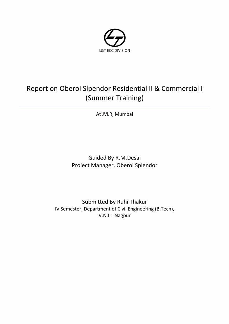
L&T Climbing System is used for tall structures like cooling towers, tankages, core walls, where staging or scaffolding along the interior or exterior walls would prove uneconomical. In the Climbing System, brackets are hooked to lost anchors, which are already provided along the cast wall. Entire shuttering is supported on the climbing brackets. The brackets are suitably braced to prevent any sway and are provided with walkways, working platforms and handrail for safety and ease of operation.
Varying degrees of sophistication are available in the climbing systems, a few of which are listed below:
CB - 150 A: Simple climbing, crane handled - platform width 1.50 m. The brackets and wall formwork are to be handled separately. Provision for extension of bracket width is also possible. CB - 150 F: Travel climbing, crane handled - platform width 1.50 m. Roll back arrangement for de-shuttering and cleaning of shutters. The wall formwork and climbing bracket are lifted as one unit. Provision for extension of bracket width is also possible. MF - 240: Travel climbing, crane handled - platform width 2.40 m. These brackets can also be fitted with automatic climbers like SKE-50 which is a hydraulic system (5 MT capacity). Automatic Climbing Formwork: The wall formwork along with the climbing brackets slide along the wall using hydraulics, thus eliminating the need for a crane. This system is very often used for core walls in high rise structures, cable stayed bridge pylons, natural draught cooling towers, etc.,
Figure 11: Structure of climbing formwork
Figure 10: Climbing Formwork

P a g e 23 | 39
They form structures of any shape and height independently of the crane - with Doka automatic climbing formwork SKE SKE is used for raising
large-area formwork elements
jointly with the climbing scaffold
in one single step
Without any craneage by one casting section at a time. SAFETY TYPE TESTED ACCORDING TO 89/392/EEC PRODUCTION SURVEILLANCE Doka automatic climbers are tested by independent institutes, who also certify their high quality and safety. Maximum safety in all phases of the work:
The climbing scaffold remains anchored to the concrete at all times.
The lifting mechanism is safely coupled to the climbing profile in every situation.
Wide working platforms, enclosed by handrails on all sides, enhance both safety and speed.
Hydromechanical drive provides optimum control and working safety:
Simultaneous controlling of: - up to 30 automatic climbers - by remote control - from anywhere on the platform
Isolating valves on the hydraulic cylinders (in case of hose rupture).
Open ring main.
Closed ring main.
Hydraulic units equipped with all necessary control features. High load-bearing capacity: Doka offers 2 types of automatic climber:
SKE 50, with 5 tonnes’ lifting capacity per automatic climber (this type is used), and
SKE 100, with 10 tonnes’ lifting capacity per automatic climber
(This enables the formwork to be optimally dimensioned to suit each project, which in turn greatly enhances the economic efficiency.) Makes work independent of climatic influences:
Permits safe working at wind speeds of up to 70 km/h
Climbing can take place irrespective of climatic influences.
Working platforms can be equipped with weatherproofing canopies. The advantages of “section-at-a-time” climbing:
Freely selectable operating sequence with no need for “round-the-clock” working.
The cycles are optimised for the construction task in question, right from the planning stage.
Rapid work rhythm: Form, strike, climb with no need for a crane irrespective of the weather condition independent of other forming operations, e.g. for trailing floor-slabs and walls lifting rate: 5 minim
Optimum adaptability to every layout: The Doka automatic climber SKE is a single-unit lifting appliance. This results in:
Figure 12: Climbing formwork

P a g e 24 | 39
Optimum configurations, irrespective of the shape of the layout.
Optimum configurations, irrespective of the shape of the layout.
Flexibility with regard to element widths.
Most economical solution can be achieved for all layouts of buildings, piers or shafts. Superlative product quality:
Sturdy, hot-dip galvanised components
Certified to ISO 9002 Salient Features
Eliminates the need for scaffolding to support the Wall Formwork
A three-level working platform for ease of working
Convenient working space and elbow room available in the climbing systems
Varying degrees of sophistication available depending on site requirements
Minimum skill and operation is required for anchoring and shuttering at each level
Fool proof arrangement for anchoring and safety lock system
P a g e 25 | 39
CONCRETE
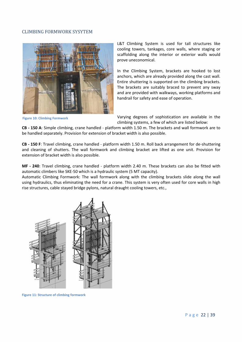
The concrete used in the project is READY MIXED CONCRETE. RMC as it is popularly called, refers to concrete that is specifically manufactured for delivery to the customer's construction site in a freshly mixed and plastic or unhardened state. Concrete itself is a mixture of Portland cement, water and aggregates comprising sand and gravel or crushed stone. Ready Mixed Concrete is manufactured under computer-controlled operations and transported and placed at site using sophisticated equipment and methods. RMC assures its customers numerous benefits. The concrete prepared at site is of grades varying from M10 to 80.
Advantages of Ready mix Concrete over Site mix Concrete A centralised concrete batching plant can serve a wide area. The plants are located in areas zoned for industrial use, and yet the delivery trucks can service residential
Districts or inner cities. Better quality concrete is produced. Elimination of storage space for basic materials at site. Elimination of procurement / hiring of plant and machinery Wastage of basic materials is avoided. Labour associated with production of concrete is eliminated. Time required is greatly reduced. Reduce cost
Figure 13: Concrete being poured in the column formwork and the Reinforcement
Figure 14: Concrete being poured in the column formwork and the Reinforcement

P a g e 26 | 39
ADMIXTURES
Type of concrete Admixtures
M10-M30 Retarders(Retardplast) M40-M50 Retarders + Plasticizers M60 & above Mineral Admixtures like Microsilica
Super plasticizers are also used along with microsilica. It cause low water cementation. It is either Naphtha based (for grade <M60) or Polycarboxylic based (PC for grade>M60).
STEEL
Steel used for construction purposes can be classified into mild steel and tor steel. STEEL
Mild Steel Tor Steel Soft Steel Normal Steel TMT
The steel used at the OBEROI SPENDOR SITE is Thermo mechanically treated (TMT) steel. Grade: Fe 500 Steel source: Vizag steel (Vishakapatnam); Mittal Arcellor and is supplied by the client for the current
site. It is then processed in the BAR BENDINING YARD.
BAR BENDING YARD
It is a yard off the site consisting of bar bending and cutting machine where majority of the reinforcement is cut. For the running of the bar bending yard a bar bending schedule or bar scheme diagram is prepared which is the comprehensive representation of cut and bend bars as per the design requirements of reinforcement detailer. It helps in determining appropriate material quantities, strength and cost estimation. The bars are bent into different shapes mainly rectangular or trapezoidal depending on the design criteria. Eg: Few dimensions of bent bars at the BAR BENDING YARD are as follows:-
100X100mm, 695X150mm, 270X150mm
Figure 15: Bar Bending Yard

P a g e 27 | 39
REINFORCEMENTS
CEMENT AND ITS ADMIXTURES
The cement used in tower Grande is ultra tech cement.
Its cost is Rupees 15 per kg.
1 bag can be used for a blockwork of 70 blocks.
Cement SBR Bonding Admixtures
SBR Bonding (styrene butadiene copolymer latex)
It is modified to be compatible with cement based mixes
Enhances mechanical properties such as adhesion, flexibility, compression and impact strength of concrete.
Improves thin section fragility of cement when coating.
It is suitable in damp conditions
Improves water resistance to the mix
Improves workability
Allows thinner section and reduction in water content
Reduces cracking
Improves chemical and abrasion resistance
Typical Application
1) Bonding agent for application of cement
Imparts high bonding properties for sticking gypsum on bricks & concrete surface.
Mixing ratio Dilute 1litre of water and apply on the surface.
Figure 16: Top Vied of Reinforcement on podium 2

P a g e 28 | 39
Mix 1.5 litre SBR in 200 Litre of water and water has to be used in gypsum to make mix for application.
GYPSUM Gyproc gypsum was used in Tower Grande
Each bag of gypro consist of 25kg of gypsum M.R.P. Rs 270/- per bag 1 Flat(3 BHK) requires 225 bags of Gyproc It has 10-15 mins initial settling time And has a final settling time of 20mins 1 bag covers an area of 15m2-2m2 area approx.
BLOCKWORK
The concrete blocks used for bockwork in the Tower Grande are AEROCON blocks. It is an ideal substitute for traditional clay bricks and hollow concrete blocks used for wall construction. The basic raw materials used in production of Aerocon blocks are Cement, Fly ash, lime and water. These blocks are in range from a thickness of 75mm to 200mm respectively. They can also be made to required size. Aerocon can be plastered, painted, and dry lined or tiled. Aerocon's micro cellular structure incorporates millions of pockets of trapped air which gives it characteristic light weight, high thermal insulation and excellent frost and water resistance. It is used for all kinds of interior and external walls. ADVANTAGES
Aerocon is extremely light, just one-third the weight of clay bricks and are much easier to handle on the site.
Aerial covers the same are as that 14 clay bricks do, enabling a faster construction results in saving of labour, time and material.
Aerocon's excellent thermal properties,helps in saving recurring costs of heating and cooling. It is fire resistant. It is moisture resistant.
COST FACTOR SIZES COSTS 600 X 200 X 200 76.99 600 X 200 X 150 57.59 600 X 200 X 100 38.40
Figure 17: Blockwork

P a g e 29 | 39
METHOD OF CONSTRUCTIONS MIVAN FORMWORK
WORK PROCEDURE
1. Transferring of survey points. 2. Setting out lines for all walls and columns
in X and Y direction with addition of offset line in 300mm.
3. Corrective measures if any shall be taking for adjustment of rebar.
4. Concrete slab level survey (checking levels) near wall and column lines and Kicker (starter) level survey.
5. Adjust level if any required (Allowable
level difference +/- 8mm) 6. Fixing of timber stay in walls and column
lines at minimum 1 m c/c to restrict the formwork movement laterally. 7. Cleaning of form face and side rails using scrubber and applying form release agent on form face and
side rails. 8. Ensure that all vertical formwork is erected as per setting out line. 9. External walls panels shall be erected on kickers and ensure checking of plumb in internal walls. 10. Erection of deck formwork for slab and ensure that all PL are in plumb. 11. Check that all required wall ties, pins, wedges and kicker bolts are fixed in place. 12. If wall ties are missing due to falling of reinforcement, steel waler shall be provided as extra supports
at such places. 13. Check that all kickers, rockers are fixed in place and aligned. 14. During concreting check that finished slab level is maintained 50 mm below kicker top using level instrument. 15. Ensure that sunken form work is removed only after 12 hrs, to facilitate easy stripping. 16. Vertical forms of walls and columns shall be removed after 16 hrs. 17. Deck form work in slab shall be removed only after 72 hrs. 18. PL shall be removed only after 7 days for slab and beams respectively.
Finishing of Mivan sleeve holes and through tie rod holes in concrete surfaces and also for treating deep
pockets on the concrete surfaces
MATERIALS: Cebex-100 or equivalent material, Cement, Sand and Water. Site tested Ordinary Portland cement conforming to IS: 12269 or Portland Pozzolana cement confirming to IS: 1489 shall be used. Sand fraction passing 1.18 mm IS sieve and retained over 150 micron IS sieve and kept in dry condition shall be used for the mix.Water to be used shall be of Potable Quality standard.
Figure 18: Mivan Assembly
Figure 19: Setup of formwork

P a g e 30 | 39
MIX PROPORTION: Cement based Dry Pack Mix shall be proportioned by weight. Mix one packet of Cebex-100 (250 g) weight with 50 Kg of Cement, dry mixed with two and half parts by weight of sand. Sufficient amount of water shall be added to the dry mix and subsequently vigorously blended to produce a cement mortar of such a consistency that shall stick together when moulded into a ball by slight hand pressure. The paste, thus formed, shall not extrude any water but shall leave the hands just damp. SURFACE PREPARATION: Remove the sleeve / tie rod and PVC lining from hole. Unsound portion of the concrete surface shall be chipped off and cleaned thoroughly to remove all loose mortar and foreign materials by application of pressurized air jet or wire brush. WORK PROCEDURE 1. Surface of the pockets shall be wetted for before start of grouting work. The holes shall be slightly wet with no free water on the surface. 2. The surface shall then be dusted lightly with cement by means of dry brush. Under no conditions shall the pocket be painted with neat cement grout. 3. Cement and sand in specified proportion shall taken. Mix one packet of Cebex-100 (250 g) weight with 50 Kg of Cement, dry mixed with two and half parts by weight of sand. 4. Enough water shall then be added to the dry mix and blended vigorously. Mix shall be placed and packed in layers having a compacted thickness of about 20 mm. Each layer shall be solidly compacted over its entire surface by use of hard wood stick and hammer. The stick is normally about 300 mm to 450 mm long and not over 30 mm in diameter. 5. Most of the tamping shall be directed at a slight angle towards the side of the pocket to ensure maximum compaction and bond. Extra water shall not be used to facilitate finishing. 6. Curing: Immediately after patching, the patched area shall be covered with a non-staining, water saturated material. The covering sheet shall be kept wet and protected against sun and wind for a period of 12 Hrs. Thereafter the patched area shall be kept continuously moist for at least three days for achievement of specified strength.
OTHER ASPECTS: Repairs shall be started as early as practicable after removal of formwork and in a manner to meet the requirements of the finish specified for the particular location. The portion of concrete to be repaired shall be inspected by the Engineer- in-charge before commencement of work.
BLOCKWORK
WORK PROCEDURE:
1. Layout all internal walls in entire wing at floor level. 2. Set one course of block work according to the
layout. Proper clear opening for setting door frame & backing is provided.
3. This layout is to be checked by site engineers to have minimum required thickness of plastering on long walls & square alignment for tiling works.
4. Block work construction in Greecobond mortar. 5. All door joints & wall joints shall be properly filled
and flushed with mortar so that no hollow spaces are left.
Figure 20: Laying of Blockwork

P a g e 31 | 39
6. Plumb & alignments of block work is checked & maintained. Outside plumb to be maintained for external faces.
7. Provision for further extension shall be made by toothing at the end of the wall. 8. The Block work shall be raised upto about 1M in one day preferably at bottom lvl. Of Patli 9. Horizontal stiffeners 4” shall be provided at mid height along full length with patli hook. Scrap Steel
bars to be used in patli with ‘U’ bar for tie. 11. Broken blocks should not be used except for Closure. The closures shall be strictly plumb, joints shall be broken rustically. 12. CC wedges to be used at all blocks between beams/column joints. 13. Date is to be put
WATER PROOFING
WORK PROCEDURE: 1) Surface where water proofing is to done shall be thoroughly cleaned with wire brush and made free
from dust, grease and loose material. 2) Defects in concrete surface if any shall be rectified and tie holes shall be plugged. 3) Groove cutting up to 15 mm depth shall be done in joints of horizontal and vertical RCC members
using chisel and hammer. 4) Ponding the area for 24 hrs to check for leakages. If leakages observed, then do pressure grouting
with cement slurry.
5) Applying Rheomax 707 over groove area and filling the joint with cement mortar (1:3) to cover the whole groove portion.
6) Ponding test shoud be done for 24 hrs to check for leakages. 7) Application of base coat on floor and wall portion covering up to height of 1.2 m above sunk.
(Rheomax 707 is used with 1:3 CM @ 160 ml / bag of cement). 8) Ponding test for 3 days (If ponding test fails remove and re-do the entire base coat). 9) Construction of ledge wall where required and curing for 3 days. 10) There after complete plumbing works for ledge wall in toilet portion and after testing encase the
plumbing lines. 11) Brick bat coba with cement mortar (1:3) and required slope towards drain traps pipes. 12) Carrying out IPS according to slope with (1:4) CM and Rheomix 141 @160 ml / bag of cement. 13) Curing for next 7 days by ponding.
GYPSUM PLASTERING WORK PROCEDURE:
1. Ensure that entire RCC surface to be plastered is hacked with chisel and hammer. (1” c/c) 2. Start plaster from ceiling and work down towards floor. 3. RCC surface shall be cleaned thoroughly to remove dirt and grease if any. 4. Apply bonding coat to RCC surface (Flexi bond: Cement: Water) in ratio of (1:4:1) by weight.
P a g e 32 | 39
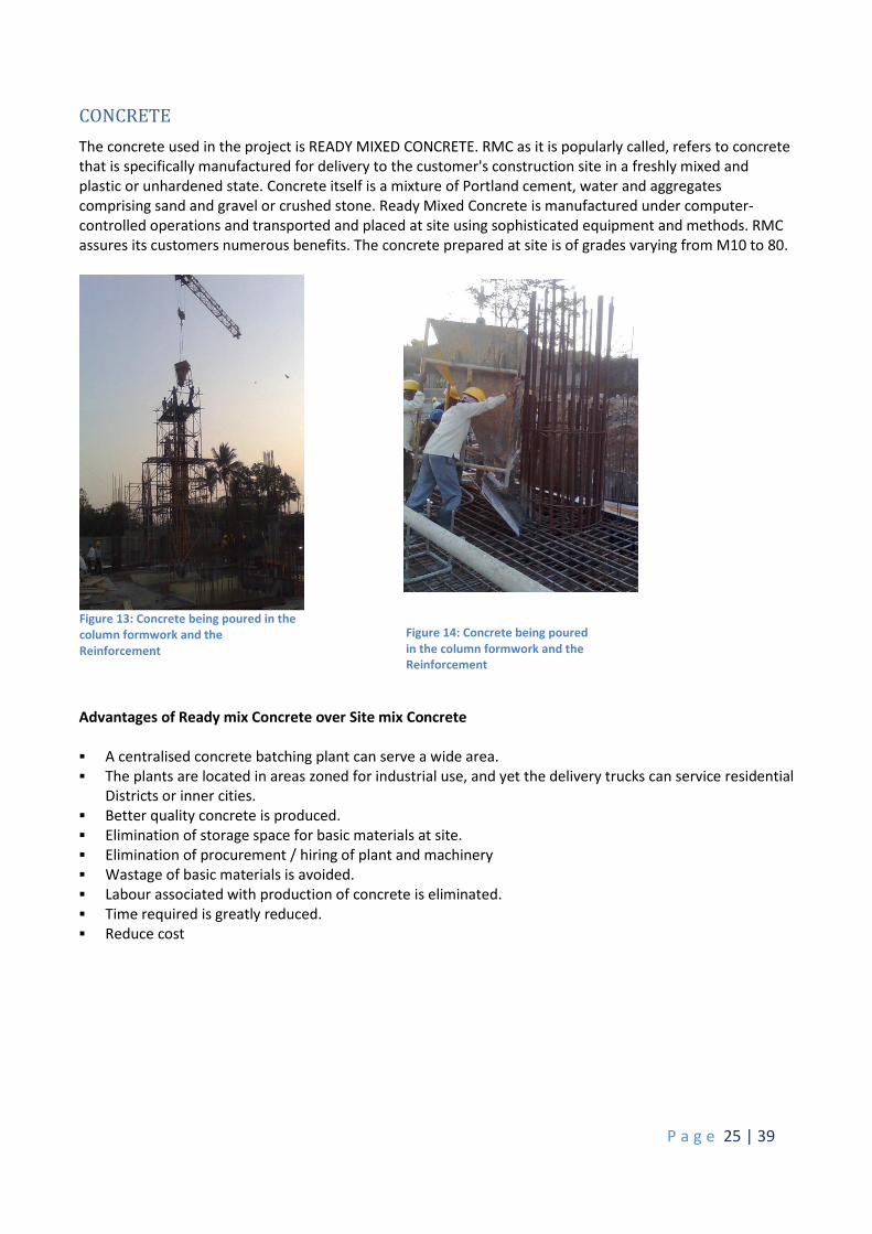
5. Chat coat to be applied where ever required. 6. Fixing flexible mesh at junctions of block masonry and RCC also on electric chasing repair using u-
nails. 7. Add dry Gypsum powder in water in ratio of (4:3) and mix thoroughly to prepare thick paste. 8. Provide level pads (thiyyas) at various levels and corners. 9. Provide tikki dhada 3’- 0” c/c with plumb & 10. Spread gypsum paste in layers, and level using straight edge and plumb bob. 11. Average thickness of plaster shall be kept 10 mm. 12. Lightly scour the surface with damp sponge and protect for next 3 hrs.
EXTERNAL PLASTERING
WORK PROCEDURE: 1. Surface where plastering is to done shall be thoroughly cleaned with wire brush and made free from
slurry droppings, dust, grease and loose material and tie holes shall be plugged. 2. All RCC members should be hacked using hacking tool 50 to 70 mm C/C. 3. Fix in position level pads at spacing of not more than one length of straight edge for entire surface to
be plastered and keep 150 mm from corners. 4. Check level pads for thickness, if thk is more do carry out make up coat, and scratch surface rough to
receive plaster. If thk. is less carry out chipping, so that minimum thk of plaster is as specified. 5. Left out joints and gaps between block work and RCC member should be filled with 10 mm
aggregates and mortar. 6. Fix in position chicken mesh 200 mm width in joints, equally spaced on block work and RCC. 7. Wet the surface one hour before starting of plaster. 8. Plastering shall commence from top and worked downwards to floor. 9. Coreplast LW liquid water proofing admixture should be added to mixing water 100 ml. per bag of
cement for first 12 mm coat. 10. Mortar shall be in proportion (1:4) CM, mix dry sand and cement thoroughly before adding water,
use tray for mixing.Add water to portion of dry mix only to be consumed within next 2 hrs. 11. Throw the mortar for area coverable by straight edge, both vertically and horizontally in
one stretch. 12. Do level the surface using straight edge.
Figure 22: RCC being chiselled Figure 21: Mesh fixed at junctions

P a g e 33 | 39
13. Float the surface and finish as per required thickness for entire area in stages and check for plumb and level.
14. Provide first coat of 12 mm thk. With cement mortar (1:4) and water proofing admixture. Make surface rough to receive second coat and Curing shall be done for 3 days.
15. Provide second coat of 8 mm thk. With cement mortar (1:4).Ensure that stages, in plastering work are not apparently visible.
16. Curing to be done for 7 days.
DOOR FIXING
WORK PROCEDURE:
1. Ensure that entire wall opening is to the required sizes & locations of frame fixing anchors in block work are left open.
2. Door frame is set in the opening & braced to maintain plumb & level. 3. Ensure square of the all edges are correct. 4. Anchor locations are then cast in concrete with formwork. 5. Block work completed up to lintel level. 6. Precast lintel is installed on the block work with soffit at frame top level.
Figure 24: Door Frame being fixed Figure 23: Door attached to the frame

P a g e 34 | 39
BATCHING PLANT Components of Batching Plant at OBEROI SPLENDOR
1. Hopper
2. Conveyor belts
3. Feeder
4. Pan mixer
5. Silos
6. Transit mixer
7. Weigh batcher
8. Control system
9. Quality control lab
The capacity of the Batching Plant
Theoretical capacity: 30m3/hr
Average Capacity: 22m3/hr
It produces concrete of grades M10 to M80
Calibration of the Batching Plant (RMC plant) is done once a month.
Permissible values of cement and aggregates are 2% and 3% respectively according to the IS code IS4926 RMC.
Fig b Figure 28: Conveyor Belt
Figure 26: Batching Plant Controls
Figure 27: Concrete Cubes for testing
Figure 25: Schematic presentation of Concrete Production

P a g e 35 | 39
Key Points
1) For temperatures of concrete more than 70°C chilled water or crushes ice should be used while mixing concrete.
2) To avoid cement particle wastage during transfer from bulker to the Silos, Filters are provided near the silos. These filters are cleaned weekly.
3) The sprinklers provided, saturate the aggregates o that no water is absorbed from the concrete. If this is not done then specific adjustments in the required water quantity is made.
4) There are additional vibrators attached to the feed hopper to remove the aggregates which are stuck to the surface of the hopper during monsoons.
Various tests carried out on individual materials
1) Testing of Cement a) Initial Settling Time b) Final Settling Time c) Standard Consistency test d) Field test
Greenish grey colour
When hand placed in cement should give a cool smooth finish
No lump formation should be observed 2) Testing of aggregates
a) Mechanical sieve shaker b) Water absorption and Specific Gravity is checked once a month provided the source remains
same. c) Moisture content test are carried out n daily basis hence water content is adjusted d) QCL
Gradation of aggregates
Moisture content
Crushing value
Flakiness & elongation 3) Testing of admixtures
a) Marsh cone test b) Shrinkage test
4) Testing of concrete a) CTM(Compressive Testing Machine) b) Slump Test

P a g e 36 | 39
CONSTRUCTIONAL PROBLEMS AND DISCOVERIES SHORTCOMINGS of the project:
In the tower Grande 1st floor slab of wing 2 and the shear wall at Podium level 2 developed cracks. This was the result of malfunctioning of the batching plant. The concrete provided by the plant had a much higher percentage of fly-ash compared to cement. Therefore the grade of concrete produced was in inappropriate for the above mentioned construction.
There were NDT (non-destructive tests) were carried out for the above 2 sections. The tests included 10. Rebound hammer test to check the harness of the concrete in the shear wall and the slab 11. Core Cutter Test in which a core (depth being twice of diameter) of the slab was obtained. This core
was checked for compressive strength test and composition and content test in which the sample core happened to fail.
One of the major problem faced at site was labour shortage due to which there will be a delay in the completion time of the project.

P a g e 37 | 39
QUALITY MANAGEMENT SYSTEM L&T-ECC at this site has a well-established and documented Quality Management System (QMS) as per the requirements of ISO 9001:2008. Relevant procedures have been established which clearly specify the criteria and method for effective operation, control and necessary resources and information to support the operation and monitoring of these processes. There are procedures for monitoring, measuring and analysing the processes so that necessary action can be taken to achieve the desired results, and continuously improve these processes. The Project Quality Plan comprises of three sections: 1. Volume-1
ISO Manual 2. Volume-2
Work Procedures Inspection Test Plan Project Quality Check
3. Volume-3 Formats
Volume1 ISO Manual It is the quality manual of ECC division. It constitutes sections, which give information about management responsibility, resource management, and quality management system. Volume2 Work Procedures Work procedures for all civil, mechanical, electrical, structural activities are described in detail in the work procedure section. Inspection Test Plan Inspection Test Plan provides information related to testing and inspection to be conducted on various activities. There is a checklist of inspections to be done on various activities. The ITP for an activity comprises the activity name, nature of check/inspection, method of check, frequency of check, reference procedure/check, and format for record, inspection authority name, and remarks. Project Quality Check Sampling approach is used for measuring construction work against specification. The responsibility of Quality checks rests on auditor and the quality control engineer. The project quality check gives the sampling criteria, the area of check, and nature of check and maximum points that can be given to each sub-check.

P a g e 38 | 39
HEALTH, SAFETY AND ENIVIRONMENT SYSTEM Larsen and Toubro Limited- ECC Division, Buildings and Factories Operating Company - affirms its commitment to provide a safe and healthy workplace for all its employees and ensure that its operations are carried out in the manner that protects the environment and community in general. The objectives of the policy shall be achieved at workplace by:
Promoting a positive HSE culture;
Complying with all applicable HSE legislation;
Identifying/Eliminating/Preventing/Controlling Hazards and pollution that could cause accidents, illness or environmental harm;
Providing training and resources for employees to maintain HSE systems;
Integrating HSE procedures in to every operations in the company;
Employing contractors who aspire to adopt the same HSE standards in their work;
Continually improving the HSE management and HSE performance;

P a g e 39 | 39
BIBLIOGRAPHY Data observed from Larson and Toubro site at Jogeshwari east, Mumbai, India Larson and Toubro management guide. Larson and Toubro quality control guide