report pm83966 06 version 1 - anec report swing impact test en71-8.pdf · test report pm 83996/06...
TRANSCRIPT

TEST REPORT PM 83996/06 2006-09-22
ROUND ROBIN TEST REGARDING TEST-METHOD AND REQUIREMENTS FOR IMPACT FROM
SWING ELEMENTS IN EN 71-8
Commissioned by ANEC and the Swedish Consumer Agency
S M P S V E N S K M A S K I N P R O V N I N G A B
SMP Uppsala: Fyrisborgsgatan 3, 754 50 Uppsala Tel: 018-56 15 00 Fax: 018-12 72 44 SMP Malmö: Box 56, 230 53 Alnarp Tel: 040-46 44 20 Fax: 040-46 01 13 SMP Umeå: Box 4053, 904 03 Umeå Tel: 090-70 83 70 Fax: 090-13 65 62
E-post: [email protected] Internet: www.smp.nu
CO
PY

REPORT
Date Our reference
2006-09-22 PM 83996/06 Page 1 of 12
SMP SVENSK MASKINPROVNING AB (The Swedish Machinery Testing Institute) Email: [email protected]
UPPSALA (Head Office) Fyrisborgsgatan 3, SE-754 50 Uppsala, Sweden, Phone: +46 18 56 15 00, Fax: +46 18 12 72 44 VAT: SE5565296836
MALMÖ Box 56, SE-230 53 Alnarp, Sweden, Visiting address: Sundsvägen 8, Alnarp, Phone: +46 40 46 44 20, Fax: +46 40 46 01 13
UMEÅ Box 4053, SE-904 03 Umeå, Sweden, Visiting address: Verkstadsgatan 17 (SE-904 32), Phone: +46 90 70 83 70, Fax: +46 90 13 65 62 www.smp.nu
CO
PY
ROUND ROBIN TEST REGARDING TEST-METHOD AND REQUIREMENTS FOR IMPACT FROM SWING ELEMENTS IN EN 71-8 Background In EN 1176-2: 1999 “Playground equipment – Part 2: Additional specific safety requirements and test methods for swings”, requirements and test methods for “impact from swing elements” are given. Parts of these requirements were copied into EN 71-8 “Safety of Toys – Part 8: Swings, sides and similar activity toys for indoor and outdoor family domestic use” (harmonised under the Safety of Toys-directive). The method and requirements were questioned by many experts in CEN/TC 52/WG 3 “Safety of Toys – Mechanical and Physical Properties” arguing that the test method had not been verified for the new application in EN 71-8 and that it did not give reproducible results. Similar criticism had previously been made against EN 1176-2. In document TC136/SC1 N459 (from 011030) a reference is made to a round robin test carried out in 1998 which it is said that “There was found to be a wide variation in results between test houses, 34% in the worst case.”. In document TC136/SC1 N469 (from 011216), it is stated that “although the round robin tests in the early days had shown up big differences, it was much better now. It was agreed that a better defined reproducible test method should be developed during the revision of the standard.” However, during the recent revision of 1176-2, this issue has, to our knowledge, not been brought up by any expert or organisation. The criticism against the method and requirements in EN 71-8 resulted in the adoption of a resolution (majority decision) in CEN/TC 52 to delete the swing impact test and corresponding requirements from EN 71-8. The amendment to EN 71-8 was published by CEN in December 2005 but has not yet (September 2006) been referenced in the OJEU since a formal objections has been launched against it. The resolution to delete the method also stated that a small task group was to be established with the task to study the requirements and test methods, including a comparison with EN 1176, and to validate the test methods and thereafter, if appropriate, propose WG 3 to include a revised method this in EN 71-8. For this reason, a small Nordic Project was carried out with the aim to apply the present test method at two laboratories, one in Denmark and one in Sweden, and to identify any unclear parts of the standard text and thereafter, if possible, propose improvements to the method. SMP carried out the project in which some 50 tests were carried out to gain an overall impression of the repeatability of the method and to identify factors that have an affect on the test results.
Date Our reference
2006-09-22 PM 83996/06 Page 2 of 12
CO
PY
The outcome of the Nordic project (see Appendix 3) was a revised text for the test method and requirements, which could be used as a basis for a round-robin test, involving several test laboratories from different European countries. Prior to a proposal for re-introducing requirements and test methods for swing impact in EN 71-8, it is necessary to validate the test method as suggested by the Nordic project. SMP therefore obtained financing for a round robin-test from ANEC and from the Swedish Konsumentverket in Sweden. Purpose and scope of the project The purpose of the project was to carry out a round-robin test, involving test laboratories from different European countries, in order to validate the revised proposal for the requirements and test methods for impact from swing elements, which in its turn can provide a basis to propose a re-introduction in EN 71-8. The scope of the round robin test was to focus on validation of the proposal for revised method and requirements for impact from swing elements (resulting from the Nordic project which was carried out in 2005 by SMP). Participants At a meeting of CEN/TC52/WG (26-28 October 2005) three testing laboratories expressed their interest in participating in the round robin test and later a fourth laboratory was added to the list of participating laboratories:
1. SMP Svensk Maskinprovning AB – Sweden 2. Consumer Agency/Customs Laboratory (Tullilaboratorio) - Finland 3. IISG - Istituto Italiano Sicurezza dei Giocattoli – Italy 4. Bureau Veritas CPS – France
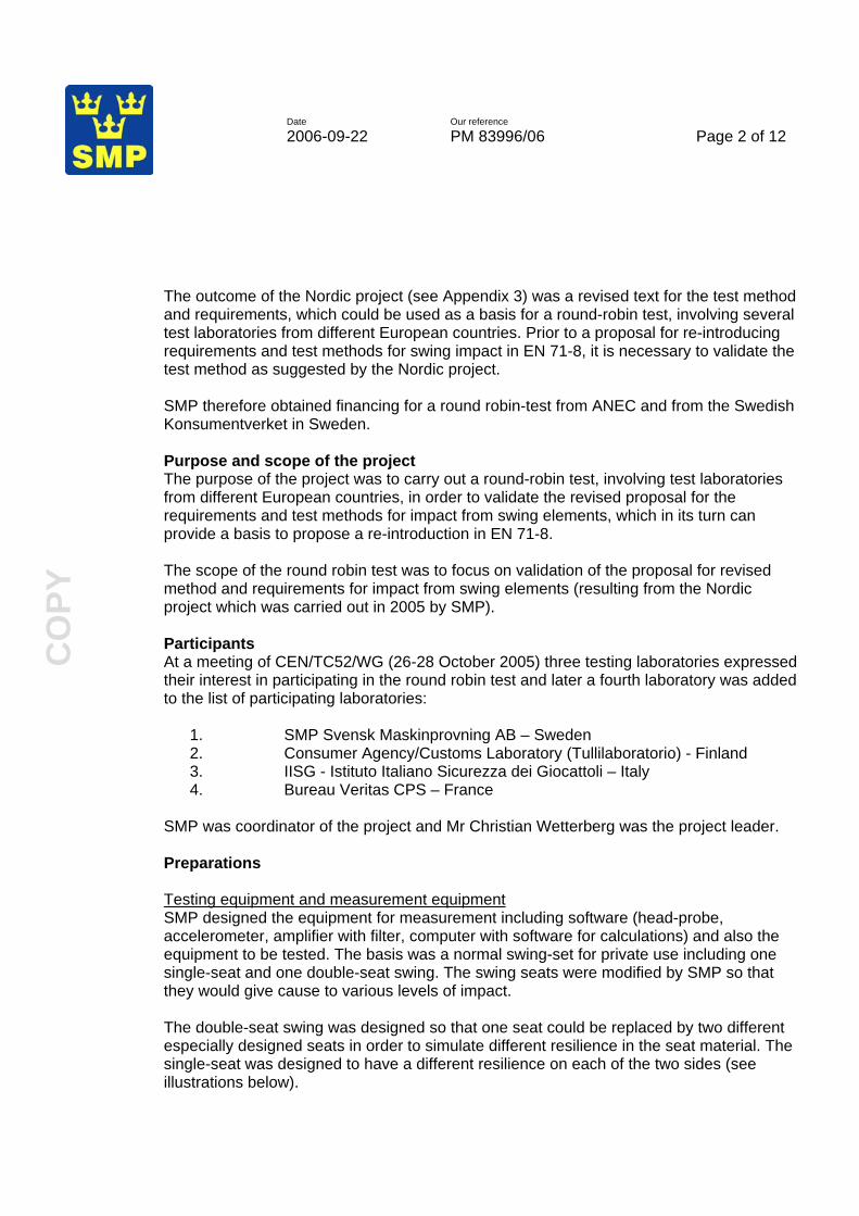
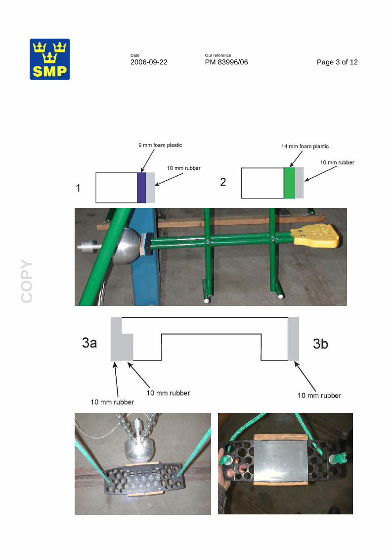
SMP was coordinator of the project and Mr Christian Wetterberg was the project leader. Preparations Testing equipment and measurement equipment SMP designed the equipment for measurement including software (head-probe, accelerometer, amplifier with filter, computer with software for calculations) and also the equipment to be tested. The basis was a normal swing-set for private use including one single-seat and one double-seat swing. The swing seats were modified by SMP so that they would give cause to various levels of impact. The double-seat swing was designed so that one seat could be replaced by two different especially designed seats in order to simulate different resilience in the seat material. The single-seat was designed to have a different resilience on each of the two sides (see illustrations below).
Date Our reference
2006-09-22 PM 83996/06 Page 3 of 12
CO
PY

Date Our reference
2006-09-22 PM 83996/06 Page 4 of 12
CO
PY
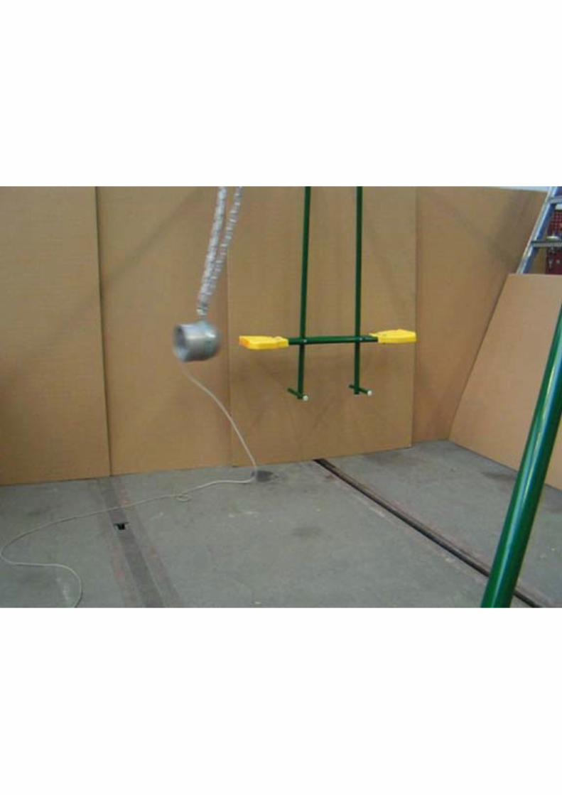
All testing equipment, including the frame for the swings, and measuring equipment was sent to each participating laboratory prior to the tests, together with assembly instructions (see Appendix 1). The weight of the double swing was 3,75 kg including suspending rods and the free-hanging swing weighed 1,32 kg with ropes and 1,15 kg without. The rope-length from the suspension point to the centre of the seat was 1 430 mm. Test equipment and procedure Test equipment The dimensions of the test-mass are shown in the figure below. A tri-axial accelerometer (range ± 500 g, 10 kHz butterworth-filter, sampling frequency 10 kHz) was mounted in the centre of the test-mass and connected to the amplifier and computer. See Appendix 4 for specification of accelerometer Endevco 7264B-500 and Appendix 5 for specification of amplifier Endevco Model 136.

Date Our reference
2006-09-22 PM 83996/06 Page 5 of 12
CO
PY
An example of a typical impact curve (in the z-direction) is shown in the figure below.
Z acceleration [G]
-10
0
10
20
30
40
50
60
70
80
90
1 17 33 49 65 81 97 113 129 145 161 177 193 209 225 241 257 273 289 305 321 337 353 369 385 401 417 433 449 465 481 497 513 529 545
The g-force was calculated as the RMS (Root Mean Square) of the g-force in the three measured directions. Test procedure for swing and test-mass set-up and release • The swing was adjusted according to the instructions • The swing was suspended with the means of suspension that was supplied with the
swing and at the maximum height that these permitted • The test mass was suspended and adjusted so that the contact points of the swing
element and the centre of the test mass were in the same horizontal plane as the centre of gravity of the test mass
• The seat was raised along its arc of travel until the side view projection of a straight line through the pivot point and index mark, formed an angle of 60 degrees to the vertical.
• The seat was supported in the raised position by a mechanism that provided release without the application of external forces (which would disturb the trajectory of the suspended object)
• It was ensured that the seat and suspending elements were motionless and thereafter the seat was released so that the assembly travelled in a smooth downward arc without any visible oscillations or rotations of the seat (which would prevent it from striking the test mass at the impact point)
Prior to the start of each series of measurement, it shall be secured that the intended point of impact is achieved: Mark the centre of the test-mass, (+), with a suitable marker (chalk) so that an imprint is obtained on the impact surface of the seat.

Date Our reference
2006-09-22 PM 83996/06 Page 6 of 12
CO
PY
Check and, if necessary, make fine adjustments of the test mass in the vertical and horizontal directions. Repeat the procedure until repeatability has been obtained for the intended point of impact. Pilot study When all adjustments had been made and everything was set for the respective test series, measurements and documentation of each set-up was made in accordance with the SMP-instructions. For each impact and test-series, the registered peak acceleration was copied from the computer sceen to the test-result sheet (supplied by SMP). Each impact result was also saved in the computer (carried out by SMP). All deviances such as ”impure” or ”slanted” impacts or any other indications that the impact has not been correctly carried out was noted in the test-result sheet. In order to avoid that the marking used for measurement of impact-surface (series II, seat 2) would influence the result, chalk was used as marker. Test procedure for measurement of surface compression The exposed impact area (the area of the seat that has made contact with the test mass) was be measured by applying chalk to the test mass and by measuring the coloured (chalked) surface on the swing element after the impact. A transparent celluloid-film (such as that used for OH-projectors) was used in order to make a copy of the impact-area. Thereafter, a “millimetre-paper” was placed under the film and the exact area calculated. Testing programme SMP developed a testing programme that was circulated to the participating laboratories, together with detailed instructions for the test procedure (see Appendix 2). The programme consisted of the following tests: I. Seat 1 (double-swing): 20 impacts with the aim to have the point of impact in the centre. II: Seat 2 (double-swing): 10 impacts with the aim to have the point of impact in the centre. Determination of impact surface after every single impact. III. Seat 3 b) (free-hanging swing): 25 impacts with the aim to have the point of impact in the centre. Measurement of the vertical point of impact after every single impact. IV. Seat 3 a) (free-hanging swing): Three series of 7 impacts each where the aim is to have the point if impact in the centre in the first series, 10 mm above the centre in the second series and 10 mm below the centre in the third series. Measurement of the vertical point of impact after every single impact.

Date Our reference
2006-09-22 PM 83996/06 Page 7 of 12
CO
PY
Results Tests with seat 1 (double swing with 9 mm plastic foam and 10 mm rubber) The results from the 20 impacts (each country) showed that the average g-force varied as follows:
Swed
en
Finl
and
Italy
Fran
ce
Swed
en II
Average 20 impacts 57,4 54,69 56,37 58,48 55,70Min: 56,3 53,5 54,3 56,6 53,1 Max. 59,3 55,8 59,4 61,7 59,0 Deviation Min-Max: 5,3% 4,3% 9,4% 9,0% 11,1% Excluding Min-Max of the 20 impacts: Min: 57,1 54,2 54,4 57,2 54 Max. 57,8 55,3 58,3 59,9 57,6 Deviation Min-Max: 1,2% 2,0% 7,2% 4,7% 6,7%
Note. Sweden l, only includes 10 impacts. The others include 20 impacts. Deleting the two extreme values in every set of tests to see how the deviation min-max changes, gives an idea of whether any “outlyers” have had great effect on the deviation. The results from the tests with the double swing with a thin (9 mm) plastic-foam layer show the following variations: Min-Max variation in tests made within one country: All values included: Always less than approx. 11 % (see table above) Two extreme values deleted: Always less than approx. 7 % (see table above) Min-Max variation in all tests regardless of country (total 90 tests) All values included: Approx 16 % (see appendix 7) Two extreme values deleted: Approx 11 % (see appendix 7)

Date Our reference
2006-09-22 PM 83996/06 Page 8 of 12
CO
PY
Tests with seat 2 (double swing with 14 mm plastic foam and 10 mm rubber) The results from the 10 impacts (each country) showed that the average g-force varied as follows:
SWEDEN FINLAND ITALY FRANCE SWEDEN
ll
Average 10 impacts
Measured value
g
Area
cm2
Surface
compression
N/cm
2
Measured value
g
Area
cm2
Surface
compression
N/cm
2
Measured value
g
Area
cm2
Surface
compression
N/cm
2
Measured value
g
Area
cm2
Surface
compression
N/cm
2
Measured value
g
Min: 48,1 27,4 76,0 45,7 26,5 75,4 45,5 27,0 75,9 45,6 24,8 83,3 44,4 Max. 50,3 28,7 83,2 47,9 27,6 80,2 52,7 28,0 87,5 51,0 26,8 89,9 50,2 Deviation Min-Max: 4,6% 4,7% 9,5% 4,8% 4,2% 6,4% 15,8% 3,7% 15,3% 11,8% 8,1% 7,9% 13,1%
Excluding Min-Max of the 10 impacts: Min: 49,0 27,5 76,8 45,9 26,8 77,7 46,2 27,2 76,1 49,7 25,3 85,5 45,2 Max. 50,0 28,6 82,6 47,4 27,6 79,6 50,7 27,9 85,1 50,9 26,5 89 48,2 Deviation Min-Max: 2,0% 4,0% 7,6% 3,3% 3,0% 2,4% 9,7% 2,6% 11,8% 2,4% 4,7% 4,1% 6,6%
g-force results (columns with white background) The results from the tests with the double swing with a thicker (14 mm) plastic-foam layer show the following min-max variation for the g-force: Min-Max variation in tests made within one country All values included: Always less than approx. 16 % (see table above) Two extreme values deleted: Always less than approx. 10 % (see table above) Min-Max variation in all tests regardless of country (total 50 tests) All values included: Approx 19 % (see appendix 7) Two extreme values deleted: Approx 13 % (see appendix 7) It can be concluded that the variation in the results is on approximately the same the same for the two different impact surfaces of the double swing and that the variation in the results was significantly reduced when outlying values were deleted. Note that all values (regardless of whether the impact was “clean” or not) have been included in the calculations. It can also be noted that g-forces from a double swing with a resilient material as impact surface can be below 50 g.

Date Our reference
2006-09-22 PM 83996/06 Page 9 of 12
CO
PY
Impact-area results (columns with green background) When analyzing the data from the impact-area results, there has been some uncertainty regarding the values from France since they were calculated based on the weight of the area of transparent paper that corresponded to the impact area. Since it is difficult to assess the effect of this method for alternative method for measurement (however, the obtained values are lower than for the tests in the other countries), calculations for the variation have been made both including and excluding the French values. Min-Max variation in tests made within one country (including French values) All values included: Always less than approx. 8 % (see table above) Two extreme values deleted: Always less than approx. 5 % (see table above) Min-Max variation in all tests regardless of country (total 40 tests –France included) All values included: Approx 16 % (see appendix 7) Two extreme values deleted: Approx 13 % (see appendix 7) Min-Max variation in all tests regardless of country (total 30 tests – France excluded) All values included: Approx 8 % (see appendix 7) Two extreme values deleted: Approx 7 % (see appendix 7) Surface compression (columns with grey background) The surface compression (force per impact-area) is calculated by multiplying the mass of the test-mass (4,62 kg) with the g-force and the acceleration due to gravity 9,81 and by dividing this by the measured impact-area. Therefore, the variation in the results depends on the variation in the g-force and impact-area measurements. Again, the calculations regarding variation have been made both including and excluding the results from France. Min-Max variation in tests made within one country (including French values) All values included: Always less than approx. 15 % (see table above) Two extreme values deleted: Always less than approx. 12 % (see table above) Min-Max variation in all tests regardless of country (total 40 tests –France included) All values included: Approx 20 % (see appendix 7) Two extreme values deleted: Approx 17 % (see appendix 7) Min-Max variation in all tests regardless of country (total 30 tests – France excluded) All values included: Approx 16 % (see appendix 7) Two extreme values deleted: Approx 12 % (see appendix 7) Tests with seat 3 b (free-hanging swing with homogenous impact surface) In these tests, 25 impact-tests were performed in each country (total 125 tests) and any deviation from the horizontal line (up-down from the centre) was registered. In the diagram below, the results have been plotted to show the registered values in relation to the measured deviation in millimetres from the horizontal line.
Date Our reference
2006-09-22 PM 83996/06 Page 10 of 12
CO
PY
Test III Seat 3b
0
10
20
30
40
50
60
70
80
90
100
-8 -6 -4 -2 0 2 4
Vertical impact deviation: Above (+) and Below (-)
Mea
sure
d (g
) SWEFINITAFRASWE2
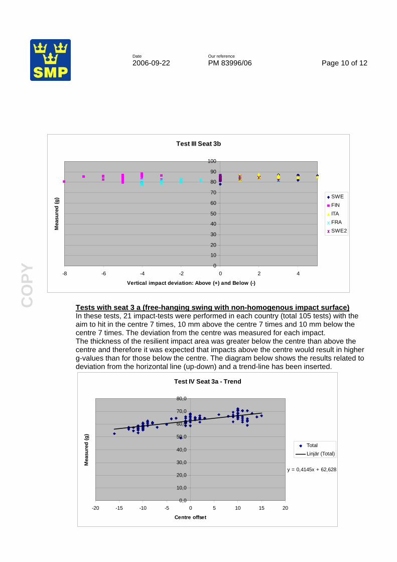
Tests with seat 3 a (free-hanging swing with non-homogenous impact surface) In these tests, 21 impact-tests were performed in each country (total 105 tests) with the aim to hit in the centre 7 times, 10 mm above the centre 7 times and 10 mm below the centre 7 times. The deviation from the centre was measured for each impact. The thickness of the resilient impact area was greater below the centre than above the centre and therefore it was expected that impacts above the centre would result in higher g-values than for those below the centre. The diagram below shows the results related to deviation from the horizontal line (up-down) and a trend-line has been inserted.
Test IV Seat 3a - Trend
y = 0,4145x + 62,628
0,0
10,0
20,0
30,0
40,0
50,0
60,0
70,0
80,0
-20 -15 -10 -5 0 5 10 15 20
Centre offset
Mea
sure
d (g
)
TotalLinjär (Total)

Date Our reference
2006-09-22 PM 83996/06 Page 11 of 12
CO
PY
It can be noted that g-forces from the free-hanging swing (regardless of which part of the swing is hit by the test mass) is above the requirement limit of 50 g. Summary of test-results and variation in the average results The table below summarizes the test results from the various tests performed. The tests with seat 3 b (25 tests) have been divided in groups of five.
Sweden Finland Italy France Sweden II Variation Test I (seat 1 = double swing seat with thin - 9 mm - plastic-foam) Min Max Variation Measured value g 57,37 54,69 56,37 58,48 55,70 54,69 58,48 6,94% Test lI (seat 2 = double swing seat with thick - 14 mm - plastic-foam) Measured value g 49,33 47,09 48,89 49,83 46,60 46,60 49,83 6,93% Area cm2 27,95 27,19 27,47 25,96 25,96 27,95 7,67% Surface compression 80,0 78,5 80,7 87,0 78,50 87,00 10,82% Test lll (seat 3 b = free-hanging swing with homogenous impact surface) 201-205 Measured value g 84,06 86,34 85,24 80,46 83,42 80,46 86,34 7,31%206-210 Measured value g 84,34 85,44 84,98 81,08 83,68 81,08 85,44 5,38%211-215 Measured value g 82,62 83,46 85,50 79,98 83,24 79,98 85,50 6,90%216-220 Measured value g 84,38 85,86 85,52 79,96 83,28 79,96 85,86 7,38%221-225 Measured value g 86,35 82,85 84,70 81,65 83,85 81,65 86,35 5,76% 201-225 Measured value g 84,35 84,79 85,19 80,63 83,49 80,63 85,19 5,66% Test lV (seat 3 a = free-hanging swing with non-homogenous impact surface) Centre Measured value g 64,70 66,50 63,34 60,80 61,44 60,80 66,50 9,38%10 Above Measured value g 68,76 69,89 66,96 62,03 65,34 62,03 69,89 12,67%10 Below Measured value g 58,41 61,17 56,44 55,97 57,43 55,97 61,17 9,29%
Conclusions and analysis From the table “Summary of test-results” it is apparent that for swings 3 a and 3 b, the results from tests in France are lower than in the other countries. This of course adds to the overall impression of the variation in the results. One minor difference when testing in France was that the suspension elements were of a different length than during the tests in other countries. It was at the time of testing not regarded as being of importance but was noted. The results for seat 3 a relate to the intended point of impact (centre, 10 mm above or 10 mm below) and not to the actual point of impact. This should be considered when evaluating the variation since during “real” testing according the detailed, revised method results from “slanted” hits would not be included in the calculation of the test-results. The detailed test results are appended to this report (see Appendix 7).

Date Our reference
2006-09-22 PM 83996/06 Page 12 of 12
CO
PY
The test-results show that the variation in the average results for the g-value obtained at the different laboratories, from tests of “impact from swing-elements”, is below 8 % for all tested swings except for swing 3 a (which had an inhomogeneous impact surface) when the revised specification of the method is applied. A further reduction of the variation can be achieved by further revision of the method based on experience from this project. Since single measurements can have rather a great influence on the min-max variation, it is unsuitable to use only the maximum registered value from a set of measurements for checking of compliance with the required g-value. It is therefore recommended that the average value of e.g. 5 registrations of peak values is used for checking of compliance. The surface compression has a min-max variation of approx. 13 % (all included). Examples of modifications that should be made to the test method are:
- To define that the aim shall always be to hit the centre point and that only tests where this intended point of impact (e.g centre ± 5 mm vertically and ± 10 mm horizontally) has been hit are used as valid results
- The average value of the peak value from e.g. 5 impact tests shall be used for comparison with the requirement for the g-value
- To define that the impact-area shall be calculated as the average from two measurements
- Other details that during the round-robin tests have proven to be unclear in the present instructions
A revised proposal for test method is enclosed to this report (Appendix 6). Continued use of the report The report including the proposal for revised test-method has been commented by the participants in the round robin tests and will be presented to CEN/TC 52/WG 3/TG 4 and to CEN/TC 52/WG 10 for consideration. SMP Svensk Maskinprovning AB Christian Wetterberg Appendices: Appendix 1: Assembly instructions for swing Appendix 2: Instructions for test-procedure Appendix 3: Report from Nordic project (2005) Appendix 4: Specification of accelerometer Appendix 5: Specification of amplifier Appendix 6: Proposal for revised test-method (to be completed) Appendix 7: Detailed test-results from round robin test 2006

PM 83996/06 - Appendix 1
CanCan Swing - Specifications
Dimensions Length: 2800 mm
Depth: 1900 mm (with planks)
Height: 1900 mm
Note that arrangements will be needed to assure that the “planks” are secured/fixed to the floor (or downloaded with heavy weights).
Length

PM 83966/06 - Appendix 1
CanCan Swing - Parts
Item no 6 SWING SEAT and item no 10 SKYRIDE SEAT are replaced by seats of other “design”.

PM 83966/06 - Appendix 1
Assembly, step 1-4

PM 83966/06 - Appendix 1
Assembly, step 5-8
Picture and instruction no 5, 6 and 7 are not applicable.

PM 83966/06 - Appendix 1
Assembly, step 9-13
Picture and instruction no 13 is not applicable. Other type of “seats” will be used.
PM 83966/06 - Appendix 1
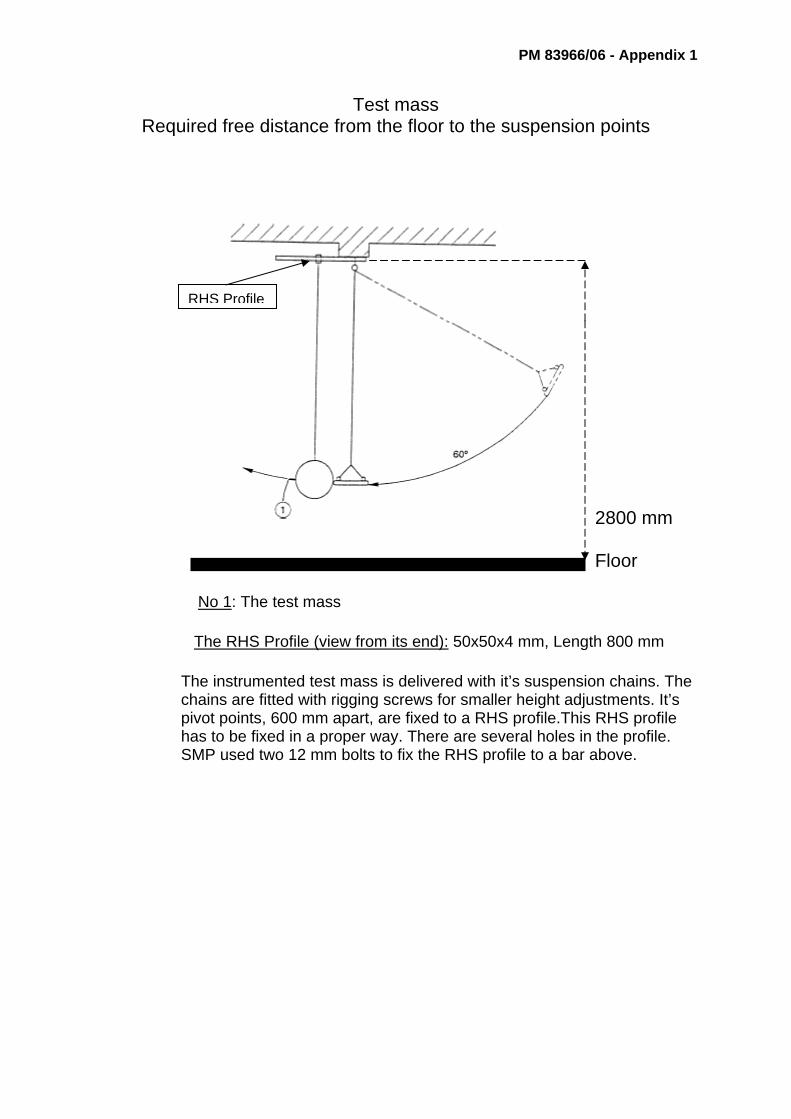
Test mass Required free distance from the floor to the suspension points
2800 mm
Floor No 1: The test mass
The RHS Profile (view from its end): 50x50x4 mm, Length 800 mm
The instrumented test mass is delivered with it’s suspension chains. The chains are fitted with rigging screws for smaller height adjustments. It’s pivot points, 600 mm apart, are fixed to a RHS profile.This RHS profile has to be fixed in a proper way. There are several holes in the profile. SMP used two 12 mm bolts to fix the RHS profile to a bar above.
RHS Profile

PM 83966/06 - Appendix 1
Arrangements at SMP
Delivered RHS Profile

PM 83996/06 - Appendix 2 1
Instruction for Round Robin tests of swing impact General information The objective of the round-robin test is to
- check whether the modification of the methods supplied in EN 71-8 and EN 1176 regarding “impact from swing elements” has resulted in increased repeatability
- obtain information regarding any further possible improvement of the method and the repeatability
Test will be performed at 4 different test-labs in accordance with the instructions below and the enclosures 1 and 2. All equipment except the computer will be sent in advance to each test laboratory and after the tests the same equipment will be sent to the next laboratory in line. SMP will bring the computer and also material for measurement of impact-surface and test-result sheets. SMP’s personnel will not carry out the tests (but will take care of the amplifier and computer) but will be present during the tests in order to observe where more detailed instructions are needed and in order to be able to intervene if there is a risk that any misunderstanding of the instructions may lead to that the test-results cannot be used. Objects to be tested Tests shall be carried out on three different objects;
- Double-swing (seat 1) - Double-swing (seat 2) - Free-hanging swing (seat 3) with two contact surfaces a) and b) (see enclosure 1)
Order of testing I. Seat 1 (Double-swing, seat with blue foam plastic) II. Seat 2 (Double-swing, seat with green foam plastic) III. Seat 3 b) (Free-hanging swing with homogeneous edge) IV. Seat 3 a (Free-hanging swing) Scope of test I. Seat 1 (double-swing): A series of 20 impacts shall be carried out with the aim to have the point of impact in the centre. II: Seat 2 (double-swing): A series of 10 impacts shall be carried out with the aim to have the point of impact in the centre. Furthermore, the impact surface on the seat shall be determined after every single impact. III. Seat 3 b) (free-hanging swing): A series of 25 impacts shall be carried out with the aim to have the point of impact in the centre. The vertical position of the point of impact shall be measured and registered after every single impact. IV. Seat 3 a) (free-hanging swing): Three series of 7 impacts each (total 21) shall be carried out. The aim shall be to have the point of impact 22 (first series), 12 (second series) and 32 mm (third series) below the upper edge of the rubber. The vertical position of the point of impact shall be measured and registered after every single impact.

PM 83996/06 - Appendix 2 2
Preparations 1. Mount the frame for the swing(s) and anchor/fix the planks in a suitable way so that the
frame remains stable/steady throughout the test. 2. Mount seat 1 (double-swing with blue foam plastic) 3. Ensure that the vertical position of the RHS-profile (see enclosure 2) can be adjusted
approx 300 mm vertically in order to allow for the correct height for both swing-types (double-swing and free-hanging swing) to be obtained (there is a 300 mm vertical height difference between the two swing-types)
4. Adjust the test-mass so that the centre of the swing-seat 5. Rig up and arrange the release-device so that the swing can be released at an angle of
60 degrees to the vertical General The acceleration (measured in ”g”) shall be registered with one decimal. The average value for the measured impact-surface (cm2) shall be registered with one decimal. For the free-hanging swing, it shall be secured that the seat surface is perpendicular to its suspension devices when the swing is released. It shall also be secured that the swing performs a continuous pendulum motion without slack in the suspension devices and without the seat swaying in any direction. Before each individual impact, it shall be secured that the test-mass is at complete rest and that it is correctly 3-axially adjusted. Pilot study Prior to the start of each series of measurement, it shall be secured that the intended point of impact is achieved: Mark the centre of the test-mass, (+), with a suitable marker (chalk) so that an imprint is obtained on the impact surface of the seat. Check and, if necessary, make fine adjustments of the test mass in the vertical and horizontal directions. Repeat the procedure until repeatability has been obtained for the intended point of impact. Testing When all adjustments have been made and everything is set for the respective test series, measurements and documentation of each set-up shall be made in accordance with points A-F in enclosure 1 pages 2 - 5. For each impact and test-series, the registered peak acceleration shall be read on the computer and be recorded in the test-result sheet (will be supplied by SMP). Each impact shall also be saved in the computer under individual file-names (will be carried out by SMP). All deviances such as ”impure” or ”slanted” impacts or any other indications that the impact has not been correctly carried out shall be noted in the test-result sheet. In order to avoid that the marking used for measurement of impact-surface (series II, seat 2) will influence the result, chalk shall be used as marker.

PM 83996/06 - Appendix 2 3
Detailed test procedure Procedure • Adjust the swings according the instructions above • Suspend the swing with the means of suspension that has been supplied with the swing
and at the maximum height that these permit • Suspend and adjust the test mass so that the contact points of the swing element and the
centre of the ball are in the same horizontal plane as the centre of gravity of the test mass • Raise the seat along its arc of travel until the side view projection of a straight line through
the pivot point and index mark, forms an angle of 60 degrees to the vertical. Release it so that the swing element collides with the test mass
Support and release of seat Support the seat in the raised position by a mechanism that provides release without the application of external forces which would disturb the trajectory of the suspended member. Ensure that the seat and suspending elements are motionless. Release the seat so that the assembly travels in a smooth downward arc without any visible oscillations or rotations of the seat which would prevent it from striking the test mass at the impact point. Surface compression The exposed impact area (the area of the seat that has made contact with the test mass) shall be measured by applying chalk to the test mass and by measuring the coloured (chalked) surface on the swing element after the impact. Use a transparent celluloid-film (such as that used for OH-projectors) in order to make a copy of the impact-area. Thereafter, place a “millimetre-paper” under the film and calculate the exact area.

9 mm foam plastic
10 mm rubber
14 mm foam plastic
10 mm rubber
10 mm rubber10 mm rubber
10 mm rubber
Seat elements
1
2
3a 3b
Appendix 2- Enkosure 1

A
B
C
D
F
E
Double-seat swing
A B C D E F
mm mm mm mm mm degree
MeasurementsA
Appendix 2 - Enclosure 2
Seat 1

A
B
C
D
F
E
Double-seat swing
A B C D E F
mm mm mm mm mm degree
MeasurementsAppendix 2 -
Appendix 2 - Enclosure 3
Seat 2
A
B
C
D
F
E
Single-seat swing
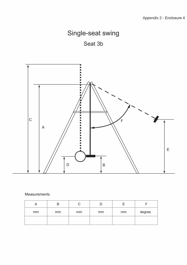
Appendix 2 - Enclosure 4
Seat 3b
A B C D E F
mm mm mm mm mm degree
Measurements

A
B
C
D
F
E
Single-seat swing
Appendix 2 - Enclosure 5
Seat 3a
A B C D E F
mm mm mm mm mm degree
Measurements

REPORT G1/2005
June 2005
EVALUATION AND VALIDATION OF TEST-METHODS AND REQUIREMENTS REGARDING IMPACT FROM SWING-ELEMENTS
S M P S V E N S K M A S K I N P R O V N I N G A B
SMP Uppsala: Fyrisborgsgatan 3, 754 50 Uppsala Tel: 018-56 15 00 Fax: 018-12 72 44 SMP Malmö: Box 56, 230 53 Alnarp Tel: 040-46 44 20 Fax: 040-46 01 13 SMP Umeå: Box 4053, 904 03 Umeå Tel: 090-70 83 70 Fax: 090-13 65 62
E-post: [email protected] Internet: www.smp.nu

CONTENTS 1. Summary ..............................................................................................................2 2. Background ..........................................................................................................3 3. Studies of standards and documents ...................................................................3
3.1. Comparison of existing standards ................................................................3 3.2. Previous discussions regarding EN 1176-2..................................................4 3.3. Revision of EN 1176-2 .................................................................................4
4. Practical evaluation ..............................................................................................4 5. Discussion and conclusions .................................................................................9

52/3/TG 4 N 1 - page 2
1. Summary In connection with a decision in CEN/TC 52 to delete the requirement and test method for “impact from swing elements” from EN 71-8, a task group was asked to look at the requirements and test methods, including a comparison with EN 1176, and validate the test methods and thereafter, if appropriate, propose TC 52/WG 3 to include the method in EN 71-8. This report is part of the group’s task. The project was carried out by SMP Svensk Maskinprovning in Sweden and also included a visit, discussions and some tests at Dansk Teknologisk Institut in Denmark. At SMP some 50 tests were carried out in order to gain an overall impression of the repeatability of the method and to identify factors that have an affect on the test results. Conclusions from the discussions and tests are (regarding EN 71-8): • several improvements to the test method can be made. This will greatly reduce the
variation in test results from different laboratories (this conclusion applies also to EN 1176-2)
• a more precise text and/or a theoretical calculation regarding exemption of certain light swings, which do not have rigid means of suspension, would be helpful in assessing which swings need to be tested. However, if the requirement for surface-compression is introduced in EN 71-8, such a calculation must be combined with an assessment of the impact area
• having made these improvements to the method, it should be possible to validate it by performing round-robin tests according to the revised method at a couple of European test-laboratories and thereafter, if the results are satisfactory, to reintroduce the requirement and method in EN 71-8
• it ought to be possible to design also double-seated swings with rigid means of suspension that pass both the g-value requirement and the surface-compression requirement. This, however, requires resilient material in the seat or in a covering of the seat as well as increased impact area. If it is not possible to adapt these types of swings to the requirements it should be questioned whether they are to be considered safe in the meaning of the toy directive
Furthermore, it is noted in the report that during the revision of EN 1176-2, hardly any changes have been proposed or made to the requirements and test methods regarding impact from swing elements. In Annex 2 to this report, a revised text for the test method and requirements is presented. It is proposed that this Annex 2 is used as a basis for a round-robin test on a voluntary basis, involving e.g. 3 test laboratories from different European countries.
52/3/TG 4 N 1 - page 3
2. Background In EN 1176-2 “Playground equipment – Part 2: Additional specific safety requirements and test methods for swings” requirements and test methods for “impact from swing elements” are given. The requirements and test methods for swing-seats, with an exception for the requirement regarding surface compression, in 1176-2 were copied into the EN 71-8 “Safety of Toys – Part 8: Swings, sides and similar activity toys for indoor and outdoor family domestic use” before the publication of this standard in December 2003. However, the requirements and test methods were questioned by many experts in CEN/TC 52/WG 3 “Safety of Toys – Mechanical and Physical Properties” arguing that the test method had not been validated. At a CEN/TC 52-meeting in Stratford-upon Avon in the following resolution was therefore adopted:
Resolution No 113 (Stratford-upon-Avon, UK, March 2004) Re: Impact from swing elements in EN 71-8 The experts present decided to propose TC 52 to register a new work item according to the UAP procedure proposing to delete clause 4.6.4 "Impact from swing elements" and 6.4 "Determination of impact from swing elements". A task group with experts from Italy (Natale Consonni), Sweden, France, the Netherlands and Germany (Armin Hensel) will look at the requirements and test methods, including a comparison with EN 1176, and validate the test methods. If appropriate they will then propose WG 3 to include this in EN 71-8. The group will choose a convenor among the participants.
Christian Wetterberg, Sweden, has later been appointed convenor of the group. I order to carry out the work of the task group an application for financing of a small project, involving Swedish and Danish test institutes was sent to the Nordic Council who approved the application. The aim of the project was to apply the present test method at two laboratories, one in Denmark and one in Sweden, with the aim to identify any unclear parts of the standard text and thereafter, if possible, to propose improvements to the method.
3. Studies of standards and documents 3.1. Comparison of existing standards
An introductory, theoretical comparison of three standards that include impact-tests for swing elements was made: EN 1176-2, EN 71-8 and ASTM F1148-3. The comparison shows that there are discrepancies between the methods/requirements in the standard. It is notable that the full text from EN 1176-2 has not been implemented in EN 71-8 which is unfortunate since the method is then less precise than the already criticised method in EN 1176-2. On the other hand, the fact that a method for testing impacts from swing-elements has been incorporated both in the American standard for home playground equipment and in the European standard for playground equipment indicates that swings do present a hazard for those children who play in the vicinity of swings that are in use. The comparison also shows that there is room for improvements in the text of the test-method in EN 1176-2. A summary of the comparison is given in Annex 3 of this report. It should be noted that ASTM only covers “single-seat swings” and that EN 71-8 covers also swings for use by more than one child (since they are not specifically exempted).

52/3/TG 4 N 1 - page 4
3.2. Previous discussions regarding EN 1176-2 In connection to the discussion which preceded the adoption of the above resolution No 113, it was also argued that the corresponding requirement and method in EN 1176-2 had been questioned in the responsible committee: CEN/TC 136/SC 1. This is confirmed in two reports from meetings with CEN/TC 136/SC 1: A. Document CEN/TC 136/SC 1 N 459, dated October 30, 2001: Swing Seat Impact Test In 1998 a round robin test was carried out by WG2 to check the consistency of swing seat impact tests. There was found to be a wide variation in results between test houses 34% in the worst case. At a meeting of WG2 in July 1999 it was decided that work should be done to try and make the test more consistent, however with no funding available for test houses to do this work no further progress since that date has been made. The opinion of the leader of WG2 Robin Sutcliffe, is that since the introduction of these tests by DIN and BS there have not been any recorded accidents resulting from impact with swing seats, therefore the need to fund further work does not seem urgent. If SC1 do wish to proceed they will need to obtain funding. B. Document CEN/TC 136/SC 1 N 469, dated December 16, 2001, clause 7.2 b: Swing seat impact test Mr Brady referred to N459 and noted that if further impact tests were required there was a need for some funding. Mr Jensen stated that test houses should ensure that their equipment was in good working order. Mr Settelmeier noted that different results could be obtained if the chain and/or the head forms were changed. There were now a set of 10 tests. Mr Danner stated that although the round robin tests in the early days had shown up big differences, it was much better now. It was agreed that a better defined reproducible test method should be developed during the revision of the standard. It seems that two conclusions can be drawn from the text in the above documents: 1) When the impact test was introduced by DIN and BSI the number of accidents were
reduced 2) It is important that the test method is followed in detail in order for reproducible results
to be obtained.
3.3. Revision of EN 1176-2 EN 1176-2 is presently (2005) under revision and a first draft has been issued. In this first draft only one change of importance has been proposed with regard to the requirements and methods regarding impact from swing-elements. The proposal is that the resulting “Peak-acceleration” shall be calculated as the mean value of 10 peak-acceleration measurements. In the present version of the standard the peak acceleration shall be calculated as the highest reading from any of the 10 performed tests. The fact that the method itself has not been revised in this first draft indicates that the methods and requirements for determination of impact from swing-elements for playground-swings are at present considered to be acceptable and repeatable.
4. Practical evaluation Personnel from SMP visited Dansk Teknologisk Institut (DTI) in Århus, Denmark on February 16, 2005. DTI has long experience from impact-testing according to EN
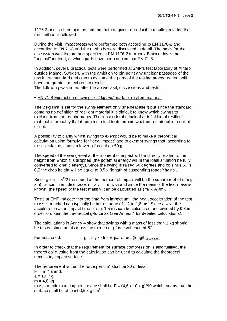
52/3/TG 4 N 1 - page 5
1176-2 and is of the opinion that the method gives reproducible results provided that the method is followed. During the visit, impact-tests were performed both according to EN 1176-2 and according to EN 71-8 and the methods were discussed in detail. The basis for the discussion was the method specified in EN 1176-2 in Annex B since this is the “original” method, of which parts have been copied into EN 71-8. In addition, several practical tests were performed at SMP’s test laboratory at Alnarp outside Malmö, Sweden, with the ambition to pin-point any unclear passages of the text in the standard and also to evaluate the parts of the testing procedure that will have the greatest effect on the results. The following was noted after the above visit, discussions and tests: • EN 71-8 Exemption of swings < 2 kg and made of resilient material The 2 kg limit is set for the swing-element only (the seat itself) but since the standard contains no definition of resilient material it is difficult to know which swings to exclude from the requirements. The reason for the lack of a definition of resilient material is probably that it requires a test to determine whether a material is resilient or not. A possibility to clarify which swings to exempt would be to make a theoretical calculation using formulae for “ideal impact” and to exempt swings that, according to the calculation, cause a lower g-force than 50 g. The speed of the swing-seat at the moment of impact will be directly related to the height from which it is dropped (the potential energy will in the ideal situation be fully converted to kinetic energy). Since the swing is raised 60 degrees and co sinus 60 is 0,5 the drop height will be equal to 0,5 x “length of suspending ropes/chains”. Since g x h = v2/2 the speed at the moment of impact will be the square root of (2 x g x h). Since, in an ideal case, m1 x v1 = m2 x v2 and since the mass of the test mass is known, the speed of the test mass v2 can be calculated as (m1 x v1)/m2. Tests at SMP indicate that the time from impact until the peak acceleration of the test mass is reached can typically be in the range of 1,2 to 1,8 ms. Since a = v/t the acceleration at an impact time of e.g. 1,5 ms can be calculated and divided by 9,8 in order to obtain the theoretical g-force as (see Annex 4 for detailed calculations): The calculations in Annex 4 show that swings with a mass of less than 1 kg should be tested since at this mass the theoretic g-force will exceed 50. Formula used: g = m1 x 45 x Square root (lengthsuspension) In order to check that the requirement for surface compression is also fulfilled, the theoretical g-value from the calculation can be used to calculate the theoretical necessary impact surface. The requirement is that the force per cm2 shall be 90 or less. F = m * a and, a = 10 * g m = 4,6 kg thus, the minimum impact surface shall be F = (4,6 x 10 x g)/90 which means that the surface shall be at least 0,5 x g cm2.

52/3/TG 4 N 1 - page 6
Thus, if g is 50 the impact surface must be 25 cm2. If the impact area is assessed to be smaller, the swing will have to be tested regardless of its weight. Proposal: Exempt swings for which documentation shows that the calculated g-force is lower than 50 and the surface compression is lower than 90 when the above calculations are made. • EN 1176-2, B. 2.2 Test mass
It is not stated in the standard whether a balanced semi-sphere is accepted as a test mass (see example in figure to the left), only that it should be a ball. In practice this semi-sphere is commonly used as test mass since it allows placing of the accelerometer in the centre of gravity of the test mass. The important part of the specification is that the impacting part between the surface struck and the accelerometer shall be homogeneous and free from voids. With regard to the requirement for a very high accuracy of the mass of the test-body (± 0,05 kg) it should be specified whether the accelerometer and any wires shall be included or excluded.
Proposal: Change the specification in order to allow for a balanced semi-sphere to be used as a test mass, provided that it fulfils the requirements regarding mass, dimension of the spherical part, and a homogeneous impacting part. Specify also that the mass shall be within the tolerance when the accelerometer is mounted and that any wires to the accelerometer shall be mounted so that the effect on the mass of the test mass is minimised. • EN 1176-2, B 2.3 Accelerometer and B 3.7 Peak acceleration It is stated in B 2.3 that the accelerometer shall be capable of measuring acceleration triaxially. However, it is not stated in the B 3.7 how the peak acceleration shall be calculated. It can be presumed that the acceleration from one impact shall be calculated as the root-mean-square of the accelerations in the three directions. If not, there is no meaning in requiring an accelerometer which measures triaxially. Furthermore, the proposed change in the first draft for the revision of EN 1176-2 (that the peak acceleration shall be calculated as the mean value of the 10 measurements rather than the highest value of the 10 measurements) has a vital influence on the results. Tests show that the mean value from 10 impacts can differ e.g. 15 % from the highest single value. Since there is a risk that the material in the swing seat is gradually affected by the impact tests, the results may also change. Having regarded the fact that in 4.6.1, it is stated that “there shall be no peak values of acceleration greater than ......” it does not seem correct to start using the mean value when checking fulfilment of this requirement. The requirement for the surface compression, however, is “the average surface compression shall not exceed.....” which is contradictory with the philosophy that the peak value shall be registered. Proposal: Clarify that the peak acceleration from one impact shall be calculated as the root-mean-square of the highest values in each direction of measurement, and

52/3/TG 4 N 1 - page 7
that the highest value from the 10 calculated root-mean-squares shall be used when checking fulfilment of the requirement. • EN 1176-2, B 2.5 Chains The requirement for chains “two 6 mm gauge” is not completely clear. It could mean either that the chain links should have a thickness of material of 6 mm, or that the inner or outer dimension of the chain-link should be 6 mm or that the partition shall be 6 mm. From a testing point of view, the important thing is not the dimension chosen but rather that the specification is unambiguous. The specification in EN 1176-2 is clear regarding how the chains shall be placed and that they shall both connect to the point of connection such that the chains form the letter “V”. However, this specification has not been included in EN 71-8. Proposal: Clarify that the chain links shall have a thickness of material (diameter) of 6 ± 0,5 mm and an outer major dimension of 47 ± 2 mm. • EN 1176-2, B 3.1 and B 3.2 Flat swing seats and cradle seats The means of suspension will affect the result from an impact-test. In EN 1176-2 the text is confusing since in B 3.1 and B 3.2 it is stated that the swings shall hang on 6 mm chains (i.e. not necessarily be suspended by the means of suspension that have been supplied with the swing). However, in Note 1, it is left open whether the swing is suspended by chains or ropes and the impression is therefore that the test can be performed with whatever the swing has been supplied with. For activity toys it is probably best to perform the test using the means of suspension that is supplied together with the swing since they are seldom equipped with 6 mm gauge chains. It should also be specified that the swing shall hang at the maximum height permitted by the means of suspension delivered by the manufacturer. Note: EN 71-8 specifies that the suspended length of the swing device shall be 1 800 mm or as given by the manufacturer. It must be presumed that the length of the suspension connectors of the test mass shall be of approximately the same length but adjusted so that the point of contact will be correct. In EN 1176-2, the suspended length of the swing device is not specified Proposal: Clarify that the tests shall be performed when the swing is suspended with the means of suspension that has been supplied with the swing and at the maximum height that these permit. Another confusing text is that of Note 3. It is allowed to use a brace if the seat material is of a flexible nature. Furthermore, this brace must not have a mass exceeding 10 % of the mass of the seat after test. This text raises two questions: 1. Is it correct to allow an increase of the mass of the swing seat by adding a brace
(a 10 % increase of the mass will affect the result)? 2. Is the mass of the swing expected to change during the test? If not – then why is
the comparison between the mass of the brace made with the mass of the seat after test?
52/3/TG 4 N 1 - page 8
Proposal: Delete the words “after test” in Note 3. Add in the Note that if a brace is used the requirement for maximum 50 g may be increased by the same percentage as the mass increase caused by the brace (which is max 10 %). • EN 1176-2, B 3.8 Surface compression It should be noted that this part of the method has not been included in EN 71-8. The standard is not clear on this point. It must be presumed that the surface compression shall be calculated as the force/area as measured on the test mass (the child’s head/body, which in B 3.9 is inaccurately called the test weight). Therefore, the force F should be calculated as: F = m x a where m is the test mass (4,6 kg) and where a is the peak acceleration measured at the 10 impacts. Furthermore, the surface (area) used in the calculation (F/A where A is the area) should be the exposed area of the test mass which has been hit by the swing. For practical reasons, this area may be measured on the swing seat, for example by colouring the test mass and thereafter measuring the coloured area of the swing seat. It is of great importance that this measurement is made accurately, for example by using millimetre paper. In EN 1176-2, 4.6.1, it is stated that the peak value of the acceleration shall be used for checking fulfilment of the impact-requirement but that the “average surface compression” shall be used for checking fulfilment of the surface-compression requirement. Since this is not very clear it would be better to specify that the area used in the calculation shall be the average of two measurements made when the geometric centre of the seat hits the test mass. This is further explained below under the point “Contact point of test mass and swing seat”. The figure in EN 1176-2, B 3.9 shows a flat seat when raised to the 60 º position. It could be a help if the figure also showed a double-seat swing raised to the 60 º position. Proposal: Clarify in B 3.8 how the exposed area shall be measured and that the compression shall be calculated as F/A where F = m * a, where “m” is test mass and “a” is the peak acceleration of the test mass in a single impact test. Specify that the area shall be measured twice when the geometric centre of the leading edge of the swing seat hits the test mass (see also “Contact point of test mass and swing seat”). Complete the figure in B 3.9 with a double-seat swing raised to the 60 º position. • EN 1176-2 and EN 71-8, Accuracy It is not clear with what accuracy the various measurements shall be made. In EN 71-8, for example, the requirement is that the impact shall not exceed “500 m/s2 (or 50 g)”. If g is set to 9,81 m/s2, 50 g corresponds to 490 m/s2. Proposal: Clarify, where necessary, the required accuracy of measuring equipment and measurements. •

52/3/TG 4 N 1 - page 9
EN 1176-2 and EN 71-8 Contact point of test mass and swing seat It should be obvious to all testers that the swing seat shall hit the test mass at a point which lies along a horizontal line through the centre of gravity of the test mass (even though the text in EN 1176-2, B 3.3 is not very clear). It is, however, not clearly specified which part of the swing seat that shall hit this point of the test mass. The leading edge of the swing seat will always have a certain height and tests show that the results can vary up to 10 % depending on the height adjustment of the swing. It would therefore seem logical to perform the first two impact tests so that geometric centre of the leading edge hits the test mass, and thereafter to adjust the height of the test mass during the remaining 8 impact tests so that the tests cover also the most onerous point (highest g-force) of impact on the swing seat. When assessing the surface compression it would be appropriate to use the average area measured during the first two impact test, i.e. when the geometric centre of the leading edge hits the test mass. Proposal: Specify that: - during the impact-measurements the first two tests shall be performed with the
seat adjusted so that the geometric centre of the leading edge hits the test mass at a point along the horizontal line through the centre of gravity of the test-mass
- that the average impact area measured during this two tests shall be used for calculation of surface compression
- that the remaining 8 impact tests shall be made with the test mass adjusted to various height so as to cover the most onerous (highest g-value) point of impact on the swing seat
• EN 1176-2 and EN 71-8 Impact from other parts of the swing
It should be noted that for, for example, a double-seat swing (as shown in the figure) also other parts than the seat could hit a passing child. The foot-rests, for example, would present a higher risk of injury than the seat itself since the material is non-resilient and since the area of contact is much smaller. Proposal: No action at present but should bdiscussed for the future. Perhaps a requirement for resilient, protective material on parts that could hit a child could be appropriate?
e
5. Discussion and conclusions At SMP, some 50 impact tests have been carried out on a flat-seat swing and a double-seat swing, both for domestic use. The tests did not aim specifically at determining the impact (g-force) for the individual samples, but rather to give an

52/3/TG 4 N 1 - page 10
overall impression of the repeatability of the method and to identify factors that have an affect on the test results. Therefore, the data from the tests have not been included in this report.
It was quite clear from the tests that the flat-seat swing caused g-forces which were well below the requirement (approximately 10- 15 g). The seat weighed 300 g but since it was not clear whether the material was to be considered as “resilient” the swing was considered to be encompassed by the requirements in EN 71-8. The double-seat swing weighed 3 780 g including the two rigid suspension connectors. A type of swing which probably more often fails the requirements in the impact tests is the double-seat swing. The measured g-value in tests with the double-seat swing varied from approximately 50 g to 80 g depending on the height adjustment of the seat. A general opinion that has been expressed by experts in the field is that the above type of double-seat swings will always fail the impact test. However, the tests at SMP show that the result is highly affected by the type of material in the seat. In order to study (on a very basic level) the effect of various resilient materials, three different types of rubber-material were fastened to the leading edge of the seat and the tests were repeated.
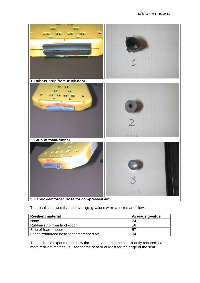
52/3/TG 4 N 1 - page 11
1. Rubber-strip from truck-door
2. Strip of foam-rubber
3. Fabric-reinforced hose for compressed air The results showed that the average g-values were affected as follows: Resilient material Average g-value None 74 Rubber-strip from truck-door 58 Strip of foam-rubber 57 Fabric-reinforced hose for compressed air 34 These simple experiments show that the g-value can be significantly reduced if a more resilient material is used for the seat or at least for the edge of the seat.

52/3/TG 4 N 1 - page 12
On the other hand, since the exposed impact area of the seat (without addition of resilient material) was approximately 8 cm2, a reduction of the g-force to 35 will not be enough to fulfil the requirement of max. 90 N/cm2 surface compression. Given that the exposed impact area remains the same for a resilient seat, the impact area would need to be at least approx. 16 cm2: F = m * a where, m = 4,6 kg, and a = 9,81 * 35 thus, F = 1 579 N and 1 579/90 = 15,5 cm2. If the total weight of the swing cannot be reduced (in order to achieve a further reduced g-value) the seat would need to be more resilient and the impact area would need to be increased if both requirements are to be fulfilled (g-value and surface compression). Some conclusions regarding swings for domestic use: • several improvements to the test method can be made. This will greatly reduce the
variation in test results from different laboratories (this conclusion applies also to EN 1176-2)
• a more precise text and/or a theoretical calculation regarding exemption of certain light swings, which do not have rigid means of suspension, would be helpful in assessing which swings need to be tested. However, if the requirement for surface-compression is introduced in EN 71-8, such a calculation must be combined with an assessment of the impact area
• having made these improvements to the method, it should be possible to validate it by performing round-robin tests according to the revised method at a couple of European test-laboratories and thereafter, if the results are satisfactory, to reintroduce the requirement and method in EN 71-8
• it ought to be possible to design also double-seated swings with rigid means of suspension that pass both the g-value requirement and the surface-compression requirement. This, however, requires resilient material in the seat or in a covering of the seat as well as increased impact area. If it is not possible to adapt these types of swings to the requirements it should be questioned whether they are to be considered safe in the meaning of the toy directive
ANNEXES 1. Pictures from impact test of a double-seat swing with rigid suspension 2. Proposal for a revised text for requirements and test-methods regarding impact
from swing elements 3. A comparison of three standards (EN 71-8, EN 1176-2 and ASTM F1148-3) 4. Calculations


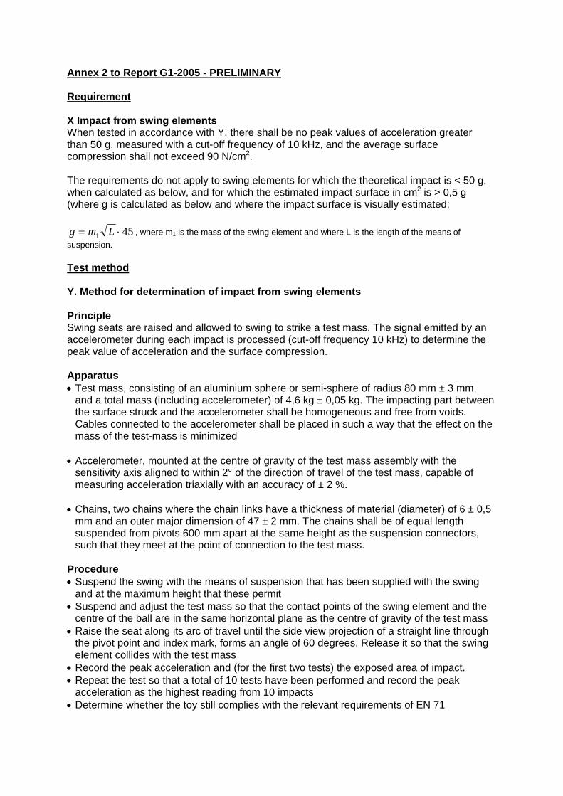
Annex 2 to Report G1-2005 - PRELIMINARY Requirement X Impact from swing elements When tested in accordance with Y, there shall be no peak values of acceleration greater than 50 g, measured with a cut-off frequency of 10 kHz, and the average surface compression shall not exceed 90 N/cm2. The requirements do not apply to swing elements for which the theoretical impact is < 50 g, when calculated as below, and for which the estimated impact surface in cm2 is > 0,5 g (where g is calculated as below and where the impact surface is visually estimated;
451 ⋅= Lmg , where m1 is the mass of the swing element and where L is the length of the means of suspension. Test method Y. Method for determination of impact from swing elements Principle Swing seats are raised and allowed to swing to strike a test mass. The signal emitted by an accelerometer during each impact is processed (cut-off frequency 10 kHz) to determine the peak value of acceleration and the surface compression. Apparatus • Test mass, consisting of an aluminium sphere or semi-sphere of radius 80 mm ± 3 mm,
and a total mass (including accelerometer) of 4,6 kg ± 0,05 kg. The impacting part between the surface struck and the accelerometer shall be homogeneous and free from voids. Cables connected to the accelerometer shall be placed in such a way that the effect on the mass of the test-mass is minimized
• Accelerometer, mounted at the centre of gravity of the test mass assembly with the
sensitivity axis aligned to within 2° of the direction of travel of the test mass, capable of measuring acceleration triaxially with an accuracy of ± 2 %.
• Chains, two chains where the chain links have a thickness of material (diameter) of 6 ± 0,5
mm and an outer major dimension of 47 ± 2 mm. The chains shall be of equal length suspended from pivots 600 mm apart at the same height as the suspension connectors, such that they meet at the point of connection to the test mass.
Procedure • Suspend the swing with the means of suspension that has been supplied with the swing
and at the maximum height that these permit • Suspend and adjust the test mass so that the contact points of the swing element and the
centre of the ball are in the same horizontal plane as the centre of gravity of the test mass • Raise the seat along its arc of travel until the side view projection of a straight line through
the pivot point and index mark, forms an angle of 60 degrees. Release it so that the swing element collides with the test mass
• Record the peak acceleration and (for the first two tests) the exposed area of impact. • Repeat the test so that a total of 10 tests have been performed and record the peak
acceleration as the highest reading from 10 impacts • Determine whether the toy still complies with the relevant requirements of EN 71

NOTE 1: When the seat is suspended from ropes or chains etc, some curvature will be produced in the suspending elements. Adjust the seat position to determine the curvature which provides a stable trajectory. NOTE 2: Caution should be exercised to prevent damage to the test equipment. Where there is any possibility of the accelerometer range being exceeded, preliminary tests should be made at lower angles (e.g. 10 , 20 and 30 degrees). If there is doubt concerning the seat trajectory or stability, the test mass and/or guidance structure trial releases should be made without impacting the test mass. NOTE 3: Some seats of a flexible nature will require a brace to maintain the seat configuration during the test procedure. The mass of brace should not exceed 10 % of the mass of the seat. If a brace is used, the requirement for maximum 50 g may be increased by the same percentage as the mass increase caused by the brace (max 10 %) Support and release of seat Support the seat in the raised position by a mechanism that provides release without the application of external forces which would disturb the trajectory of the suspended member. Ensure that the seat and suspending elements are motionless. Release the seat so that the assembly travels in a smooth downward arc without any visible oscillations or rotations of the seat which would prevent it from striking the test mass at the impact point. Impact tests Once satisfactory system operation and calibration are obtained, collect data from ten impacts. The first two impact tests shall be performed with the seat adjusted so that the geometric centre of the leading edge hits the test mass at a point along the horizontal line through the centre of gravity of the test-mass. The remaining 8 impact tests shall be made with the test mass adjusted to various height so as to cover the most onerous (highest g-value) point of impact on the swing seat Surface compression The average exposed impact area (the area of the seat that has made contact with the test weight) shall be measured with an accuracy of ± 5 % during the first two impact tests. The mean of these two measurements shall be used for calculation of surface compression and for checking of fulfilment of the surface-compression requirement. NOTE: The ± 5 % accuracy can be obtained by the application of colour to the test mass and by measuring the coloured surface on the swing element after the impact. The surface shall be measured using transparent “millimetre-paper”. Calculate the surface compression in N/cm2 using the formula F/A where F = m * a, and where: “m” is the test mass (4,6 kg ± 5 %), and “a” is the highest, single peak acceleration-value measured during the 10 impact tests. Peak acceleration Measure the peak acceleration for each impact (total 10 impacts). The peak acceleration from one impact shall be calculated as the root-mean-square of the highest values in each direction of measurement “SQR (X2+Y2+Z2)”. The highest value from the 10 calculated root-mean-squares shall be used when checking fulfilment of the requirement for maximum impact. Figure: Figure of test set-up to be completed with double swing
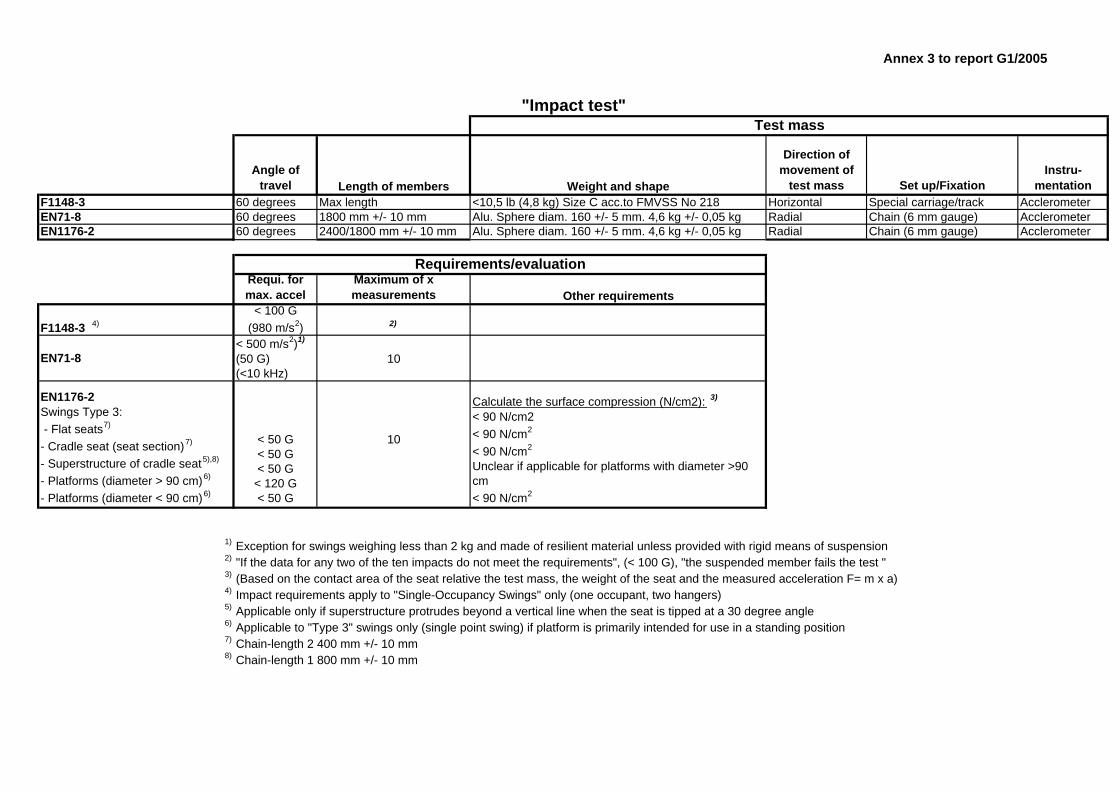
Annex 3 to report G1/2005
"Impact test"Test mass
Angle of travel Length of members Weight and shape
Direction of movement of
test mass Set up/FixationInstru-
mentationF1148-3 60 degrees Max length <10,5 lb (4,8 kg) Size C acc.to FMVSS No 218 Horizontal Special carriage/track AcclerometerEN71-8 60 degrees 1800 mm +/- 10 mm Alu. Sphere diam. 160 +/- 5 mm. 4,6 kg +/- 0,05 kg Radial Chain (6 mm gauge) AcclerometerEN1176-2 60 degrees 2400/1800 mm +/- 10 mm Alu. Sphere diam. 160 +/- 5 mm. 4,6 kg +/- 0,05 kg Radial Chain (6 mm gauge) Acclerometer
Requirements/evaluationRequi. formax. accel
Maximum of x measurements Other requirements
F1148-3 4)< 100 G
(980 m/s2) 2)
EN71-8< 500 m/s2)1)
(50 G) (<10 kHz)
10
EN1176-2Swings Type 3: - Flat seats7)
- Cradle seat (seat section)7)
- Superstructure of cradle seat5),8)
- Platforms (diameter > 90 cm)6)
- Platforms (diameter < 90 cm)6)
< 50 G< 50 G< 50 G
< 120 G< 50 G
10
Calculate the surface compression (N/cm2): 3)
< 90 N/cm2< 90 N/cm2
< 90 N/cm2
Unclear if applicable for platforms with diameter >90 cm< 90 N/cm2
1) Exception for swings weighing less than 2 kg and made of resilient material unless provided with rigid means of suspension2) "If the data for any two of the ten impacts do not meet the requirements", (< 100 G), "the suspended member fails the test "3) (Based on the contact area of the seat relative the test mass, the weight of the seat and the measured acceleration F= m x a)4) Impact requirements apply to "Single-Occupancy Swings" only (one occupant, two hangers)5) Applicable only if superstructure protrudes beyond a vertical line when the seat is tipped at a 30 degree angle6) Applicable to "Type 3" swings only (single point swing) if platform is primarily intended for use in a standing position7) Chain-length 2 400 mm +/- 10 mm8) Chain-length 1 800 mm +/- 10 mm
Annex 3 to report G1/2005
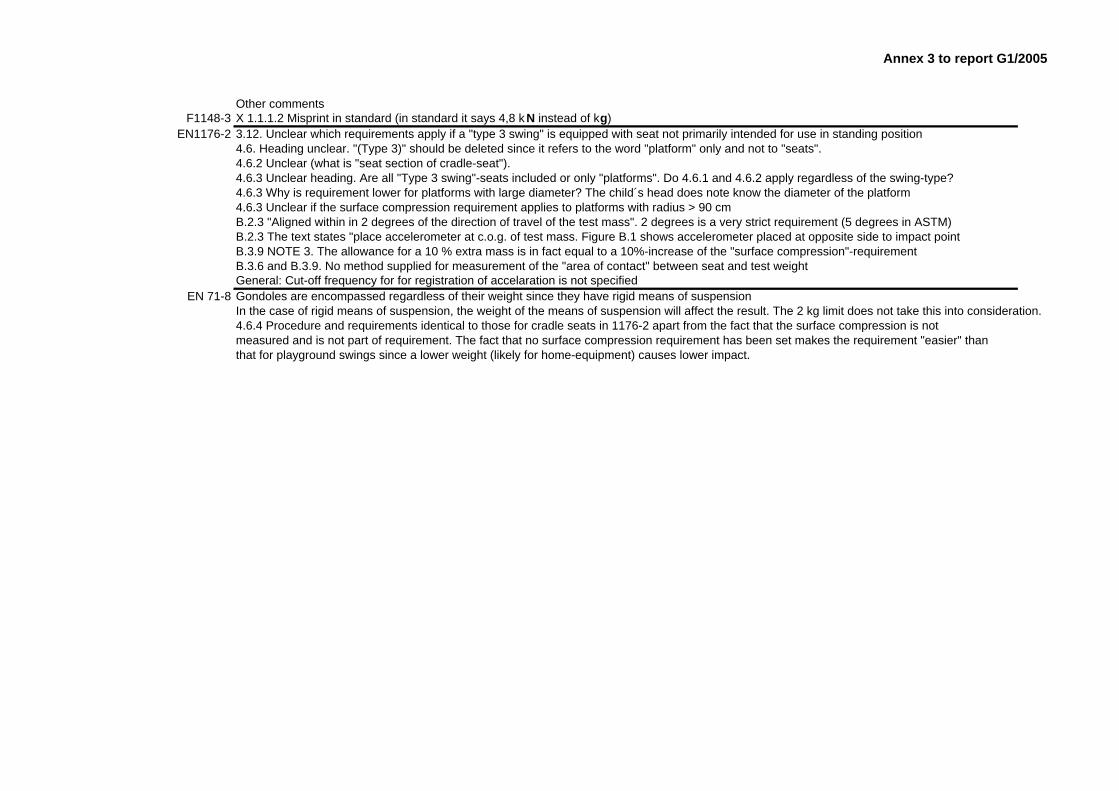
Other commentsF1148-3 X 1.1.1.2 Misprint in standard (in standard it says 4,8 k N instead of kg)
EN1176-2 3.12. Unclear which requirements apply if a "type 3 swing" is equipped with seat not primarily intended for use in standing position4.6. Heading unclear. "(Type 3)" should be deleted since it refers to the word "platform" only and not to "seats".4.6.2 Unclear (what is "seat section of cradle-seat").4.6.3 Unclear heading. Are all "Type 3 swing"-seats included or only "platforms". Do 4.6.1 and 4.6.2 apply regardless of the swing-type?4.6.3 Why is requirement lower for platforms with large diameter? The child´s head does note know the diameter of the platform4.6.3 Unclear if the surface compression requirement applies to platforms with radius > 90 cmB.2.3 "Aligned within in 2 degrees of the direction of travel of the test mass". 2 degrees is a very strict requirement (5 degrees in ASTM)B.2.3 The text states "place accelerometer at c.o.g. of test mass. Figure B.1 shows accelerometer placed at opposite side to impact point B.3.9 NOTE 3. The allowance for a 10 % extra mass is in fact equal to a 10%-increase of the "surface compression"-requirementB.3.6 and B.3.9. No method supplied for measurement of the "area of contact" between seat and test weightGeneral: Cut-off frequency for for registration of accelaration is not specified
EN 71-8 Gondoles are encompassed regardless of their weight since they have rigid means of suspensionIn the case of rigid means of suspension, the weight of the means of suspension will affect the result. The 2 kg limit does not take this into consideration.4.6.4 Procedure and requirements identical to those for cradle seats in 1176-2 apart from the fact that the surface compression is notmeasured and is not part of requirement. The fact that no surface compression requirement has been set makes the requirement "easier" than that for playground swings since a lower weight (likely for home-equipment) causes lower impact.

ANNEX 4 to report G1-2005 Assume that the centre of gravity of the swing coincides with the geometrical centre of the swing seat. In that case the drop height of the mass will correspond to co sinus 60 (= 0,5) of the length of the suspension connectors.
Energy: 2
2mvmgh = ⇔ Lgv 5,02= ⇔ Lv 10≈ = the speed of the swing at the moment of impact
Ideal impact: . Therefore, the speed of the test-mass after impact will be: 2211 vmvm =
2
1
2
112
10m
Lmm
vmv ==
Also: 22va = and . Therefore, 10≈g
tvg10
2= where t is the time from impact to peak acceleration.
Thus: tmLmg
2
1
1010
= m2 = test mass = 4,6 kg.
t = 1,5 ms (estimated from practical tests)
Thus: 45105,16,410
1013
1 ⋅≈⇒⋅⋅⋅
= − LmgLm
g
For surface compression the requirement is that F/ impact surface < 90 N / cm2
Since and amF ⋅= 2 10⋅≈ ga the minimum impact surface will be 90
102 ⋅⋅ gm where g is the measured g-
value in the test.. Since m2 is 4,6 kg the surface must be > 4,6 * 100/90 = approx 0,5 g If the length L is 1,5 metres g will be approx. 50 when m1 = 1 kg. The conclusion would be that swings of a mass of less than approx. 1 kg have to be tested. However, even if the mass is less than 1 kg, the swing in question would have to be tested if the estimated impact surface is less than 0,5 (g*0,5) cm2 (minimum 25 cm2 if measured g = 50, minimum 12,5 cm2 if measured g = 25 etc.)


PM 83996/06 - Appendix 6
Proposal for revised requirements and test method for “Impact from swing elements” in EN 71-8 Definitions Add a definition: 3.x impact area the area of the swing seat that comes in contact with the test mass during an impact test Consider revising the definition of swing (see e.g. 1176-2). Requirement X Impact from swing elements When tested in accordance with Y, swing elements shall not impart an average peak acceleration (average calculation to be based on the 5 specified measurements) peak values of acceleration, measured with a cut-off frequency of 10 kHz, shall not be greater than 50 g, and the average of the two measured values of surface compression shall not be greater than 90 N/cm2. The requirements do not apply to swing elements weighing less than 1,0 kg, including the weight of the means of suspension as defined in figure x (diagrammatic representation f a swing) and for which the estimated impact area is larger than 20 cm2. Test method Y. Method for determination of impact from swing elements Principle Swing seats are raised and allowed to swing to strike a test mass. The signal emitted by an accelerometer during each impact is processed (cut-off frequency 10 kHz) to determine the peak value of acceleration. The impact area between the swing and the test mass is measured and the surface compression is calculated . Apparatus • Test mass, consisting of an aluminium sphere or semi-sphere of radius 80 mm ± 3 mm,
and a total mass (including accelerometer) of 4,6 kg ± 0,05 kg. The impacting part between the surface struck and the accelerometer shall be homogeneous and free from voids. Cables connected to the accelerometer shall be placed in such a way that the effect on the mass of the test-mass is minimized (for example of a test-mass design, see figure X1)
• Accelerometer, mounted at the centre of gravity of the test mass assembly with the sensitivity axis aligned to within 2° of the direction of travel of the test mass, capable of measuring acceleration triaxially in the range of ± 500 g with an accuracy of ± 0,1 g and with a frequency range from 0 to 10 000 Hz.
• Amplifier, with a sampling frequency of 10 kHz and a cut-off frequency of 10 kHz • Two chains where the chain links have a thickness of material (diameter) of 6 ± 0,5 mm
and an outer major dimension of 47 ± 2 mm. The chains shall be of equal length suspended from pivots 600 mm apart at the same height as the suspension connectors, such that they meet at the point of connection to the test mass. The fictive prolongations of the chains shall meet in the centre of the test-mass (see figure X1).
PM 83996/06 - Appendix 6
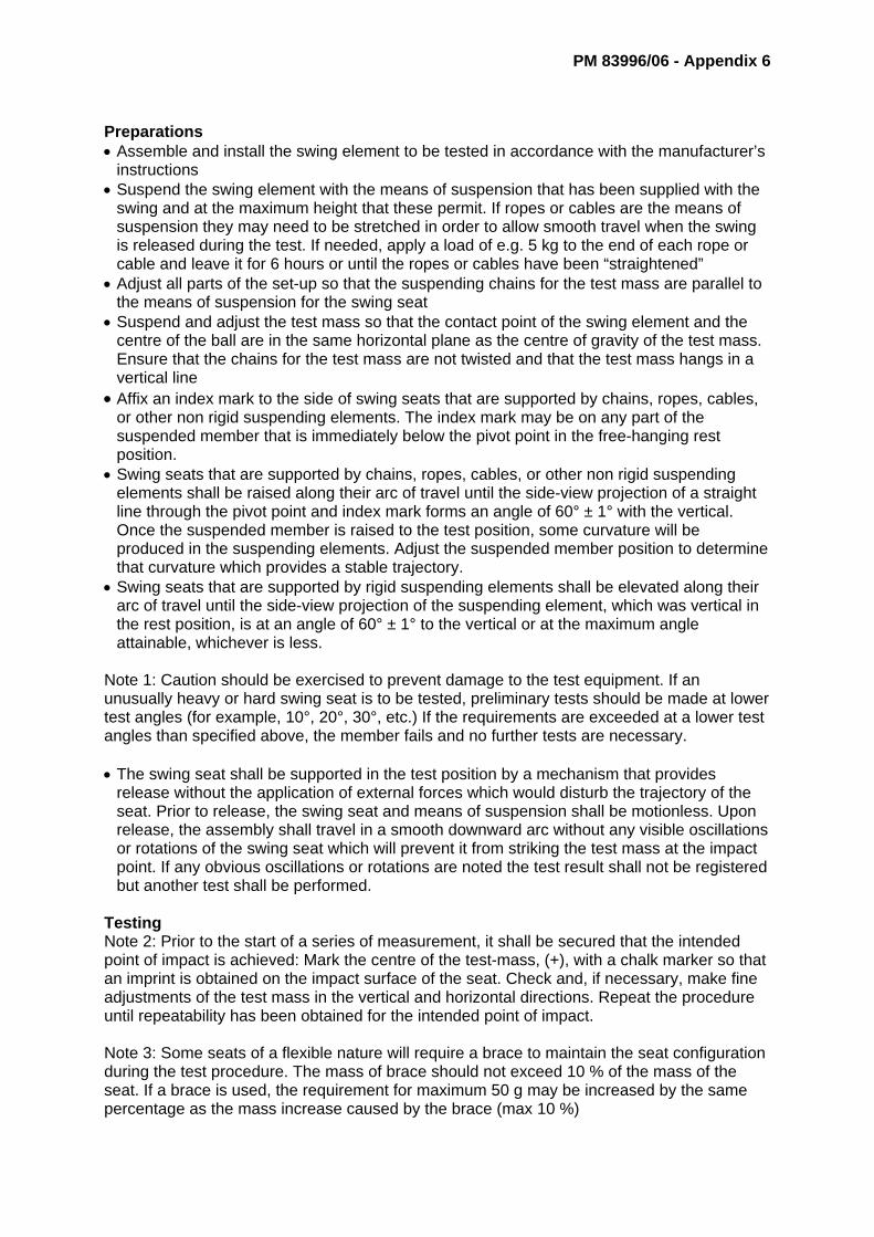
Preparations • Assemble and install the swing element to be tested in accordance with the manufacturer’s
instructions • Suspend the swing element with the means of suspension that has been supplied with the
swing and at the maximum height that these permit. If ropes or cables are the means of suspension they may need to be stretched in order to allow smooth travel when the swing is released during the test. If needed, apply a load of e.g. 5 kg to the end of each rope or cable and leave it for 6 hours or until the ropes or cables have been “straightened”
• Adjust all parts of the set-up so that the suspending chains for the test mass are parallel to the means of suspension for the swing seat
• Suspend and adjust the test mass so that the contact point of the swing element and the centre of the ball are in the same horizontal plane as the centre of gravity of the test mass. Ensure that the chains for the test mass are not twisted and that the test mass hangs in a vertical line
• Affix an index mark to the side of swing seats that are supported by chains, ropes, cables, or other non rigid suspending elements. The index mark may be on any part of the suspended member that is immediately below the pivot point in the free-hanging rest position.
• Swing seats that are supported by chains, ropes, cables, or other non rigid suspending elements shall be raised along their arc of travel until the side-view projection of a straight line through the pivot point and index mark forms an angle of 60° ± 1° with the vertical. Once the suspended member is raised to the test position, some curvature will be produced in the suspending elements. Adjust the suspended member position to determine that curvature which provides a stable trajectory.
• Swing seats that are supported by rigid suspending elements shall be elevated along their arc of travel until the side-view projection of the suspending element, which was vertical in the rest position, is at an angle of 60° ± 1° to the vertical or at the maximum angle attainable, whichever is less.
Note 1: Caution should be exercised to prevent damage to the test equipment. If an unusually heavy or hard swing seat is to be tested, preliminary tests should be made at lower test angles (for example, 10°, 20°, 30°, etc.) If the requirements are exceeded at a lower test angles than specified above, the member fails and no further tests are necessary. • The swing seat shall be supported in the test position by a mechanism that provides
release without the application of external forces which would disturb the trajectory of the seat. Prior to release, the swing seat and means of suspension shall be motionless. Upon release, the assembly shall travel in a smooth downward arc without any visible oscillations or rotations of the swing seat which will prevent it from striking the test mass at the impact point. If any obvious oscillations or rotations are noted the test result shall not be registered but another test shall be performed.
Testing Note 2: Prior to the start of a series of measurement, it shall be secured that the intended point of impact is achieved: Mark the centre of the test-mass, (+), with a chalk marker so that an imprint is obtained on the impact surface of the seat. Check and, if necessary, make fine adjustments of the test mass in the vertical and horizontal directions. Repeat the procedure until repeatability has been obtained for the intended point of impact. Note 3: Some seats of a flexible nature will require a brace to maintain the seat configuration during the test procedure. The mass of brace should not exceed 10 % of the mass of the seat. If a brace is used, the requirement for maximum 50 g may be increased by the same percentage as the mass increase caused by the brace (max 10 %)

PM 83996/06 - Appendix 6
The intended point of impact is defined as the geometrical centre of the impact surface of the swing. • Mark the centre of the test-mass, (+), with a chalk marker so that an imprint is obtained on
the impact surface of the seat. • Ensure that the test-mass is at complete rest and that it is correctly 3-axially adjusted. • Elevate the seat and release it as specified above so that the swing element collides with
the test mass. • Check that the imprint on the impact surface of the seat lies within ± 5 mm (vertical
direction) and ± 10 mm (horizontal direction) from the intended point of impact. • Collect data from 5 impacts (free from obvious oscillations or rotations). Measure the peak
acceleration in g for each impact. Calculate the average peak acceleration and check whether the requirement is met. The peak acceleration from one impact shall be calculated as the root-mean-square of the highest values in each direction of measurement: SQR[(max X)2+(max Y)2+(max Z)2]. Note that the maximum value in each direction shall be measured regardless of at which time it occurs (max X may occur at a different moment than max Y)
• In two of the five impact tests, the impact area shall be measured as follows. Apply chalk to the test mass before the impact test and measure the chalked surface on the swing element after the impact. Use a transparent celluloid-film (such as that used for OH-projectors) in order to make a copy of the impact-area. Thereafter, place a “millimetre-paper” under the film and calculate the exact area. Calculate the average impact area for the two tests and thereafter the surface compression in N/cm2 using the formula F/A where F = m * a, and where:
“m” is the test mass (4,6 kg ± 5 %), and “a” is the average peak acceleration-value calculated from the 5 impact tests
Note 4: If the swing is deformed during testing, a new sample shall be used for the remaining tests. Note 5: It may be necessary to clean the test mass with spirits and to General • The acceleration in ”g” shall be registered with one decimal. • The average value for the measured impact-surface (cm2) shall be registered with one
decimal.
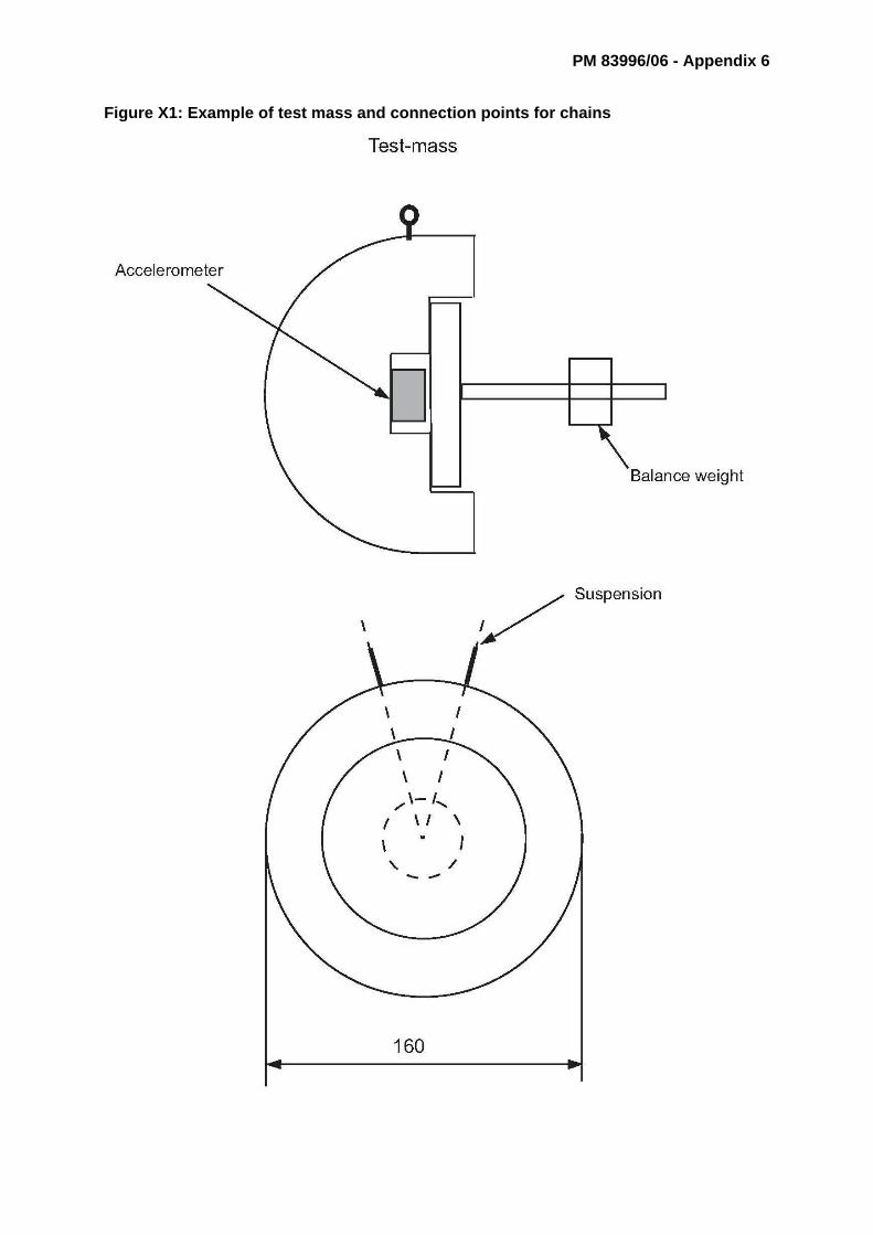
PM 83996/06 - Appendix 6
Figure X1: Example of test mass and connection points for chains

APPENDIX 7 to PM 83996/06
IMPACT FROM SWING ELEMENTSRound Robin 2006
Test serie I Type of seat Point of impact
Seat 1 Centre
Measu -red *)
Devia- tion **)
Measu -red *)
Devia- tion **)
Measu -red *)
Devia- tion **)
Measu -red *)
Devia- tion **)
Measu -red *)
Devia- tion **)
1 57,1 54,3 58,1 16 1+ 61,7 14 0 57,42 56,3 54,7 57,6 20 3- 59,9 13,5 0 593 56,3 54,3 56,8 21 4- 59,8 17 0 56,14 57,5 55,0 55,3 19 2- 59,5 16 0 56,75 56,3 55,8 56,2 20 3- 58,8 16,5 0 55,26 57,8 54,8 55,9 19 2- 59,4 14,5 0 567 58,1 54,9 57,9 19 2- 58,1 16 0 54,68 59,3 55,0 54,9 18 1- 58,7 17 0 54,89 57,5 53,5 59,4 19 2- 58,7 15,5 0 55,510 57,5 54,9 55,8 20 3- 59,3 15,5 0 55,511 54,5 57,2 19 2- 58,2 16,5 0 56,712 54,9 56,5 18 1- 57 17 0 54,513 54,9 54,5 18 1- 58,7 14,5 0 55,314 54,3 54,4 20 3- 57,7 16,5 0 54,515 54,2 58,3 17 0 57,2 16,5 0 56,916 54,7 54,3 19 2- 57,9 16,5 0 57,617 54,6 55,1 20 3- 57,2 15 0 5418 54,5 56 18 1- 57,7 15,5 0 5419 54,6 54,9 17 0 56,6 17,5 0 53,120 55,3 58,3 18 1- 57,5 16,5 0 56,5 MAX (ave) 58,48
57,37 54,69 56,37 58,48 55,70 MIN (ave) 54,69Deviation 6,9%
*) Distance measured from the upper edge of the rubber**) Above + and - below
Swed
en
Finl
and
Italy
Fran
ce
Swed
en II
Average 57,4 54,69 56,37 58,48 55,70Min: 56,3 53,5 54,3 56,6 53,1 MIN 53,1Max. 59,3 55,8 59,4 61,7 59,0 MAX 61,7Deviation Min-Max: 5,3% 4,3% 9,4% 9,0% 11,1% Dev 16,2%
Min: 57,1 54,2 54,4 57,2 54 MIN 54,0Max. 57,8 55,3 58,3 59,9 57,6 MAX 59,9Deviation Min-Max: 1,2% 2,0% 7,2% 4,7% 6,7% Dev 10,9%
Excluding Min-Maxof the 20 impacts:
Sweden II
Measu- red value
g
Point of impact, mm
Deviation from
horizontal line, mm
France
Measu- red value
g
Testno:
Measu- red value
g
Measu- red value
g
Type of swing
Double-seat
Point of impact, mm
Deviation from
horizontal line, mm
Sweden Finland Italy
Point of impact, mm Deviation from
horizontal line, mm
Point of impact, mm
Point of impact, mm
Deviation from
horizontal line, mm
Deviation from
horizontal line, mm
Measu- red value
g

IMPACT FROM SWING ELEMENTS *) Distance measured from the upper edge of the rubberRound Robin 2006 **) Above + and - below
***) The area determined by weighingTest serie II Type of swing Type of seat Point of impact
Double-seat Seat 2 Centre
Measu -red *)
Devia- tion **)
Measu -red *)
Devia- tion **)
Measu -red *)
Devia- tion **)
Measu -red *)
Devia- tion **)
Measu -red *)
Devia- tion **)
101 48,1 28,7 76,0 45,7 26,5 78,2 50,5 -- 28,0 81,7 45,6 24,8 83,3 44,4102 48,1 28,4 76,8 46,6 26,8 78,8 45,5 -- 27,1 76,1 50,0 26,5 85,5 45,6103 49,3 28,6 78,1 47,4 26,8 80,2 48,7 -- 27,6 80,0 50,9 26,8 86,1 45,2104 49,0 27,7 80,2 47,9 27,4 79,2 50,4 -- 27,9 81,9 50,5 26,3 87,0 45,8105 49,6 28,3 79,4 47,7 27,5 78,6 47,2 -- 27,1 78,9 50,6 26,2 87,5 46,6106 50,0 27,9 81,2 47,6 27,3 79,0 46,2 -- 27,6 75,9 49,7 25,3 89,0 47,5
10749,1 27,4 81,2
47,0Yta ej säker 27,4
77,7 50,7 -- 27,0 85,1 51,0 26,5 87,2 46,8
108 50,3 27,4 83,2 45,9 Sne 27,6 75,4 48,4 -- 27,2 80,6 50,2 25,3 89,9 50,2109 50,3 27,6 82,6 47,7 27,6 78,3 48,6 -- 27,9 78,9 49,7 25,8 87,3 45,7110 49,5 27,5 81,6 47,4 27 79,6 52,7 -- 27,3 87,5 50,1 26,1 87,0 48,2
49,3 28,0 80,0 47,1 27,2 78,5 48,9 27,5 80,7 49,83 26,0 87,0 46,6 MIN 46,6 27,2 78,5SWEDEN ll MAX 49,83 28,0 80,7
g Area Comp Dev 6,9% 2,8% 2,8%
MIN 44,4 24,8 75,4 incl FRMin: 48,1 27,4 76,0 45,7 26,5 75,4 45,5 27,0 75,9 45,6 24,8 83,3 44,4 MAX 52,7 28,7 89,9 incl FRMax. 50,3 28,7 83,2 47,9 27,6 80,2 52,7 28,0 87,5 51,0 26,8 89,9 50,2 Devia 18,7% 15,7% 19,3% incl FRDeviation Min-Max: 4,6% 4,7% 9,5% 4,8% 4,2% 6,4% 15,8% 3,7% 15,3% 11,8% 8,1% 7,9% 13,1% MIN 26,5 75,4 Excl. FR
MAX 28,7 87,5 Excl. FRDevia 8,3% 16,1% Excl. FR
Excluding Min-Maxof the 10 impacts: MIN 45,2 25,3 76,1 incl FRMin: 49,0 27,5 76,8 45,9 26,8 77,7 46,2 27,2 76,1 49,7 25,3 85,5 45,2 MAX 50,9 28,6 89,0 incl FRMax. 50,0 28,6 82,6 47,4 27,6 79,6 50,7 27,9 85,1 50,9 26,5 89 48,2 Dev 12,6% 13,0% 17,0% incl FRDeviation Min-Max: 2,0% 4,0% 7,6% 3,3% 3,0% 2,4% 9,7% 2,6% 11,8% 2,4% 4,7% 4,1% 6,6% MIN 26,8 76,1 Excl. FR
MAX 28,6 85,1 Excl. FRDev 6,7% 11,8% Excl. FR
Average 10 impacts
SWEDEN FINLAND ITALY
Area
cm2
Surface
compression
N/cm
2
Measured value
g
Measured value
g
Area
cm2
Surface
compression
N/cm
2
FRANCE
Areacm2
***)
France
Measu-red
valueg
Surfacecompression
N/cm2
Areacm2
Sweden Finland Italy
Point of impact, mm Surfacecompressi
onN/cm2
Testno:
Measu- red
valueg
Measu- red
valueg
Point of impact, mmArea
cm2Areacm2
Point of impact, mm
Measu- red
valueg
Point of impact, mm
Surface
compressionN/cm2
Surfacecompression
N/cm2
Sweden II
Measu- red
valueg
Point of impact, mm Area
cm2Areacm2
Measured value
g
Area
cm2
Measured value
g
Surface
compression
N/cm
2
Measured value
g
Area
cm2
Surface
compression
N/cm
2

IMPACT FROM SWING ELEMENTSRound Robin 2006
Test serie III Type of seat Point of impact
Seat 3b Centre
Measu -red *)
Devia- tion **)
Measu -red *)
Devia- tion **)
Measu -red *)
Devia- tion **)
Measu -red *)
Devia- tion **)
Measu -red *)
Devia- tion **)
201 81,5 87,9 26 4- 86,7 19 3+ 77,6 28 6- 85,5 21 1+202 84,6 86,8 27 5- 85,2 17 5+ 80,8 25 3+ 82,7203 86,6 Slanted 86,2 27 5- 85,6 19 3+ 81,0 28 6- 83,6204 85,5 Slanted 85,5 27 5- 84,4 18 4+ 83,2 27 5- 83,1205 82,1 Slanted 85,3 29 7- 84,3 20 2+ 79,7 26 4- 82,2
20682,9 Slightly
slanted83,4 27 5- 85,4 21 1+ 80,7 24 2- 86,8
20785,3 Slightly
slanted 87,3 26 4-85,5 22 0 79,1 25 3- 86,7
208 85,3 79,7 26 4- 40 86,2 19 3+ 79,5 26 4- 86,7209 84,5 86,7 27 5- 85,2 20 2+ 78,9 26 4- 84,7
21085,7 Slightly
slanted86,5 25 3- 84,4 19 3+ 79,7 26 4- 81,6
21178,2 Very
slanted84,9 27 5- 85 20 2+ 78,6 28 6- 83,9
21282,9 Slightly
slanted79,7 27 5- 28 87,6 20 2+ 83,0 24 2- 83,0 21 1+
21382,2 Slightly
slanted85,6 26 4- 84,5 20 2+ 80,8 25 3- 83,3
21484,6 Very
slanted83,6 26 4- 84,5 20 2+ 78,5 25 3- 82,7
215 85,2 83,5 27 5- 85,9 21 1+ 79,0 25 3- 83,3216 82 18 4+ 86,6 26 4- 85,3 19 3+ 78,2 26 4- 81,7 19 3+217 83,4 18 4+ 85,9 28 6- 15 85,6 20 2+ 78,1 26 4- 84,6218 86,4 18 4+ Slanted 85,4 29 7- 85,3 18 4+ 81,5 24 2- 82,9219 83,2 19 3+ 86 27 5- 86,7 21 1+ 79,8 26 4- 82,9220 86,9 18 4+ 85,4 28 6- 84,7 21 1+ 82,2 25 3- 84,3 21 1+221 85,3 20 2+ 82,4 28 6- 15 86,2 21 1+ 79,9 24 2- 85,8222 85,9 20 2+ Slanted 82,6 25 3- 15 82,5 21 1+ 82,5 24 2- 82,7223 86,2 17 5+ 81,4 27 5- 12 85 21 1+ 81,5 23 1- 82,0224 86,7 18 4+ 80,6 30 8- 13 84,2 21 1+ 81,2 25 3- 83,7225 87,1 19 3+ 84,7 27 5- 85,6 20 2+ 82,6 23 1- 84,6 20 2+
*) Distance measured from the upper edge of the rubber**) Above + and - below Average for 5 tests
201-205 84,06 86,34 85,24 80,46 83,42206-210 84,34 85,44 84,98 81,08 83,68211-215 82,62 83,46 85,50 79,98 83,24216-220 84,38 85,86 85,52 79,96 83,28221-225 86,35 82,85 84,70 81,65 83,85
201-225 84,3 86,3 86,15 80,1 85,05
Sweden IIMeasu- red
valueg
Point of impact, mm
Deviation from
horizontal line, mm
FranceMeasu-
red value
g
Testno:
Measu- red
valueg
Measu- red value
g
Point of impact, mm
Deviation from
horizontal line, mm
Deviation from
horizontal line, mm
Measu- red value
g
Type of swing
Single-seat
Point of impact, mm
Deviation from
horizontal line, mm
Sweden Finland ItalyPoint of impact,
mmDeviation
from horizontal line, mm
Point of impact, mm
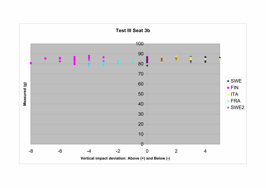
Test III Seat 3b
0
10
20
30
40
50
60
70
80
90
100
-8 -6 -4 -2 0 2 4Vertical impact deviation: Above (+) and Below (-)
Mea
sure
d (g
) SWEFINITAFRASWE2

IMPACT FROM SWING ELEMENTSRound Robin 2006
Test serie IV Type of seat Point of impact
Seat 3a Centre, Above and Below
Measu -red *)
Devia- tion **)
Measu -red *)
Devia- tion **)
Measu -red *)
Devia- tion **)
Measu -red *)
Devia- tion **)
Measu -red *)
Devia- tion **)
301 66,7 20 2+ 65,9 23 1- 64,1 22 0 61,3 23 1- 8 L 64,8 21 1+302 62,7 23 1- 68,2 22 0 65,7 22 0 61,6 22 0 10 L 63,3 22 0303 64,3 26 4- 66,1 22 0 59,9 27 5- 61,5 23 1- 11 L 49,2 24 2-304 64,1 26 4- 67,2 22 0 10 61,1 23 1- 61,9 23 1- 14 L 64,8 19 3+305 64,6 23 1- 68 22 0 10 65,1 20 2+ 61,7 20 2+ 6 R 61,1 23 1-306 65,7 22 0 65,3 21 1+ 63,4 21 1+ 58,9 23 1- 7 L 64,7 19 3+307 64,8 25 3- 64,8 20 2+ 64,1 20 2+ 58,7 22 0 14 L 62,2 23 1-
64,7 66,5 63,3 60,8 61,410 308 67,4 16 4- 66,9 12 0 66,8 12 0 59 10 2+ 27 R 66 11 1+
mm 309 70,8 10 2+ 68,7 12 0 10 66,8 12 0 62,1 13 1- 5 R 66,7 7 5+310 68,5 9 3+ 70,9 12 0 65,7 13 1- 61,7 11 1+ 28 L 65,6 12 0311 70,6 11 1+ 71,2 12 0 67,2 13 1- 62,3 10 2+ 7 L 64,8 11 1+312 68,7 12 0 68,6 12 0 66,2 14 2- 62,6 10 2+ 12 L 64,2 12 0313 66,0 13 1- 70,6 12 0 10 65,3 12 0 63,2 10 2+ 10 L 65,7 8 4+314 69,3 13 1- 72,3 12 0 70,7 11 1+ 63,3 11 1+ 13 L 64,4 10 2+
68,8 69,9 67,0 62,0 65,310 315 58,9 33 1- 62,6 31 1+ 57,9 32 0 57,5 30 3+ 5 R 60,3 32 0
mm 316 58,2 32 0 60,9 32 0 56,3 33 1- 56,7 32 0 8 L 58,6 33 1-317 61,6 31 1+ 61,7 31 1+ 56,6 33 1- 55,3 33 1- 2 L 59 32 0318 57,4 34 2- 60,6 30 2+ 55,3 33 1- 58,7 31 1+ 0 52,7 38 6-319 57,5 35 3- 61,2 30 2+ 55,4 32 0 54,8 34 2- 13 L 58,7 32 0320 57,3 33 1- 60,9 30 2+ 57,1 32 0 55,6 32 0 2 L 56,1 35 3-321 58,0 32 0 60,3 31 1+ 56,5 33 1- 53,2 33 1- 7 L 56,6 35 3-
58,4 61,2 56,4 56,0 57,4
*) Distance measured from the upper edge of the rubber**) Above + and - below
Above: 4,1 3,4 3,6 1,2 3,9Centr: 64,7 66,5 63,3 60,8 61,4Below: -6,3 -5,3 -6,9 -4,8 -4,0
Sweden IIMeasu-
red value
g
Point of impact, mm
Deviation from
horizontal line, mm
Centre
Above
Below
Type of swing
Single-seat
Deviation from
horizontal line, mm
Sweden Finland ItalyPoint of impact,
mmDeviation
from horizontal line, mm
Point of impact, mm
France
Measu- red value
g
Testno:
Measu- red
valueg
Measu- red value
g
Point of impact, mm
Deviation from
horizontal line, mm
Deviation from
horizontal line, mm
Measu- red value
g
Point of impact, mm
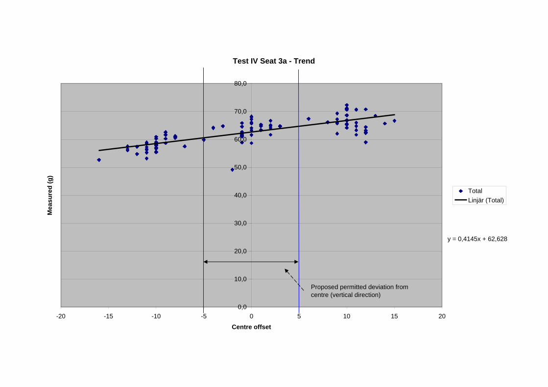
Test IV Seat 3a - Trend
y = 0,4145x + 62,628
0,0
10,0
20,0
30,0
40,0
50,0
60,0
70,0
80,0
-20 -15 -10 -5 0 5 10 15 20
Centre offset
Mea
sure
d (g
)
TotalLinjär (Total)
Proposed permitted deviation from centre (vertical direction)
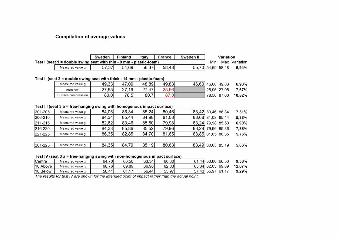
Compilation of average values
Sweden Finland Italy France Sweden IITest I (seat 1 = double swing seat with thin - 9 mm - plastic-foam) Min Max Variation
Measured value g 57,37 54,69 56,37 58,48 55,70 54,69 58,48 6,94%
Test lI (seat 2 = double swing seat with thick - 14 mm - plastic-foam)Measured value g 49,33 47,09 48,89 49,83 46,60 46,60 49,83 6,93%
Area cm2 27,95 27,19 27,47 25,96 25,96 27,95 7,67%Surface compression 80,0 78,5 80,7 87,0 78,50 87,00 10,82%
Test lll (seat 3 b = free-hanging swing with homogenous impact surface)201-205 Measured value g 84,06 86,34 85,24 80,46 83,42 80,46 86,34 7,31%206-210 Measured value g 84,34 85,44 84,98 81,08 83,68 81,08 85,44 5,38%211-215 Measured value g 82,62 83,46 85,50 79,98 83,24 79,98 85,50 6,90%216-220 Measured value g 84,38 85,86 85,52 79,96 83,28 79,96 85,86 7,38%221-225 Measured value g 86,35 82,85 84,70 81,65 83,85 81,65 86,35 5,76%
201-225 Measured value g 84,35 84,79 85,19 80,63 83,49 80,63 85,19 5,66%
Test lV (seat 3 a = free-hanging swing with non-homogenous impact surface)Centre Measured value g 64,70 66,50 63,34 60,80 61,44 60,80 66,50 9,38%10 Above Measured value g 68,76 69,89 66,96 62,03 65,34 62,03 69,89 12,67%10 Below Measured value g 58,41 61,17 56,44 55,97 57,43 55,97 61,17 9,29%The results for test lV are shown for the intended point of impact rather than the actual point
Variation