reprint from aluminium world 2009, volume 1 preserving … · · 2015-04-20reprint from aluminium...
TRANSCRIPT
Reprint from Aluminium World 2009, Volume 1
Preserving power quality for cost effective smelterpower consumption
Harmonic currents create electrical losses and if not compensated create costs for additional electrical power. The investment in a compensation system is repaid very quickly. ABB has the know-how and solutions.
Harmonic currents createelectrical losses and if not compensated create
additional electrical power costs.The cost of investing in a compen-sation system is repaid very quickly.By Max Wiestner, Industry ManagerPrimary Aluminium and ChristianWinter, Chief System EngineerRectiformers, ABB Switzerland andReto Schraner, Chief Commis-sioning Engineer, Sohar Aluminiumproject.
Electrical energy represents between30 to 40% of total aluminium productioncosts. Power quality is assessed by the“harmonic currents” still in the feedingpower grid after cleaning them up andthe “power factor” when the smelter isrunning under normal conditions. In thecase of a large two pot line smelter, atleast one additional power generationunit would be required if no power factorand harmonic current compensationsystem had been installed. The invest-ment cost for a compensation system,is far smaller than that required for an
Preserving Power Quality for Cost Effective Smelter PowerConsumptionABB Switzerland Ltd.
additional power generation unit and thecost of operating it.
Total Harmonic Distortion (THD)
THD is a measurable parameter that isused to evaluate power quality. The smelterAC/DC conversion system rectiformers,which convert the grid power (alternatingcurrent) to the DC power required by thepot rooms, create harmonic currents duethe nature of the more than 100-year-oldtechnology. These harmonic currents arecreated by the rectiformers when the DCcurrent is transformed and they appear ashigh frequency currents on top of thenormal current in figure 1.
These high frequency currents createelectrical losses within all consumingdevices if exposed to them. Low voltagemotors for example will use up to 10%more electrical power if the power quality isvery poor. With today’s smelters with up to1,200MW, this means that nearly oneadditional power generation unit will berequired just to compensate for poor powerquality, if not compensated by appropriateequipment.
Power Factor (PF)
PF is another measurable parameterused to evaluate power quality. Thepower factor is the difference between thepower, (active power) used to producealuminium and the power generated bythe power plant, (apparent power). Someequipment within the smelter consumes80% active power and creates 20% non-active (reactive) power. Naturally the ideais to have a very high power factor tominimise the power generation required.
Assuming a smelter requires 1,200MWand does not have any PF compensation,the power plant would require oneadditional generation unit just to producethe apparent power. Smelters thereforerequire systems that compensate for bothharmonic current distortion and powerfactor displacement.
Generation of harmonic currents
Rectiformers unfortunately createharmonic currents with different frequen-cies. Within smelters these currents arereduced by the use of 12-pulse rectifierunits which are designed in such a waythat the total rectiformer station will have a60-pulse displacement creating the leastpossible harmonic currents. When,however, a single pot line with a power
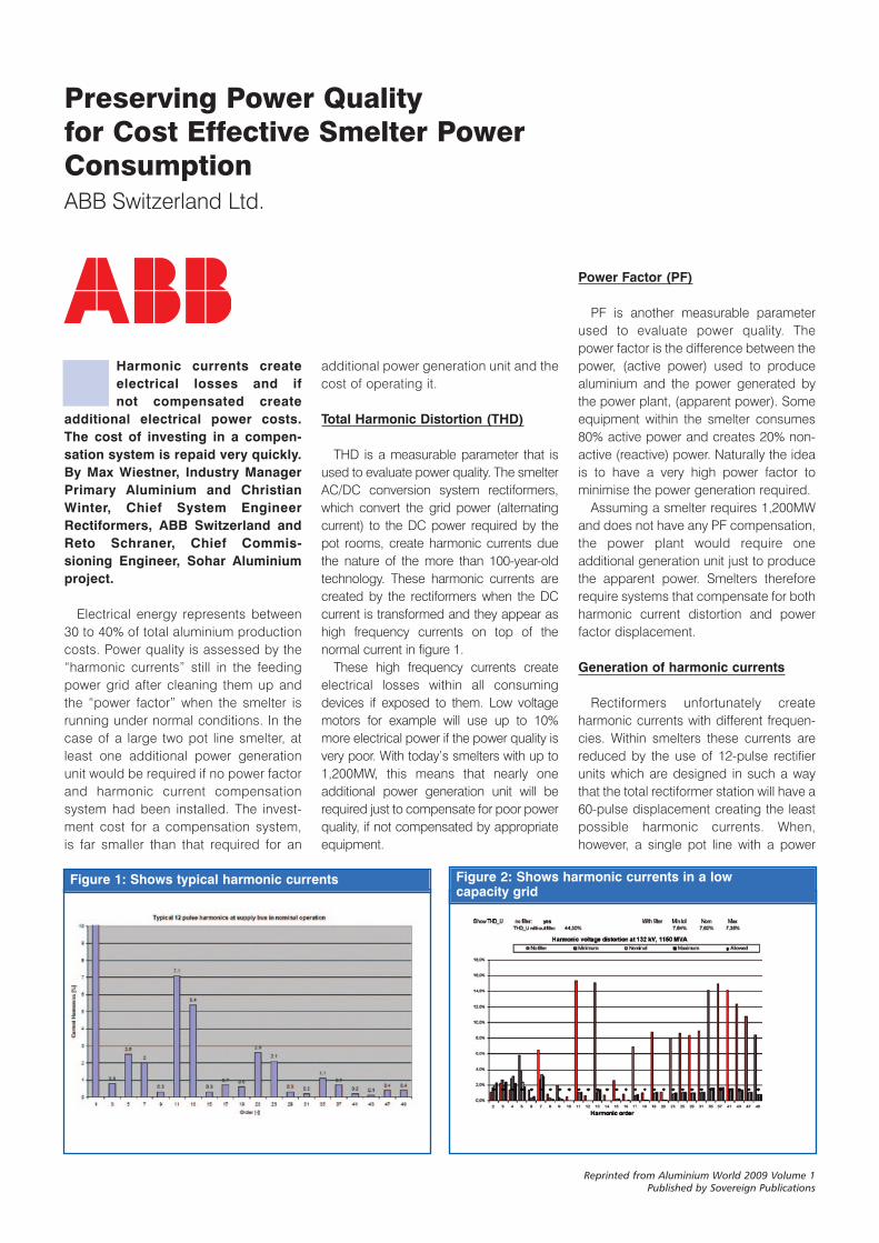
Figure 2: Shows harmonic currents in a low capacity grid
Figure 1: Shows typical harmonic currents
MIDDLE EAST FEATURE
Reprinted from Aluminium World 2009 Volume 1Published by Sovereign Publications
non-active power would be required. Thesmelter’s main power consumers (therectiformers) fortunately do not have aslow a power factor as typical motors butthey still require a large compensationsystem. At least 200-300MVA should becompensated per large pot line.
Combined THD and PF compensation
As it is not practical to have oneadditional generator unit producing theextra electrical power required due tonon-compensated harmonic currents andanother for power factor compensation,the obvious solution is to combine them.Typically such a system consists ofreactors and capacitors, which are alsoused to compensate the power factor,and resistors to damp the tuned circuitsto prevent resonances.
To compensate the majority ofharmonic currents these systems are splitup into two to five sub-systems tuned tocompensate different harmonic currents.The different tuning depends on thedesign of the rectiformer substation andthe feeding grid. Typical sub-systems,known as filter branches, are tuned to 3,5, 7, and 11 times the normal frequency.This is 50 or 60 hertz.
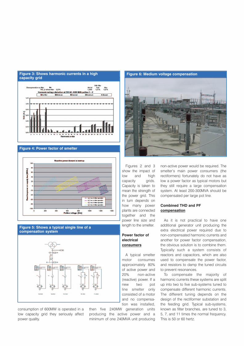
Figures 2 and 3show the impact oflow and highcapacity grids.Capacity is taken tomean the strength ofthe power grid. Thisin turn depends onhow many powerplants are connectedtogether and thepower line size andlength to the smelter.
Power factor ofelectricalconsumers
A typical smeltermotor consumesapproximately 80%of active power and20% non-active(reactive) power. If anew two pot line smelter onlyconsisted of a motorand no compensa-tion was installed,
then five 240MW generation unitsproducing the active power and aminimum of one 240MVA unit producing
consumption of 600MW is operated in alow capacity grid they seriously affectpower quality.
MIDDLE EAST FEATURE
Figure 3: Shows harmonic currents in a high capacity grid
Figure 4: Power factor of smelter
Figure 5: Shows a typical single line of a compensation system
Figure 6: Medium voltage compensation
existing harmonic currents from the utilitygrid. They are of a much simpler designand require a smaller footprint but theirfeeding switchgear needs to be rated towithstand high voltage surges duringswitching operation.
Design of high voltage systems needs tobe based on the power contract limitationso that they can also meet the power factorrequirements during initial start up. Theirperformance is more suitable for highergrid capacities as it is very costly to installmulti-branch filters at higher voltages
High voltage design considerations
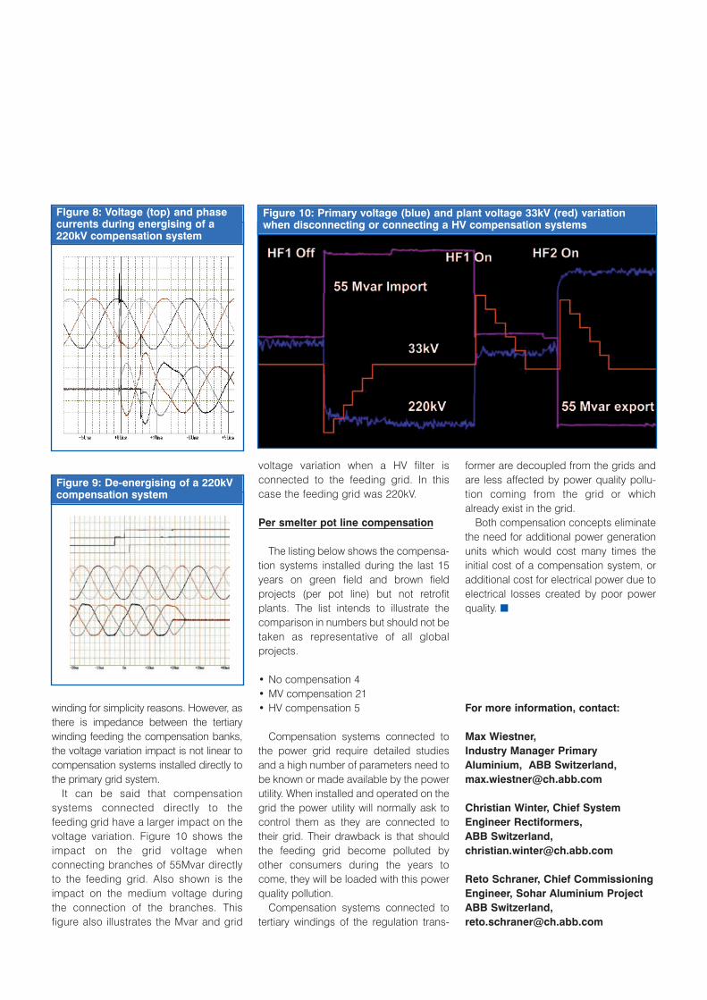
As these compensation systemsoperate at the utility level, high voltagesystems have a direct impact on the gridand vice versa. Energising and de-energising of such compensationsystems create a power quality distur-bance of their own. These systems havean affect similar to when a power line isenergised or de-energised and createvery high voltages that can destroycomponents or circuit breakers. Whenhigh voltage compensation systems arebeing considered, the feeding/controllingswitchgear needs to be capable ofoperating them. Figures 8 and 9 show theenergising and de-energising of a 220kVcompensation system with minimalpower quality distortion. This is due to theuse of ABB’s DCB/HPL 245kV circuitbreaker with a power frequency capableof withstanding a voltage of 460kV and the use of controlled switchingSwitchsync F236.
Voltage variation effect
When evaluating the two possiblecompensation system concepts, theimpact of the voltage variation at the highvoltage, as well as the smelter mediumvoltage, need to be considered. The tertiaryfilters (MV) have a lower but similar effecton the primary voltage rise, as the tapchangers within the regulation transformersare normally installed on the secondary
Latest designs are fitted with an MV circuitbreaker to allow incremental compensa-tion. With this solution each unit needs acompensation system capable of meetingperformance limits, even if only four unitsare in operation. With this design, highpower factors are also possible during theinitial smelter start up and harmoniccurrents do not reach the high voltagelevel. An additional advantage is that theycan be designed and installed without in-depth system studies of the feeding grid.This compensation system will not beimpacted, or only marginally, by the powerquality of the feeding grid.
High voltage (HV) compensation
High voltage (110-240kV) compensationsystems are connected to the utility powergrid via the high voltage switchgear. Thesecompensation systems require a more in-depth study to analyse their impact on thefeeding grid, in both directions, as thesystem will also possibly be loaded with
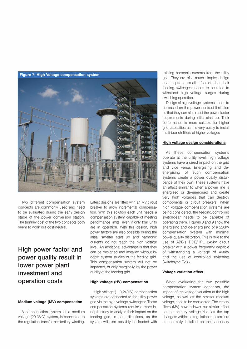
Two different compensation systemconcepts are commonly used and needto be evaluated during the early designstage of the power conversion station.The turnkey cost of the two concepts bothseem to work out cost neutral.
Medium voltage (MV) compensation
A compensation system for a mediumvoltage (20-36kV) system, is connected tothe regulation transformer tertiary winding.
MIDDLE EAST FEATURE
Figure 7: High Voltage compensation system
High power factor andpower quality result inlower power plantinvestment and operation costs
former are decoupled from the grids andare less affected by power quality pollu-tion coming from the grid or whichalready exist in the grid.
Both compensation concepts eliminatethe need for additional power generationunits which would cost many times theinitial cost of a compensation system, oradditional cost for electrical power due toelectrical losses created by poor powerquality. ■
For more information, contact:
Max Wiestner, Industry Manager PrimaryAluminium, ABB Switzerland,[email protected]
Christian Winter, Chief SystemEngineer Rectiformers, ABB Switzerland,[email protected]
Reto Schraner, Chief CommissioningEngineer, Sohar Aluminium ProjectABB Switzerland,[email protected]
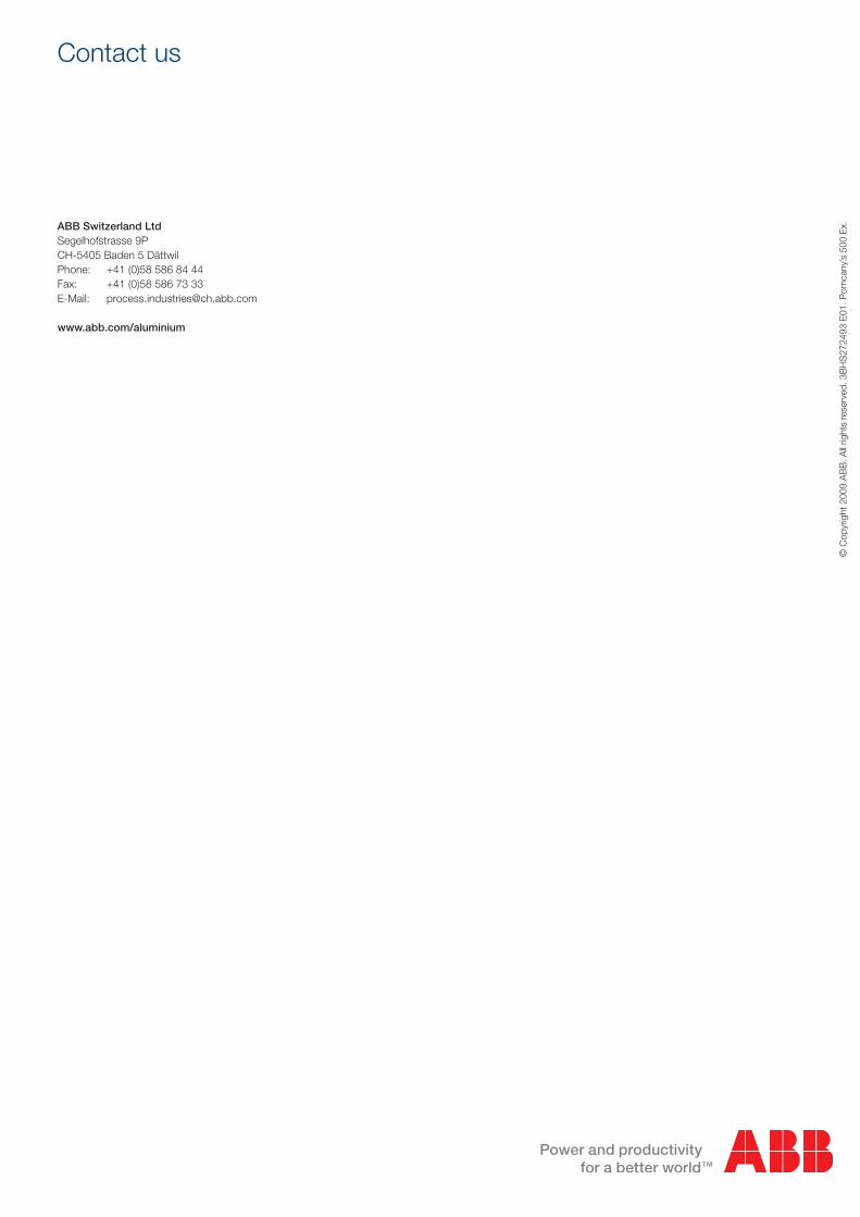
voltage variation when a HV filter isconnected to the feeding grid. In thiscase the feeding grid was 220kV.
Per smelter pot line compensation
The listing below shows the compensa-tion systems installed during the last 15years on green field and brown fieldprojects (per pot line) but not retrofitplants. The list intends to illustrate thecomparison in numbers but should not betaken as representative of all globalprojects.
• No compensation 4• MV compensation 21• HV compensation 5
Compensation systems connected tothe power grid require detailed studiesand a high number of parameters need tobe known or made available by the powerutility. When installed and operated on thegrid the power utility will normally ask tocontrol them as they are connected totheir grid. Their drawback is that shouldthe feeding grid become polluted byother consumers during the years tocome, they will be loaded with this powerquality pollution.
Compensation systems connected totertiary windings of the regulation trans-
winding for simplicity reasons. However, asthere is impedance between the tertiarywinding feeding the compensation banks,the voltage variation impact is not linear tocompensation systems installed directly tothe primary grid system.
It can be said that compensationsystems connected directly to thefeeding grid have a larger impact on thevoltage variation. Figure 10 shows theimpact on the grid voltage whenconnecting branches of 55Mvar directlyto the feeding grid. Also shown is theimpact on the medium voltage duringthe connection of the branches. Thisfigure also illustrates the Mvar and grid
MIDDLE EAST FEATURE
FIgure 8: Voltage (top) and phasecurrents during energising of a220kV compensation system
Figure 10: Primary voltage (blue) and plant voltage 33kV (red) variationwhen disconnecting or connecting a HV compensation systems
Figure 9: De-energising of a 220kVcompensation system
Contact us
ABB Switzerland LtdSegelhofstrasse 9PCH-5405 Baden 5 DättwilPhone: +41 (0)58 586 84 44Fax: +41 (0)58 586 73 33E-Mail: [email protected]
www.abb.com/aluminium
© C
opyr
ight
200
9 A
BB
. All
right
s re
serv
ed. 3
BH
S27
2493
E01
. Pom
cany
’s 5
00 E
x.