reproducing failure mode and life prediction of...
TRANSCRIPT

International Journal of Mechanical Engineering and Applications 2018; 6(1): 13-17
http://www.sciencepublishinggroup.com/j/ijmea
doi: 10.11648/j.ijmea.20180601.12
ISSN: 2330-023X (Print); ISSN: 2330-0248 (Online)
Reproducing Failure Mode and Life Prediction of Expansion Joint Using Field Data
Jung Soo Oh, Sueng Hyun Cho, Sung Jae Won, Dae Kyung Kang, Bong Soo Lee, Joong Sik Heo
Machine & Mensuration Division, Korea Testing Certification, Gun-po city, South Korea
Email address:
To cite this article: Jung Soo Oh, Sueng Hyun Cho, Sung Jae Won, Dae Kyung Kang, Bong Soo Lee, Joong Sik Heo. Reproducing Failure Mode and Life
Prediction of Expansion Joint Using Field Data. International Journal of Mechanical Engineering and Applications.
Vol. 6, No. 1, 2018, pp. 13-17. doi: 10.11648/j.ijmea.20180601.12
Received: February 12, 2018; Accepted: April 16, 2018; Published: April 27, 2018
Abstract: In this study, among plant equipment, valve and piping fitting which is vulnerable to waterhammer was selected
for diagnosis. Impulsive vibration by waterhammer was measured and applied to HIL simulator as operation data using HILS
method for reproducing failure mode and life prediction of them. For effective measuring vibration, accelerometer was adapted
for in the poor surroundings. Measurement results shows max. peak-to-peak vibration displacement was 21.40 mm caused by
waterhammer on the valve etc., which could affect structure stability of plant equipment. After that, using the acquired data, the
vibration durability of the expansion joint was tested. Meanwhile, in the case of vibration durability, internal pressure in the
expansion joint was proposed as main stress factor of durability life, life prediction model was induced by curve fitting along
with the datum at each pressure and verified. Thus, a further study will develop mixed life prediction model which will contain
another stress factor such as temperature.
Keywords: Expansion Joint, Failure Mode Reproducing, HILS, Life Prediction, Plant Equipment, Waterhammer
1. Introduction
In the case of safety diagnosis of plant equipment at
present, collecting data in the field are analyzed and stored as
DB for maintenance and replacement.
Also, most commercial plant equipment products is
examined and tested by domestic and international test
standards such as KS, ISO, ANSI/ASME. [1-3]
Nevertheless, It is difficult to predict the actual life of
product since product performance depends on actual
operating environment and conditions. Especially, under a
excessive condition such as waterhammer, the product is
vulnerable to breakage easily. So, it is not possible to predict
the actual life exactly.
Recently, using HILS (hardware-in-the-loop simulation)
method has been adopted for improving reliability and has
been extended throughout all industries because HILS is very
powerful reliability method which is reflecting actual
operation condition. But, safety assessment of plant field has
not reported yet. [4, 5]
HILS is one of the techniques for life assessment as
applying to repeating the specific conditions on a object until
it fails or failure. Therefore, attempt to introduce HILS in the
safety assessment of plant equipment would be effective.
For repeated application of a certain condition, some of
operating datum were measured, which of them was applied
to operating data of HIL simulator.
Also, in the case of reproducing failure, Among the plant
equipment, the expansion joint was selected and tested.
Reproducing failure mode was carried out according to each
conditions and then, using the results of each failure cycle, life
prediction model was induced and verified in this study.
(a) High temperature and high vibration
14 Jung Soo Oh et al.: Reproducing Failure Mode and Life Prediction of Expansion Joint Using Field Data
(b) high humidity and low temperature
Figure 1. Examples of diagnosis environment.
2. Selection of Environment and Object
Diagnosis
2.1. Selecting Sensor for Diagnosis
Waterhammer can damage to pump, valve and expansion
joint by feeding and stopping transfer fluid abruptly in
pipeline. [6]
In order to reduce excessive impact, a safety equipment
such as air-chamber has been adopted these days. But, It is
not easy to applied for aged plant environment considering
installation space and high cost. Therefore, lots equipment
are need to repaired and replaced in many places up until
now. Accordingly, valve etc. with high probability of being
exposed to waterhammer were selected in this study.
Some studies report the causes of transient response and
damage in piping systems on using accelerometer when
measuring vibration. [7-9]
In the case of application of non-contact displacement
sensor, which has narrow measurement range and need
additional jig for installation despite of high resolution. Also
removal coating layer and surfacing procedure are required to
surface of piping and equipment.
Laser measurement for displacement has high resolution
with sub-micron level but, is vulnerable to temperature,
humidity, wind and base excitation. So that is not suitable to
unstable environment in Figure 1 [10]
Therefore, In this study, accelerometer was selected for
vibration considering comprehensive conditions and
vibration displacement was induced by integrated initial
value twice.
Figure 2. Setup for waterhammer in the power plant pipeline.
Table 1. Specification of accelerometers.
Specification 333B30 333B40
Sensitivity (mV/g) 100 500
Measurement Range (g) ± 50 ± 10
Temperature Range (℃) -18 ~ 66
Frequency Range (Hz) 0.5 ~ 3,000
Resonant Frequency (Hz) > 3,000
Non-Linearity (%) < 1
Sensing Element Ceramic
Note g = m/s2
2.2. Data Measurement
Figure 2 indicates the setup for measuring vibration on the
valve by waterhammer. Diagnosis object is 6 inch glove
valve which is made of A216-WCB. Working fluid is high-
temperature water, design pressure is 50 kgf/cm2
design, temperature is up to 250°C. And this valve is connected and
supported to pipe by welding.
Major failure mode became known as crack on valve body
and disk breakage of valve
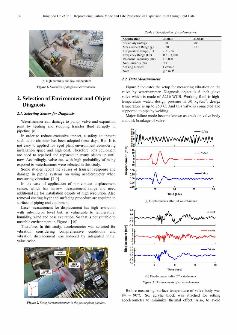
(a) Displacements after 1st waterhammer
(b) Displacements after 2nd waterhamme
Figure 3. Displacements after waterhammer.
Before measuring, surface temperature of valve body was
84 ~ 90°C. So, acrylic block was attached for setting
accelerometer to minimize thermal effect. Also, to avoid

International Journal of Mechanical Engineering and Applications 2018; 6(1): 13-17 15
amplification of measured value, placing at a position from
surface of pipe with 30 mm above. At that time, temperature
of sensing part(acrylic block ) was 40 ~ 42°C and lie at
operating range of Table. 1 and accelerometers were set
along with 3-axis direction.
Figure 3 is the edited results which are pre and post section
during 60- sec measurement period.
Displacements of Figure 3 (a) is the results 1st
waterhammer which are measured about 51-sec from Initial
measurement point. and displacements of Figure 3 (b) is the
results 2nd
waterhammer are measured about 7-sec from
re-measurement point.
In the results of Figure 3 (a), there are two times impacts
in the direction of the Y-axis. Max. peak to peak (p-p) of
displacement was 21.40 mm level, p-p value of displacement
was 0.68 mm level in the direction of the Z-axis. Also, p-p
value of displacement was 3.90 mm level in the direction of
the Y-axis and 1.7 mm level in the direction of the Z-axis in
the Figure 3 (b)
Considering results of each direction, displacements of X
and Z-axis had smaller than Y-axis. This would be affected
by connection structure with X and Z-axis direction
2.3. HIL Simulator
Figure 4. HIL simulator for vibration reproducing.
Figure 5. Comparison between measured data and operating data.
Figure 4 shows HIL simulator for vibration reproducing.
This simulator can carry out multi-axis and has displacement
& load control as well. Also, software for HIL simulator can
operate random wave and monitor number of reproducing.
Abnormal signal from a sensor(e.g. pressure) which was
attached to can be detected for failure mode.
For verification of the vibration reproduction, Y-axis data
of Figure 3 (b) was applied as operation data and compared
in the Figure 5. At that time, following error was 0.01 mm
level. Hence, it is possible to reproduce displacement with
mm level.
3. Failure Mode Reproduction
3.1. Test Setup
In this study, vibration durability tests were constructed as
shown in Figure 6 to reproduce failure mode of expansion
joint using measured data at section 2. The specimen is
bellows type expansion joint (150A).
Expansion joint usually is used for preparation such as
excessive thermal deformation, shock by waterhmmer in the
plant system widely.
Design pressure of expansion joint is 20 kgf/cm2,
expansion length is ± 15 mm. and material of flange and
bellows is SS400 and STS 304 respectively. Also expansion
joint is consist of bellows and sleeve with 0.6t by welding
Major failure mode of expansion joint are leakage by crack,
deformation and breakage of connection to pipe by shock.
Test setup is consist of hydraulic actuator system (Max.
100 kN) and software for control and monitoring. Expansion
joint was connected to actuator, water pressure tester is set
for supplying water and adjusting pressure and air-chamber
for maintaining initial setting pressure. Lastly, pressure
transmitter was attached for monitoring real-time pressure
state.

16 Jung Soo Oh et al.: Reproducing Failure Mode and Life Prediction of Expansion Joint Using Field Data
Figure 6. Set-up for durability test of expansion joint for failure reproducing.
Figure 7. Operating data applied to HIL Simulator for vibration
reproducing.
3.2. Test Scheme
The main causes of failure of the expansion joint are
sudden internal pressure change, thermal change of working
fluid and breakage by external impact. In this study, external
impulse was applied for vibration durability of expansion at
first.
In addition, this study suppose that internal pressure of
expansion joint is the major stress factor in durability life.
Test conditions is shown in Table 2., Test was finished
when leakage was occurred during the test.
Table 2. Test condition according to internal pressure of expansion joint.
Case Pressure (kgf/cm2) Q'ty of Specimen
I 10 3
II 11 3
III 13 3
3.3. Test Results
Results at each internal pressure are presented in Table 3.
In the case of 10 kgf/cm2, average life up to failure was 2,700
cycle. Also, In the case of 11 kgf/cm2 and 13 kgf/cm
2, average
life was 1,800 cycle and 1,000 cycle individually.
On the other hand, the life deviation was inclined to
increased as internal pressure was lower. This phenomenon
was estimated that deformation and expansion of bellows
part was proceeded slowly at lower pressure.
Failure mode during the test was shown in Figure 8
Table 3. Test results for each condition (cycle).
Pressure (kgf/cm2) Specimen Life (cycle) Average Life
(cycle)
10
#1 2,403
2,733 #2 2,589
#3 3,208
11
#1 2,025
1,814 #2 1,890
#3 1,528
13
#1 1,138
1,073 #2 1,257
#3 824
(a) Deformation
(b) Crack on surface of bellows part
(c) Leakage during durability test
Figure 8. Failure mode.
4. Development of life Prediction Model
4.1. Life Prediction Model
Assuming that life of the expansion joint follow inverse
power model which is suitable to mechanical components.

International Journal of Mechanical Engineering and Applications 2018; 6(1): 13-17 17
Then, life model equation is proposed as (1) below.
� � �����
�� � � (1)
Where,
� = Prediction life (cycle)
�� = Constant of inverse power model
�in = Stress factor (inner pressure)
S = Stress index
C = Constant
Figure 9. Curve fitting for datum at each pressure.
In order to derive coefficients of equation, the test results
at each pressure were illustrated as Figure 10 and then, a
curve was inserted along with the results for finding tendency
of datum. After that, the each coefficient was induced that ��,
S and C was 845,907.9, 1.651 and 750.8 at each.
4.2. Verification of Life Prediction Model
For verification of life prediction model in this study,
vibration durability tests at 7 kgf/cm2
was performed as
shown in Table 4.
It turned out that average life was 12,400 cycle, It was
close to estimated value, 12,946 cycle by life prediction
model within deviation range comparatively.
Table 4. Test results at 7 kgf/cm2.
Pressure (kgf/cm2) Specimen Life (cycle) Average Life
(cycle)
7
#1 15,128
12,420 #2 11,229
#2 10,904
5. Conclusion
In this study, plant equipment which is vulnerable to
waterhammer was made diagnosis and predicted life of
expansion joint by reproducing failure mode.
Using an accelerometer that is relatively easy to install,
displacement vibration by waterhammer was measured and
applied to vibration durability tests.
Also, internal pressure of expansion joint is the major
factor in durability life was assumed, verified and life
prediction model was induced in this study.
However, the life prediction model in this study has
limitation on specific surroundings and operating condition.
Hereby, in addition to pressure, temperature will be
considered as stress factor, mixed life prediction model will
be developed in the future.
Acknowledgments
This research was supported by a grant (No.
18IFIP-B089065-05 & No. 16CTAP-C117188-01) from
Technology Advancement Research Program funded by
Ministry of Land, Infrastructure and Transport of Korean
government.
References
[1] "KS B 4500: Expansion Joints", Korea Standard Association, 2016.
[2] “ISO 15348(en): Pipework-Metal bellows expansion joints", International Organization for Standardization, 2002.
[3] "ASME B31.3: Processing Piping", The American Society of Mechanical Engineers", 2016.
[4] S. Olma, A. Kohlstedt, P. Traphoner, K. P. Jaker, A. Trachtler, “Substructuring and Control Strategies for Hardware-in-the-Loop Simulations of Multiaxial Suspension Test Rigs”, the Journal of International Federation of Automation Control, Vol. 49, Issue 21, pp. 141-148, 2016R. Nicole, “Title of paper with only first word capitalized,” J. Name Stand. Abbrev.
[5] K. Y. Jeong, R. C. Kang, H. C. Lee, "Prediction of Iron Loss Resistance by Using HILS System", The Korean Society Of Automotive Engineers, Transaction of the Korean Society of Automotive Engineers, Vol. 23, No. 1, pp25-33, 2015M. Young, The Technical Writer's Handbook. Mill Valley, CA: University Science, 198.
[6] J. H. Lee, H. H. Lee, B. H. Kyoung, J. W. Woo, K. H. Lee, " A Study of Water-Hammer Control with Statuette-Piping", The Korean Society for Noise and Vibration Engineering, Annual Spring Conference, pp. 674-678, 2007.
[7] J. S. Suh, "A Study on the Measurement of the Pipeline Displacement Using Accelerometers", The Korean Society for Noise and Vibration Engineering, Vol. 24, No. 6, pp. 476-482, 2016.
[8] Y. H. Kim, "Examination on High Vibration and Branch Vent Pipe's Failure of Complex Piping System Suppling Condensate-water in Power Site", The Korean Society for Noise and Vibration Engineering, Annual Autumn Conference, pp. 380~384. 2010.
[9] Y. C. Bae, Y. S. Lee and Y. H. Kim, "Countermeasure on High Vibration of Branch Pipe with Pressure Pulsation Transmitted from Main Steam Header, Transactions", The Korean Society for Noise and Vibration Engineering", Vol. 15, No. 8, pp. 988~995, 2005.
[10] Hewlett Packard Co., “Laser Measurement System User’s Guide, Manual Part No. 00528-90010,” 1984.