request for proposal for design, development and delivery ......3 development of prototype model 3.1...
TRANSCRIPT

P a g e | 1
Request
For
Proposal
For
Design, Development and Delivery of the
Antenna Controller
Space Applications Center
Ahmedabad, Gujarat

P a g e | 2
This document contains proprietary information of SAC/ISRO, Ahmadabad.
Unauthorized copy or reproduction of this document in whole or in part without the
prior written consent of SAC/ISRO is strictly forbidden.
SAC/ISRO reserves the right to alter this information at any time without notice.
Abbreviations/Definitions:
RFP Request for Proposal
SAC Space Applications Centre
ISRO Indian Space Research Organization
Purchaser Space Applications Centre
Bidder The Firm which is participating in Bid
Vendor The Firm on whom order is placed
GUI Graphical User Interface

P a g e | 3
Table of Contents 1.0 Introduction ...............................................................................................................5 2.0 Basic Block Diagram of the Controller Electronics ......................................................5
2.1 Basic Description of Controller Circuit ..............................................................6 2.2 Concept of Active Addressing .............................................................................7
3.0 Scope of Work ...........................................................................................................8 4.0 Major specifications of the Controller Circuit ..........................................................9 5.0 List of deliverables by SAC ISRO to Vendor .........................................................10 6.0 List of deliverables by Vendor to SAC ISRO .........................................................10 7.0 Delivery Schedule ...................................................................................................10
8.0 Functionality Test ....................................................................................................10 9.0 Guidelines to Vendor ............................................................................................... 11 10.0 Other Terms and Conditions ...................................................................................... 11
P a g e | 4
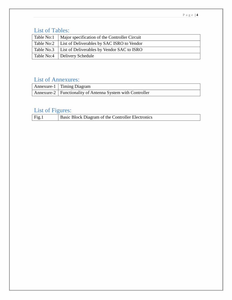
List of Tables: Table No:1 Major specification of the Controller Circuit
Table No:2 List of Deliverables by SAC ISRO to Vendor
Table No.3 List of Deliverables by Vendor SAC to ISRO
Table No:4 Delivery Schedule
List of Annexures: Annexure-1 Timing Diagram
Annexure-2 Functionality of Antenna System with Controller
List of Figures: Fig.1 Basic Block Diagram of the Controller Electronics
P a g e | 5
1.0 Introduction
Space Application Center (SAC) is responsible for the design, development and
characterization of the Antenna Systems for space and ground segments.
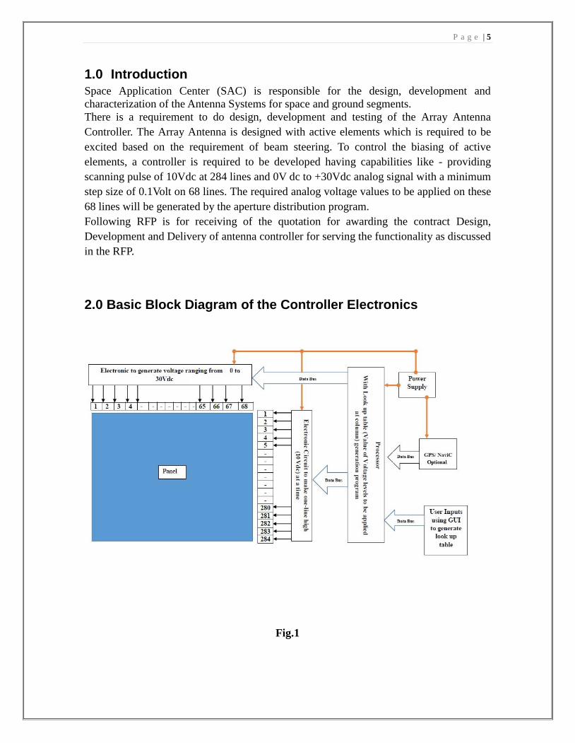
There is a requirement to do design, development and testing of the Array Antenna
Controller. The Array Antenna is designed with active elements which is required to be
excited based on the requirement of beam steering. To control the biasing of active
elements, a controller is required to be developed having capabilities like - providing
scanning pulse of 10Vdc at 284 lines and 0V dc to +30Vdc analog signal with a minimum
step size of 0.1Volt on 68 lines. The required analog voltage values to be applied on these
68 lines will be generated by the aperture distribution program.
Following RFP is for receiving of the quotation for awarding the contract Design,
Development and Delivery of antenna controller for serving the functionality as discussed
in the RFP.
2.0 Basic Block Diagram of the Controller Electronics
Fig.1

P a g e | 6
2.1 Basic Description of Controller Circuit
All the points described below about the required antenna controller are to make
understanding about the requirement and functionality of developed controller. Vendor to
comply all the points.
Sr.No. Description Compliance(Y/N)
1 Panel Matrix: These are the elements that has to be biased.
This will have a terminal of 284 for Gate Lines and 68 for
Drain Lines available at the panel to be interfaced with the
Controller.
2 Program Controller: It can be a microcontroller/FPGA or
other controller that can be programmed for the controlling of
active circuit with required logics and external inputs.
3 Gate Driving Circuit: This circuit need to generate 10 Vdc
pulse to bias the gate line in scanning mode
4 Timing Synchronization Circuit: This will make
synchronization of the Gate and Drain Lines; the gate line
should first receive the pulse and then the voltage for the
corresponding lines will be applied to the drain lines by drain
driving circuit.
Timing Diagram has been attached at per annexure-1
5 GPS/NaviC: it will provide the current location of the panel
site; this data will be used by the processor to calculate the
look up table for the user defined satellite position.(Optional)
6 Gyros: it will provide the data related to any deviation in
pitch/yaw/roll. This will be taken care in to the calculation of
the look up table by the processor.(Optional)
7 Power Drive: Power drive will be powered by 230V/50Hz
1-phase power supply.
8 LAN & Bluetooth: Port to communicate with the processor.
9 User Input: User Input will be the name of satellite, for which
processor will have the location in its memory. And
Computation table comprising the required voltage levels will
generated for the required satellite.
P a g e | 7
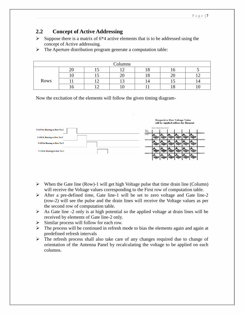
2.2 Concept of Active Addressing
Suppose there is a matrix of 6*4 active elements that is to be addressed using the
concept of Active addressing.
The Aperture distribution program generate a computation table:
Now the excitation of the elements will follow the given timing diagram-
When the Gate line (Row)-1 will get high Voltage pulse that time drain line (Column)
will receive the Voltage values corresponding to the First row of computation table.
After a pre-defined time, Gate line-1 will be set to zero voltage and Gate line-2
(row-2) will see the pulse and the drain lines will receive the Voltage values as per
the second row of computation table.
As Gate line -2 only is at high potential so the applied voltage at drain lines will be
received by elements of Gate line-2 only.
Similar process will follow for each row.
The process will be continued in refresh mode to bias the elements again and again at
predefined refresh intervals
The refresh process shall also take care of any changes required due to change of
orientation of the Antenna Panel by recalculating the voltage to be applied on each
columns.
Columns
Rows
20 15 12 18 16 5
10 15 20 18 20 12
11 12 13 14 15 14
16 12 10 11 18 10

P a g e | 8
3.0 Scope of Work
Vendor shall fill the compliance table wherever applicable-
Sr.No. Description Compliance
(Y/N)
1 SAC Team will provide MATLAB code for generating the
computation matrix, vendor to convert it in to the required
format/language.
2 Basic functioning of the Controller has been shown in the
Annexure no:2.
3 Development of Prototype model
3.1 A Prototype model is to be developed in Phase-1 development as
per the details given below. Thereafter, Phase-2 development
shall be done for final product.
Details for Prototype (Phase-1) development
I. Number of Gate Lines - 32.
II. Number of Drain Lines - 32.
III. Gate Scan cycle of 10Vdc.
IV. Analog drain voltage ranging from 0Vdc to 30Vdc with a
minimum step size of 0.1Volt.
V. Scan cycle for Gate – 9.6mSec to 19.23mSec.
VI. Gate Pulse width- 300µSec to 600µSec
3.2 Gate Pulse width should be programmable (Ranging from
300µSec to 600µSec)
4 After successful demonstration of the prototype model of the
controller, Vendor to start the development of the final product.
Specification of the final product has been described in table
No:1 (where is table no. Add nos. to all the tables)
5 Developed Controller is to be housed below the Antenna panel of
size 0.8m*0.8m and can have a maximum form factor of 30cm x
30 cm x 12cm (LxWxH). If there is any change in the form
factor, Vendor has to consult with the SAC Focal Person.
6 The maximum current that can be drawn by the interfaced
Antenna panel is 1.5 Amp.
7 It is required to have 8 spare IOs for Drain and Gate lines each.
Vendor to note after considering the spare IOs, The controller
need to control (284+8) x (68+8) IOs.
8 Vendor to provide the feasibility to interface with the GPS/NaviC
and Gyros with the controller.
Provision of usability of component by GUI should be there i.e.
User can decide whether to use the live GPS and Gyros or not.
9 Vendor to provide separate quotation for single unit of GPS and
Gyro.
10 The type of connector to interface the controller with the Antenna
can be FFC or FPC type that can be decided after the mutual
agreement with SAC Team.
P a g e | 9
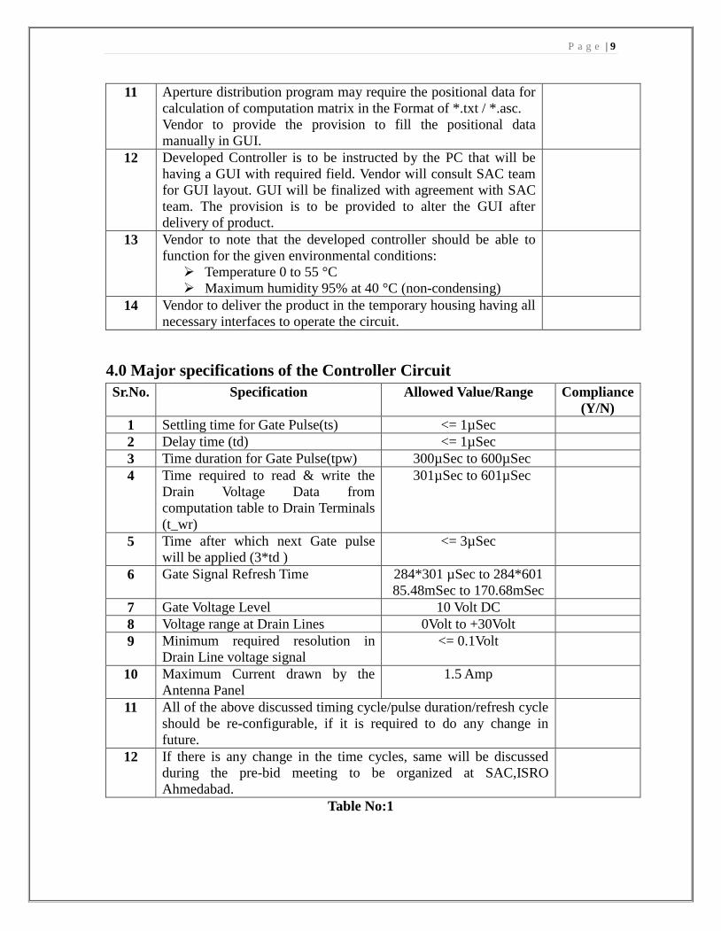
11 Aperture distribution program may require the positional data for
calculation of computation matrix in the Format of *.txt / *.asc.
Vendor to provide the provision to fill the positional data
manually in GUI.
12 Developed Controller is to be instructed by the PC that will be
having a GUI with required field. Vendor will consult SAC team
for GUI layout. GUI will be finalized with agreement with SAC
team. The provision is to be provided to alter the GUI after
delivery of product.
13 Vendor to note that the developed controller should be able to
function for the given environmental conditions:
Temperature 0 to 55 °C
Maximum humidity 95% at 40 °C (non-condensing)
14 Vendor to deliver the product in the temporary housing having all
necessary interfaces to operate the circuit.
4.0 Major specifications of the Controller Circuit
Sr.No. Specification Allowed Value/Range Compliance
(Y/N)
1 Settling time for Gate Pulse(ts) <= 1µSec
2 Delay time (td) <= 1µSec
3 Time duration for Gate Pulse(tpw) 300µSec to 600µSec
4 Time required to read & write the
Drain Voltage Data from
computation table to Drain Terminals
(t_wr)
301µSec to 601µSec
5 Time after which next Gate pulse
will be applied (3*td )
<= 3µSec
6 Gate Signal Refresh Time 284*301 µSec to 284*601
85.48mSec to 170.68mSec
7 Gate Voltage Level 10 Volt DC
8 Voltage range at Drain Lines 0Volt to +30Volt
9 Minimum required resolution in
Drain Line voltage signal
<= 0.1Volt
10 Maximum Current drawn by the
Antenna Panel
1.5 Amp
11 All of the above discussed timing cycle/pulse duration/refresh cycle
should be re-configurable, if it is required to do any change in
future.
12 If there is any change in the time cycles, same will be discussed
during the pre-bid meeting to be organized at SAC,ISRO
Ahmedabad.
Table No:1

P a g e | 10
5.0 List of deliverables by SAC ISRO to Vendor
Sr.No. Items/Equipment/others Qty. Compliance
(Y/N)
1 MATLAB Code of the Aperture
Distribution Program
1
Table No:2
6.0 List of deliverables by Vendor to SAC ISRO
Sr.No. Items/Equipment Qty. Compliance
(Y/N)
1 Prototype Controller 1
2 Antenna Controller 1
3 Source Code of the Programs being used As per applicable
4 Test Reports and Data sheets of all the
individual components
As per applicable
5 Vendor has to submit detailed testing
reports of prototype and final product
1
Table No:3
7.0 Delivery Schedule
Sr.No. Items/Equipment Time Period
[T0 – Date of acceptance of
PO]
Compliance
(Y/N)
1 Prototype Controller T0+6 Months
2 Antenna Controller T0+12 Months
Table No:4
8.0 Functionality Test
Sr.No. Description Compliance
(Y/N)
1 At initial stage the Prototype Controller will be verified at the
Purchaser Premises for selectable range of voltage levels, scan
cycle, interval and methodology of the scanning to be opted
during the final product.
This can be verified by using oscilloscope or other test
equipment.
2 Vendor should note that if the prototype model is not
functioning satisfactorily, it is required to correct and
demonstrate it again at no cost.
3 After Satisfactory performance of the Prototype model, Vendor
will be informed for the development of the final product.
4 The final product delivered to SAC will be tested for
different-different sets of instruction to verify the timing cycles

P a g e | 11
and voltage levels.
Performance will be compared with the simulated results
performed by SAC Team.
9.0 Guidelines to Vendor
10.0 Other Terms and Conditions 1. Acceptance Criteria: Developed Antenna Controller will be validated at SAC
using various methods to check the required voltage levels and the timing of the
scan cycle as per the requirements.
2. Rework: Rework will be free of charge.
3. Rejection: Vendor has to take utmost care and bear the cost of material, if
rejected.
4. Confidentiality: Vendor shall not divulge the information relating to the circuits,
products, fabrication procedures, quality control methods etc., that are not in
public domain and exclusively provided by ISRO for ISRO’s own requirements,
to any third party and shall not use for Vendor’s own commercial purpose,
without prior written consent from ISRO. However, Vendor is free to use such
methods / procedures for works assigned by any of the Centers / Units of ISRO /
DOS.
5. Secrecy: The technical information, drawings, specifications and other related
documents, forming part of the Contract, are the property of SAC and shall not be
Sr.No. Description Compliance
(Y/N)
1 Vendors to attend the pre-bid meeting to be arranged by the SAC
Purchase at SAC ISRO Premises.
Vendors can ask any technical queries in this meeting.
2 Vendor to provide point to point compliance for all the points.
3 Vendor to quote the price of the discrete components that can be
procured as spare for replacement of faulty component in future.
4 One of the focal person of SAC will participate in the
development for the proper execution of the work
5 Any details/input that is needed to incorporate in the
programmable controller will be shared to the vendor for
Example- List of satellite and their location that is required to
program the controller.
6 Vendor has to provide Warranty of at least one year for all the
deliverable.
7 After development of the final Controller, Product has to be
delivered to SAC Ahmedabad.

P a g e | 12
used for any other purpose, except for the execution of the Contract. All rights,
including rights in the event of grant of patent and registration of design are
reserved. The technical information, drawings, specifications, records and other
documents shall not be copied, transcribed, traced or reproduced in any other form
or otherwise in whole and/or duplicated, modified, divulged and/or disclosed to a
third party nor misused in any other form whatsoever without SAC’s consent in
writing except to the extent required for the execution of this Contract. These
technical information, drawings, specifications and other related documents shall
be returned to SAC with all approved copies and duplicates, if any, immediately
after they have been used for the agreed purpose.
6. Publicity: No publicity of any kind whatsoever regarding this contract shall be
given by the vendor without prior permission of SAC.
7. Non-disclosure Agreement: The Vendor shall maintain absolute secrecy and
security to the development of Antenna Controller and methods, documentation
etc., provided by SAC for the purpose of Antenna Controller development. The
Vendor shall return the original and copies of the same to SAC after completion
of the work. The technical information / papers / drawings / standards to be
provided by SAC from time to time, are for the execution of this Contract only;
and should not be used / copied / reproduced / published in any form by the
Vendor or his personnel.
8. Service Provider & Personnel deputed by the Vendor shall maintain absolute
secrecy and security of the circuit schematics, drawings, process methods /
documentation etc., provided by SAC for the purpose of design, fabrication and
testing or stored on various computing systems at SAC. Vendor shall return the
original and copies of the same to SAC after completion of the work. The
technical information / papers / drawings to be provided by SAC from time to
time, are for the execution of this Contract only; and should not be used / copied /
reproduced / published in any form or disclosed to third party, by the Vendor or
his personnel. Thus, the Vendor is required to sign a Non-Disclosure Agreement
(NDA) with SAC. Vendor will also be responsible for any violation or
infringement of NDA by his personnel.
9. The vendor has to follow top quality standards during the completion of the whole
project. SAC may depute their personnel/ representatives if required to the work
site, wherever it may be required. The vendor may coordinate for the visit of
SAC’s team.

P a g e | 13
Annexure-1
Timing Diagram
Sr.No. Description
1 ts Settling Time for Gate Pulse
2 tpw Gate Pulse width
3 t_wr Time needed to write the drain data
4 td Time delay for Gate pulse after writing the Drain Data
5 t_refresh Refreshing time

P a g e | 14
Annexure:2
Functionality of The Antenna System with Controller