requirements and a case-study for sle from … · requirements and a case-study for sle from...
TRANSCRIPT
Requirements and a Case-Study for SLE from Robotics:Event-oriented Incremental Component Construction
Ingo Lutkebohle and Sven WachsmuthApplied Informatics Group
Bielefeld University{iluetkeb,swachsmu}@techfak.uni-bielefeld.de
Abstract: Research in the area of human-robot interaction requires a tight interleav-ing of incremental system development and experimentation across different roboticplatforms. In terms of software engineering this proposes certain challenges to systemdevelopment that are only partially covered by component-based robotic engineering.For the incremental component composition, we introduce an explicit ganularity levelabove functions but below components using an event-driven data-flow model. Twodifferent case studies show its impact on the re-use and maintenance of software com-ponents. We discuss requirements and possible impact of software languages for thegraph-based decomposition approach.
1 Introduction
Robotics is a sub-area of cyber-physical systems that is highly diverse, internally,with hardware ranging from nano-scale robots through robots acting in human envi-ronments to industrial and field robots. The software eco-system in robotics is at leastas diverse – if not more. Correspondingly, platform independence and re-use acrossplatforms and software frameworks is of high importance in this area. Moreover, re-search systems in robotics – especially in the area of human-robot interaction – arechanging rapidly, in order to explore and test novel ideas. Although, re-use is an en-abling key factor, software components practically need significant adaptation beforebeing applied on a new or changed system environment. We believe that languageengineering can contribute here, by making re-use more efficient.
Our foundation is the component-based software architecture approach, which isnow the dominant mode for building large robot software systems. In the last years,different component models and operating cores have been put forward in this regard,like OROCOS [BsK03], SmartSoft [Sch07], CLARAty [Nes07], and ROS [QCG+09].These address how to compose a system from components, but they say little aboutthe creation of the components themselves. As in many other areas, components areusually created from both new and existing code. The writing of the necessary compo-sition code is usually done in the same language as the combined code, which is oftenC/C++ or a similar language. The effort for composing and changing such componentsis typically underestimated, especially if functionality is not already isolated into a li-brary. In this case, it can be even difficult to extract the functionality for re-use in newcomponents. In order to address these challenges, the development model needs toexplicitly support fast changes or re-use. Rapid component construction should makethis easier, and in robotics, it can take advantage of the fact that many changes are sim-ilar. If a new sensor or a new output is added, many processing steps typically re-occurin different combinations, like data parsing, filtering, fusion, communication setup, or
INFORMATIK 2011 - Informatik schafft Communities 41. Jahrestagung der Gesellschaft für Informatik , 4.-7.10.2011, Berlin
www.informatik2011.de
erschienen im Tagungsband der INFORMATIK 2011 Lecture Notes in Informatics, Band P192 ISBN 978-3-88579-286-4
weitere Artikel online: http://informatik2011.de/519.html

device access. To exploit this structure for re-use, we developed a graph-based com-ponent model, where the nodes have a granularity level above functions/objects butbelow components. Nodes are implemented in an object-oriented programming lan-guage (currently Java), but the exchange of data between them is specified in the graph,which is easily changed. This also makes the input-output interface of the nodes veryregular. In effect, the graph makes it easy to add new functionality, and the regularnode interface and granularity facilitates re-use.
The main contribution in this paper is to evaluate the actual efficency of this typeof component composition in two case studies that are typical in robotics: Firstly, datafusion, which means the combination of sensor data from multiple sources, and sec-ondly, achieving a form of platform independence by implementing hardware controldrivers that map differing hardware semantics to a consistent interface. Furthermore,we suggest a novel way to determine node granularity and, finally, introduce our firststeps towards an explicit language support for the approach. This last part emphasizespotential improvements through and requirements for a systematic exploration of SLEtechniques. Parts 3 and 4 of this contribution are scheduled to appear in [LW11] andare reproduced here for completeness. In both cases, they constitute abbreviated re-ports on the case studies, with full details available in [Lu11].
2 Software Engineering Aspects of Robotics
While many aspects discussed so far apply to robotics in general, our own workis in Human-Robot-Interaction and contributes to the goal of enabling more naturalinteraction using speech and vision. To introduce our assumptions, the next part willshortly sketch the concrete scenario used. We expect that, at least regarding re-useand platform independence, our use-cases are fairly representative for issues faced byother robot software systems. After that, we will give a short overview of relatedarchitectural approaches.
2.1 The Curious Robot Scenario
The so-called “Curious Robot” scenario [LPS+09] has the goal to learn object la-bels and grips in a natural, speech- and vision-based interaction between a human anda robot. Its visible components are depicted in figure 2(a). It is composed out of ananthropomorphic platform (originally the upper-torso-robot BARTHOC [HSF+05])and a hand-arm system based on the anthropomorphic Shadow hand [RHSR07]. Theformer of these serves as an intuitive contact point for the human but has no manip-ulation capabilities, the latter resembles a traditional industrial system, but enablespowerful manipulation (in fact, on a level considerably beyond most traditional in-dustrial manipulators). In the basic scenario, the robot identifies interesting objectcandidates through visual saliency and first asks for their label, trains an object rec-ognizer, asks for the grip type to be applied, and then puts the object away using thespecified grip. Even though this is a simple, linear process, both the environment andthe speech-based interaction create many diversions, such as non-objects being askedfor due to spurious bottom-up detections, speech being mis-understood, gestures beingmis-interpreted, the human interrupting the robot during actions, and so on. Dealingwith these issues in appropriate manners created many architectural challenges regard-ing the coordination of the interaction and action sub-systems. Moreover, a parallelsub-system produces social cues, such as gaze feedback, to aid interaction. In morerecent work, instead of the BARTHOC torso, we have constructed and applied a newrobot head called “Flobi” [LHS+10], depicted in figure 2(b). Flobi sports an expres-sive face, and has been designed to elicit a sympathetic response, mainly due to its
INFORMATIK 2011 - Informatik schafft Communities 41. Jahrestagung der Gesellschaft für Informatik , 4.-7.10.2011, Berlin
www.informatik2011.de
erschienen im Tagungsband der INFORMATIK 2011 Lecture Notes in Informatics, Band P192 ISBN 978-3-88579-286-4
weitere Artikel online: http://informatik2011.de/519.html
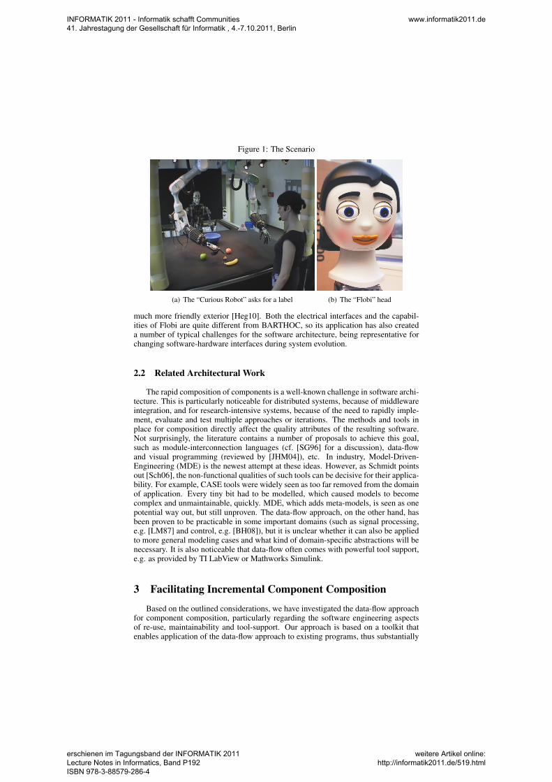
Figure 1: The Scenario
(a) The “Curious Robot” asks for a label (b) The “Flobi” head
much more friendly exterior [Heg10]. Both the electrical interfaces and the capabil-ities of Flobi are quite different from BARTHOC, so its application has also createda number of typical challenges for the software architecture, being representative forchanging software-hardware interfaces during system evolution.
2.2 Related Architectural Work
The rapid composition of components is a well-known challenge in software archi-tecture. This is particularly noticeable for distributed systems, because of middlewareintegration, and for research-intensive systems, because of the need to rapidly imple-ment, evaluate and test multiple approaches or iterations. The methods and tools inplace for composition directly affect the quality attributes of the resulting software.Not surprisingly, the literature contains a number of proposals to achieve this goal,such as module-interconnection languages (cf. [SG96] for a discussion), data-flowand visual programming (reviewed by [JHM04]), etc. In industry, Model-Driven-Engineering (MDE) is the newest attempt at these ideas. However, as Schmidt pointsout [Sch06], the non-functional qualities of such tools can be decisive for their applica-bility. For example, CASE tools were widely seen as too far removed from the domainof application. Every tiny bit had to be modelled, which caused models to becomecomplex and unmaintainable, quickly. MDE, which adds meta-models, is seen as onepotential way out, but still unproven. The data-flow approach, on the other hand, hasbeen proven to be practicable in some important domains (such as signal processing,e.g. [LM87] and control, e.g. [BH08]), but it is unclear whether it can also be appliedto more general modeling cases and what kind of domain-specific abstractions will benecessary. It is also noticeable that data-flow often comes with powerful tool support,e.g. as provided by TI LabView or Mathworks Simulink.
3 Facilitating Incremental Component Composition
Based on the outlined considerations, we have investigated the data-flow approachfor component composition, particularly regarding the software engineering aspectsof re-use, maintainability and tool-support. Our approach is based on a toolkit thatenables application of the data-flow approach to existing programs, thus substantially
INFORMATIK 2011 - Informatik schafft Communities 41. Jahrestagung der Gesellschaft für Informatik , 4.-7.10.2011, Berlin
www.informatik2011.de
erschienen im Tagungsband der INFORMATIK 2011 Lecture Notes in Informatics, Band P192 ISBN 978-3-88579-286-4
weitere Artikel online: http://informatik2011.de/519.html

Advances in Dataflow Programming Languages 3
Fig. 1. A simple program (a) and its dataflow equivalent (b).
2. THE DATAFLOW EXECUTION MODEL
2.1. The Pure Dataflow Model
In the dataflow execution model, a pro-gram is represented by a directed graph[Arvind and Culler 1986; Davis and Keller1982; Dennis 1974; Dennis and Misunas1975; Karp and Miller 1966]. The nodesof the graph are primitive instructionssuch as arithmetic or comparison oper-ations. Directed arcs between the nodesrepresent the data dependencies betweenthe instructions [Kosinski 1973]. Concep-tually, data flows as tokens along thearcs [Dennis 1974] which behave like un-bounded first-in, first-out (FIFO) queues[Kahn 1974]. Arcs that flow toward a nodeare said to be input arcs to that node, whilethose that flow away are said to be outputarcs from that node.
When the program begins, special acti-vation nodes place data onto certain keyinput arcs, triggering the rest of the pro-gram. Whenever a specific set of input arcsof a node (called a firing set) has data on it,the node is said to be fireable [Arvind andCuller 1986; Comte et al. 1978; Davis andKeller 1982]. A fireable node is executed atsome undefined time after it becomes fire-able. The result is that it removes a datatoken from each node in the firing set, per-forms its operation, and places a new data
token on some or all of its output arcs. Itthen ceases execution and waits to becomefireable again. By this method, instruc-tions are scheduled for execution as soonas their operands become available. Thisstands in contrast to the von Neumann ex-ecution model, in which an instruction isonly executed when the program counterreaches it, regardless of whether or not itcan be executed earlier than this.
The key advantage is that, in dataflow,more than one instruction can be executedat once. Thus, if several instructions be-come fireable at the same time, they can beexecuted in parallel. This simple principleprovides the potential for massive parallelexecution at the instruction level.
An example of dataflow versus a tra-ditional sequential program is shown inFigure 1. Figure 1(a) shows a fragment ofprogram code and Figure 1(b) shows howthis is represented as a dataflow graph.The arrows represent arcs, and the circlesrepresent instruction nodes. The squarerepresents a constant value, hard-codedinto the program. The letters representwhere data flows in or out of the rest ofthe program, which is not shown. Wheremore than one arrow emanates from agiven input, it means that the single valueis duplicated and transmitted down eachpath.
ACM Computing Surveys, Vol. 36, No. 1, March 2004.
(c) fine-grained data-flow program (from [JHM04])
2 7
s t a r t
Ac tua to rGraph$2Q u e u e H e a d S o u r c e
In j ec to rQueueHeadSource
e n d
C o m m a n d G e n e r a t o rMabotic.
Se r i a lSequenceCor re l a to r
SourceTagCorre la tor$2
[Tag. . . n == t rue ] ]
Conf i rmingOutpu tS t ream
[GraphSynchron ize r$1l eade r ]
(d) coarse-grained dataflow (from [Lu11])
Figure 2: Examples for data-flow programs of differing granularity.
lowering the bar for entry. While this toolkit has been newly developed, its imple-mentation is based on widely applied concepts – the difference is only in how we usethem. Specifically, we have adapted ideas from event-based integration to suggest thegranularity of data-flow nodes, a traditionally difficult issue. We suggest that re-use,in particular, will be increased by our proposal. Based on these ideas, several casestudies have been carried out, in the areas of information fusion, control drivers androbot behaviors. In comparative empirical analyses, we have examined the level ofre-use and the maintainability of the resulting component models, finding substantialimprovements in both. Lastly, we have also attempted to identify potential limits ofthe approach and how to overcome them. One result in this area regards global statemanagement and we will outline a potential mitigation strategy.
3.1 The Data-flow Model
Data-flow is based on a graph with the nodes specifying operations and the arcscarrying data between operations. This dates back at least to the 1970s, when it wasmotivated by hardware-level parallelism [JHM04]. Correspondingly, the nodes werevery fine-grained, down to individual instructions (cf. figure 2(c)). This was identifiedas inefficient and later approaches have used far bigger granularities, with our ownapproach using whole functional blocks as nodes (cf. figure 2(d)).
The graph in itself does not precisely specify the order of execution. Classically,data-flow is data-driven: Whenever the necessary data is available at the input(s) of anode, it will be processed and the result, if any, is placed on the output arc(s). Execu-
INFORMATIK 2011 - Informatik schafft Communities 41. Jahrestagung der Gesellschaft für Informatik , 4.-7.10.2011, Berlin
www.informatik2011.de
erschienen im Tagungsband der INFORMATIK 2011 Lecture Notes in Informatics, Band P192 ISBN 978-3-88579-286-4
weitere Artikel online: http://informatik2011.de/519.html

tion thus follows the data, as it flows through the graph – hence the name.The classical model assumes infinite hardware parallelism, which is not realiz-
able. The pure data-driven approach may also waste computation on results which arenot needed. Therefore, other models have been suggested, such as Kahn process net-works (KPN) [KM77]. These are demand-driven, i.e. nodes are only activated whentheir outputs are requested. Other models, such as SDF [LM87] use node-metadata tostatically schedule execution as needed. However, these approaches also come withcomplexity, are not always realizable (e.g. SDF still uses dynamic scheduling for con-ditionals) and are primarily necessary for fine-grained data-flow. Therefore, in ourapproach, we have opted for the classical data-driven execution. Our toolkit supportsboth one-thread-per-graph (optimized for minimal scheduling overhead) as well asone-thread-per-node (optimized for minimal latency) execution models.
3.2 The Filter-Transform-Select Decomposition Principle
The granularity of nodes has a major effect not only on the execution but also onmodeling and understanding of dataflow graphs. Our primary concern is the reduc-tion of unnecessary complexity, while increasing functional re-use. Taking inspira-tion from event-based integration [BCTW96], we suggest a decomposition into filters,transformations and selection (FTS) nodes [LSW09]. These are defined as follows:
Filter. A filter decides whether a particular graph section is used. This is directly rele-vant for re-use, as we may want to re-use functionality in different circumstancesthan originally envisioned.
Transform. The processing nodes themselves are transformations.
Select. Whenever there are multiple options, at least one of which must be taken, aselect node chooses the path. It is an error if no condition is met, which promotesa structured dataflow design that reduces mistakes.
Besides these distinctions, the decomposition also depends on the level of inter-est. For example, an algorithm often contains many conditions. As outlined above,describing a graph structure on that level is considered too fine. Therefore, the decom-position into filters, transformations and selectors is suggested to be performed at thehighest possible level, just below the component boundary.
As a last aspect, we have also carried forward these distinctions into a domain-specific-language for the creation of graphs. It separates the implementation fromthe model and, due to its higher level of specification, supports rapid application de-velopment. While our language is just a prototype so far, it has already been usedsuccessfully for several of the case studies presented in the following.
4 Case Studies
Our main interest has been to evaluate the applicability of the data-flow approachacross several domains. Therefore, we have conducted several case studies, where wecompare conventional implementations with FTS-based ones, as well as successiveiterations of data-flow applications. These allow us a quantitative assessment of thelevel of re-use seen and also feedback on the maintenance operations necessary, i.e.the maintainability.
It should be noted, however, that the intent of these comparisons is not to makeabsolute value judgments – far too many variables would be a factor. Instead, theintent is to gain insight into what kind of issues to expect when changing betweenapproaches. In the following, we will summarize the case studies and present our
INFORMATIK 2011 - Informatik schafft Communities 41. Jahrestagung der Gesellschaft für Informatik , 4.-7.10.2011, Berlin
www.informatik2011.de
erschienen im Tagungsband der INFORMATIK 2011 Lecture Notes in Informatics, Band P192 ISBN 978-3-88579-286-4
weitere Artikel online: http://informatik2011.de/519.html

RegionsSaliency Interest-Region
Figure 3: Typical input data (from [LPS+09]).
conclusions. The full studies are available as part of a PhD thesis [Lu11]. The graphi-cal representation of models is based on UML activity diagrams [UML05], with platemodel extension [Lu11].
4.1 Data fusion
The first object of study has been the action selection component in the “CuriousRobot” scenario [LPS+09, LPS+11]. Action selection is an important part of anyautonomous system. In such components, communication and interaction with othercomponents, as well as data fusion often make up a substantial part of the code. Theseare exactly the areas where we expect re-use potential. Furthermore, data fusion istypically tree structured, which constitutes a baseline processing case.
To realize action selection in this instance the following functions are necessary:Visual event receiption, ranking of visual regions, integration of background knowl-edge, selecting the most salient region and proposing an action that acquires the nextmost interesting piece of information. See figure 3 for example inputs and results.
An initial, independent version of the action selection component has been imple-mented by a colleague of the authors, for the first iteration of the “Curious Robot”demonstrator [LPS+09, section 2.D]. The implementation is small-to-mid-size, with778 source lines of code distributed amongst 22 classes, 5 of which are small innerclasses. From the code size, the basic COCOMO [Boe84] model would put such acomponent at 1.87 person-months, without overhead. While this may be an overesti-mate, given that it assumes a typical commercial development process, the componentinterfaces with many others, adding developer communication, so it seems realistic.
Re-use The component uses a middleware and associated marshaling routines.Otherwise, its implementation is primarily influenced by communication and data-management. The action selection implementation itself is simple, and thus fairlysmall, and distributed amongst the other code. This is not an ideal situation, if theselection algorithm would need to be upgraded.
After re-implementation using a data-flow formulation, the resulting graph consistsof 39 nodes, with 25 different types, containing 696 lines of code. Most importantly,only two node types are specific to the component, the other 23 are potentially genericand 13 (52%) of them have already been re-used in other, unrelated applications. Theremaining two nodes contain only 103 lines of code, with another 131 lines in thegraph model (using verbose XML syntax).
This high-level of re-use is consistent with expectations about such components,but has only been made actual through the data-flow based composition method. Theresulting graph is shown in figure 4.
Maintenance Having demonstrated a substantially increased level of re-use, wenow consider maintenance aspects. For this, we have added visualization functional-ity, displaying the inputs and choices of the component. This is mainly needed fordebugging, so we have realized it as an optional, second application. Ordinarily, such
INFORMATIK 2011 - Informatik schafft Communities 41. Jahrestagung der Gesellschaft für Informatik , 4.-7.10.2011, Berlin
www.informatik2011.de
erschienen im Tagungsband der INFORMATIK 2011 Lecture Notes in Informatics, Band P192 ISBN 978-3-88579-286-4
weitere Artikel online: http://informatik2011.de/519.html

s t a r t
MemorySourceShor tTerm
MemorySourceShor tTerm
MemorySourceShor tTerm
MemorySourceShor tTerm
e n d
ListClear
ListCollector
FusionSourceTag[ t a g = f u s e . b a c k g r o u n d ]
C o m p a r e A n d F u s e
TaggedFus ionNode
XPathSingleXPath = /*
[XPathMatcher...on/STATUS)]
AddChildElement
SetStat icAttr ibute
[XPathMatcher. . .serLabel)]]
SetStat icAttr ibute
[XPathMatcher.. .
SetStat icAttr ibute
[XPathMatcher...not(Grip)]]
D o c u m e n t F r o m
CurrentTime
DocumentSer ia l i ze r DocumentXOP
TextFrameTaskSubmiss ionTaskService on ShortTerm
XcfEventXOMDocumentXcfEvent
Unpackto-ObjectRegionArray
ArrayToList
[NonEmptyArray]
FusionSourceTag[ t ag=reg ions .ob j ec t s ]
RegionInfoRank
Count ingTaggedFusionNode
Packto-ObjectRegion
[Periodic. . . ter .@645fd]
FusionSourceTag[ t a g = f u s e . t a r g e t ]
XcfEventXOMDocumentXcfEvent
ListAdd
XcfEventXOMDocumentXcfEvent
Unpackto-SalientPointArray
RegionResolut ionScale
[NonEmptyArray]
ArrayToList
FusionSourceTag[ tag=reg ions . sa l i ency]
(a) upper part
s t a r t
MemorySourceShor tTerm
MemorySourceShor tTerm
MemorySourceShor tTerm
MemorySourceShor tTerm
e n d
ListClear
ListCollector
FusionSourceTag[ t a g = f u s e . b a c k g r o u n d ]
C o m p a r e A n d F u s e
TaggedFus ionNode
XPathSingleXPath = /*
[XPathMatcher...on/STATUS)]
AddChildElement
SetStat icAttr ibute
[XPathMatcher. . .serLabel)]]
SetStat icAttr ibute
[XPathMatcher.. .
SetStat icAttr ibute
[XPathMatcher...not(Grip)]]
D o c u m e n t F r o m
CurrentTime
DocumentSer ia l i ze r DocumentXOP
TextFrameTaskSubmiss ionTaskService on ShortTerm
XcfEventXOMDocumentXcfEvent
Unpackto-ObjectRegionArray
ArrayToList
[NonEmptyArray]
FusionSourceTag[ t ag=reg ions .ob j ec t s ]
RegionInfoRank
Count ingTaggedFusionNode
Packto-ObjectRegion
[Periodic. . . ter .@645fd]
FusionSourceTag[ t a g = f u s e . t a r g e t ]
XcfEventXOMDocumentXcfEvent
ListAdd
XcfEventXOMDocumentXcfEvent
Unpackto-SalientPointArray
RegionResolut ionScale
[NonEmptyArray]
ArrayToList
FusionSourceTag[ tag=reg ions . sa l i ency]
(b) lower part
Figure 4: Visual representation of the action selection component model.
a choice would result in substantial reimplementation, processing the same inputs, etc.However, in the data-flow approach using a textual model, all nodes can be re-usedand even the model only needs few modifications.
Specifically, to add visualization, 5 new node types have been added, mainly fordisplay and coloring. The modification operations consisted of three node insertions,an addition of a graph branch (for bringing up the GUI) and a removal of anotherbranch (which used to send out results). We consider this to be a very small numberof operations, thus the approach supports maintenance very well.
4.1.1 Case study 2: Hardware independent serial robot controlAfter looking at data-fusion, which is a popular but not particularly robotics-specificfunction, the second case-study will consider a subject closer to robotics, motor con-trol through a serial link. Such links are popular, as they allow to implement control
INFORMATIK 2011 - Informatik schafft Communities 41. Jahrestagung der Gesellschaft für Informatik , 4.-7.10.2011, Berlin
www.informatik2011.de
erschienen im Tagungsband der INFORMATIK 2011 Lecture Notes in Informatics, Band P192 ISBN 978-3-88579-286-4
weitere Artikel online: http://informatik2011.de/519.html

algorithms in a dedicated, real-time capable microcontroller with fairly low effort, butstill control them in detail from a more powerful host PC. It requires implementing acontrol protocol, however, which can be specific to the controller manufacturer.
The requirements for such protocols are as follows:
• Transduce abstract control commands to the vendor protocol and inversely forsensor data. This may sometimes be dependent on current device state.
• Manage access to the serial link – many protocols prohibit sending a commandbefore a reply for the previous one has been received.
• Realize a blend mode – protocols differ in whether a new command overwritesa previous one, is queued or is refused. Some protocols allow a choice, in othersthis must be realized through explicit queuing or cancellation.
• Deliver feedback information on start of command execution.
Study Design For this case study, a hardware independent layer for different robotshas been implemented. The robots are:
1. The BARTHOC humanoid torso [HSF+05], manufactured by MABOTIC GmbH.
2. The Sony EVI D31 Pan-Tilt-Zoom camera, using the VISCA protocol [Son99].This camera is common in many robotic applications and the protocol is alsoused for several other cameras by Sony.
3. The “Flobi” anthropomorphic robot head [LHS+10], developed jointly by Biele-feld University and MABOTIC GmbH. It uses an advanced protocol, based onideas from both of the above.
All of the above have been realized using the proposed approach. Regarding re-use, we have examined the size and make-up of the resulting graphs, summarized intable 1. More details and the full graphs are available in [Lu11].
Protocol #Nodes #Node types #Links #Custom nodesMABOTIC 11 11 10 2VISCA 31 25 51 14Flobi 14 12 20 5
Table 1: Protocol graph size summary
Reuse From this summary, it is obvious that the MABOTIC and Flobi protocolscould be realized with moderate effort and using only very few custom nodes. Thecustom ones are essentially just the transducers for input and output. The rest of thenodes could be re-used between protocols or from the standard node libraries. Suchstandard nodes include serial i/o, data combination, type filters, etc.
In contrast, the VISCA protocol required a much higher number of node types,much less of which are from the standard set. Furthermore, these nodes are also muchmore connected, in contrast to the earlier two protocols, which are mostly chains.The reason behind this is that the VISCA protocol keeps considerable state on thecontroller, some of which is necessary in creating command packets. This unfortunatefact requires the protocol implementation to keep a global state, which leads to a fairamount of connections in order to shuffle this state around. It shows that data-flowmodeling, with its local view of data, is not well suited to a global state.
INFORMATIK 2011 - Informatik schafft Communities 41. Jahrestagung der Gesellschaft für Informatik , 4.-7.10.2011, Berlin
www.informatik2011.de
erschienen im Tagungsband der INFORMATIK 2011 Lecture Notes in Informatics, Band P192 ISBN 978-3-88579-286-4
weitere Artikel online: http://informatik2011.de/519.html
3
s t a r t
Ac tua to rGraph$1Q u e u e H e a d S o u r c e
In j ec to rQueueHeadSource In j ec to rQueueHeadSource
e n d
ControlEventTransducer
Packe tGene ra to r
Ser ia lPor tGraph$1Serial Sink
Serial2Protocol$3WriteConfirm
ReadSenso rEven tTransduce r
[GraphSynchron ize r$1l eade r ]
(a) v1: read sync only
3
s t a r t
Ac tua to rGraph$1Q u e u e H e a d S o u r c e
In j ec to rQueueHeadSource In j ec to rQueueHeadSource
e n d
ControlEventTransducer
Packe tGene ra to r
[GraphSynchron ize r$1l eade r ]
Ser ia lPor tGraph$1Serial Sink
Serial2Protocol$3WriteConfirm
ReadSenso rEven tTransduce r
(b) v2: all commands synced
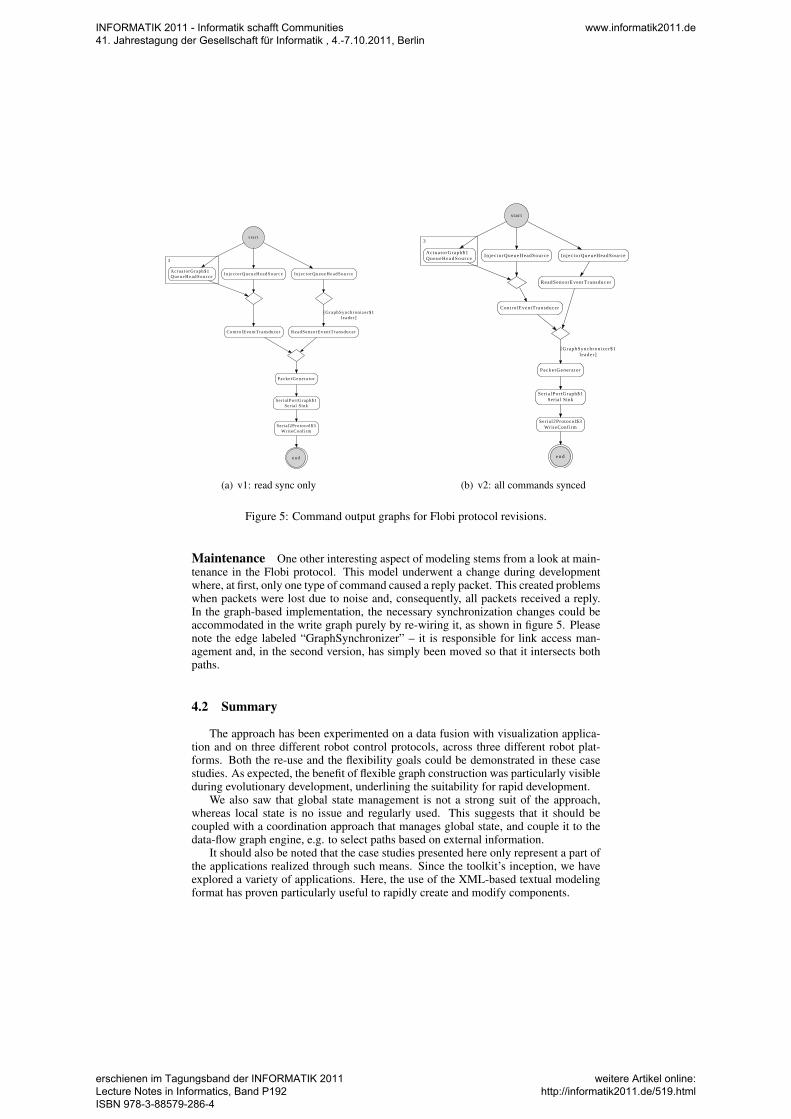
Figure 5: Command output graphs for Flobi protocol revisions.
Maintenance One other interesting aspect of modeling stems from a look at main-tenance in the Flobi protocol. This model underwent a change during developmentwhere, at first, only one type of command caused a reply packet. This created problemswhen packets were lost due to noise and, consequently, all packets received a reply.In the graph-based implementation, the necessary synchronization changes could beaccommodated in the write graph purely by re-wiring it, as shown in figure 5. Pleasenote the edge labeled “GraphSynchronizer” – it is responsible for link access man-agement and, in the second version, has simply been moved so that it intersects bothpaths.
4.2 Summary
The approach has been experimented on a data fusion with visualization applica-tion and on three different robot control protocols, across three different robot plat-forms. Both the re-use and the flexibility goals could be demonstrated in these casestudies. As expected, the benefit of flexible graph construction was particularly visibleduring evolutionary development, underlining the suitability for rapid development.
We also saw that global state management is not a strong suit of the approach,whereas local state is no issue and regularly used. This suggests that it should becoupled with a coordination approach that manages global state, and couple it to thedata-flow graph engine, e.g. to select paths based on external information.
It should also be noted that the case studies presented here only represent a part ofthe applications realized through such means. Since the toolkit’s inception, we haveexplored a variety of applications. Here, the use of the XML-based textual modelingformat has proven particularly useful to rapidly create and modify components.
INFORMATIK 2011 - Informatik schafft Communities 41. Jahrestagung der Gesellschaft für Informatik , 4.-7.10.2011, Berlin
www.informatik2011.de
erschienen im Tagungsband der INFORMATIK 2011 Lecture Notes in Informatics, Band P192 ISBN 978-3-88579-286-4
weitere Artikel online: http://informatik2011.de/519.html

XML Element Attributes Descriptionnode type, name, source Node of the given type, with optional name
and source node. If ’source’ is not given,uses predecessor in document order.
arg type Configuration argument for construction.select - Enclose a number of alternative paths.target - One of a number of alternatives.filter type Condition to be met for this path.fuse sources, required, outputType Combine output from n named nodes into
a map or pair.
Table 2: Slightly abbreviated summary of XML elements for model specifications.
5 Constructing Graphs
Originally, the component graphs have been created using the toolkit implementa-tion language (Java). This approach is still used at some places, but several drawbackswere reported by users of the toolkit. Most importantly, constructing the graph andspecifying parameters for the nodes is a configuration task which is conceptually quitedifferent from the implementation of nodes. Furthermore, from a program understand-ing point of view, it might be too easy to bypass the intended method of passing data(edges) though shared state variables. These make it much harder for the engine to en-sure scheduling constraints, and they also add complexity to analysis and monitoring.
5.1 XML syntax for data-flow graphs
As a first step to address these issues, an XML-based configuration language hasbeen created, based on four constructs: i) node configuration (including naming), ii)implicit and explicit linkage between nodes to create edges, iii) fusion constructs tocombine data, and iv) selection. See table 2 for an overview, listing 1 for a simpleexample and figure 6 for the resulting graph structure.
Listing 1: Example graph processing two different XML-based sources1 <model>2 <node name=” f i b ” t y p e =” XMLFibonacciSource ” />3 <node name=” t ime ” s o u r c e =” n u l l ” t y p e =” XMLTimestampSource ” />4 <s e l e c t name=” c h o i c e 1 ” s o u r c e =” f i b , t ime ” s e l e c t M a x =” 1 ”>5 < t a r g e t>6 < f i l t e r t y p e =” X P a t h F i l t e r ”>7 <a r g t y p e =” S t r i n g C h i l d ”>/ f i b o n a c c i</ a r g>8 </ f i l t e r>9 <node t y p e =” X P a t h T r a n s f o r m S i n g l e ”>
10 <a r g t y p e =” S t r i n g C h i l d ”>number ( / f i b o n a c c i / v a l u e )</ a r g>11 </ node>12 </ t a r g e t>13 < t a r g e t>14 < f i l t e r t y p e =” X P a t h F i l t e r ”>15 <a r g t y p e =” S t r i n g C h i l d ”>/∗</ a r g>16 </ f i l t e r>17 <node t y p e =” X P a t h T r a n s f o r m S i n g l e ”>18 <a r g t y p e =” S t r i n g C h i l d ”>s t r i n g ( . )</ a r g>19 </ node>20 </ t a r g e t>21 </ s e l e c t>22 <node name=” s t a t i c ” s o u r c e =” n u l l ” t y p e =” S t a t i c S o u r c e ”>23 <a r g t y p e =” S t r i n g C h i l d ”>some th ing e l s e</ a r g>24 </ node>25 <f u s e s o u r c e s =” cho ice1 , s t a t i c ” r e q u i r e d =” cho ice1 , s t a t i c ” />26 <node t y p e =” QueueSink ” />27 </ model>
INFORMATIK 2011 - Informatik schafft Communities 41. Jahrestagung der Gesellschaft für Informatik , 4.-7.10.2011, Berlin
www.informatik2011.de
erschienen im Tagungsband der INFORMATIK 2011 Lecture Notes in Informatics, Band P192 ISBN 978-3-88579-286-4
weitere Artikel online: http://informatik2011.de/519.html

SourceAdapter[name=XOM fibonacci]
Node[name=SelectFirst]
TagStrip TagStrip
XPath[string(.)]
FusionSourceTagNode[tag=choice1]
RequiredNamesTaggedFusionNode[names=[choice1, static], useOnceOnly=true]
Node[name=QueueSink]
XPath[number(/fibonacci/value)]
StaticSource[something else]
FusionSourceTagNode[tag=static]
SourceAdapter[name=XOM timestamp]
Figure 6: Graph corresponding to listing 1
At this moment, our graph specifications usually run to between 100 and 700 linesof XML, with much of that taken up by configuration expressions. These representcomponents that, while sometimes not overly complex, are still fully running appli-cations. For example, the robot behaviors from [Lu11, chapter 8 and 9], are real-ized using such models. The present author has so far used about 140 different nodetypes, with functionality such as middleware connectivity (three different ones), datamarshaling, XML parsing, selection and transformation, simple GUIs, finite-state-machines, file and serial line I/O, as well as some utility types, for data manipulation,fusion, and selection.
6 Discussion
While the proposed approach is certainly not a widely used project so far, it hasnow been successfully applied in several projects at Bielefeld University for aboutthree years, by both students and researchers. In these projects, it has been easilyadopted, largely due to its low cost of entry, and use of familiar concepts. Basedon this experience, we will now discuss some aspects that we consider of particularinterest to Software Language Engineering.
6.1 Granularity
We have initially focused the framework on the granularity issue, by suggestingthe FTS decomposition, because we believe that addressing it is key to achieve re-usability: Re-usable chunks should be large enough to be worth-while, but not solarge as to be overly specific. That said, we do not claim to have identified the onetrue granularity. Granularity is always a matter of the detail level: What is a puretransformation on one level of view may very well have many conditions and branchescontained in its implementation. Thus, the FTS decomposition is more about extract-ing the filter that determines when to apply a transformation at all. This is the part thatwe have seen to change across different domains.
INFORMATIK 2011 - Informatik schafft Communities 41. Jahrestagung der Gesellschaft für Informatik , 4.-7.10.2011, Berlin
www.informatik2011.de
erschienen im Tagungsband der INFORMATIK 2011 Lecture Notes in Informatics, Band P192 ISBN 978-3-88579-286-4
weitere Artikel online: http://informatik2011.de/519.html

Otherwise, when looking at multiple similar components, determining good gran-ularity may not be as difficult as initially thought: Pick blocks that re-occur acrossapplications. Here, the main contribution may very well have been to supply a frame-work that emphasizes this issue and, thus, both makes people aware that composingcomponents as a graph of small parts may be a good approach, and assists them indoing so.
6.2 Re-use and Configuration
As the case studies presented have shown, the proposed approach could achieve itsre-use goal. It has been asked whether this is due to a second system effect: A laterre-implementation could benefit from an improved understanding of a good problemdecomposition. This may be, but for several aspects that have seen increased re-use,such as middleware communication, even the developers of the original componentsalready had a good understanding of the problem.
We believe that the seperation of configuration, composition, and computation ismore crucial. The seperation of composition from computation has been the initialpoint of adopting a data-flow approach and, thus, has been expected. The more in-teresting effect is based on the use of configuration expressions. These have been analmost inadvertant side-effect of the use of a textual specification language: Becausearguments could not be constructed from multiple objects as easily, a textual expres-sion language has been added instead. In some cases, such a language has alreadybeen used before, e.g. we widely used XPath for conditions and selectors on XMLdocuments. This experience and its good results, then, led to the adoption of the JEXLexpression language for specifying conditions on other kinds of objects.
6.3 Experiences with the graph specification language
While the described XML syntax has only been intended as a quick stepping stone,some of its design choices have shown themselves to be both unexpectedly convenientand unexpectedly inconvenient.
Implicit connectivity In contrast to existing graph specification languages, ourspecialized language has been designed for using implicit linkage between nodes asmuch as possible. In this mode, unless specified otherwise, two node definitions thatfollow each other in document order are linked into a chain. When we set out to designthe specification, our graphs primarily contained chains, with junction nodes beingmuch rarer. Therefore, using the XML document order when no explicit predecessoris given saves typing, and also makes re-ordering and inserting nodes easier.
In fact, after having used this implicit way of making connections, we consider itindespensible, and would ask for it in any future tool. A comparison to graphical toolshas been illuminating here. In principle, one would expect a visual tool for creatinggraphs to be very natural, and we believe that a visual tool would hold much promisefor our approach, too. However, many graphical tools for creating graphs use a boxes-and-arrows model, where edges have to be explicitly specified, and changed, wheneverconnectivity changes. This makes, for example, moving a node a six-step operation(1: remove incoming link, 2: remove outgoing link, 3: link previous neighbors, 4:remove outgoing link from new predecessor, 5: link new predecessor as incoming, 6:link node to successor), whereas with implicit linkage, it is a two-step operation (1:cut, 2: paste). The same holds for other manipulations. In our opinion, visual toolsthus need specialized means to achieve connectivity.
INFORMATIK 2011 - Informatik schafft Communities 41. Jahrestagung der Gesellschaft für Informatik , 4.-7.10.2011, Berlin
www.informatik2011.de
erschienen im Tagungsband der INFORMATIK 2011 Lecture Notes in Informatics, Band P192 ISBN 978-3-88579-286-4
weitere Artikel online: http://informatik2011.de/519.html
Verbosity and Generation Using XML as the syntax creates a fairly verbosespecification syntax which is comparatively tedious to create. While the approach hasserved us reasonably well so far, we expect that scaling it up to larger components willlikely require different methods.
That said, in several important cases, our current graph specifications substantiallyconsist out of configuration expressions, not XML. For example, we embedded state-machine specifications, or XQuery expressions (XQuery, while being designed forXML processing, is essentially on an SQL-level of verbosity). For such cases, weconsider the XML overhead to be insignificant.
On option to shorten the specifications, while keeping XML, that have already ex-perimented with is generating the specification from a more domain-specific specifi-cation language, which is expected to result in shorter specifications. The tool supportfor XML, such as mature support for XSLT transformations, has made such generationapproaches straightforward.
Wiring for data combination While the two points above have been unexpect-edly positive, one aspect of the current syntax has also proven an unexpected issue:Collection manipulation for data combination. The way we have implemented this isthat whenever a node requires more than one input element, these will be fused into aMap with string keys by the “fuse” element. One unfortunate consequence of this im-plementation choice is that it requires more knowledge about the implementation of anode at configuration time (the expected key names), which is also harder to determineautomatically, in contrast to the type information for construction, which is availablethrough reflection. Moreover, once fused, a map may require taking apart again, fornodes that process only one of its elements. At the moment, the specification languagehas no explicit support for such operations, requiring them to be carried out throughtransformation nodes. This is clearly sub-optimal.
At the moment, we are undecided as to how to address this best. While it mayappear a simple solution to implement nodes with multiple arguments, we have somereservations on the grounds of clarity and predictability. In general, however, lan-guage support to move this collection manipulation into the background is definitelydesirable and planned as a next step.
6.4 Language Tools
One noticeable draw-back when using XML for specification is a lack of moderndevelopment tool support. For example, there is no completion or checking for typenames (which represent the operations, and are essentially an open set, hence not easilyspecifiable using schemata), and no suggestion of argument values. While this is notvery different to how much programming used to occur before the advent of IDE’s,nowadays it feels decidedly inconvenient. We expect that such issues are rather easyto solve, but they add to the development burden for a DSL.
A more serious issue is that the data-flow approach changes debugging. All user-code is called by an external engine, similar to the Inversion-of-Control style of userinterface toolkits. Tracing code execution through this engine is very different fromtraditional debugging, because user code and framework code is interleaved tightly.This is somewhat offset by the fact that the separation of functionality into well-definedbuilding blocks can make other development tasks, such as unit-testing, easier. How-ever, it is still by no means optimal. A debugger with an awareness of the differentexecution model imposed by the data-flow engine would be one approach to address-ing this issue.
INFORMATIK 2011 - Informatik schafft Communities 41. Jahrestagung der Gesellschaft für Informatik , 4.-7.10.2011, Berlin
www.informatik2011.de
erschienen im Tagungsband der INFORMATIK 2011 Lecture Notes in Informatics, Band P192 ISBN 978-3-88579-286-4
weitere Artikel online: http://informatik2011.de/519.html

7 Conclusion
We have presented a graph-based approach for composing components from re-usable building blocks, that achieves higher re-usability by introducing a middle gran-ularity level, below full components, but above the functional level. To complementthis, we have proposed a decomposition approach based on event-based systems, thefilter-transform-select (FTS) decomposition. In several case studies, we could showthat this approach can lead to drastically improved re-use.
Furthermore, we have presented experience reports on using a simple, XML-basedlanguage to specify the component graphs. This language aids construction, by provid-ing an easily changed configuration language. Furthermore, it is based on the conceptof implicit linkage, which we believe to be an essential feature for data-flow configura-tion languages, both textual and graphical. From these reports, we have provided somerequirements for future work in software language engineering that will be valueablein this direction.
References
[BCTW96] Daniel J. Barrett, Lori A. Clarke, Peri L. Tarr, and Alexander E. Wise. Aframework for event-based software integration. ACM Trans. Softw. Eng.Methodol., 5(4):378–421, 1996.
[BH08] B. Bauml and G. Hirzinger. When hard realtime matters: Softwarefor complex mechatronic systems. Robotics and Autonomous Systems,56(1):5–13, January 2008.
[Boe84] Barry W. Boehm. Software Engineering Economics. IEEE Transactionson Software Engineering, SE-10(1):4–21, January 1984.
[BsK03] H. Bruyninckx, P. soetens, and B. Koninchx. The real-time motion controlcore of the orocos project. In Proc. IEEE Int. Conf. on Robotics andAutomation (ICRA), pages 2766–2771, Taipei, Taiwan, Sept. 2003.
[Heg10] Frank Hegel. Gestalterisch konstruktiver Entwurf eines sozialen Robot-ers. PhD thesis, Bielefeld University, 2010.
[HSF+05] M. Hackel, St. Schwope, J. Fritsch, B. Wrede, and G. Sagerer. A Hu-manoid Robot Platform Suitable for Studying Embodied Interaction. InProc. IEEE/RSJ Int. Conf. on Intelligent Robots and Systems. IEEE, 2005.
[JHM04] Wesley M. Johnston, J. R. Paul Hanna, and Richard J. Millar. Advancesin dataflow programming languages. ACM Comput. Surv., 36(1):1–34,March 2004.
[KM77] Gilles Kahn and David MacQueen. Coroutines and networks of parallelprocesses. In B. Gilchrist, editor, Information Processing ’77: Proceed-ings of IFIP Congress, pages 993–998, Amsterdam, The Netherlands,1977. North-Holland Publishing Co.
[Lu11] Ingo Lutkebohle. Coordination and Composition Patterns in the “Curi-ous Robot” Scenario. PhD thesis, Bielefeld University, 2011. in press.
[LHS+10] Ingo Lutkebohle, Frank Hegel, Simon Schulz, Matthias Hackel, BrittaWrede, Sven Wachsmuth, and Gerhard Sagerer. The Bielefeld Anthropo-morphic Robot Head “Flobi”. In 2010 IEEE International Conference onRobotics and Automation, Anchorage, Alaska, 2010. IEEE.
INFORMATIK 2011 - Informatik schafft Communities 41. Jahrestagung der Gesellschaft für Informatik , 4.-7.10.2011, Berlin
www.informatik2011.de
erschienen im Tagungsband der INFORMATIK 2011 Lecture Notes in Informatics, Band P192 ISBN 978-3-88579-286-4
weitere Artikel online: http://informatik2011.de/519.html

[LM87] E. A. Lee and D. G. Messerschmitt. Synchronous data flow. Proceedingsof the IEEE, 75(9), 1987.
[LPS+09] Ingo Lutkebohle, Julia Peltason, Lars Schillingmann, Christof Elbrechter,Britta Wrede, Sven Wachsmuth, and Robert Haschke. The Curious Robot- Structuring Interactive Robot Learning. In International Conferenceon Robotics and Automation, Kobe, Japan, May 2009. Robotics and Au-tomation Society, IEEE.
[LPS+11] Ingo Lutkebohle, Julia Peltason, Lars Schillingmann, Christof Elbrechter,Sven Wachsmuth, Britta Wrede, and Robert Haschke. Realizing a RobotSystem for Interactive Online Learning. In Towards Service Robots forEveryday Environments. Springer Verlag, 2011. forthcoming.
[LSW09] Ingo Lutkebohle, Jan Schaefer, and Sebastian Wrede. Facilitating Re-Use by Design: A Filtering, Transformation, and Selection Architecturefor Robotic Software Systems. In Workshop on Software Developmentand Integration in Robotics, Kobe, Japan, 2009.
[LW11] Ingo Lutkebohle and Sven Wachsmuth. Event-oriented Incremental Com-ponent Construction. In Towards Service Robots for Everyday Environ-ments. Springer Verlag, 2011. forthcoming.
[Nes07] I.A. Nesnas. The clarity project: Coping with hardware and software het-erogenity. Software engineering for experimental robotics (Series STAR),30, 2007.
[QCG+09] Morgan Quigley, Ken Conley, Brian P. Gerkey, Josh Faust, Tully Foote,Jeremy Leibs, Rob Wheeler, and Andrew Y. Ng. ROS: an open-sourceRobot Operating System. In ICRA Workshop on Open Source Software,2009.
[RHSR07] Frank Rothling, R. Haschke, Jochen J. Steil, and Helge J. Ritter. PlatformPortable Anthropomorphic Grasping with the Bielefeld 20-DOF Shadowand 9-DOF TUM Hand. In Proc. Int. Conf. on Intelligent Robots andSystems (IROS). IEEE, 2007.
[Sch06] Douglas C. Schmidt. Guest Editor’s Introduction: Model-Driven Engi-neering. COMPUTER, 39(02):25–31, 2006.
[Sch07] C. Schlegel. Communication patterns as a key towards component in-teroperability. Software engineering for experimental robotics (SeriesSTAR), 30:183–210, 2007.
[SG96] Mary Shaw and David Garlan. Software Architecture: Perspectives on anEmerging Discipline. Prentice Hall, April 1996.
[Son99] Sony Corporation, 4-16-1, Okata, Atsugi-shi, Kanagawa-ken, 243-0021Japan. Command list – Intelligent Communication Color Video CameraEVI-D30/D31, v1.21, english edition, 1999.
[UML05] Unified Modeling Language: Superstructure version 2.0. Technical re-port, Object Management Group (OMG), Inc, 2005.
INFORMATIK 2011 - Informatik schafft Communities 41. Jahrestagung der Gesellschaft für Informatik , 4.-7.10.2011, Berlin
www.informatik2011.de
erschienen im Tagungsband der INFORMATIK 2011 Lecture Notes in Informatics, Band P192 ISBN 978-3-88579-286-4
weitere Artikel online: http://informatik2011.de/519.html