requirements definition and specification u …bmitchell/course/mcs451/ch_7_1.pdf · requirements...
TRANSCRIPT

©Ian Sommerville 1995 Software Engineering, 5th edition. Chapter 7 Slide
RequirementsDefinition and Specification
u Techniques for defining andspecifying software systemrequirements
©Ian Sommerville 1995 Software Engineering, 5th edition. Chapter 7 Slide
Objectivesu To illustrate a forms-based method of writing
requirements definitionu To describe ways of writing precise specificationsu To explain the importance of non-functional
requirementsu To describe different types of non-functional
requirement and how these can be specified

©Ian Sommerville 1995 Software Engineering, 5th edition. Chapter 7 Slide
Topics coveredu Requirements definitionu Requirements specificationu Non-functional requirements

©Ian Sommerville 1995 Software Engineering, 5th edition. Chapter 7 Slide
Definition and specificationu Requirements definition
• Customer-oriented descriptions of the system’s functions andconstraints on its operation
u Requirements specification• Precise and detailed descriptions of the system’s functionality
and constraints. Intended to communicate what is required tosystem developers and serve as the basis of a contract for thesystem development
©Ian Sommerville 1995 Software Engineering, 5th edition. Chapter 7 Slide
Requirements definitionu Should specify external behaviour of the system
so the requirements should not be defined using acomputational model
u Includes functional and non-functionalrequirements• Functional requirements are statements of the services that the
system should provide• Non-functional requirements are constraints on the services and
functions offered by the system

©Ian Sommerville 1995 Software Engineering, 5th edition. Chapter 7 Slide
Writing requirements definitionsu Natural language, supplemented by diagrams and
tables is the normal way of writing requirementsdefinitions
u This is universally understandable but three typesof problem can arise• Lack of clarity. Precision is difficult without making the
document difficult to read• Requirements confusion. Functional and non-functional
requirements tend to be mixed-up• Requirements amalgamation. Several different requirements
may be expressed together

©Ian Sommerville 1995 Software Engineering, 5th edition. Chapter 7 Slide
APSE database requirement
4.A.5 The database shall support the generation and control of configuration objects; that is, objects which are themselves groupings of other objects in the database. The configuration control facilities shall allow access to the objects in a version group by the use of an incomplete name.

©Ian Sommerville 1995 Software Engineering, 5th edition. Chapter 7 Slide
Editor grid requirement
2.6 Grid facilities To assist in the positioning of entities on a diagram, the user may turn on a grid in either centimetres or inches, via an option on the control panel. Initially, the grid is off. The grid may be turned on and off at any time during an editing session and can be toggled between inches and centimetres at any time. A grid option will be provided on the reduce-to-fit view but the number of grid lines shown will be reduced to avoid filling the smaller diagram with grid lines.
©Ian Sommerville 1995 Software Engineering, 5th edition. Chapter 7 Slide
Defining requirementsu Editor requirement mixes up functional and non-
functional requirements and is incompleteu Easy to criticise but hard to write good
requirements definitionsu Use of a standard format with pre-defined fields
to be filled means that information is less likelyto be missed out

©Ian Sommerville 1995 Software Engineering, 5th edition. Chapter 7 Slide
Editor grid definition2.6 Grid facilities
2.6.1 The editor shall provide a grid facility where a matrix of horizontal andvertical lines provide a background to the editor window. This grid shallbe a passive grid where the alignment of entities is the user's responsibility.Rationale: A grid helps the user to create a tidy diagram with well-spacedentities. Although an active grid, where entities 'snap-to' grid lines can beuseful, the positioning is imprecise. The user is the best person to decidewhere entities should be positioned.
2.6.2 When used in ‘reduce-to-fit’ mode (see 2.1), the number of unitsseparating grid lines must be increased.Rationale: If line spacing is not increased, the background will be very cluttered with grid lines.
Specification: ECLIPSE/WS/Tools/DE/FS Section 5.6

©Ian Sommerville 1995 Software Engineering, 5th edition. Chapter 7 Slide
Requirements rationaleu It is important to provide rationale with
requirementsu This helps the developer understand the
application domain and why the requirement isstated in its current form
u Particularly important when requirements have tobe changed. The availability of rationale reducesthe chances that change will have unexpectedeffects

©Ian Sommerville 1995 Software Engineering, 5th edition. Chapter 7 Slide
Node creation definition3.5.1 Adding nodes to a design
3.5.1.1 The editor shall provide a facility where users can add nodes of a specified type to a design. Nodes are selected (see 3.4) when they are added to the design.
3.5.1.2 The sequence of actions to add a node should be as follows:1. The user should select the type of node to be added. 2. The user moves the cursor to the approximate node position in the diagram and indicates that the node symbol should be added at that point.3. The symbol may then be dragged to its final position.
Rationale: The user is the best person to decide where to position a node on the diagram. This approach gives the user direct control over node type selection and positioning.
Specification: ECLIPSE/WS/Tools/DE/FS. Section 3.5.1
©Ian Sommerville 1995 Software Engineering, 5th edition. Chapter 7 Slide
Requirements specificationu The specifications adds detail to the requirements
definition. It should be consistent with it.u Usually presented with system models which are
developed during the requirements analysis.These models may define part of the system to bedeveloped
u Often written in natural language but this can beproblematical

©Ian Sommerville 1995 Software Engineering, 5th edition. Chapter 7 Slide
Problems with natural languageu Natural language relies on the specification
readers and writers using the same words for thesame concept
u A natural language specification is over-flexibleand subject to different interpretations
u Requirements are not partitioned by languagestructures
©Ian Sommerville 1995 Software Engineering, 5th edition. Chapter 7 Slide
Natural language alternativesu Structured natural languageu Design description languagesu Requirements specification languagesu Graphical notationsu Mathematical specifications
©Ian Sommerville 1995 Software Engineering, 5th edition. Chapter 7 Slide
Requirements traceabilityu Requirements traceability means that related
requirements are linked in some way and thatrequirements are (perhaps) linked to their source
u Traceability is a property of a requirementsspecification which reflects the ease of findingrelated requirements
u Some CASE tools provide traceability supportfacilities. For example, they may be able to findall requirements which use the same terms

©Ian Sommerville 1995 Software Engineering, 5th edition. Chapter 7 Slide
Traceability techniquesu Assign a unique number to all requirementsu Cross-reference related requirements using this
unique numberu Produce a cross-reference matrix for each
requirements document showing relatedrequirements. Several matrices may be necessaryfor different types of relationship

©Ian Sommerville 1995 Software Engineering, 5th edition. Chapter 7 Slide
Structured language specificationsu A limited form of natural language may be used
to express requirementsu This removes some of the problems resulting
from ambiguity and flexibility and imposes adegree of uniformity on a specification
u Often bast supported using a forms-basedapproach

©Ian Sommerville 1995 Software Engineering, 5th edition. Chapter 7 Slide
Form-based specificationsu Definition of the function or entityu Description of inputs and where they come fromu Description of outputs and where they go tou Indication of other entities requiredu Pre and post conditions (if appropriate)u The side effects (if any)

©Ian Sommerville 1995 Software Engineering, 5th edition. Chapter 7 Slide
Form-based node specificationECLIPSE/Workstation/Tools/DE/FS/3.5.1
Function Add node
Description Adds a node to an existing design. The user selects the type of node, and its position.When added to the design, the node becomes the current selection. The user chooses the node position bymoving the cursor to the area where the node is added.
Inputs Node type, Node position, Design identifier.
Source Node type and Node position are input by the user, Design identifier from the database.
Outputs Design identifier.
Destination The design database. The design is committed to the database on completion of theoperation.
Requires Design graph rooted at input design identifier.
Pre-condition The design is open and displayed on the user's screen.
Post-condition The design is unchanged apart from the addition of a node of the specified typeat the given position.
Side-effects None
Definition: ECLIPSE/Workstation/Tools/DE/RD/3.5.1

©Ian Sommerville 1995 Software Engineering, 5th edition. Chapter 7 Slide
PDL-based requirements definitionu Requirements may be defined operationally using
a language like a programming language but withmore flexibility of expression
u Most appropriate in two situations• Where an operation is specified as a sequence of actions and the
order is important• When hardware and software interfaces have to be specified
u Disadvantages are• The PDL may not be sufficiently expressive to define domain
concepts• The specification will be taken as a design rather than a
specification
©Ian Sommerville 1995 Software Engineering, 5th edition. Chapter 7 Slide
PDL description of an ATMu Replace with portrait slide

©Ian Sommerville 1995 Software Engineering, 5th edition. Chapter 7 Slide
Interface specificationu Almost all software systems operate in an
environment where there are other systems. Theymay be interfaces to these systems in differentways
u Three types of interface may have to be definedin a requirements specification• Procedural interfaces. Sub-systems offer a range of services• Data interfaces. Data structures are exchanged• Representation interfaces. Specific data representation patterns
may have to be used

©Ian Sommerville 1995 Software Engineering, 5th edition. Chapter 7 Slide
Procedural interface example
package Print_server isprocedure Initialise (P: PRINTER) ;procedure Print (P: PRINTER ; F: PRINT_FILE ) ;
procedure Display_print_queue (P: PRINTER ) ;procedure Cancel_print_job (P: PRINTER; N: PRINT_ID) ;procedure Switch_printer (P1, P2: PRINTER; N: PRINT_ID) ;
end Print_server ;
©Ian Sommerville 1995 Software Engineering, 5th edition. Chapter 7 Slide
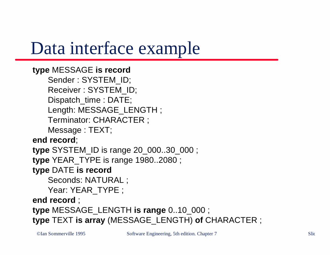
Data interface exampletype MESSAGE is record Sender : SYSTEM_ID;
Receiver : SYSTEM_ID;Dispatch_time : DATE;Length: MESSAGE_LENGTH ;Terminator: CHARACTER ;Message : TEXT;
end record;type SYSTEM_ID is range 20_000..30_000 ;type YEAR_TYPE is range 1980..2080 ;type DATE is record
Seconds: NATURAL ;Year: YEAR_TYPE ;
end record ;type MESSAGE_LENGTH is range 0..10_000 ;type TEXT is array (MESSAGE_LENGTH) of CHARACTER ;
©Ian Sommerville 1995 Software Engineering, 5th edition. Chapter 7 Slide
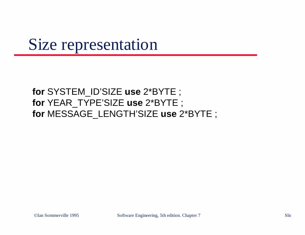
Size representation
for SYSTEM_ID’SIZE use 2*BYTE ;for YEAR_TYPE’SIZE use 2*BYTE ;for MESSAGE_LENGTH’SIZE use 2*BYTE ;

©Ian Sommerville 1995 Software Engineering, 5th edition. Chapter 7 Slide
Representation interface example
type STATE is (Halted, Waiting, Ready, Running);for STATE use (Halted => 1, Waiting => 4, Ready => 16,
Running => 256);
©Ian Sommerville 1995 Software Engineering, 5th edition. Chapter 7 Slide
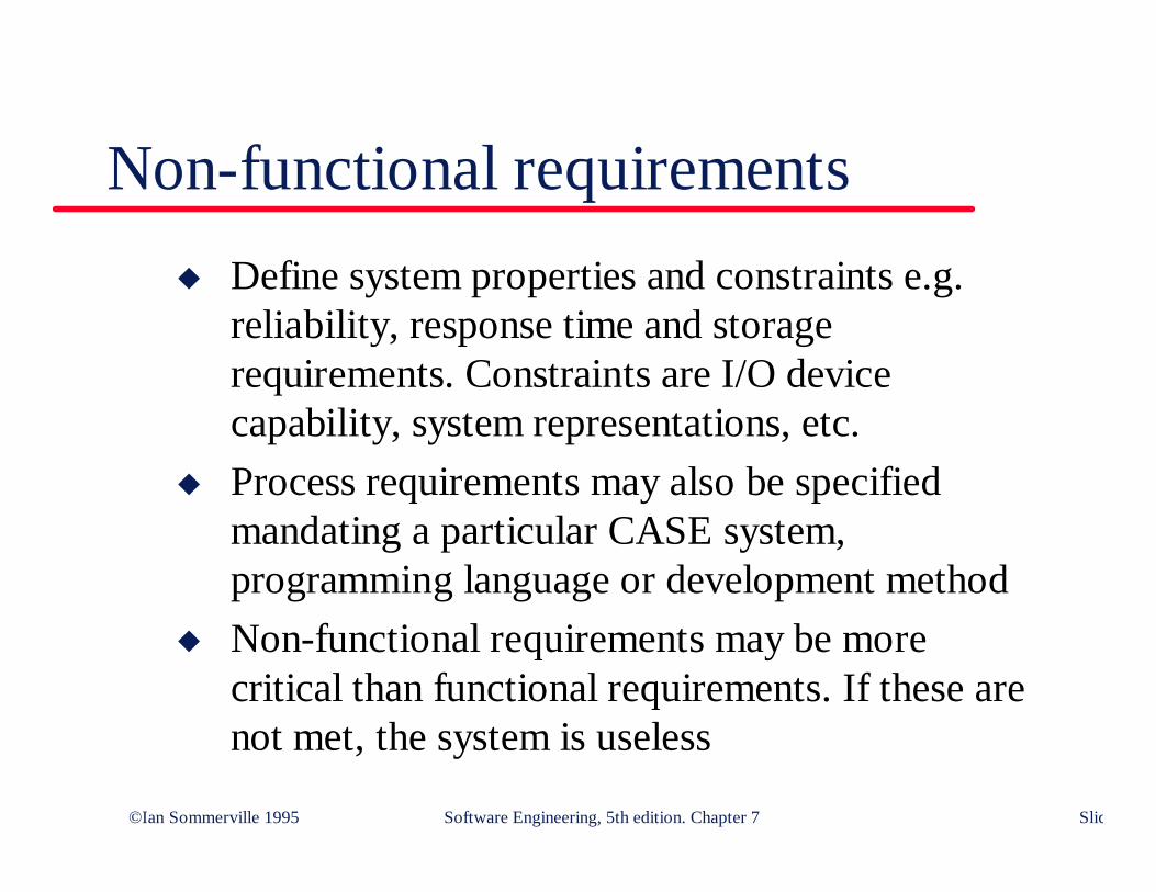
Non-functional requirementsu Define system properties and constraints e.g.
reliability, response time and storagerequirements. Constraints are I/O devicecapability, system representations, etc.
u Process requirements may also be specifiedmandating a particular CASE system,programming language or development method
u Non-functional requirements may be morecritical than functional requirements. If these arenot met, the system is useless
©Ian Sommerville 1995 Software Engineering, 5th edition. Chapter 7 Slide
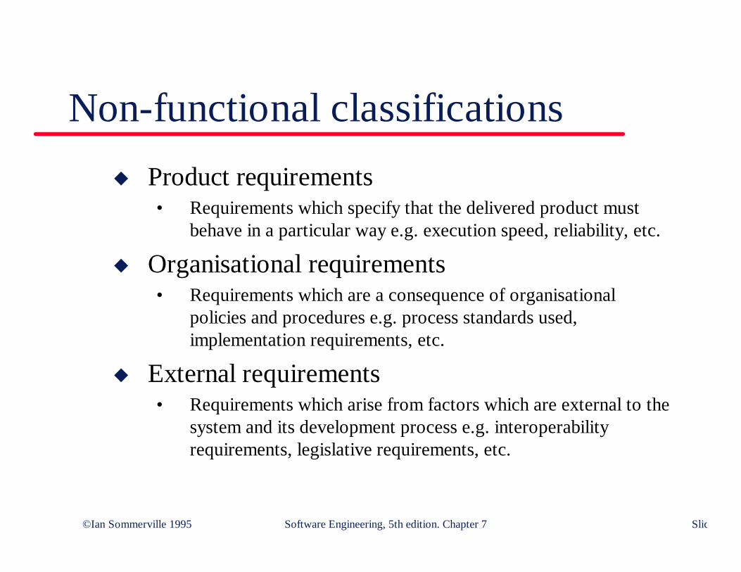
Non-functional classificationsu Product requirements
• Requirements which specify that the delivered product mustbehave in a particular way e.g. execution speed, reliability, etc.
u Organisational requirements• Requirements which are a consequence of organisational
policies and procedures e.g. process standards used,implementation requirements, etc.
u External requirements• Requirements which arise from factors which are external to the
system and its development process e.g. interoperabilityrequirements, legislative requirements, etc.

©Ian Sommerville 1995 Software Engineering, 5th edition. Chapter 7 Slide
Non-functional requirement types
Performancerequirements
Spacerequirements
Usabil ityrequirements
Ef ficiencyrequirements
Reliabil ityrequirements
Portabil ityrequirements
Interoperabil ityrequirements
Ethicalrequirements
Legislativerequirements
Implementationrequirements
Standardsrequirements
Del iveryrequirements
Safetyrequirements
Privacyrequirements
Productrequirements
Organizationalrequirements
Externalrequirements
Non-functionalrequirements
©Ian Sommerville 1995 Software Engineering, 5th edition. Chapter 7 Slide
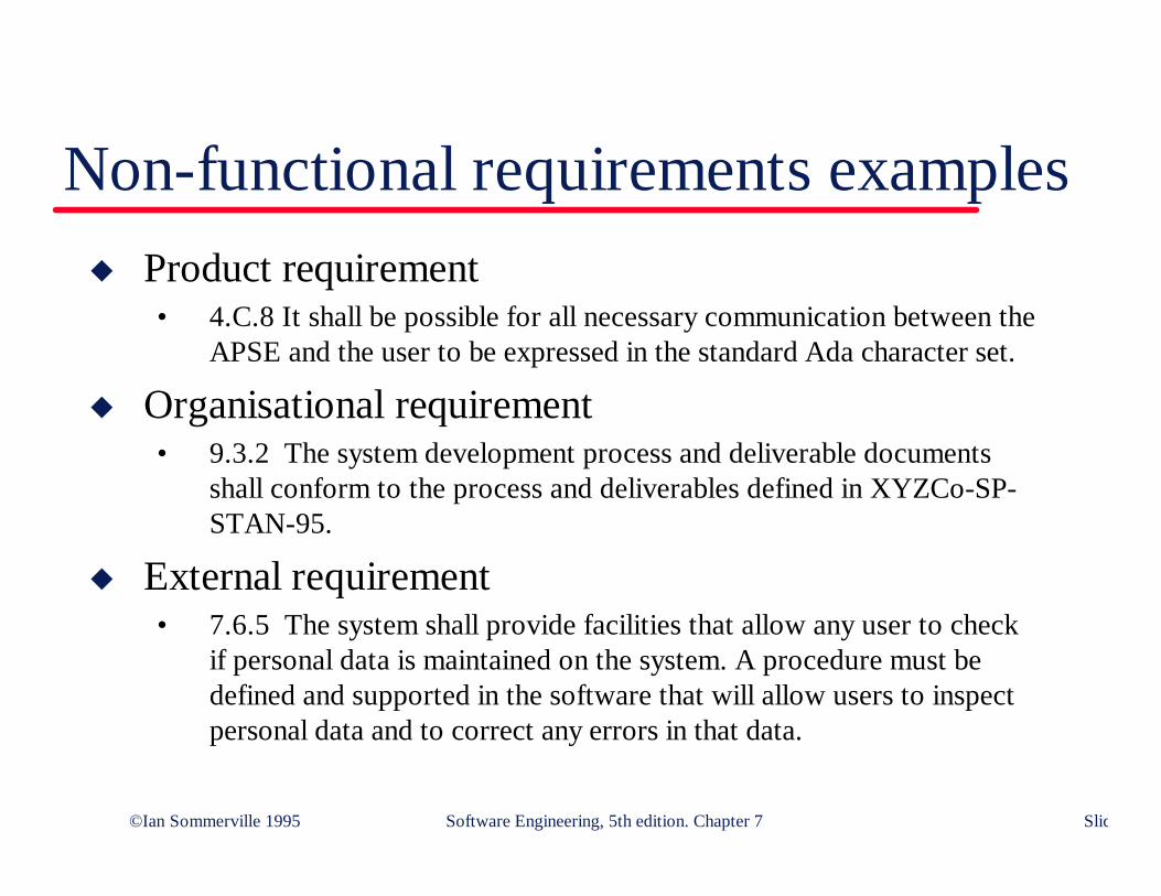
Non-functional requirements examplesu Product requirement
• 4.C.8 It shall be possible for all necessary communication between theAPSE and the user to be expressed in the standard Ada character set.
u Organisational requirement• 9.3.2 The system development process and deliverable documents
shall conform to the process and deliverables defined in XYZCo-SP-STAN-95.
u External requirement• 7.6.5 The system shall provide facilities that allow any user to check
if personal data is maintained on the system. A procedure must bedefined and supported in the software that will allow users to inspectpersonal data and to correct any errors in that data.
©Ian Sommerville 1995 Software Engineering, 5th edition. Chapter 7 Slide
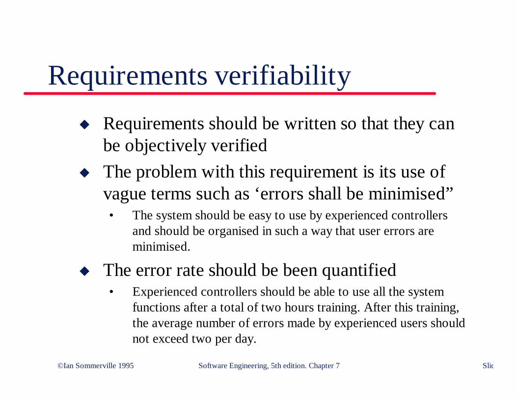
Requirements verifiabilityu Requirements should be written so that they can
be objectively verifiedu The problem with this requirement is its use of
vague terms such as ‘errors shall be minimised”• The system should be easy to use by experienced controllers
and should be organised in such a way that user errors areminimised.
u The error rate should be been quantified• Experienced controllers should be able to use all the system
functions after a total of two hours training. After this training,the average number of errors made by experienced users shouldnot exceed two per day.
©Ian Sommerville 1995 Software Engineering, 5th edition. Chapter 7 Slide
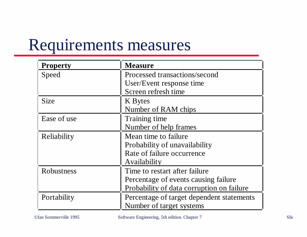
Requirements measuresProperty MeasureSpeed Processed transactions/second
User/Event response timeScreen refresh time
Size K BytesNumber of RAM chips
Ease of use Training timeNumber of help frames
Reliability Mean time to failureProbability of unavailabilityRate of failure occurrenceAvailability
Robustness Time to restart after failurePercentage of events causing failureProbability of data corruption on failure
Portability Percentage of target dependent statementsNumber of target systems

©Ian Sommerville 1995 Software Engineering, 5th edition. Chapter 7 Slide
Requirements separationu Functional and non-functional requirements
should, in principle, be distinguished in arequirements specification
u However, this is difficult as requirements may beexpressed as whole system requirements ratherthan constraints on individual functions
u It is sometimes difficult to decide if a requirementis functional or a non-functional• For example, requirements for safety are concerned with non-
functional properties but may require functions to be added tothe system

©Ian Sommerville 1995 Software Engineering, 5th edition. Chapter 7 Slide
System-level requirementsu Some requirements place constraints on the
system as a whole rather than specific systemfunctions
u Example• The time required for training a system operator to be proficient
in the use of the system must not exceed 2 working days.
u These may be emergent requirements (seeChapter 2) which cannot be derived from anysingle sub-set of the system requirements
©Ian Sommerville 1995 Software Engineering, 5th edition. Chapter 7 Slide
Key pointsu A requirements definition is used by customers
and end-users. It must be written in a languagewhich they can understand
u Rationale for a requirement should always beincluded in a requirements definition
u Requirements should be written so that they maybe verified

©Ian Sommerville 1995 Software Engineering, 5th edition. Chapter 7 Slide
Key pointsu Requirements specifications are intended to
precisely communicate the system functions andconstraints. They may be written in some form ofstructured language
u Three classes of non-functional requirement areproduct requirements, process requirements andexternal requirements
u Natural language is normally used to write non-functional requirements because of theirvariability and complexity