requirements for fire testing of fixed gaseous fire ... · requirements for fire testing of fixed...
TRANSCRIPT

© BRE Global Ltd., 2014
Loss Prevention Standard
LPS 1230: Issue 1.2
Requirements for fire testing of fixed gaseous fire extinguishing systems
This Loss Prevention Standard is the property of BRE Global Ltd. and is made publicly available for information purposes only. Its use for testing, assessment, certification or approval must be in accordance with LPCB internal procedures and requires interpretation by BRE Global Ltd, LPCB and BRE experts. Any party wishing to use or reproduce this Loss Prevention Standard to offer testing, assessment, certification or approval must apply to BRE Global for training, assessment and a licence; a fee will normally be charged. BRE Global Ltd. will not unreasonably refuse such applications. BRE Global Ltd. accepts no responsibility for any un-authorised use or distribution by others of this Loss Prevention Standard and may take legal action to prevent such unauthorised use or distribution

© BRE Global Ltd., 2014

Issue 1.2 LOSS PREVENTION STANDARD LPS 1230
Date: Jan. 2014 Requirements for fire testing of fixed gaseous fire extinguishing systems Page 1 of 24
© BRE Global Ltd., 2014
CONTENTS PAGE
REVISION OF LOSS PREVENTION STANDARDS 3 FOREWORD 4 SAFETY 4 1. SCOPE 5 2. METHODOLOGY 5 3. DEFINITIONS 6
3.1 System 6 3.2 System provider or firm 6 3.3 Gas supplier 6 3.4 Inert agent 6 3.5 Halocarbon agent 6 3.6 Concentrations 6
3.6.1 Extinguishing concentration 6 3.6.2 Minimum design concentration 7 3.6.3 Design concentration 7
3.7 Cold discharge test 7 3.8 Discharge times 7
3.8.1 Halocarbon agent discharge time 7 3.8.2 Inert agent discharge time 7
3.9 Fire classification 7 3.9.1 Class A fire/risk 7 3.9.2 Class A wood fire 7 3.9.3 Polymeric Class A fire 7 3.9.4 Class B fire/risk 7
3.10 Baffled fire 7 3.11 Pressure relief system 7
4. SYSTEM SPECIFICATION 8
4.1 Extinguishing agent details 8 4.2 System details 8
5. REQUIREMENTS 8
5.1 System design and installation 8 5.2 System requirements 9 5.3 Operational requirements 9
6. GASEOUS EXTINGUISHING SYSTEM TEST FIRES AND PROCEDURE 10
6.1 The test enclosure 10 6.1.1 Geometry and construction details of multiple volume “cold discharge” test
enclosure 10 6.1.2 Geometry and construction details of fire test enclosure 10 6.1.3 Instrumentation details 12

Issue 1.2 LOSS PREVENTION STANDARD LPS 1230
Date: Jan. 2014 Requirements for fire testing of fixed gaseous fire extinguishing systems Page 2 of 24
© BRE Global Ltd., 2014
6.1.3.1 Data collection 12 6.1.3.2 Temperature measurement 12 6.1.3.3 Pressure measurement 12 6.1.3.4 Gas measurement 13 6.1.3.5 Fuel mass measurement 13 6.1.3.6 Obscuration † 13 6.1.3.7 Video 14
6.1.4 Pre-test conditioning 14 6.1.5 Fire pre-burn ventilation 14 6.1.6 Fire baffle specification 14
6.2 Cold discharge tests 16 6.2.1 Multiple volume cold discharge test 16 6.2.2 Cold discharge test in fire enclosure 16
6.3 Class A fire test 16 6.4 Polymeric Class A fire test 19
7. Requirement summary 22 Table of amendments issued since publication 24

Issue 1.2 LOSS PREVENTION STANDARD LPS 1230
Date: Jan. 2014 Requirements for fire testing of fixed gaseous fire extinguishing systems Page 3 of 24
© BRE Global Ltd., 2014
REVISION OF LOSS PREVENTION STANDARDS Loss Prevention Standards will be revised by issue of revised editions or amendments. Details will be posted on our website at www.redbooklive.com Technical or other changes which affect the requirements for the approval or certification of the product or service will result in a new issue. Minor or administrative changes (e.g. corrections of spelling and typographical errors, changes to address and copyright details, the addition of notes for clarification etc.) may be made as amendments. (See amendments table on page 24) The issue number will be given in decimal format with the integer part giving the issue number and the fractional part giving the number of amendments (e.g. Issue 3.2 indicates that the document is at Issue 3 with 2 amendments). USERS OF LOSS PREVENTION STANDARDS SHOULD ENSURE THAT THEY POSSESS THE LATEST ISSUE AND ALL AMENDMENTS.

Issue 1.2 LOSS PREVENTION STANDARD LPS 1230
Date: Jan. 2014 Requirements for fire testing of fixed gaseous fire extinguishing systems Page 4 of 24
© BRE Global Ltd., 2014
FOREWORD For LPCB Approval, the Loss Prevention Standard should be read in conjunction with LPCB Approval Scheme Document SD022: Gaseous Fire Fighting Components and Systems This Scheme has been prepared and approved by Technical Panel B of the Loss Prevention Certification Board, which includes representatives from the following organisations:
• Association of British Insurers. • British Fire Protection Systems Association Ltd. • Confederation of British Industry. • Chief and Assistant Chief Fire Officers Association. Applications for approval and further information may be obtained from:-
Customer Services LPCB Garston Watford Herts WD25 9XX Tel: 01923 664100 Fax: 01923 664603
NOTES Compliance with this LPS does not of itself confer immunity from legal obligations. Users of LPSs should ensure that they possess the latest issue and all amendments. LPCB welcomes comments of a technical or editorial nature and these should be addressed to “the Technical Director” at [email protected]. The BRE Trust, a registered charity, owns BRE and BRE Global. BRE Global and LPCB (part of BRE Global) test, assess, certificate and list products and services within the fire and security sectors. For further information on our services please contact BRE Global, Watford, Herts. WD25 9XX or e-mail to [email protected] Listed products and services appear in the LPCB “List of Approved Products and Services” which may be viewed on our website: www.redbooklive.com or by downloading the LPCB Red Book App from the App Store (for iPhone and iPad), from Google Play (for Android devices) or from the Windows Store (for Windows 8 Phones and Tablets from 2014).
SAFETY Gases used for extinguishing fires are generally hazardous to health. A rigorous risk assessment based on the latest health and safety data sheets should be completed prior to undertaking any tests in this document.

Issue 1.2 LOSS PREVENTION STANDARD LPS 1230
Date: Jan. 2014 Requirements for fire testing of fixed gaseous fire extinguishing systems Page 5 of 24
© BRE Global Ltd., 2014
SCOPE 1This document stipulates the test requirements for fire testing of fixed gaseous fire extinguishing systems (Part 7 : Sections 2.1 and 2.3). LPS 1230 is appropriate for the evaluation of extinguishing system performance of Halon Alternative fixed extinguishing systems, of the non-liquefied inert and halocarbon gas types. Suitability for the evaluation of other gaseous extinguishing technologies will be considered on an individual basis. Parts of the test protocol described herein are common to the testing requirements of ISO 14520-1 “Gaseous fire extinguishing systems – Physical properties and system design – Part 1” – ANNEX C, and so conformity to ISO 14520-1 is implicit in the satisfactory completion of LPS 1230.
A firm’s fixed gaseous fire extinguishing system shall satisfy the requirements of this specification using concentrations that are not greater than the minimum design concentrations specified in the firm’s Design Manual1 appropriate to a given class of risk.
None of the tests presented herein for the evaluation of the performance of fixed gaseous systems are considered ‘special hazards’ (manageable by a correctly designed Halon 1301 system). To this end the use of agent concentrations appropriate to ‘special’ hazards (as defined in the system provider’s design manual) is not permitted.
METHODOLOGY 2This approval uses the ISO test regime ("Gaseous fire extinguishing systems – Physical properties and system design – Part 1 – Annex C") for the evaluation of agent extinguishing concentrations and nozzle performance, see 2(a).
Specific tests are conducted at the minimum design concentrations. The minimum design concentrations chosen by the system provider may include additional safety factors on this value to accommodate circumstances specific to the risk, see 2(b).
Operational details and requirements of the ISO tests are confined to Appendix A of this document.
The methodology of the overall test regime is as follows:
a) ISO fire test regime determines the extinguishing concentrations of agent on Class A (wood and plastic fuels), and Class B (heptane) fire types
b) LPS 1230 test regime establishes the performance of agent at the anticipated approved minimum design concentration (generally taken as being the extinguishing concentration + 30 %) on fires of a more complex and realistic configuration and checks the suitability of the delivery system and supporting design calculations by:
(i) Evaluation of the hydraulic design calculation during simultaneous ‘cold discharge’ of agent into multiple enclosures of different volumes
(ii) Evaluation of the hydraulic design and pressure relief calculations during ‘cold discharge’ of agent into the fire test enclosure using the minimum design concentration for Class A risks
1 It is the firm’s responsibility to ensure that the design concentration includes additional safety factors where appropriate.
Issue 1.2 LOSS PREVENTION STANDARD LPS 1230
Date: Jan. 2014 Requirements for fire testing of fixed gaseous fire extinguishing systems Page 6 of 24
© BRE Global Ltd., 2014
(iii) Evaluation of the hydraulic design and pressure relief calculations during ‘cold discharge’ of agent into the fire test enclosure using the minimum design concentration for Class B risks
(iv) Confirmation of Class A minimum design concentration on a cellulostic fuel fire
(v) Confirmation of Class A minimum design concentration on a polymeric fuel fire
(vi) Confirmation of Class B minimum design concentration on a liquid fuel fire
c) The minimum design concentration for Electronic Data Processing (EDP) rooms, control rooms, computer suites etc. shall be determined by satisfactory extinguishment of the Class A wood and Class A Polymeric fires at the same single concentration.
d) The minimum design concentration for flammable fuel hazards shall be determined by satisfactory extinguishment of the Class B fires at a single concentration that may be different to that used in c).
DEFINITIONS 3 System 3.1
‘System’ is a fixed gaseous fire extinguishing system, comprising nozzles, pipe work, fixings, control valves, pressure vessels, the appropriate fire extinguishing agent and any essential fixtures to the test enclosure such as a pressure relief vent.
System provider or firm 3.2‘System Provider’ or ‘firm’ denotes a company or organisation commercially and technically responsible for the correct supply and commissioning of the installed system.
Gas supplier 3.3‘Gas supplier’ denotes a company or organisation that supplies extinguishing agent to the system provider.
Inert agent 3.4‘Inert agent’ is a generic term used to identify non-liquefied extinguishing agents whose principle method of operation is by reducing the oxygen concentration of the atmosphere local to the fire below a level that can support combustion.
Halocarbon agent 3.5‘Halocarbon agent’ is a generic term used to identify extinguishing agents comprising chemical substances whose principle method of operation is by removing heat from the fire and interfering with the chemistry of the combustion process.
Concentrations 3.6 Extinguishing concentration 3.6.1
Minimum concentration of extinguishing agent required to extinguish the flame of a particular fuel under experimental conditions excluding a safety factor.

Issue 1.2 LOSS PREVENTION STANDARD LPS 1230
Date: Jan. 2014 Requirements for fire testing of fixed gaseous fire extinguishing systems Page 7 of 24
© BRE Global Ltd., 2014
Minimum design concentration 3.6.2This is the concentration selected by the firm to satisfy the requirements of LPS 1230 (generally = extinguishing concentration plus 30%). System designs using concentrations less than this value are not approved.
Design concentration 3.6.3‘Design concentration’ is the amount of agent including an additional safety factor on the minimum design concentration where appropriate, required for system design purposes.
Cold discharge test 3.7Cold discharge test’ refers to a test in which the agent is released into the enclosure without a fire set.
Discharge times 3.8 Halocarbon agent discharge time 3.8.1
The ‘halocarbon agent discharge time’ shall be taken as the time between the peaks of the two ‘humps’ characteristic of the pipeline pressure profile measured by a pressure transducer located close to the nozzle.
Inert agent discharge time 3.8.2The ‘inert agent discharge time’ shall be taken as the time for 95% of the agent to be discharged as determined by measurement of the oxygen depletion in the enclosure.
Fire classification 3.9 Class A fire/risk 3.9.1
‘Class A fire’ refers to a fire fuelled by a solid fuel source such as wood or plastic.
Class A wood fire 3.9.2‘Class A wood fire’ refers to a fire comprised of a wood fuel source.
Polymeric Class A fire 3.9.3‘Polymeric Class A fire’ refers to a fire fuelled by a plastic material such as polypropylene or PVC.
Class B fire/risk 3.9.4‘Class B fire’ refers to a fire fuelled by a flammable liquid such as heptane.
Baffled fire 3.10‘Baffled fire’ denotes a fire around which an obstruction has been placed to limit direct access to the fire.
Pressure relief system 3.11‘Pressure relief system’ denotes an orifice(s) or ‘device(s)’ installed in the wall of the enclosure designed to mitigate pressure fluctuations within the enclosure to acceptable limits during discharge of the agent, whilst maintaining a satisfactory hold-time thereafter.

Issue 1.2 LOSS PREVENTION STANDARD LPS 1230
Date: Jan. 2014 Requirements for fire testing of fixed gaseous fire extinguishing systems Page 8 of 24
© BRE Global Ltd., 2014
SYSTEM SPECIFICATION 4 Extinguishing agent details 4.1
The system provider shall supply the following information:
(a) Agent name (commercial and chemical).
(b) Blend details and apportionment.
(c) Analysis of agent taken from ‘stock batch’ from which the system containers were filled.
(d) Material Safety Data Sheet for agent.
System details 4.2The system provider shall supply copies of the calculations used to establish:
(a) The two design concentrations that will extinguish the Class A and Class B test fires respectively (if they are different).
(b) Mass of agent in cylinder(s) required to achieve the design concentrations within the specified enclosure(s) 2 3 for the Cold discharges, Class A and Class B fire tests.
(c) Agent discharge times for the Cold discharges, Class A and Class B fire tests.
(d) Design details of the pressure relief system requirements to maintain the enclosure pressures within acceptable limits 4, whilst maintaining a satisfactory ‘hold-time’ of agent at an appropriate concentration5 for all the cold discharges (3 off: Multiple volume; Class A concentration; and Class B concentration).
(e) System installation details including pipe work plan, dimensions and nozzle specification for the Cold discharges, Class A and Class B fire tests.
REQUIREMENTS 5The firm’s gaseous fire extinguishing system, when designed and installed as detailed below, shall extinguish all the test fires in accordance with this standard, at the first attempt.
System design and installation 5.1Three system designs would normally be required for the fulfilment of the LPS 1230 test regime:
(i) Design for the evaluation of the hydraulic calculation which discharges into multiple enclosures of different volumes
(ii) Design for tackling the Class A fires at the minimum design concentration
(iii) Design for tackling the Class B fires at the minimum design concentration
2 Defined in Section 6 3 Where a propelling gas is used (such as nitrogen) the mass of this shall also be stated. 4 Defined in Section 5. 5 Defined in Section 5.
Issue 1.2 LOSS PREVENTION STANDARD LPS 1230
Date: Jan. 2014 Requirements for fire testing of fixed gaseous fire extinguishing systems Page 9 of 24
© BRE Global Ltd., 2014
The systems shall be designed in accordance with the design manual, to provide total flooding protection of the enclosure(s) described in Section 6.1, without jeopardising the integrity of the enclosure(s) 6.
The system design and installation specification of the installed systems will be inspected for conformance with the design and installation specification submitted. Systems not installed in accordance with the submitted specification shall not be tested.
Installation of the system shall be performed by the firm or an authorised LPS 1204 installer. The system shall conform to the design manual and remain unchanged for the duration of each Class of fire.
The system design shall incorporate the minimum number of nozzles permitted by the design manual.
System requirements 5.2(a) Comparison of the analysis of the agent contained in the system with data obtained
from the gas supplier shall confirm it to be that specified in the design manual.
(b) The system shall be installed in accordance with the firm’s design manual.
(c) Modification of the enclosure to accept the extinguishing system will be made by the firm or authorised LPS 1204 installer and be supported by appropriate design calculations.
(d) The agent discharge shall not be directed at the fire source.
Operational requirements 5.3(a) During ‘cold discharge’ into multiple enclosures, the same single calculated
concentration shall be achieved in each of the enclosures (-5+10% of required concentration)
(b) During cold discharge into the fire enclosure with Class A and Class B minimum design concentrations:
(i) The calculated concentration shall be achieved (-5+10% of required concentration)
(ii) The pressures within the enclosure shall be mitigated to within 6300 Pa by the installed pressure relief device
(iii) The concentration of agent at 1/5 and 4/5 of the enclosure height shall be >= the extinguishing concentration 10 minutes after the end of agent discharge
(iv) The discharge time of the agent shall be within 20% of the stated value
(c) All Class A fires shall be extinguished (no flaming) within 180 seconds of the start of agent discharge at the first attempt
(d) All Class B fires shall be extinguished (no flaming) within 90 seconds of the end of agent discharge at the first attempt
6 The firm shall specify a concentration for each of the two Classes of fire for the system, which should not be greater than the design concentration specified in the Design Manual. This concentration shall be regarded by the LPCB not to contain a safety factor.

Issue 1.2 LOSS PREVENTION STANDARD LPS 1230
Date: Jan. 2014 Requirements for fire testing of fixed gaseous fire extinguishing systems Page 10 of 24
© BRE Global Ltd., 2014
(e) There shall be no re-ignition of any fire for a period of ten minutes after the end of agent discharge
(f) The discharge time of the agent for all fire tests shall be within 20% of the stated value for each fire type
(g) Significant deviation of other design parameters observed during tests shall be reported and investigated
(h) Instances of malfunction of system parts during tests shall be reported and investigated.
GASEOUS EXTINGUISHING SYSTEM TEST FIRES AND PROCEDURE 6The configuration and operational procedures defined herein for the test fires are designed to produce highly repeatable fires that are suitable for the evaluation of extinguishing system performance of Halon alternative fixed gaseous fire extinguishing systems.
Two fuel types are used in the evaluation covering Class A (using wood and plastic fuels), and Class B risks. Three ‘cold discharge’ tests are required for the evaluation of some operational parameters making a total of six tests.
The test enclosure 6.1 Geometry and construction details of multiple volume “cold discharge” test 6.1.1
enclosure Evaluation of the hydraulic design calculations shall require simultaneous discharge of agent into multiple enclosures of different volumes. The fire test enclosure defined in Section 6.1.2 shall be subdivided with partition walls to form 3 separate compartments with specified volumes7.
Geometry and construction details of fire test enclosure 6.1.2The enclosure shall have nominal internal floor dimensions of 8 metres long by 4 metres wide. The roof height is chosen to suit the discharge nozzle but is not to be less than 3.5 metres high (all dimensions ±0.1 metres). The construction of the enclosure shall be such that none of the internal surfaces shall flex in reaction to pressure excursions upon agent discharge 8. Where sheet materials must be used, i.e. calcium silicate board on the ceiling, it shall be supported in such a way as to discourage movement.
Access to the enclosure is to be via a door (see Figure 1) and windows set in two adjacent walls will allow viewing of the fire. The door is to be constructed so as to provide a suitable location for the positioning of the extinguishing system’s pressure relief vent(s), although, if this position is considered unsuitable other reasonable locations may be used.
Ventilation of the enclosure during the fire pre-burn period is provided by an inlet situated under the fire load cell platform and outlet located high in the east wall. Both extract ducts are fitted with adjustable speed fans and shut off dampers.
7 Alternatives to discharging into separate enclosures such as agent collection methods may be acceptable. 8 The use of high-density concrete block is preferred.

Issue 1.2 LOSS PREVENTION STANDARD LPS 1230
Date: Jan. 2014 Requirements for fire testing of fixed gaseous fire extinguishing systems Page 11 of 24
© BRE Global Ltd., 2014
With the door and ventilation dampers closed the entire room will be well sealed (no measurable leakage by the standard ‘room fan test’).
Facilities shall be in place to remotely ignite the fires.
Figure 1 – Test enclosure geometry and instrument locations – plan and side elevation
8000mm
to s
uit n
ozzle
>= 3
500
mm
4000
mm
Enclosure pressuretransducer
1150
mm
Load cellplatform
1/5
h
200m
m
1150
mm
Inletduct
2000mm
Inlet ductdamper
700mm
Inlet airbaffle
1000mm
Gas samplingpoint
Plume thermocouplearray
Extractduct
4/5
h
Agent samplingpoints at 1/5 and 4/5
of the roof height
Load cellplatform
Extract ductdamper
500m
m
Extractduct fan
Remote thermocouplearray
1000mm
Plume thermocouplearray
Gas samplingpoint
1000
mm
Enclosure pressuretransduer
1000
mm
600m
m
Remote thermocoupletree
Inletduct fan
Extractduct
Inletduct
Issue 1.2 LOSS PREVENTION STANDARD LPS 1230
Date: Jan. 2014 Requirements for fire testing of fixed gaseous fire extinguishing systems Page 12 of 24
© BRE Global Ltd., 2014
Instrumentation details 6.1.3The instrumentation described below is intended to:
• Verify the reproducibility of the fires on which the systems are tested.
• Collect information on the characteristics of agent discharge.
• Collect information on the effect of agent on the fire.
• Collect information on the effect of agent discharge on the temperature and pressure in the enclosure.
• Collect information on the by-products of fire and agent breakdown products.
Some of the instrumentation described is not required for the approval process, providing details of other factors related to the use of gaseous extinguishing systems. Extraneous instrumentation and measurements are marked as optional as they occur in the following text9.
6.1.3.1 Data collection Data from the prescribed sensors are to be logged at a rate of not less than 2 Hz. Where particularly fast events occur this may need to be increased.
6.1.3.2 Temperature measurement Thermocouples shall be installed in the enclosure as follows:
Plume thermocouple tree
A vertical array of six K-type thermocouples spaced 0.5 metres apart shall span from the ceiling to 0.5 metres above the floor. The array shall be positioned such that the tips of the thermocouples are located centrally above fire. The positioning of the lower thermocouples is not to interfere with the operation of the fire load cell platform. The top thermocouple shall be in contact with the ceiling.
Remote thermocouple tree
A vertical array of seven K-type thermocouples spaced 0.5 metres apart shall span from the ceiling to the floor of the enclosure. The array shall be positioned such that the tips of the thermocouples are located as shown in Figure 1. The top and bottom thermocouples shall be in contact with the ceiling and floor surfaces respectively.
Nozzle temperature measurement
A fast response thermocouple shall be located close to the discharge nozzle to monitor agent discharge details.
6.1.3.3 Pressure measurement Agent discharge pressure
A fast response pressure transducer shall be located in the system’s discharge pipe-work at a location close to the nozzle on a T fitting. The pressure transducer shall be sized appropriately to have a range from zero bar to a value in excess of the agent’s storage pressure. An event recording rate of not less than 20 Hz shall be used.
9 Use of optional equipment may increase test programme costs.

Issue 1.2 LOSS PREVENTION STANDARD LPS 1230
Date: Jan. 2014 Requirements for fire testing of fixed gaseous fire extinguishing systems Page 13 of 24
© BRE Global Ltd., 2014
Enclosure pressure
A differential pressure transducer having a range of ±2000 Pascals shall be installed as shown in Figure 1. An event recording rate of not less than 20 Hz shall be used.
6.1.3.4 Gas measurement The gaseous contents of the enclosure are to be sampled as shown in Figure 1. The extract rate is to be such that the sampling delay is less than 5 seconds. The instrumentation is to have the following properties.
Oxygen
The analyser is to be capable of measuring oxygen in the range of 0 to 25 % to a nominal accuracy of ±0.1 %. Analysers of the paramagnetic type have proved appropriate.
Carbon dioxide †
Analysers of the infrared type have proved appropriate although some extinguishing agents interfere with their operation.
Carbon monoxide †
Analysers of the infrared type have proved appropriate although some extinguishing agents interfere with their operation. Acid gas measurement †
Some extinguishing agents have the potential to break down in the fire forming acidic by-products. These compounds are generally water-soluble and so may be collected by an appropriate gas absorption technique.
Agent
Agent concentrations shall be continually monitored using the most appropriate real time system for the agent. Agent concentrations during the discharge of inert gas systems may be determined from the detected oxygen depletion. Specialist instrumentation is required for the determination of halocarbon agent concentrations. Sampling points shall be located at 1/5th and 4/5th of the room height as shown in Figure 1 for single compartment ‘cold-discharge’ tests. Multiple volume discharge tests shall sample the agent from a single point within each enclosure at a height of 1150mm from the floor.
All analysers are to be calibrated prior to each test between zero and an upper value in keeping with likely detected concentrations.
6.1.3.5 Fuel mass measurement The primary fire shall be located upon a load cell platform that is protected from the inlet airflow. The load cell is to be calibrated to an accuracy of 0.001 kg prior to each test. A range of 0 to 30 kg has proved suitable for the listed fires.
6.1.3.6 Obscuration † An obscuration meter shall be positioned across the width of the enclosure as shown in Figure 1 at a height of 1150 mm from the floor to determine the fogging characteristics of the agent.
† Optional – Measurements that may be made if requested by the firm, but form no part of the Approval.
Issue 1.2 LOSS PREVENTION STANDARD LPS 1230
Date: Jan. 2014 Requirements for fire testing of fixed gaseous fire extinguishing systems Page 14 of 24
© BRE Global Ltd., 2014
6.1.3.7 Video A camera connected to a VCR positioned at the window in the longest wall, directed at the fire, shall record the proceedings of each experimental test.
Pre-test conditioning 6.1.4Prior to testing, the enclosure shall be conditioned to the following parameters:
• Enclosure air temperature 15- 22 oC
• Relative humidity 40 – 60 % RH
• Extinguisher container temperature 18 – 22 oC
Fire pre-burn ventilation 6.1.5During the pre-burn period the fire is force vented to maintain oxygen levels within the enclosure. The ventilation is stopped and associated duct systems closed prior to agent discharge.
The fans in the inlet and outlet duct shall be set to provide an outflow to be determined by test (* m3s-1) whilst maintaining a pressure within the enclosure of 50 Pascals (measured in the absence of pressure relief systems).
Fire baffle specification 6.1.6Details of the geometry of the baffle system are shown in Figure 2. Each fire is partially shielded by two boxes (1 m x 1 m x 0.5 m) which are open top and bottom, and a top covering plate. The bottom baffle box and top baffle plate are offset by 45o from the top baffle box creating 8 triangular voids for the passage of gas to the fire. The bottom baffle box is raised creating four additional flow paths around the base of the fire as shown in Figure 2.
The baffle boxes shall be constructed of 2mm stainless steel. The bottom baffle box shall incorporate a viewing window in one side of appropriately fire-resisting glazing. The top baffle plate shall be constructed of a single sheet of 12 mm calcium silicate board. All parts of the fire baffle shall be secured in place to stop movement during gas discharge.

Issue 1.2 LOSS PREVENTION STANDARD LPS 1230
Date: Jan. 2014 Requirements for fire testing of fixed gaseous fire extinguishing systems Page 15 of 24
© BRE Global Ltd., 2014
Figure 2 – Shield configuration for baffled fire tests
1000
mm
Load c el l p la tform
B ottom baffle box
W ired glas sv iewing window
B affle s upportb loc k
Top baffle box
Top baffle p la te
1000 m m
500
mm
500
mm
100
mm

Issue 1.2 LOSS PREVENTION STANDARD LPS 1230
Date: Jan. 2014 Requirements for fire testing of fixed gaseous fire extinguishing systems Page 16 of 24
© BRE Global Ltd., 2014
Cold discharge tests 6.2 Multiple volume cold discharge test 6.2.1
Prior to commencing fire testing the suitability of the hydraulic design calculation shall be established by simultaneous discharge of agent into 3 enclosures of different volumes.
Each enclosure shall be sealed except for the pressure relief system installed by the system provider.
The test will establish whether the design calculation and associated equipment can deliver the same single agent concentration to each of the three enclosures.
Cold discharge test in fire enclosure 6.2.2Prior to testing the system on the design fires, the agent shall be discharged into the preconditioned enclosure, with no fire.
The enclosure will be sealed except for the pressure relief system installed by the system provider. This test will establish:
• Agent discharge time
• Mass of agent used
• Pressure fluctuations within the enclosure
• Agent concentrations and hold-times in the absence of fire
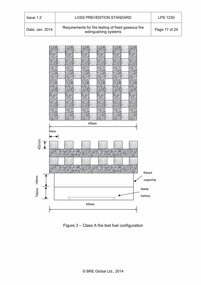
Class A fire test 6.3The configuration of the Class A fire is as shown in Figure 3 and is to be located on the load cell platform in the middle of the enclosure inside the baffle (see 6.1.6).
Issue 1.2 LOSS PREVENTION STANDARD LPS 1230
Date: Jan. 2014 Requirements for fire testing of fixed gaseous fire extinguishing systems Page 17 of 24
© BRE Global Ltd., 2014
Figure 3 – Class A fire test fuel configuration
Issue 1.2 LOSS PREVENTION STANDARD LPS 1230
Date: Jan. 2014 Requirements for fire testing of fixed gaseous fire extinguishing systems Page 18 of 24
© BRE Global Ltd., 2014
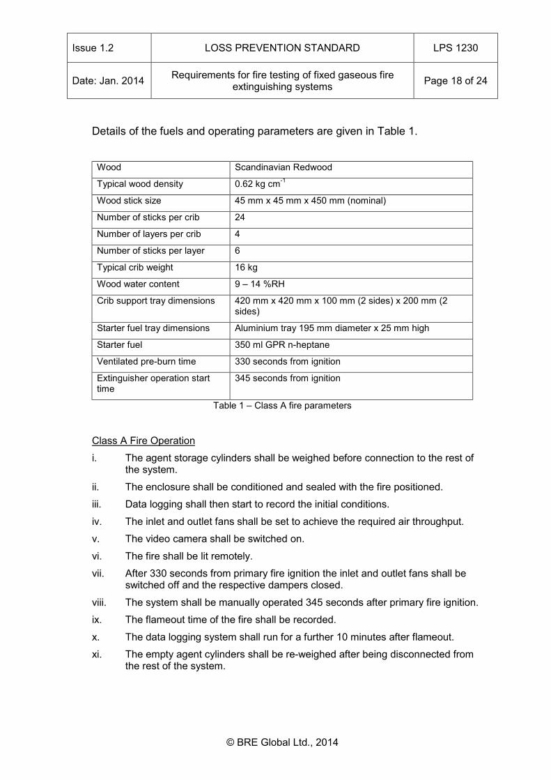
Details of the fuels and operating parameters are given in Table 1. Wood Scandinavian Redwood
Typical wood density 0.62 kg cm-1
Wood stick size 45 mm x 45 mm x 450 mm (nominal)
Number of sticks per crib 24
Number of layers per crib 4
Number of sticks per layer 6
Typical crib weight 16 kg
Wood water content 9 – 14 %RH
Crib support tray dimensions 420 mm x 420 mm x 100 mm (2 sides) x 200 mm (2 sides)
Starter fuel tray dimensions Aluminium tray 195 mm diameter x 25 mm high
Starter fuel 350 ml GPR n-heptane
Ventilated pre-burn time 330 seconds from ignition
Extinguisher operation start time
345 seconds from ignition
Table 1 – Class A fire parameters
Class A Fire Operation
i. The agent storage cylinders shall be weighed before connection to the rest of the system.
ii. The enclosure shall be conditioned and sealed with the fire positioned.
iii. Data logging shall then start to record the initial conditions.
iv. The inlet and outlet fans shall be set to achieve the required air throughput.
v. The video camera shall be switched on.
vi. The fire shall be lit remotely.
vii. After 330 seconds from primary fire ignition the inlet and outlet fans shall be switched off and the respective dampers closed.
viii. The system shall be manually operated 345 seconds after primary fire ignition.
ix. The flameout time of the fire shall be recorded.
x. The data logging system shall run for a further 10 minutes after flameout.
xi. The empty agent cylinders shall be re-weighed after being disconnected from the rest of the system.
Issue 1.2 LOSS PREVENTION STANDARD LPS 1230
Date: Jan. 2014 Requirements for fire testing of fixed gaseous fire extinguishing systems Page 19 of 24
© BRE Global Ltd., 2014
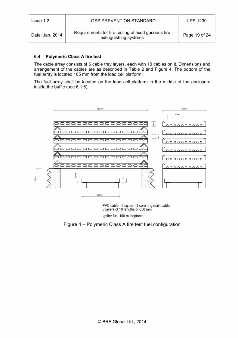
Polymeric Class A fire test 6.4The cable array consists of 6 cable tray layers, each with 10 cables on it. Dimensions and arrangement of the cables are as described in Table 2 and Figure 4. The bottom of the fuel array is located 105 mm from the load cell platform.
The fuel array shall be located on the load cell platform in the middle of the enclosure inside the baffle (see 6.1.6).
Figure 4 – Polymeric Class A fire test fuel configuration
750 mm
PVC cable - 6 sq. mm 3 core ring main cable6 layers of 10 lengths of 650 mm
Igniter fuel 100 ml heptane
100m
m 75m
m
200mm
20m
m
230mm
20m
m
20mm
25m
m

Issue 1.2 LOSS PREVENTION STANDARD LPS 1230
Date: Jan. 2014 Requirements for fire testing of fixed gaseous fire extinguishing systems Page 20 of 24
© BRE Global Ltd., 2014
Test Parameter Measurement
Cable PVC “Ring main” cable – non fire retarded
Cable tray length 750mm
Cable tray width 230 mm
Cable length 650mm
Number of cables per layer 10
Cable separation (distance between centres)
20 mm
Cable tray porosity 20.3%
Cable tray separation 20mm
Starter fuel (n-heptane) quantity 100ml
Height of fire above base of starter fuel tray
75mm
Ventilated pre-burn time TBA (awaiting ISO note)
Extinguisher operation start time TBA (awaiting ISO note) Table 2 - Specification of the PVC cable tray fire
Polymeric Class A Fire Operation
i. The agent storage cylinders shall be weighed before connection to the rest of the system.
ii. The enclosure shall be conditioned and sealed with the fire positioned.
iii. Data logging shall then start to record the initial conditions.
iv. The inlet and outlet fans shall be set to achieve the required air throughput.
v. The video camera shall be switched on.
vi. The fire shall be lit remotely.
vii. After *** seconds from primary fire ignition the inlet and outlet fans shall be switched off and the respective dampers closed.
viii. The system shall be manually operated *** seconds after primary fire ignition.
ix. The flameout time of the fire shall be recorded.
x. The data logging system shall run for a further 10 minutes after flameout.
xi. The empty agent cylinders shall be re-weighed after being disconnected from the rest of the system.
***to be determined by test
Issue 1.2 LOSS PREVENTION STANDARD LPS 1230
Date: Jan. 2014 Requirements for fire testing of fixed gaseous fire extinguishing systems Page 21 of 24
© BRE Global Ltd., 2014
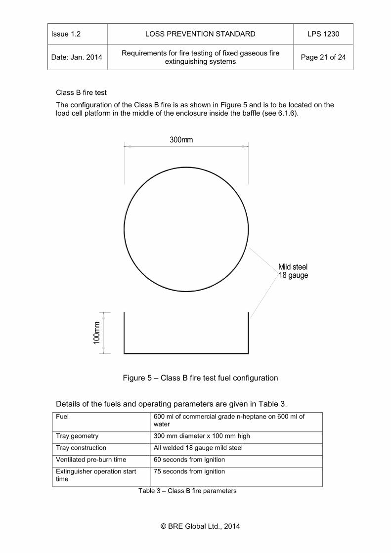
Class B fire test
The configuration of the Class B fire is as shown in Figure 5 and is to be located on the load cell platform in the middle of the enclosure inside the baffle (see 6.1.6).
Figure 5 – Class B fire test fuel configuration
Details of the fuels and operating parameters are given in Table 3. Fuel 600 ml of commercial grade n-heptane on 600 ml of
water
Tray geometry 300 mm diameter x 100 mm high
Tray construction All welded 18 gauge mild steel
Ventilated pre-burn time 60 seconds from ignition
Extinguisher operation start time
75 seconds from ignition
Table 3 – Class B fire parameters
100m
m
300mm
Mild steel18 gauge
Issue 1.2 LOSS PREVENTION STANDARD LPS 1230
Date: Jan. 2014 Requirements for fire testing of fixed gaseous fire extinguishing systems Page 22 of 24
© BRE Global Ltd., 2014
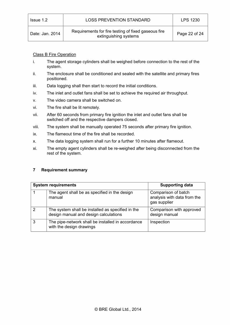
Class B Fire Operation
i. The agent storage cylinders shall be weighed before connection to the rest of the system.
ii. The enclosure shall be conditioned and sealed with the satellite and primary fires positioned.
iii. Data logging shall then start to record the initial conditions.
iv. The inlet and outlet fans shall be set to achieve the required air throughput.
v. The video camera shall be switched on.
vi. The fire shall be lit remotely.
vii. After 60 seconds from primary fire ignition the inlet and outlet fans shall be switched off and the respective dampers closed.
viii. The system shall be manually operated 75 seconds after primary fire ignition.
ix. The flameout time of the fire shall be recorded.
x. The data logging system shall run for a further 10 minutes after flameout.
xi. The empty agent cylinders shall be re-weighed after being disconnected from the rest of the system.
Requirement summary 7
System requirements Supporting data 1 The agent shall be as specified in the design
manual Comparison of batch analysis with data from the gas supplier
2 The system shall be installed as specified in the design manual and design calculations
Comparison with approved design manual
3 The pipe-network shall be installed in accordance with the design drawings
Inspection

Issue 1.2 LOSS PREVENTION STANDARD LPS 1230
Date: Jan. 2014 Requirements for fire testing of fixed gaseous fire extinguishing systems Page 23 of 24
© BRE Global Ltd., 2014
Operational requirements
4 All Class A fires shall be extinguished within 180 seconds of the start of agent discharge at the first attempt
Visual, video, temperature, mass loss
5 All Class B fires shall be extinguished within 90 seconds of the end of agent discharge at the first attempt
Visual, video, temperature, mass loss
6 No fire shall re-ignite for a period of 10 minutes after the end of agent discharge
Visual, video, temperature, mass loss
6 The concentration of agent remaining in each of the three enclosures after the multiple volume cold discharge test shall be within –5+10% of the minimum design concentration respectively
Gas analysis
7 The concentration of agent remaining in the fire enclosure after the Class A and Class B cold discharge tests shall be within –5+10% of the minimum design concentration respectively.
Gas analysis
8 The concentration of agent remaining in the fire enclosure 10 minutes after the Class A and Class B cold discharge tests shall be >= the extinguishing concentration for the respective fuel type.
Gas analysis
9 The measured agent discharge time shall be within 20 % of the calculated value
Pipe work pressure transducer
10 The pressure inside the enclosure shall not rise above + 300 Pascals at any time during cold discharge testing into the fire enclosure
Enclosure pressure transducer
11 The pressure within the enclosure shall not fall below – 300 Pascals at any time during cold discharge testing into the fire enclosure
Enclosure pressure transducer

Issue 1.2 LOSS PREVENTION STANDARD LPS 1230
Date: Jan. 2014 Requirements for fire testing of fixed gaseous fire extinguishing systems Page 24 of 24
© BRE Global Ltd., 2014
Amendments Issued Since Publication
DOCUMENT NO. AMENDMENT DETAILS SIGNATURE DATE
LPS 1230-1.0 Copyright changes CJA 30/07/02
LPS 1230-1.1 Further copyright changes CJA 20/09/05
LPS 1230-1.2
1. New front cover 2. Title added to header 3. Contents page moved to Page 1 4. Revision of Loss Prevention
Standards added on Page 3 5. Notes added on Page 4 6. Reformatting of headings 7. Repagination 8. Update to copyright information
DC Jan. 2014
This standard was prepared by the Loss Prevention Certification Board