requirements for the train protection and warning system iss 3.pdf · section description page ....
TRANSCRIPT

Railway Group Standard GE/RT8030 Issue Three Date April 2010
Requirements for the Train Protection and Warning System (TPWS)
Synopsis This document mandates the requirements for the Train Protection and Warning System (TPWS), the primary purpose of which is to minimise the consequence of a train passing a TPWS fitted signal at danger and a train overspeeding at certain other locations on Network Rail managed infrastructure. Additionally, it can be expected that TPWS will reduce the number of signals passed at danger (SPADs) at TPWS fitted signals.
Content approved by: Multifunctional Standards Committee on 18 December 2009 Authorised by RSSB on 18 February 2010
Copyright in the Railway Group Standards is owned by Rail Safety and Standards Board Limited. All rights are hereby reserved. No Railway Group Standard (in whole or in part) may be reproduced, stored in a retrieval system, or transmitted, in any form or means, without the prior written permission of Rail Safety and Standards Board Limited, or as expressly permitted by law. RSSB Members are granted copyright licence in accordance with the Constitution Agreement relating to Rail Safety and Standards Board Limited. In circumstances where Rail Safety and Standards Board Limited has granted a particular person or organisation permission to copy extracts from Railway Group Standards, Rail Safety and Standards Board Limited accepts no responsibility for, and excludes all liability in connection with, the use of such extracts, or any claims arising therefrom. This disclaimer applies to all forms of media in which extracts from Railway Group Standards may be reproduced. Published by: RSSB Block 2 Angel Square 1 Torrens Street London EC1V 1NY © Copyright 2010 Rail Safety and Standards Board Limited
Uncontrolled When Printed Document to be superseded as of 01/12/2012
To be superseded by GERT8030 Iss 4 published on 03/12/2011

Railway Group Standard
Requirements for the Train Protection and Warning System (TPWS)
GE/RT8030 Issue Three Date April 2010
Page 2 of 39 RSSB
Issue record Issue Date Comments
One August 2000 This document superseded GK/RT0090 Issue 1 April 1999
Two August 2004 Replaces issue one
Three April 2010 Replaces issue two to incorporate requirements for modification to the in-cab TPWS panel to provide information on what has caused a TPWS intervention. These new requirements are set out in the new Appendix F. Appendix G is provided for guidance on the provision of audible alerts. Minor changes have been incorporated into the existing text from issue two.
Where it has been considered necessary to draw the reader’s attention to the revisions in this issue, these have been marked by a vertical black line, with the exception of Appendices F and G, which are new sections. The document has also been converted to the latest format, which has necessitated the renumbering of clauses and, in some instances, minor alterations to headings.
Superseded documents The following Railway Group documents are superseded, either in whole or in part as indicated:
Superseded documents Sections superseded
Date when sections are superseded
GE/RT8030 Issue 2 Requirements for the Train Protection and Warning System (TPWS)
All 7 April 2012
GE/RT8030 Issue 2 ceases to be in force and is withdrawn as of 7 April 2012.
Supply The authoritative version of this document is available at www.rgsonline.co.uk. Uncontrolled copies of this document can be obtained from Communications, RSSB, Block 2 Angel Square, 1 Torrens Street, London EC1V 1NY, telephone 020 3142 5400 or e-mail [email protected]. Other Standards and associated documents can also be viewed at www.rgsonline.co.uk.
Uncontrolled When Printed Document to be superseded as of 01/12/2012
To be superseded by GERT8030 Iss 4 published on 03/12/2011

Requirements for the Train Protection and Warning System (TPWS)
Railway Group Standard GE/RT8030 Issue Three Date April 2010
RSSB Page 3 of 39
Contents Section Description Page
Part 1 Purpose and Introduction 4 1.1 Purpose 4 1.2 Introduction 4
Part 2 Requirements for the Train Protection and Warning System (TPWS) 5 2.1 System description 5 2.2 Responsibilities of the infrastructure manager and railway undertakings 6 2.3 Interface requirements - track sub-system 9 2.4 Interface requirements - train sub-system 12 2.5 System dependability 15 2.6 Records 16
Part 3 Application of this Document 17 3.1 Application – infrastructure managers 17 3.2 Application – railway undertakings 18 3.3 Health and safety responsibilities 18
Appendices Appendix A Examples of interleaving and nesting of track transmitters 19 Appendix B Provision of the TPWS track sub-system – examples in accordance
with 2.2.1 20 Appendix C Field strength diagram for track sub-system installations, except for
those on the approach to buffer stops 22 Appendix D Field strength diagram for track sub-system installations on the
approach to buffer stops only 23 Appendix E Field strength through section B-B of Appendices C and D 24 Appendix F Enhanced TPWS functional requirements 25 Appendix G Guidance on audible alerts 35
Definitions and Abbreviations 37 References 39 Tables Table 1 Track transmitter frequencies for overspeed sensor 10 Table 2 Track transmitter frequencies for train stop 10 Table 3 Trigger delay timer settings 13
Figures Figure 1 TPWS typical layout 5 Figure 2 Position of the train stop transmitters 12 Figure 3 Interleaving 19 Figure 4 Nesting 19 Figure 5 TPWS in track circuit block area, where the point of conflict is beyond
the signal overlap 20 Figure 6 TPWS in track circuit block area, where the point of conflict is within
the signal overlap 20 Figure 7 TPWS in absolute block area, where the point of conflict is beyond
the block clearing point but within station limits 20 Figure 8 Illustrative layout of TPWS DMI 26 Figure 9 Dimensioned diagram of TPWS DMI 26 Figure 10 TPWS visual indicator state transition diagram 28
Uncontrolled When Printed Document to be superseded as of 01/12/2012
To be superseded by GERT8030 Iss 4 published on 03/12/2011

Railway Group Standard
Requirements for the Train Protection and Warning System (TPWS)
GE/RT8030 Issue Three Date April 2010
Page 4 of 39 RSSB
Part 1 Purpose and Introduction 1.1 Purpose
1.1.1 This document mandates requirements for a particular train protection system, known as the Train Protection and Warning System (TPWS), compliant with the train protection requirements of the Railway Safety Regulations: 1999.
1.2 Introduction 1.2.1 Background
1.2.1.1 The primary purpose of TPWS is to minimise the consequence of a train passing a TPWS fitted signal at danger and a train overspeeding at certain other locations on Network Rail managed infrastructure. Additionally, it can be expected that TPWS will reduce the number of signals passed at danger (SPADs) at TPWS fitted signals.
1.2.2 Related requirements in other documents 1.2.2.1 The following Railway Group Standards contain requirements that are relevant to
the scope of this document:
GE/RT8035 Automatic Warning System.
1.2.3 Supporting documents 1.2.3.1 There are no Railway Group documents supporting this Railway Group Standard.
Uncontrolled When Printed Document to be superseded as of 01/12/2012
To be superseded by GERT8030 Iss 4 published on 03/12/2011

Requirements for the Train Protection and Warning System (TPWS)
Railway Group Standard GE/RT8030 Issue Three Date April 2010
RSSB Page 5 of 39
Part 2 Requirements for the Train Protection and Warning System (TPWS)
2.1 System description 2.1.1 General
2.1.1.1 The TPWS (see Figure 1 for typical layout) has been designed to initiate a brake application independent of AWS:
a) At selected signals, where the train stop facility will operate if a train passes the signal at danger
b) At selected signals, where an overspeed sensor system (OSS) facility will operate should a train approach the signal at danger at such a speed that it would be likely to pass the signal
c) At other locations (not shown in Figure 1), where an OSS facility will operate should a train approach the other location (for example, permanent speed restriction or buffer stop) at excessive speed.
Figure 1 TPWS typical layout
2.1.2 Train stop system (TSS) 2.1.2.1 A train stop system (TSS) brake application will be made if, firstly, a valid arming
frequency is detected and then, while still detecting the arming frequency, the appropriate trigger frequency is detected, irrespective of train speed. Two transmitters are mounted close to the controlling signal and as close together as possible such that their magnetic fields overlap.
2.1.3 Overspeed sensor system 2.1.3.1 The OSS operates on the principle of measuring the time taken for a train to pass
two points on the track. If this time is less than a pre-set time an automatic brake application is initiated. On the track, two transmitters, each emitting a different frequency, define the points at which the timing starts and stops. The distance between the transmitters and the trigger delay on the train together determine the set speed. When they are associated with a signal, the two transmitters are energised when the signal is required to be at danger. When associated with any other location, the two transmitters are either permanently energised or energised to coincide with the passing of a train on the line concerned.
Uncontrolled When Printed Document to be superseded as of 01/12/2012
To be superseded by GERT8030 Iss 4 published on 03/12/2011

Railway Group Standard
Requirements for the Train Protection and Warning System (TPWS)
GE/RT8030 Issue Three Date April 2010
Page 6 of 39 RSSB
2.1.4 Directional operation of TSS and OSS 2.1.4.1 Any pair of transmitters which constitute either a TSS or OSS shall only initiate an
automatic brake application if the train receives both the correct frequencies in the correct order. This is important in order to avoid unwanted interventions when trains operate in the opposite direction along the same line. It shall, however, be possible to use the other pair of frequencies, at the same location, for the opposite direction of travel, and the track transmitters for the two directions may be interleaved if necessary. Any valid pair of frequencies, detected in the correct order, shall be correctly interpreted in this situation.
2.2 Responsibilities of the infrastructure manager and railway undertakings
2.2.1 Track sub-system – provision of 2.2.1.1 The infrastructure manager shall ensure that TPWS is provided on passenger
lines for SPAD mitigation associated with all running signals capable of showing a stop aspect and stop boards when protecting crossing or converging movements with any running line or siding. Also, the infrastructure manager shall ensure that TPWS is provided at any signal capable of showing a stop aspect on a non-passenger line that protects a crossing of, or convergence with, a passenger line. (See Appendix B Figure 5.)
2.2.1.2 TPWS shall additionally be provided at a stop signal where conflicting movements could take place in the overlap of the next stop signal ahead. (See Appendix B Figure 6.)
2.2.1.3 TPWS shall be provided at the first home signal at the end of a non-track circuit block section where conflicting movements could take place within station limits ahead. (See Appendix B Figure 7.)
2.2.1.4 TPWS shall be provided on the approach to the buffer stop at the end of a passenger platform. (See Appendix D.)
2.2.1.5 Except for temporary speed restrictions which are in place for three months or less, TPWS shall be provided to protect against the risk of overspeed derailment on entry to those speed restrictions where the permitted speed on the approach is 60 mph or more and the speed restriction reduces the speed by at least one-third.
2.2.2 Track sub-system – permissible non-provision of TPWS 2.2.2.1 It is permissible for the infrastructure manager not to provide TPWS track sub-
system functionality in the circumstances set out below:
a) Other train protection systems There is no requirement to fit TPWS where an alternative train protection system compliant to the Railway Safety Regulations: 1999 is fitted and is to be used by all trains on that route
b) Exclusions incorporated in the Railway Safety Regulations: 1999 There is no requirement to fit TPWS at signals to protect against one train running into the rear of another on the same track. There is no requirement to fit TPWS to a signal used solely for shunting purposes. There is no requirement to fit TPWS at a running signal with a stop aspect that protects a passenger running line convergence, where the convergence is solely provided by an emergency crossover that is operated locally in accordance with procedures established by the infrastructure manager
Uncontrolled When Printed Document to be superseded as of 01/12/2012
To be superseded by GERT8030 Iss 4 published on 03/12/2011

Requirements for the Train Protection and Warning System (TPWS)
Railway Group Standard GE/RT8030 Issue Three Date April 2010
RSSB Page 7 of 39
c) Protection provided by the track layout At a running signal with a stop aspect that protects a passenger running line crossing or convergence, where the track layout would prevent a collision at the crossing or convergence in the event of a SPAD. A typical example of such a track layout includes flank protection which is fully effective under all circumstances or where GE/RT8000 Rule Book module TS1 General Signalling Regulations 9.3 applies
d) ‘Out of use’ sidings At a running signal with a stop aspect that protects an ‘out of use’ siding. ‘Out of use’ sidings are those sidings that are secured out of use in accordance with GE/RT8000
e) TPWS track sub-system equipment operation in a T2 protection or a T3 or T4 engineering possession Where the track sub-system is to be disconnected, removed, replaced or repositioned within a T2 protection or a T3 or T4 engineering possession, as set out in GE/RT8000, provided that approval to disconnect, remove, replace or reposition has been obtained in accordance with GE/RT8000
f) Temporary disconnection of TPWS track based equipment Where the track sub-system is to be disconnected to facilitate other work, provided that permission to disconnect has been obtained in accordance with GE/RT8000
g) Permissible speed indicators in place to reduce the dynamic loading from rail traffic Where a permissible speed indicator is in place to indicate to the driver the permissible speed that has been imposed to reduce the dynamic loading on track systems from rail traffic
h) Permissible speed indicators in place to protect trains from the infrastructure or other passing trains Where a permissible speed indicator is in place to indicate to the driver the permissible speed that has been imposed to protect trains from the infrastructure or other passing trains due to limited clearance, TPWS need only be fitted where the results of a risk assessment show that the fitment of TPWS is reasonably practicable
i) Permissible speed indicators where the attainable speed is low Where the attainable speed on entry to the commencement of a speed restriction is less than 60 mph, or where the attainable speed on entry to the commencement of the speed restriction is less than the excessive speed (for example, where the excessive speed is greater than 50% above that shown by the permissible speed indicator)
j) Permissible speed indicators with multiple approaches Except where a secondary approach has a preceding speed restriction of 60 mph or greater, requiring a reduction in speed at the permanent speed restriction (PSR) that falls within the scope of the Regulations of one-third or greater, then the infrastructure manager need only fit one TPWS track sub-system on the main unrestricted (line speed) approach where there are multiple approaches to a permissible speed indicator
Uncontrolled When Printed Document to be superseded as of 01/12/2012
To be superseded by GERT8030 Iss 4 published on 03/12/2011
Railway Group Standard
Requirements for the Train Protection and Warning System (TPWS)
GE/RT8030 Issue Three Date April 2010
Page 8 of 39 RSSB
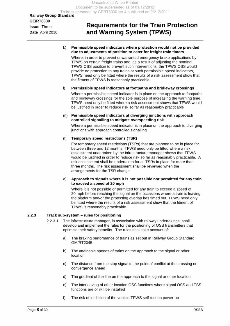
k) Permissible speed indicators where protection would not be provided due to adjustments of position to cater for freight train timers Where, in order to prevent unwarranted emergency brake applications by TPWS on certain freight trains and, as a result of adjusting the nominal TPWS OSS position to prevent such interventions, the TPWS OSS would provide no protection to any trains at such permissible speed indicators, TPWS need only be fitted where the results of a risk assessment show that the fitment of TPWS is reasonably practicable
l) Permissible speed indicators at footpaths and bridleway crossings Where a permissible speed indicator is in place on the approach to footpaths and bridleway crossings for the sole purpose of increasing the warning time, TPWS need only be fitted where a risk assessment shows that TPWS would be justified in order to reduce risk so far as reasonably practicable
m) Permissible speed indicators at diverging junctions with approach controlled signalling to mitigate overspeeding risk Where a permissible speed indicator is in place on the approach to diverging junctions with approach controlled signalling
n) Temporary speed restrictions (TSR) For temporary speed restrictions (TSRs) that are planned to be in place for between three and 12 months, TPWS need only be fitted where a risk assessment undertaken by the infrastructure manager shows that TPWS would be justified in order to reduce risk so far as reasonably practicable. A risk assessment shall be undertaken for all TSRs in place for more than three months. The risk assessment shall be reviewed when the arrangements for the TSR change
o) Approach to signals where it is not possible nor permitted for any train to exceed a speed of 20 mph Where it is not possible or permitted for any train to exceed a speed of 20 mph before reaching the signal on the occasions where a train is leaving the platform and/or the protecting overlap has timed out, TPWS need only be fitted where the results of a risk assessment show that the fitment of TPWS is reasonably practicable.
2.2.3 Track sub-system – rules for positioning 2.2.3.1 The infrastructure manager, in association with railway undertakings, shall
develop and implement the rules for the positioning of OSS transmitters that optimise their safety benefits. The rules shall take account of:
a) The braking performance of trains as set out in Railway Group Standard GM/RT2045
b) The attainable speeds of trains on the approach to the signal or other location
c) The distance from the stop signal to the point of conflict at the crossing or convergence ahead
d) The gradient of the line on the approach to the signal or other location
e) The interleaving of other location OSS functions where signal OSS and TSS functions are or will be installed
f) The risk of inhibition of the vehicle TPWS self-test on power-up
Uncontrolled When Printed Document to be superseded as of 01/12/2012
To be superseded by GERT8030 Iss 4 published on 03/12/2011

Requirements for the Train Protection and Warning System (TPWS)
Railway Group Standard GE/RT8030 Issue Three Date April 2010
RSSB Page 9 of 39
g) The risk of unwarranted intervention during movements in the opposite direction on bi-directional or reversible lines.
2.2.3.2 The provision and positioning of the TPWS track sub-system is dependent upon track layout, the location of signals and the attainable speed of trains. The provision and positioning of the TPWS track sub-system shall be reviewed if a change to the infrastructure or the operational use of the railway is proposed which may affect the track layout, signal location or the attainable speed of trains.
2.2.4 Train sub-system – provision of 2.2.4.1 Railway undertakings shall ensure that TPWS is provided for SPAD mitigation on
all trains that operate over lines fitted with the TPWS track sub-system.
2.2.4.2 Railway undertakings shall ensure that the operation and maintenance of the TPWS train sub-system and its control of the braking system continues to meet the requirements of this document. Availability requirements are set out in 2.5.3.
2.2.5 Train sub-system – permissible non-provision of TPWS 2.2.5.1 It is permissible for the railway undertaking not to provide TPWS train sub-system
functionality in the circumstances set out below:
a) Train operation in a T3 possession To temporarily isolate the TPWS train sub-system of vehicles fitted with TPWS when working in a T3 possession and to not fit TPWS to those vehicles which are authorised to operate solely in T3 possessions
b) Temporary block working To temporarily isolate the TPWS train sub-system so that a train can pass signals at danger, with authority, in accordance with GE/RT8000
c) Active cab not at the front of the train To temporarily isolate the TPWS train sub-system on driving units with an active cab not at the front of the train, in accordance with GE/RT8000
d) Shunting locomotives To shunting locomotives which are not fitted with AWS and which operate over a route which has been risk assessed. The risk assessment needs to demonstrate that either there is a very low risk because the movement of the train only occurs infrequently and at times of little other traffic and possibly where the speed of all of the traffic is very low or, where there is absolutely no risk, such as those where the locomotive works entirely inside a depot and where the rail connection to the national network is made through a trap point or where there are no TPWS fitted signals
e) Where alternative train protection system(s) are provided Where alternative train protection system(s) which are compliant with the Railway Safety Regulations: 1999 are fitted on both the train and the track over which the train is to operate.
2.3 Interface requirements - track sub-system 2.3.1 General
2.3.1.1 The following interface requirements shall be provided to ensure safe interworking with the train sub-system.
Uncontrolled When Printed Document to be superseded as of 01/12/2012
To be superseded by GERT8030 Iss 4 published on 03/12/2011

Railway Group Standard
Requirements for the Train Protection and Warning System (TPWS)
GE/RT8030 Issue Three Date April 2010
Page 10 of 39 RSSB
2.3.2 Track transmitter positioning 2.3.2.1 The track transmitters shall be positioned between the running rails on the
longitudinal centre line of the track, as set out in Appendices A to D.
2.3.3 Interface between track transmitter and signal 2.3.3.1 The track transmitters of signals selected for fitment shall be interfaced to the
signalling system so as to energise when the signal is required to be controlled to danger. (This means that no element of the signal is required to show a proceed aspect.)
2.3.4 Track transmitter frequencies 2.3.4.1 When the track transmitter(s) are required to be energised, the TPWS track
sub-system shall transmit the appropriate frequencies set out in Tables 1 and 2.
Arming Frequency
Trigger Frequency
Valid sequence 1 64.25 kHz (f1) Followed by 65.25 kHz (f2)
Valid sequence 2 64.75 kHz (f4) Followed by 65.75 kHz (f5)
Table 1 Track transmitter frequencies for overspeed sensor
Arming
Frequency Trigger
Frequency
Valid sequence 3 66.25 kHz (f3) then, while still detecting f3
65.25 kHz (f2)
Valid sequence 4 66.75 kHz (f6) then, while still detecting f6
65.75 kHz (f5)
Table 2 Track transmitter frequencies for train stop
2.3.4.2 It is permissible to use either sequence of track transmitter frequencies to provide
the appropriate function in either direction, subject to meeting the requirements of 2.3.12. The frequencies f1, f2 and f3 set out in Tables 1 and 2 shall be known as frequency set A. The frequencies f4, f5 and f6 set out in Tables 1 and 2 shall be known as frequency set B.
2.3.5 Track transmitter frequencies at other locations 2.3.5.1 Transmission of the appropriate frequencies in Table 1 shall be used at other
locations. Except as set out below, the track transmitters provided at other locations shall be permanently energised. Where there is no suitable trackside power supply it is permissible to energise the track transmitters to coincide with the passing of a train on the line concerned.
2.3.6 Track sub-system fault reporting 2.3.6.1 The infrastructure manager shall have arrangements in place to identify the
failure of the track sub-system to transmit a magnetic field when it is required. For TPWS fitted to signals, the means of notification of failure shall be both immediate and automatic, in order that an alternative safe system of working of trains can be implemented without undue delay. For TPWS fitted at other locations, a risk assessment shall be carried out to determine the most appropriate method of failure notification.
Uncontrolled When Printed Document to be superseded as of 01/12/2012
To be superseded by GERT8030 Iss 4 published on 03/12/2011

Requirements for the Train Protection and Warning System (TPWS)
Railway Group Standard GE/RT8030 Issue Three Date April 2010
RSSB Page 11 of 39
2.3.7 TSS magnetic field overlap 2.3.7.1 For a train stop, the arming frequency and trigger frequency shall be presented in
the sequence set out in Table 2, and in such a way that the two magnetic fields overlap in the area between the two track transmitters.
2.3.8 TSS and OSS magnetic fields 2.3.8.1 The magnetic fields emitted from the track transmitters shall:
a) Except for buffer stops, comply with the magnetic field strength requirements set out in Appendices C and E
b) Comply with Appendices D and E for the approach to buffer stops only
c) Be transmitted as un-modulated sinusoidal carriers
d) Not vary by more than ± 10 Hz from the frequencies set out in Tables 1 and 2
e) Between the 90 nT zones of the two track transmitters that make up a TSS, over the same height/offset profile set out in Appendix E:
i) Be greater than 45 nT from both track transmitters
ii) Not exhibit any inflection or reversal of slope of the magnetic field
iii) Be greater than 70 nT at the point where their magnetic field strengths are equal.
2.3.9 TSS and OSS magnetic field measurement 2.3.9.1 When the track transmitters have been installed, compliance with the magnetic
field frequencies and strengths set out in Tables 1 and 2 and 2.3.8 of this document shall be validated. Any validation measurements of the magnetic field frequencies and strengths shall be taken in free space using a device that is polarised to detect the vertical component of the magnetic field.
2.3.10 Track sub-system line speed limits of operation 2.3.10.1 The track sub-system shall be suitable for operation at line speeds of up to at
least 125 mph (200 km/h) or 50 mph (80 km/h) for buffer stop protection. The OSS shall be designed such that, by suitable spacing of the arming and trigger frequency transmitters, speeds as low as 15 mph (24 km/h) for signals and speed restrictions and 10 mph (16 km/h) for buffer stops shall be detected. The TSS shall enable speeds greater than 0 mph (0 km/h) to be detected so that any movement over the TSS in the correct direction shall be detected and a brake application demanded. The quoted speeds shall be within -0 to +10%.
2.3.11 TSS positioning 2.3.11.1 The TSS transmitters shall normally be positioned at or near the longitudinal
position of the signal, as shown in Figure 2. The distance from the centre of the TSS to the position of the leading wheelset when the signal normally reverts to danger shall not normally be less than 3.5 m. Where it is not possible to position the TPWS transmitters, as shown in Figure 2, the infrastructure manager shall develop and implement a strategy for TSS positioning. Such positioning shall avoid the situation where the train replaces the signal to danger before the active TPWS receiver on the train passes over the track sub-system, to avoid an unwarranted brake application.
Uncontrolled When Printed Document to be superseded as of 01/12/2012
To be superseded by GERT8030 Iss 4 published on 03/12/2011

Railway Group Standard
Requirements for the Train Protection and Warning System (TPWS)
GE/RT8030 Issue Three Date April 2010
Page 12 of 39 RSSB
≥3.5 m
f2 f3
Point where the train returns the signal to danger
Arming transmitter
Trigger transmitter
Direction of travel
Figure 2 Position of the train stop transmitters
2.3.12 Track sub-system interleaving and nesting 2.3.12.1 It is permissible to interleave or nest the TSS or OSS transmitters using one set
of frequencies, either set A or set B with TSS or OSS transmitters of the other set of frequencies, either set B or set A, as appropriate. Interleaving or nesting of TSS or OSS transmitters of the same frequency set shall not be permitted. The presence of a frequency from the other frequency set shall not prevent the train sub-system from correctly reacting to the trigger frequency of the first set.
2.4 Interface requirements - train sub-system 2.4.1 Train sub-system detection of track sub-system
2.4.1.1 The train sub-system shall be capable of detecting the magnetic fields emitted by the track sub-system, as set out in 2.3, when the active part of the receiver that detects the emissions passes through the prescribed 90 nT part of the magnetic field set out in Appendix D. The detection of the emissions shall then be used to calculate whether a brake application is required. The train sub-system shall respond to field strengths of 60 nT or more. Once a magnetic field has been detected, detection shall be retained as long as the field strength remains above 30 nT, and lost if the field strength falls below 10 nT. To avoid spurious tripping during bi-directional operation, the train sub-system shall not hold detection of an arming frequency for a period greater than 150 milliseconds.
2.4.2 Overspeed sensor system 2.4.2.1 The OSS train sub-system shall detect the presence of an appropriate arming
frequency and then start the trigger delay timer.
2.4.2.2 The trigger delay timer shall be set to one of two timings, either:
a) Corresponding to trains whose braking characteristics are equivalent to that of passenger trains, or
b) Corresponding to trains whose braking characteristics are equivalent to that of freight trains.
2.4.2.3 This allows trains with these two differing braking performances to interpret a given transmitter spacing as a different set speed. The trigger delay timer on the trains shall be set to the appropriate value set out in Table 3.
Uncontrolled When Printed Document to be superseded as of 01/12/2012
To be superseded by GERT8030 Iss 4 published on 03/12/2011

Requirements for the Train Protection and Warning System (TPWS)
Railway Group Standard GE/RT8030 Issue Three Date April 2010
RSSB Page 13 of 39
Set speed adjustment Trigger delay timer settings (+/-2 ms)
Freight train braking performance 1218 ms
Passenger train braking performance
974 ms
Table 3 Trigger delay timer settings
2.4.2.4 Where there is a mechanism for selecting whichever of the above braking performances is appropriate to the operation of the train (for example, by the use of the passenger/freight selection switch), then the selection of the braking rate shall automatically select the correct trigger delay timer setting. Where there is no mechanism for selecting whichever of the above braking performances is appropriate to the operation of the train, the trigger delay timer shall be permanently set to that which is appropriate to the braking rate of the train. All stated and implied speeds in this document are based on the 974 ms timer setting.
2.4.2.5 If the trigger delay timer reaches the trigger delay timer setting before detecting the appropriate trigger frequency, then the train sub-system shall reset and no brake application shall be made.
2.4.2.6 If the appropriate trigger frequency is detected before the trigger delay timer reaches the trigger delay timer setting, then a maximum available, maximum integrity, automatic brake application shall immediately be initiated.
2.4.2.7 The valid OSS frequency sequences are set out in Table 1. The train sub-system shall respond to valid OSS frequency sequences even when OSS transmitters are interleaved (see 2.3.12). The train sub-system shall not make an OSS brake application in any other circumstance.
2.4.2.8 A visual indication that the train sub-system has initiated a TPWS brake application shall be presented to the driver. The visual indication shall be a primary instrument, the design and positioning of which shall be in accordance with the requirements set out in GM/RT2161.
2.4.2.9 The brake application and the visual indication shall be maintained until:
a) At least 59 seconds have elapsed since the initiation of the brake application, and
b) The train sub-system has received an acknowledgement from the driver.
2.4.2.10 The nature of the visual indication to the driver is set out in Appendix F.
2.4.2.11 The train sub-system shall not permit the driver to use the override or temporary isolation facilities, set out in 2.4.4.1 and 2.4.4.4, to cancel the OSS brake application.
2.4.2.12 The OSS shall enable speeds of at least 15 mph (24 km/h) for signals and speed restrictions, and 10 mph (16 km/h) for buffer stops, up to at least 125 mph (200 km/h) to be detected. The quoted speeds shall be within -0 to +10%.
2.4.3 Train stop system 2.4.3.1 The TSS train sub-system shall firstly detect the presence of an appropriate
arming frequency.
Uncontrolled When Printed Document to be superseded as of 01/12/2012
To be superseded by GERT8030 Iss 4 published on 03/12/2011

Railway Group Standard
Requirements for the Train Protection and Warning System (TPWS)
GE/RT8030 Issue Three Date April 2010
Page 14 of 39 RSSB
2.4.3.2 If, before detecting the loss of the arming frequency, the train sub-system detects the presence of the appropriate trigger frequency, then a maximum available, maximum integrity, automatic brake application shall immediately be initiated.
2.4.3.3 The valid TSS frequencies are set out in Table 2. The train sub-system shall not make a TSS brake application in any other circumstance.
2.4.3.4 A visual indication that the train sub-system has initiated a TPWS brake application shall be presented to the driver. The visual indication shall be a primary instrument. The requirements for the design and positioning of primary instruments are set out in GM/RT2161.
2.4.3.5 The brake application and the visual indication shall be maintained until:
a) At least 59 seconds have elapsed since the initiation of the brake application, and
b) The train sub-system has received an acknowledgement from the driver.
2.4.3.6 The nature of the visual indication to the driver is set out in Appendix F.
2.4.3.7 The train sub-system shall not permit the driver to use the override or temporary isolation facilities, set out in 2.4.4.1 and 2.4.4.4, to cancel the TSS brake application.
2.4.3.8 The TSS shall enable speeds greater than 0 mph (0 km/h) to be detected, up to at least 125 mph (200 km/h). The quoted speeds shall be within -0 to +10%.
2.4.4 Isolation facilities 2.4.4.1 A facility to override the train stop function shall be provided to allow the driver to
pass, once authorised, a signal at danger. The override facility shall be positioned in the primary control area of the active driving cab. When the override facility has been operated by the driver, it shall remain active until either:
a) One active TSS has been passed, or
b) Up to 60 seconds have elapsed.
2.4.4.2 Continuous operation of the override facility shall not extend the active time of the override facility.
2.4.4.3 Where a facility is provided to fully isolate the TPWS train sub-system (for example, in the event of equipment failure) the isolation device shall meet the requirements set out in GM/RT2185. The requirements for operation of the train after isolation of the TPWS train sub-system are set out in module TW5 of GE/RT8000.
2.4.4.4 Where a facility is provided for the temporary isolation of the TPWS train sub-system, for the purpose of operating the train within an area of restrictive working (for example, for temporary block working), the isolation device shall not be within reach of the driver from the normal driving position, in order to prevent isolation of the TPWS train sub-system while the train is moving. The driver shall be provided with a prominent visual indication that a temporary isolation has been effected. The visual indication shall be visible to the driver from the normal driving position.
Uncontrolled When Printed Document to be superseded as of 01/12/2012
To be superseded by GERT8030 Iss 4 published on 03/12/2011

Requirements for the Train Protection and Warning System (TPWS)
Railway Group Standard GE/RT8030 Issue Three Date April 2010
RSSB Page 15 of 39
2.4.5 Train sub-system power-up 2.4.5.1 When a cab is made operational, any override or temporary isolations previously
applied to the train sub-system shall be removed automatically and any TPWS train sub-system faults shall be indicated to the driver.
2.4.6 Position of train sub-system receiver 2.4.6.1 The receiver on the vehicle detecting the emissions of the track transmitters shall
be positioned behind the leading wheelset. The actual position shall be such that the leading wheelset does not cause the signalling system to reset the signal to danger before the receiver has passed over the TSS track transmitters. This can be achieved by positioning the TPWS receiver no further than 2.3 m behind the leading wheelset.
2.4.7 ‘First of class’ test 2.4.7.1 Each installation design variant for a vehicle shall be subjected to a ‘first of class’
test to demonstrate compliance with the requirements set out in this document, GE/RT8030, by the TPWS train sub-system. Such ‘first of class’ test shall be undertaken when the TPWS train sub-system is installed on a vehicle, and shall demonstrate compliance under all vehicle operating conditions likely to impact on the reception of the minimum transmitted TPWS magnetic fields.
2.4.8 TPWS suppression by alternative train protection systems 2.4.8.1 It is permissible to suppress the TPWS train sub-system when a different train
protection system is providing alternative speed supervision of the train. When the suppression is removed, then any TPWS train sub-system faults shall be indicated to the driver.
2.5 System dependability 2.5.1 Interfaces
2.5.1.1 Interfaces with other safety-related control and information systems shall have no material detrimental impact on the overall safety integrity of either the signalling system or the trainborne systems.
2.5.2 Fit for purpose 2.5.2.1 The TPWS track sub-system and train sub-system shall be electrically and
mechanically fit for purpose, taking into account the environment within which they are to operate.
2.5.3 Availability 2.5.3.1 TPWS equipment shall be designed, operated and maintained to have a level of
availability that is as high as reasonably practicable, and shall be designed, as a minimum, to meet the following:
a) The train sub-system shall have an availability of not less than 99.9%. This target shall be met on a ‘per fleet, per year’ basis, not on a ‘per train, per failure’ basis (for example, the total time or mileage that trains are in service when diagnosed as having faulty TPWS equipment, but before being taken out of service in accordance with GE/RT8000, shall amount to not more than 0.1% of the total in-service time or mileage)
A fleet, for the purposes of this document, constitutes all the TPWS fitted trains that a railway undertaking owns or leases
b) The track sub-system shall have an availability of not less than 99.9%. This target shall be met on a ‘whole TPWS population, per year’ basis, not on a ‘per TPWS equipment, per failure’ basis (for example, the total time that
Uncontrolled When Printed Document to be superseded as of 01/12/2012
To be superseded by GERT8030 Iss 4 published on 03/12/2011

Railway Group Standard
Requirements for the Train Protection and Warning System (TPWS)
GE/RT8030 Issue Three Date April 2010
Page 16 of 39 RSSB
TPWS track equipment is in service when diagnosed as being faulty while trains are still permitted to operate over the line, shall amount to not more than 0.1% of the total time that the equipment is in service).
2.5.4 Post-installation compliance 2.5.4.1 In order to facilitate continuing compliance with the requirements of this
document, suitable and sufficient test equipment and procedures shall be provided and used for the maintenance and testing of TPWS equipment.
2.6 Records 2.6.1 Design and installation
2.6.1.1 A record of the design and installation of each track sub-system shall be created and maintained by the infrastructure manager.
2.6.2 Entry into rolling stock library 2.6.2.1 When TPWS is fitted to a vehicle, the railway undertaking shall, at the time of
issue of the appropriate Engineering Acceptance Certificate, supply details of the particular vehicle to the rolling stock library for entry into the vehicle register.
Uncontrolled When Printed Document to be superseded as of 01/12/2012
To be superseded by GERT8030 Iss 4 published on 03/12/2011

Requirements for the Train Protection and Warning System (TPWS)
Railway Group Standard GE/RT8030 Issue Three Date April 2010
RSSB Page 17 of 39
Part 3 Application of this Document 3.1 Application - infrastructure managers 3.1.1 Scope
3.1.1.1 The requirements of this document apply to all new and existing equipment used for, and integral with, the provision of the Train Protection and Warning System (TPWS).
3.1.1.2 It is permissible for the infrastructure manager to designate specific infrastructure projects, ongoing when this document comes into force, for which compliance with the requirements of this document applicable to the design, construction and commissioning of new or altered infrastructure is not mandatory. When designating such projects, the infrastructure manager shall consider:
a) Its responsibilities under its current safety authorisation
b) The stage reached by the project at the time this document comes into force (for example approval in principle)
c) Whether compliance is necessary to ensure compatibility with other parts of the infrastructure
d) Whether compliance is necessary to facilitate safe interworking, having regard to changes to related requirements mandated on another infrastructure manager or a railway undertaking
e) The economic impact of compliance, but subject to its current safety authorisation in relation to the infrastructure in question.
3.1.1.3 Compliance with the requirements of this document relating to inspection, maintenance and in-service condition of infrastructure is mandatory, whether or not the infrastructure concerned is the subject of a designation, as set out above.
3.1.1.4 It is permissible for the infrastructure manager to provide enhanced protection over and above that required by GE/RT8030.
3.1.2 Exclusions from scope 3.1.2.1 The requirements to provide TPWS, as set out in this document, are exempted in
the circumstances set out in 2.2.1.5 and 2.2.2.
3.1.3 General compliance date for infrastructure managers 3.1.3.1 This Railway Group Standard comes into force and is to be complied with from
7 April 2012.
3.1.3.2 After the compliance dates or the date by which compliance is achieved if earlier, infrastructure managers are to maintain compliance with the requirements set out in this Railway Group Standard. Where it is considered not reasonably practicable to comply with the requirements, authorisation not to comply should be sought in accordance with the Railway Group Standards Code.
3.1.4 Exceptions to general compliance date 3.1.4.1 There are no exceptions to the general compliance date specified in 3.1.3 for
infrastructure managers.
Uncontrolled When Printed Document to be superseded as of 01/12/2012
To be superseded by GERT8030 Iss 4 published on 03/12/2011

Railway Group Standard
Requirements for the Train Protection and Warning System (TPWS)
GE/RT8030 Issue Three Date April 2010
Page 18 of 39 RSSB
3.2 Application - railway undertakings 3.2.1 Scope
3.2.1.1 The requirements of this document apply to TPWS fitted to all new vehicles with driving cabs, except as set out in 3.2.2.
3.2.1.2 Action to bring TPWS fitted to existing vehicles into compliance with the requirements of this document is not required.
3.2.1.3 Where TPWS fitted to a vehicle is subject to alteration and the nature of the alteration provides a reasonable opportunity to bring the vehicle into conformity, then the requirements of this document applicable to the alteration apply.
3.2.2 Exclusions from scope 3.2.2.1 Exemptions from scope are permissible, as set out in 2.2.5.1.
3.2.3 General compliance date for railway undertakings 3.2.3.1 This Railway Group Standard comes into force and is to be complied with from
7 April 2012.
3.2.3.2 After the compliance dates or the date by which compliance is achieved if earlier, railway undertakings are to maintain compliance with the requirements set out in this Railway Group Standard. Where it is considered not reasonably practicable to comply with the requirements, authorisation not to comply should be sought in accordance with the Railway Group Standards Code.
3.2.4 Exceptions to general compliance date 3.2.4.1 There are no exceptions to the general compliance date specified in 3.2.3 for
railway undertakings.
3.3 Health and safety responsibilities 3.3.1 Users of documents published by RSSB are reminded of the need to consider
their own responsibilities to ensure health and safety at work and their own duties under health and safety legislation. RSSB does not warrant that compliance with all or any documents published by RSSB is sufficient in itself to ensure safe systems of work or operation or to satisfy such responsibilities or duties.
Uncontrolled When Printed Document to be superseded as of 01/12/2012
To be superseded by GERT8030 Iss 4 published on 03/12/2011

Requirements for the Train Protection and Warning System (TPWS)
Railway Group Standard GE/RT8030 Issue Three Date April 2010
RSSB Page 19 of 39
Appendix A Examples of Interleaving and Nesting of Track Transmitters
The content of this appendix is mandatory
Figure 3 Interleaving
Figure 4 Nesting
Direction of travel
Trigger transmitter f2
Trigger transmitter f5
Arming transmitter f4
Arming transmitter f1
PSR track transmitters
Signal track transmitters
Direction of travel
Trigger transmitter f5
Trigger transmitter f2
Arming transmitter f4
Arming transmitter f1
PSR track transmitters
Signal track transmitters
Uncontrolled When Printed Document to be superseded as of 01/12/2012
To be superseded by GERT8030 Iss 4 published on 03/12/2011

Railway Group Standard
Requirements for the Train Protection and Warning System (TPWS)
GE/RT8030 Issue Three Date April 2010
Page 20 of 39 RSSB
Appendix B Provision of the TPWS Track Sub-System – examples in accordance with 2.2.1
The content of this appendix is advisory
Stop Signal to rear of thesignal approaching the pointof conflict
Direction of Travel
Stop Signal immediatelyapproaching thepoint of conflict
Stop Signal to rear
Signal overlap
Point of conflictOverspeed sensorTrain stop sensor
Track Circuit Block
Figure 5 TPWS in track circuit block area, where the point of conflict is beyond the
signal overlap
Overspeed sensors
Train stop sensor Train stop sensor
Stop Signal to rear of thesignal approaching the pointof conflict
Direction of Travel
Stop Signal immediatelyapproaching thepoint of conflict
Stop Signal to rear
Signal overlap
Point of conflict
Track Circuit Block
Figure 6 TPWS in track circuit block area, where the point of conflict is within the
signal overlap
Distant Signal
Direction of Travel
First Home SignalSection Signal atnext signalbox inrear
Block clearing point
Point of conflictOverspeed sensorTrain stop sensor
Absolute Block
Station Limits
Second Home Signal
Figure 7 TPWS in absolute block area, where the point of conflict is beyond the
block clearing point but within station limits
Uncontrolled When Printed Document to be superseded as of 01/12/2012
To be superseded by GERT8030 Iss 4 published on 03/12/2011
Requirements for the Train Protection and Warning System (TPWS)
Railway Group Standard GE/RT8030 Issue Three Date April 2010
RSSB Page 21 of 39
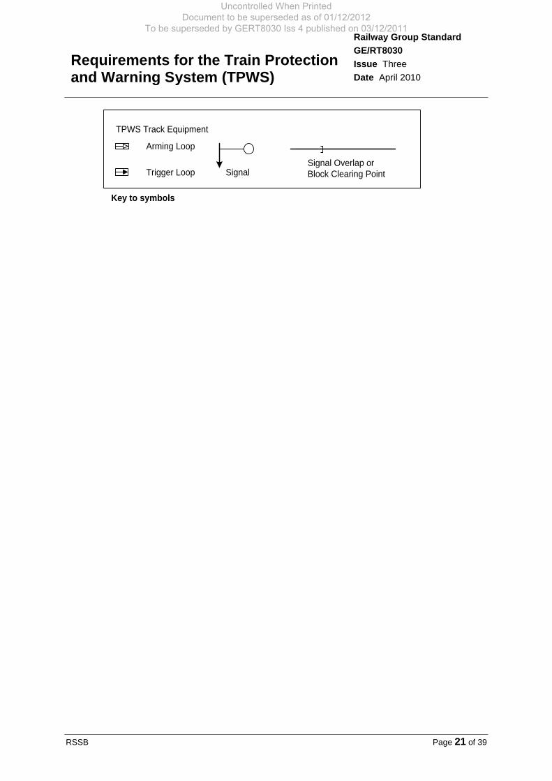
Key to symbols
SignalSignal Overlap or Block Clearing Point
Arming Loop
Trigger Loop
TPWS Track Equipment
Uncontrolled When Printed Document to be superseded as of 01/12/2012
To be superseded by GERT8030 Iss 4 published on 03/12/2011

Railway Group Standard
Requirements for the Train Protection and Warning System (TPWS)
GE/RT8030 Issue Three Date April 2010
Page 22 of 39 RSSB
Appendix C Field Strength Diagram for Track Sub-System Installations, Except for Those on the Approach to Buffer Stops
The content of this appendix is mandatory
<10 nT
<30
nT
<30
nT
450 450
A
B
<10 nT
1200
B
50
Track centre line
2400
d
A
50 2300
700 900
Indicates the volume where the magnetic field strength is undefined
Plan View
For dimension ‘d’ and detail of the 90 nT section see Appendix E
>90 nT
All dimensions in mm. Field strength is measured in free space and shown as rms values.
Volume where the magnetic field strength is >90 nT
500 500
<30
nT
<30
nT
Section A-A through track centreline
1500
1200
Indicates the volume where the magnetic field strength is undefined
<30 nT
Rail level
2300
2400
130
h
<10 nT
<10 nT
For dimension ‘h’ and detail of the >90 nT section see Appendix E
Uncontrolled When Printed Document to be superseded as of 01/12/2012
To be superseded by GERT8030 Iss 4 published on 03/12/2011

Requirements for the Train Protection and Warning System (TPWS)
Railway Group Standard GE/RT8030 Issue Three Date April 2010
RSSB Page 23 of 39
Track centre line
Appendix D Field Strength Diagram for Track Sub-System Installations on the Approach to Buffer Stops Only
The content of this appendix is mandatory
<30
nT
250 250
150 150
<30
nT
B
1400
B
1200
2400
d
A
550 300
Indicates the volume where the magnetic field strength is undefined
Plan View
For dimension ‘d’ and detail of the 90 nT section see Appendix E
Volume where the magnetic field strength is >90 nT
<10 nT <10 nT
A
For dimension ‘h’ and detail of the 90 nT section see Appendix E
All dimensions in mm. Field strength is measured in free space and shown as rms values.
Indicates the volume where the magnetic field strength is undefined
400 400
<30
nT
<30
nT
130
1500
90
<30 nT
Rail level
1400
1700
h
Volume where the magnetic field strength is >90 nT
Section A-A through track centreline
<10 nT <10 nT
Uncontrolled When Printed Document to be superseded as of 01/12/2012
To be superseded by GERT8030 Iss 4 published on 03/12/2011

Railway Group Standard
Requirements for the Train Protection and Warning System (TPWS)
GE/RT8030 Issue Three Date April 2010
Page 24 of 39 RSSB
Appendix E Field Strength through Section B-B of Appendices C and D
The content of this appendix is mandatory
This part section shows the height (h) above rail level at different distances (d) either side of the track centreline, showing where the minimum field strength requirements must be met. Other detail is omitted.
h =
310
Rail level
14
0
h =
240
h =
290
d = 100
d = 180
d = 280
>90 nT
All dimensions in mm
Track centre line
Uncontrolled When Printed Document to be superseded as of 01/12/2012
To be superseded by GERT8030 Iss 4 published on 03/12/2011

Requirements for the Train Protection and Warning System (TPWS)
Railway Group Standard GE/RT8030 Issue Three Date April 2010
RSSB Page 25 of 39
Appendix F Enhanced TPWS Functional Requirements
The content of this appendix is mandatory
F.1 Background and scope of this appendix F.1.1 This appendix sets out additional functional requirements for an enhanced Train
Protection and Warning System (TPWS) applicable to railway undertakings, as set out in Part 3.
F.1.2 The enhancement includes:
a) Changes to the TPWS Driver Machine Interface (DMI)
b) Changes to the control logic in the TPWS control unit
c) Improvements to TPWS control unit outputs
d) Improvements to the TPWS in-service fault detection.
F.1.3 GE/RT8030 Issue 2 did not specify a requirement to separately indicate brake demands caused by TPWS and AWS. The intention of the enhancement is to provide more information on board the train about the cause of an intervention.
F.1.4 GE/RT8030 Issue 2 did not specify a requirement for the TPWS system to interface with modern train-based systems, such as on-train data recorders.
F.1.5 This appendix does not include requirements for the integration of TPWS with the ERTMS/ETCS DMI. Where the TPWS is to be integrated with the ERTMS/ETCS DMI, a derogation will be required. Detailed requirements for integration of TPWS with ERTMS/ETCS will be addressed in a future issue of this document.
F.1.6 This appendix does not set out requirements relating to the retrofitment of enhanced TPWS to existing trains. Such requirements are planned to be set out in a future issue of a non-mandatory Rail Industry Standard.
F.2 TPWS DMI requirements F.2.1 TPWS DMI appearance
F.2.1.1 Figure 8 below depicts an illustrative conceptual design for a TPWS DMI that meets the enhanced functionality requirements. A dimensioned diagram is shown at Figure 9.
F.2.1.2 From top to bottom the SPAD, overspeed and AWS indicator/pushbuttons shall be aligned in that order about a common vertical axis on the left side of the panel. The three indicator/pushbuttons shall be equally spaced vertically with a tolerance of ± 1 mm.
F.2.1.3 From left to right the overspeed indicator/pushbutton, temporary isolation/fault indicator, train stop override indicator/pushbutton and brake release pushbutton shall be aligned in that order about a common horizontal axis in the centre of the panel. The overspeed indicator/pushbutton, temporary isolation/fault indicator, train stop override indicator/pushbutton and brake release pushbutton shall be equally spaced to within a tolerance of ± 1 mm.
F.2.1.4 The TPWS DMI panel shall be delineated as a separate group of controls.
Uncontrolled When Printed Document to be superseded as of 01/12/2012
To be superseded by GERT8030 Iss 4 published on 03/12/2011

Railway Group Standard
Requirements for the Train Protection and Warning System (TPWS)
GE/RT8030 Issue Three Date April 2010
Page 26 of 39 RSSB
Figure 8 Illustrative layout of TPWS DMI
F.2.1.5 The distance between the centres of the brake release pushbutton and the overspeed indicator shall not exceed 200 mm. The distance between the centres of the SPAD indicator and the AWS indicator shall not exceed 120 mm. The visual indicators/pushbuttons shall be spaced to avoid inadvertent operation of a pushbutton while operating the indicator/pushbutton next to it.
F.2.1.6 When illuminated, the indicators shall be detectable in all lighting conditions. Further requirements for controls and instruments are set out in GM/RT2161.
200 mm max.
150 mm max.
Min. diameter 10 mm
Min. lens diameter 18 mm
Min. lens width 17 mm
Min. diameter 18 mm #1
#2
#2
#3 #2 #4
#1 Indicator / pushbutton (red) #2 Indicator / pushbutton (yellow) #3 Indicator only (yellow) #4 Pushbutton (black) with hinged cover
Figure 9 Dimensioned diagram of TPWS DMI
F.2.2 DMI location F.2.2.1 The TPWS DMI is a primary control. Requirements for the positioning of primary
controls are set out in GM/RT2161.
SPAD
OVERSPEED
AWS
TEMPORARY ISOLATION/
FAULT
TRAIN STOP OVERRIDE
BRAKE RELEASE
Uncontrolled When Printed Document to be superseded as of 01/12/2012
To be superseded by GERT8030 Iss 4 published on 03/12/2011

Requirements for the Train Protection and Warning System (TPWS)
Railway Group Standard GE/RT8030 Issue Three Date April 2010
RSSB Page 27 of 39
F.2.3 Brake demand indicators F.2.3.1 Following the successful completion of the TPWS power-up test (see F.3.4), all
brake demand indicators shall be extinguished until the TPWS initiates a brake demand.
F.2.3.2 The three visual indicators (SPAD, overspeed and AWS) shall be circular and the minimum diameter of each shall be 10 mm. The indicators shall also function as pushbuttons.
F.2.3.3 The three indicators/pushbuttons shall depress by at least 2 mm when pressed.
F.2.3.4 If the indicators/pushbuttons are less than 20 mm in diameter they shall protrude above the surface of the panel by a distance which is greater than the operational stroke.
F.2.3.5 The visual indicator for a SPAD shall be red (nominally Pantone 186C). The visual indicator shall flash at a frequency of 2 Hz ± 0.25 Hz with a 50% ± 5% duty cycle when the TPWS aerial at the front of a train passes over an active TSS and a brake demand is initiated.
F.2.3.6 The visual indicator for an overspeed shall be yellow (nominally Pantone Yellow C). The visual indicator shall flash at a frequency of 2 Hz ± 0.25 Hz with a 50% ± 5% duty cycle when the TPWS aerial at the front of a train passes over an active OSS and a brake demand is initiated.
F.2.3.7 The visual indicator for an AWS brake demand shall be yellow (nominally Pantone Yellow C). The visual indicator shall flash at a frequency of 2 Hz ± 0.25 Hz with a 50% ± 5% duty cycle when a brake demand is initiated following an AWS caution warning that has not been acknowledged within the caution acknowledgement period.
F.2.3.8 The relevant visual indication shall revert to steady (‘on’) when the driver has acknowledged the appropriate alert. The acknowledgement actions are set out in F.2.8.
F.2.3.9 The relevant brake demand indication(s) shall extinguish following the cancellation of the appropriate brake demand. Brake release actions are set out in F.3.3.4.
F.2.4 Visual indication states F.2.4.1 The brake demand indicators shall display the indications as shown in the state
transition diagram in Figure 10. Transitions between indication states shall occur in accordance with the conditions shown in Figure 10.
Uncontrolled When Printed Document to be superseded as of 01/12/2012
To be superseded by GERT8030 Iss 4 published on 03/12/2011

Railway Group Standard
Requirements for the Train Protection and Warning System (TPWS)
GE/RT8030 Issue Three Date April 2010
Page 28 of 39 RSSB
Note: • OSS brake demand following TSS brake demand has no effect • AWS brake demand following TSS brake demand has no effect on visual indications • Brake release requires brake release action as set out in F.3.3 • Test sequences are not included in this diagram
Figure 10 TPWS visual indicator state transition diagram
SPAD Off Overspeed Off AWS Off
SPAD Flashing Overspeed Off AWS Off
SPAD On (Steady) Overspeed Off AWS Off
SPAD Off Overspeed Flashing AWS Off
SPAD Off Overspeed On (Steady) AWS Off
SPAD Off Overspeed Off AWS Flashing
SPAD Off Overspeed On (Steady) AWS Flashing
SPAD Off Overspeed Off AWS On (Steady)
SPAD Off Overspeed Flashing AWS On (Steady)
SPAD Off Overspeed On (Steady) AWS On (Steady)
SPAD Off Overspeed Flashing AWS Flashing
AWS Brake Demand
AWS Brake Demand
AWS Brake Demand
TSS Brake Demand
TSS Brake Demand
TSS Brake Demand
TSS Brake Demand
TSS Brake Demand
TSS Brake Demand
TSS Brake Demand
TSS Brake Demand
TSS Brake Demand
OSS Brake Demand
OSS Brake Demand
AWS Acknowledge
SPAD Acknowledge
Overspeed Acknowledge
AWS Acknowledge
AWS Acknowledge
OSS Brake Demand
AWS Brake Release Overspeed
Brake Release SPAD
Brake Release
Overspeed Acknowledge
Overspeed Acknowledge
Overspeed Brake Release
AWS Brake Release
Uncontrolled When Printed Document to be superseded as of 01/12/2012
To be superseded by GERT8030 Iss 4 published on 03/12/2011

Requirements for the Train Protection and Warning System (TPWS)
Railway Group Standard GE/RT8030 Issue Three Date April 2010
RSSB Page 29 of 39
F.2.5 Temporary isolation/fault indicator F.2.5.1 The temporary isolation/fault indicator shall illuminate to steady (‘on’) when the
TPWS is temporarily isolated.
F.2.5.2 Following a power-up test, the temporary isolation/fault indicator shall not be illuminated unless a TPWS or AWS fault has been detected.
F.2.5.3 The temporary isolation/fault indicator shall flash when a fault has been detected with the TPWS or AWS system, either during the power-up test or while the train is in service.
F.2.5.4 The flash rate to indicate a fault shall be 2 Hz ± 0.25 Hz with a 50% ± 5% duty cycle.
F.2.5.5 The temporary isolation/fault indicator shall be circular, coloured yellow (nominally Pantone Yellow C), shall have a minimum lens diameter of 18 mm, and shall not protrude above the surrounding bezel.
F.2.6 Train stop override indicator/pushbutton F.2.6.1 The train stop override indicator/pushbutton shall indicate to the driver when the
train stop override functionality has been activated.
F.2.6.2 Following a power-up test, the indicator/pushbutton shall not be illuminated until such time that the train stop override function is activated.
F.2.6.3 Except during a power-up test (see F.3.4.1), the train stop override indicator/pushbutton shall not be illuminated when train stop override is not active.
F.2.6.4 The train stop override indicator/pushbutton shall illuminate to steady (‘on’) when the train stop override functionality is active. The conditions for using the override facility are set out in 2.4.4.
F.2.6.5 The train stop override indicator/pushbutton shall be square and coloured yellow (nominally Pantone Yellow C) and shall have a minimum lens width of 17 mm.
F.2.6.6 The train stop override indicator/pushbutton shall not protrude above the surrounding bezel.
F.2.6.7 The train stop override indicator/pushbutton shall depress by at least 2 mm when pressed.
F.2.7 Audible alerts F.2.7.1 Audible alerts for brake demands
F.2.7.1.1 There shall be separate and distinct audible alerts to inform the driver of brake demands due to:
a) Operation of the TSS: (SPAD audible alert), and
b) Operation of the OSS: (overspeed audible alert).
F.2.7.1.2 The audible alerts for SPAD and overspeed events shall be speech messages, which shall be preceded by a short priming sound. The audible alert for an AWS caution is set out in GE/RT8035. The driver response to the AWS caution warning using the existing AWS caution acknowledgement push button is set out in GE/RT8035.
F.2.7.1.3 Where the TPWS train sub-system has initiated a TSS brake demand after it has initiated an OSS brake demand, the presentation of the overspeed speech
Uncontrolled When Printed Document to be superseded as of 01/12/2012
To be superseded by GERT8030 Iss 4 published on 03/12/2011

Railway Group Standard
Requirements for the Train Protection and Warning System (TPWS)
GE/RT8030 Issue Three Date April 2010
Page 30 of 39 RSSB
message shall be immediately terminated and replaced by the SPAD speech message.
F.2.7.1.4 The speech message for a SPAD audible alert shall be:
‘SPAD alert, contact the signaller’.
F.2.7.1.5 The speech message for an overspeed audible alert shall be:
‘Overspeed, contact the signaller’.
F.2.7.1.6 Once activated, the speech message shall be repeated, without the priming tone, with an interval of three seconds between the end of one announcement and the beginning of the next announcement, until acknowledged (see F.2.8.4). At least one cycle of the speech message shall be played.
F.2.7.1.7 If the alert has not been acknowledged, the volume of the speech message shall be reduced by 6 dB 60 seconds after the brakes have been applied, so that the speech message does not interfere with any communications that are required with the signaller.
F.2.7.2 Audible announcement for TPWS self-test F.2.7.2.1 There shall be a separate and distinct audible announcement to inform the driver
of the successful completion of the TPWS train sub-system self-test function.
On successful completion of the power-up test an audible announcement shall be sounded in the cab.
The speech message shall be:
‘TPWS and AWS operational’.
F.2.7.2.2 The ‘TPWS and AWS operational’ speech message shall not be preceded by a priming sound.
F.2.7.2.3 The presentation of the ‘TPWS and AWS operational’ speech message shall not interrupt or delay the announcement of the SPAD or overspeed speech messages.
F.2.7.2.4 AWS self-test requirements remain unchanged and are set out in GE/RT8035.
F.2.7.2.5 There shall be no speech announcement for TPWS or AWS faults.
F.2.7.3 General requirements for audible alerts F.2.7.3.1 All TPWS audible alerts shall be implemented in a form that can be derived from
.WAV files and can be uploaded by maintenance procedures.
F.2.7.3.2 It shall not be possible for two or more TPWS speech messages to sound simultaneously, or for any TPWS speech message and pre-announcement priming tone to sound simultaneously.
F.2.7.3.3 TPWS audible alerts shall not affect the operation of AWS audible indications. Requirements for AWS audible indications remain unchanged and are set out in GE/RT8035.
F.2.7.3.4 It shall be possible for a TPWS speech message to sound at the same time as an AWS audible indication.
Uncontrolled When Printed Document to be superseded as of 01/12/2012
To be superseded by GERT8030 Iss 4 published on 03/12/2011

Requirements for the Train Protection and Warning System (TPWS)
Railway Group Standard GE/RT8030 Issue Three Date April 2010
RSSB Page 31 of 39
F.2.7.3.5 The priming sound shall be distinguishable from all other audible indications and alerts in the cab. It is permissible for the priming sound to consist of two or more tones sounded simultaneously.
F.2.8 Acknowledgment of visual and audible alerts F.2.8.1 The SPAD alert shall be acknowledged by pressing and releasing the SPAD
indicator/pushbutton on the TPWS DMI.
F.2.8.2 The overspeed alert shall be acknowledged by pressing and releasing the overspeed indicator/pushbutton on the TPWS DMI.
F.2.8.3 Visual alerts shall change to steady immediately on detection of acknowledgement. The audible alert shall continue, if necessary, to complete the first cycle of the speech message, as set out in F.2.7.1, and shall then be silenced.
F.2.8.4 An AWS caution is acknowledged using the AWS caution acknowledgement device, as set out in GE/RT8035. This silences the AWS caution audible indication (horn), changes the AWS visual indicator to black and yellow, and shall, if an AWS brake demand has been initiated, change the AWS brake demand visual indication from flashing to steady. It shall not be possible to acknowledge an AWS caution (whether or not a brake demand has been initiated) using the brake demand indicator/pushbutton on the TPWS DMI.
F.2.8.5 Operation of the AWS caution acknowledgement device following a TSS or OSS brake application shall not acknowledge the SPAD or overspeed alert.
F.2.9 Brake release button F.2.9.1 The brake release button shall be circular with a minimum diameter of 18 mm
excluding any bezel, and shall be coloured black.
F.2.9.2 The brake release button shall depress by at least 2 mm when pressed.
F.2.9.3 There shall be a cover which protects the brake release button. The cover shall be sprung so that it automatically returns to its covering position when resistance is removed. The spring tension shall not be so great that the cover is difficult to operate using one hand. The cover shall not create a nipping hazard. The cover shall not be easily removed by the driver.
F.2.9.4 The conditions under which the brakes are released are set out in F.3.3.
F.2.10 Labelling of TPWS DMI F.2.10.1 The visual indicators shall be labelled ‘SPAD’, ‘OVERSPEED’ and ‘AWS’ to
identify the cause of the brake demand. It is permissible for the ‘OVERSPEED’ label to be shown over two rows.
F.2.10.2 The labelling of the SPAD, overspeed and AWS indicators shall be centred about a common vertical axis set to the left of the indicators to which they refer and shall be centred vertically with the applicable indicator centre.
F.2.10.3 The brake release button shall be labelled as shown below over two rows:
‘BRAKE RELEASE’
Uncontrolled When Printed Document to be superseded as of 01/12/2012
To be superseded by GERT8030 Iss 4 published on 03/12/2011

Railway Group Standard
Requirements for the Train Protection and Warning System (TPWS)
GE/RT8030 Issue Three Date April 2010
Page 32 of 39 RSSB
F.2.10.4 The temporary isolation/fault indicator shall be labelled as shown below over three rows:
‘TEMPORARY ISOLATION/
FAULT’
F.2.10.5 The train stop override indicator/pushbutton shall be labelled as shown below over two rows:
‘TRAIN STOP OVERRIDE’
F.2.10.6 The labelling of the temporary isolation/fault indicator, train stop override indicator/pushbutton and brake release button shall be centred above the centre of the corresponding indicator/pushbutton, and the rows of each label shall be vertically aligned.
F.2.10.7 The character height of the labelling shall be a minimum of 5 mm and, when viewed from the driving position, shall subtend as a minimum a visual angle of 15 minutes.
F.2.10.8 Labelling shall be:
a) Permanent and durable
b) Selected for maximum contrast against the panel background
c) In capitals and in a sans serif font.
F.2.11 Pushbutton resistance F.2.11.1 Pushbutton resistance on all buttons on a TPWS DMI panel shall be consistent
and shall be within the range 2.8 to 15 newtons.
F.2.12 Pushbutton/switch confirmatory action F.2.12.1 Pushbuttons/switches shall provide audible and tactile feedback to the driver.
F.3 System operating requirements F.3.1 Brake application
F.3.1.1 A TPWS brake demand shall initiate a train brake application in accordance with the requirements set out in 2.1.2 and 2.1.3.
F.3.2 Indication of brake demand cause F.3.2.1 The visual indications on the TPWS DMI are set out in F.2.3, and the audible
indications of brake demand cause are set out in F.2.7.
F.3.3 Brake release F.3.3.1 Following a brake application due to a TSS, OSS or AWS brake demand, the
brakes shall not be released if the driver powers the cab down and back up again. When the cab is re-initialised, the brakes shall remain applied and any brake demand indications that were illuminated on the TPWS DMI before the cab was powered down shall reappear.
F.3.3.2 The brakes shall not be released until the train has received the correct brake release action (see F.3.3.4) from the driver.
Uncontrolled When Printed Document to be superseded as of 01/12/2012
To be superseded by GERT8030 Iss 4 published on 03/12/2011

Requirements for the Train Protection and Warning System (TPWS)
Railway Group Standard GE/RT8030 Issue Three Date April 2010
RSSB Page 33 of 39
F.3.3.3 A brake release action shall only be effective if it is initiated after at least 59 seconds have passed since the initiation of the brake application and all brake demand alerts have previously been acknowledged.
F.3.3.4 Brake release actions F.3.3.4.1 Following a brake application due to a TSS brake demand, the release of the
brakes shall require the SPAD indicator/pushbutton and brake release button to be pressed simultaneously and then both released.
F.3.3.4.2 Following a brake application due to an OSS brake demand, the release of the brakes shall require the overspeed indicator/pushbutton and brake release button to be pressed simultaneously and then both released.
F.3.3.4.3 Following a brake application due to a failure to acknowledge an AWS caution warning within the caution acknowledgement period (see the requirements set out in GE/RT8035), release of the brakes requires the warning to be acknowledged and then shall require the AWS brake demand indicator/pushbutton and brake release button to be pressed simultaneously and then both released.
F.3.3.4.4 When both an overspeed and an AWS brake demand have occurred, and the overspeed and AWS brake demand indicators are both illuminated, the brakes shall be released by pressing and releasing the overspeed indicator/pushbutton together with the brake release button. Release of the brakes in this way shall clear all brake demand indications on the DMI panel.
F.3.3.4.5 When both an overspeed and an AWS brake demand have occurred, and the overspeed and AWS brake demand indicators are both illuminated, pressing and releasing the AWS indicator/pushbutton together with the brake release button shall extinguish the AWS brake demand indicator but shall not release the brakes. The OSS brake demand indicator shall remain lit.
F.3.4 Fault detection F.3.4.1 Power-up test
F.3.4.1.1 The TPWS shall perform a power-up test immediately the system is started, except when the system was previously powered down with a TSS, OSS or AWS brake demand displayed.
F.3.4.1.2 Within 0.5 seconds of the TPWS power-up test commencing, all the TPWS DMI indicators shall illuminate simultaneously and the AWS visual indicator shall display black/yellow if not already doing so, and then change to display all black. The AWS horn shall sound. Upon acknowledgement of the AWS horn by pressing and releasing the AWS caution acknowledgement device, the AWS visual indicator shall change to black/yellow, the AWS horn shall cease to sound and the AWS bell shall sound for 0.5 second + 0.5/-0 second. Upon successful completion of the power-up test all the TPWS DMI indicators will be extinguished and an audible announcement (see F.2.7.2) shall be sounded in the cab.
F.3.4.1.3 During the power-up test, the TPWS system shall initiate a brake demand. A TPWS or AWS fault detected during the power-up test shall cause the system to maintain the brake demand. Any TPWS or AWS fault detected by the system shall be indicated to the driver by flashing the temporary isolation/fault indicator and all other indicators shall be extinguished.
F.3.4.1.4 The system shall maintain the brake demand until the fault has been cleared and there has been a successful power-up test following powering down and powering up.
F.3.4.1.5 Requirements for AWS testing are set out in GE/RT8035.
Uncontrolled When Printed Document to be superseded as of 01/12/2012
To be superseded by GERT8030 Iss 4 published on 03/12/2011
Railway Group Standard
Requirements for the Train Protection and Warning System (TPWS)
GE/RT8030 Issue Three Date April 2010
Page 34 of 39 RSSB
F.3.4.2 In-service system monitoring F.3.4.2.1 The TPWS shall undertake system monitoring while in service.
F.3.4.2.2 Detection of a TPWS fault which results in loss of the protection normally provided by TPWS shall cause the temporary isolation/fault indicator to flash, but shall not apply the brakes solely due to the detection of the fault.
F.3.4.2.3 The in-service monitoring and fault display functions shall not disable or compromise the train stop or overspeed functionality of the TPWS, or the functionality of the AWS. Detection of a fault shall not suppress an existing brake demand.
F.3.4.2.4 Faults to be detected while the train is in service shall include:
a) Electrical continuity failure between the aerial and the control unit
b) Degradation in signal transfer between the aerial and the control box
c) Any other failure that could result in loss of TPWS protection.
F.3.4.2.5 The temporary isolation/fault indicator shall flash until either the system is able to confirm that the detected fault has been rectified, or the flashing indication is suppressed as the result of a brake demand or temporary isolation, as set out in F.3.4.2.6.
F.3.4.2.6 The visual indication of a detected fault through the flashing of the fault indicator on the DMI shall be suppressed automatically whenever a brake demand indicator on the TPWS DMI is illuminated or when the system is isolated by operation of the temporary isolation switch. Once the brake has been released and the brake demand indicator extinguished or the temporary isolation removed, then the fault indicator shall again flash.
F.3.5 Output requirements: on-train data recording F.3.5.1 In addition to the current on-train data recording requirements, as set out in
GM/RT2472, the enhanced TPWS shall supply suitable and sufficient outputs to facilitate connection to the on-train data recorder, to enable the status of each of the TPWS DMI functions to be recorded.
F.3.6 TPWS equipment compatibility F.3.6.1 The design of the TPWS equipment shall contain features that prevent a train
which has been fitted with an upgraded TPWS system from being fitted with a non-upgraded system during maintenance or re-fitment.
F.3.6.2 TPWS control units shall be capable of being replaced without requiring setting up for the particular type of vehicle to which they are to be fitted.
F.3.7 Powering up over active TPWS loops F.3.7.1 A TPWS fault shall not be indicated solely as a result of powering up the system
while the train is standing over an active TPWS loop.
Uncontrolled When Printed Document to be superseded as of 01/12/2012
To be superseded by GERT8030 Iss 4 published on 03/12/2011

Requirements for the Train Protection and Warning System (TPWS)
Railway Group Standard GE/RT8030 Issue Three Date April 2010
RSSB Page 35 of 39
Appendix G Guidance on Audible Alerts
The content of this appendix is for guidance only
G.1 General guidance on speech alerts G.1.1 Separate speech files should be produced for each announcement and priming
tone.
G.1.2 A female voice should be used for the speech messages. The message should be presented in a formal, impersonal manner and given in English.
G.1.3 The speech warning should have at least three frequencies in the range 300-3000 Hz, to reduce the likelihood of masking.
G.1.4 The speech messages should be audible relative to ambient noise, but should not be so loud as to cause alarm to the driver. The volume of the speech warnings should be within the range 65-90 dBA.
G.1.5 If automatic volume adjustment is provided, the level of the speech warning and priming tone should be automatically adjusted such that the speech warning (measured at the approximate position of the driver’s ear) is maintained at 10-15 dB above ambient noise in the train cab. If automatic volume adjustment is not provided, the level of the speech warning and priming tone should be set to produce a speech warning that is approximately 10-15 dB above the normally expected ambient noise in the train cab (measured at the approximate position of the driver’s ear). After 60 seconds the volume of the speech warning should be reduced by 6 dB in accordance with F.2.7.1.7.
G.1.6 The sound level and, where provided, the operation of the automatic volume adjustment of the speech warnings, should be checked on initial installation and, when necessary, during maintenance activities. This check can be done by an objective test using measuring equipment (see G.2.1) and/or by a subjective test using end users (see G.2.2).
G.1.7 Guidance on audible alerts is available in the RSSB Alarms and Alerts Guidance and Evaluation Tool.
G.2 Checking sound level of speech alerts G.2.1 Objective tests
G.2.1.1 The ‘Good Practice Guide for the design of alarms and alerts’ (RSSB research project T326) sets out an objective test using the software Detectsound. Detectsound runs under Microsoft windows on IBM compatible computers. The program calculates the highest and lowest recommended sound levels for audible warnings in a given ambient noise spectrum. Detectsound also takes into account variability in hearing ability.
G.2.1.2 Before taking any noise measurements, the audiometer should be calibrated using a sound of known loudness. Sound calibrations should comply with Class 1 or Class LS of BS EN 60942:2003 Electroacoustics: Sound calibrators.
G.2.2 Subjective tests G.2.2.1 Subjective tests mainly provide information about whether a warning is too quiet.
Subjective tests also help to inform whether the warning is startling. It is important to include a number of drivers in the subjective tests (eight is recommended, representing the full age range of the driver population). It is important to test the warnings on a number of drivers, because hearing ability varies between individuals and this will also gain ‘buy in’ to the process.
Uncontrolled When Printed Document to be superseded as of 01/12/2012
To be superseded by GERT8030 Iss 4 published on 03/12/2011

Railway Group Standard
Requirements for the Train Protection and Warning System (TPWS)
GE/RT8030 Issue Three Date April 2010
Page 36 of 39 RSSB
G.2.2.2 The subjective tests should preferably be undertaken in the actual environment. It is recommended that each listener should be presented with the warning at least five times and asked whether it is:
a) Clearly audible
b) Not clearly audible
c) Too loud.
G.2.2.3 The warnings should be played to the driver under a range of operational conditions, for example, stationary, low speed, high speed.
G.2.2.4 The warning should only be considered audible if all of the listeners confirm that the warning is clearly audible under all conditions. If this is not the case, then consultation with an acoustic expert would be beneficial.
Uncontrolled When Printed Document to be superseded as of 01/12/2012
To be superseded by GERT8030 Iss 4 published on 03/12/2011

Requirements for the Train Protection and Warning System (TPWS)
Railway Group Standard GE/RT8030 Issue Three Date April 2010
RSSB Page 37 of 39
Definitions and Abbreviations Arming frequency A frequency generated by the track sub-system which, when detected by the vehicle, arms the train sub-system.
Automatic Warning System (AWS) The Automatic Warning System (AWS) is provided to give train drivers in-cab warnings of the approach to signals, reductions in permissible speed and temporary/emergency speed restrictions, and to apply the brakes in the event that a driver does not acknowledge cautionary warnings given by the system.
Danger (signal at) Signal indicating STOP.
Driver machine interface (DMI) The driver machine interface provides indications to the driver of the system status, as well as allowing the driver to control selected system functions.
‘First of class’ test The method of demonstrating, on the first of a class or sub-class of vehicles to be built or modified, that the design meets the requirements of a specification or part of a specification.
Interleaving Interleaving is the term used where the arming or trigger transmitter of one pair of track transmitters is positioned between a different pair of track transmitters. (See Appendix A Figure 3.)
Nesting Nesting is the term used where one pair of track transmitters is positioned in between a different pair of track transmitters. (See Appendix A Figure 4.)
Other location Those parts of the infrastructure where an overspeed sensor system (OSS) is to be fitted for reasons other than protecting against SPADs.
Overspeed sensor system (OSS) The overspeed sensor system (OSS) is a facility whose function is to initiate a brake application on a train that approaches a signal showing a danger aspect, or other location, at excessive speed.
Set speed Set speed is the minimum speed at which a brake application is initiated when a train passes over the track elements of an active OSS.
SPAD Signal passed at danger.
TPWS Train Protection and Warning System.
TPWS temporary isolation switch A switch provided in the cab whereby the TPWS can be temporarily isolated (as set out in 2.4.4.4).
Uncontrolled When Printed Document to be superseded as of 01/12/2012
To be superseded by GERT8030 Iss 4 published on 03/12/2011

Railway Group Standard
Requirements for the Train Protection and Warning System (TPWS)
GE/RT8030 Issue Three Date April 2010
Page 38 of 39 RSSB
Track sub-system The track sub-system comprises the components mounted on the track or at the trackside that are used to provide the train stop system (TSS) and OSS functionality.
Train stop override The facility that allows a train to pass a signal at danger without invoking a brake demand caused by the train stop system (TSS).
Train stop system (TSS) The train stop system (TSS) is a facility whose function is to initiate a brake application on a train that passes a signal at danger without authority.
Train sub-system The train sub-system comprises the components mounted on vehicles that are used to provide TSS and OSS functionality.
Trigger delay The pre-set period timed by the train sub-system and initiated by detection of an OSS arming frequency.
Trigger frequency A frequency generated by the track sub-system which, when detected by the vehicle, triggers the train sub-system.
TSR Temporary speed restriction.
Vehicle For the purposes of this standard the term vehicle is used to define that part of a train which is fitted with the TPWS equipment, where ‘train’ has the same meaning as in section 83(1) of the Railways Act 1993.
Uncontrolled When Printed Document to be superseded as of 01/12/2012
To be superseded by GERT8030 Iss 4 published on 03/12/2011

Requirements for the Train Protection and Warning System (TPWS)
Railway Group Standard GE/RT8030 Issue Three Date April 2010
RSSB Page 39 of 39
References The Catalogue of Railway Group Standards and the Railway Group Standards CD-ROM give the current issue number and status of documents published by RSSB. This information is also available from www.rgsonline.co.uk.
Documents referenced in the text RGSC 01 The Railway Group Standards Code Railway Group Standards GE/RT8000 Rule Book GE/RT8035 Automatic Warning System GM/RT2045 Braking Principles GM/RT2161 Requirements for Driving Cabs of Railway Vehicles GM/RT2185 Train Safety Systems GM/RT2472 Data Recorders on Trains – Design Requirements Other references BS EN 60942:2003 Electroacoustics: Sound calibrators ISBN 0 1054 4393 X Railways Act 1993 ISBN 0 7176 2442 0 Railway Safety Regulations: 1999 – Guidance on Regulations RSSB research project T326 – Good Practice Guide for the design of alarms and alerts,
and RSSB Alarms and Alerts Guidance and Evaluation Tool (available on the RSSB website)
Other relevant documents RSSB documents GM/GN2169 Combined Manual for AWS and TPWS Trainborne Equipment
Uncontrolled When Printed Document to be superseded as of 01/12/2012
To be superseded by GERT8030 Iss 4 published on 03/12/2011