research and design of conduit air propeller lifeboat
TRANSCRIPT

Research and Design of Conduit Air Propeller Lifeboat
Guocai Chena, Zongyu Lib, Wenkang Guoc, Xuan Zangd, Zhiyuan Xue, * School of Navigation and Naval Architecture, Dalian Ocean University, Dalian 116000, China
[email protected], [email protected], [email protected], [email protected], [email protected]
*Corresponding author
Keywords: ducted, air propeller, lifeboat
Abstract: This article briefly introduces the basic theory and design ideas of ducted air propeller lifeboats. Through experimental simulations, the calculated theoretical values are consistent with the actual measured values of the model, which further proves the feasibility of this ship.
1. Introduction Most modern ship propellers are set on the bottom of the ship, and the propellers are set on the
bottom of the hull. The propellers are too noisy and can easily be caught in marine plants such as sea grass when rotating, causing the propellers to stop moving. Marine life causes harm and damages the marine ecological environment.
In order to avoid the above problems, strengthen the protection of marine ecology, and improve the level of fishery development, this paper proposes a lifeboat based on the ducted air propeller design. The ducted air propeller replaces the traditional underwater propeller lifeboat, which is simulated by Simple Planes animation, Rhino3D modeling, laser engraving ABS, this ship model has been successfully launched, and it is feasible in practice. Experimental simulations show that the ship can effectively avoid the generation and spread of underwater noise and reduce the damage to aquatic life. In addition to the above characteristics, the ship the ship is highly mobile, can adapt to a variety of environments, has a lower cost, and is more novel than existing ships. It still has certain development potential in the areas of future ecological protection, tourism development, military applications, fisheries and fishing.
2. Basic theory of ducted air propeller lifeboats 2.1 Thruster
The thrust generated by the propeller is provided by the air propeller. When calculating the thrust of the propeller, the momentum on the cross section of the propeller is calculated using momentum and lutein theory, and then the integral thrust of the propeller can be used to obtain the thrust of the propeller. First calculate the propeller cross section. The inference coefficient is as follows:
(1)
In the formula, and express the lift coefficient and drag coefficient of the section,
respectively, β represents the angle of attack of the section. According to the coefficient , the thrust of the propeller can be calculated. The following formula
is the calculation formula:
(2)
iC
ββ sincos ×−×= XYi CCC
YC XC
iC
drkCbT iiP ××= ∫1
r
2
0
ω
2020 2nd International Conference on Electronic Science and Automation Control (ESAC 2020)
Published by CSP © 2020 the Authors 48
In the formula: ω represents the flow velocity of the section, m / s; b represents the width of the
section, m; represents the coefficient, , represents the propeller thrust, N.
2.2 Resistance to the hull The resistance of a ship in the water, caused by waves, viscous friction between water and the hull
surface, and water resistance caused by the vortex phenomenon that may appear at the stern. Water resistance consists of friction resistance, wave resistance, viscous pressure resistance and other resistance the total resistance is generally expressed as:
(3)
Where expresses friction resistance, expresses remaining resistance (including wave
resistance and viscous pressure resistance)
2.2.1 Friction resistance Fu Rude assumes that the frictional resistance of the hull is equal to the frictional resistance of a
flat plate with the same speed, the same length, and the same wet area. The following is the formula for calculating the frictional resistance of a flat plate:
(4)
In the above formula, expresses the friction resistance coefficient, expresses the roughness
compensation coefficient, ρ expresses the density of water, kgf / .S expresses wet area, .ν expresses speed, m / s. expresses friction resistance, kgf.
2.2.2 Wave resistance The wave-making resistance is related to the speed and the geometry of the hull. When the speed
increases, the wave-making resistance increases. The variation law is closely related to the Fu Ruide number . The following formula is the formula for Fu Rude number :
(5)
In the above formula, ν is the speed, m / sg is the acceleration of gravity, and / s L is the length of
the ship, m.
3. Lifeboat design for ducted air propellers 3.1 Basic design
First design the propeller. The first end of the shaft is drivingly connected to the output shaft of the internal combustion engine. The shaft drives the propeller to rotate, so that power is generated. The maximum thrust generated by the propeller is used to calculate the diameter, power and static thrust of the propeller. In the process of selecting the propeller for the propulsion, because the propeller is in the air as a whole, selecting the aircraft propeller will get better results. At the same time, installing a fixed duct around the air propeller can effectively improve the efficiency of the propeller and Thrust of the thruster.
According to the reasoning and efficiency of the air duct propeller, the size and proportion of the hull are further designed. Since the air duct propeller is located above the hull, the ship has no
ik Rzki ρ21
= PT
rt RRR +=
tR rR
2
21)( νρSCCR ttt ∆+=
tC tC∆2S 4m 2m
tR
nF nF
gLFn
ν=
2m
49
excess structure, the bottom of the ship is smooth, the resistance is reduced, and the speed of the ship is increased.
The hull width and depth are determined based on the resistance generated by the hull, the frictional resistance, the wave-making resistance, and the hull stability coefficient to design the hull.
3.2 Detailed design of lifeboat with ducted air propeller 3.2.1 Design of duct air propeller
Install a fixed casing around the shaft and the air propeller, that is, the duct (the duct can be divided into a tapered duct, a reduced duct, which can increase or slow the air velocity, respectively, to achieve a change in ship speed). The first end is drivingly connected to the output shaft of the internal combustion engine, and the second end of the rotating shaft is connected to the propeller. The internal combustion engine has a certain power and the rotating shaft drives the propeller to rotate at a certain speed. A tapered duct can be used to change the air flow velocity of the duct air propeller. Thus the air is pushed, and the forces are mutual, which pushes the ship forward.
3.2.2 Thruster efficiency issues The power output by the ship's main engine is transmitted to the thruster through the main shaft.
There must be an energy transfer loss between the two. In addition, there is also an efficiency problem in the thruster itself. The combination of the two losses requires the calculation of the total efficiency. Much greater than the effective power to propel the ship. Can be expressed as:
(6)
The formula represents the effective power of and the power of machine, μ is called the
propulsion coefficient, which is a comprehensive value of efficiency. The larger the value, the better the propulsion efficiency of the ship. In addition, if the power is calculated in kW (or hp), the effective power can be expressed as:
(KW), (hp) (7)
In the above formula, r represents the total resistance, n. represents the effective thrust to
propel the ship forward, n.
3.2.3 Resistance to the hull The power plant of this lifeboat is not in the water, there is no redundant structure, the bottom of
the ship is smooth, and the resistance is greatly reduced. When calculating the resistance, it belongs to the type of high-speed ships, and the total friction force is the main part of the ZTE wave resistance, about 50% of the total resistance.
3.2.4 Functional requirements The bottom of the new ship is smooth and has no unnecessary structure. The water movement is
changed to aerodynamics. The steering is also controlled by air duct propellers. It has high flexibility and the propulsion system is located at the stern, which makes the center of gravity move backward. In the process of forward, the bow is slightly warped and faster. Can make ships land from the sea and land from the sea. Because the ship speed is 0 when the ship starts, the static friction on the ground at the bottom of the hull increases with the increase of thrust, and it can reach the maximum static friction, so the static thrust of the air duct propeller must be greater than the maximum static friction experienced by the hull. The static friction can be regarded as sliding friction. (The static thrust of the propeller refers to the maximum thrust generated by the propeller
be PP /=η
eP bP
102102νν e
eTRp ==
7575νν e
eTRp ==
eT
50

when the main engine is operating normally. The relationship between the static thrust of the propeller and the diameter of the propeller [2], the following formula is the calculation formula:
(8)
In the above formula, represents the power of the propeller, represents the diameter of the
propeller, t represents the static thrust of the propeller, and n. The formula for calculating the maximum static friction on the bottom of the hull:
(9)
In the above formula, indicates the friction coefficient of the material at the bottom of the hull,
indicates the force of the ship's own weight and load against the ground, and indicates the maximum static friction force on the ground at the bottom of the hull, N.
3.2.5 Security requirements Stability is an important part of ship design. According to the stability theorem, the ship's
inclination angle is less than 15°, and the stability of the ship is greatly improved. However, in order to achieve the landing of the survival ship directly from the sea and prevent the impact from affecting the hull, the survival ship The forehead bulkhead is thickened as a whole, and the air inlet of the air duct propeller casing is provided with a protective net to prevent debris and even personnel from being caught during high-power work.
The lifeboat uses aerodynamic propellers as the thrust source. Due to the low efficiency, higher power motors are required. During the starting and steering process, there is a problem of excessive motor torque. Excessive torque may cause the hull to be unstable or even topple, and the hull is stable. Determined by the depth and width, the following formula is the hull stability factor:
In the above formula, b indicates the hull width, d indicates the hull depth, and indicates the hull stability coefficient.
When the ship's lateral inclination angle is less than the angle θ, its restoring moment can return the hull to the normal floating state. The following formula is the calculation formula of the restoring moment:
In the above formula, Δ represents the displacement of the ship, t.GM represents the initial stability height of the ship, mM represents the recovery moment, and tm.
4. Experimental simulation of a lifeboat with ducted air propellers The following are three views of the 1:20 ducted air propeller lifeboat model, the modeling model
and the main parameters of the experiment based on the overall design idea: The experimental simulation lifeboat is mainly composed of ducted air propeller, console and hull.
SS
P PP
D ××
××××= 326
3-
1.34103.28(105.12T )
SP PD
NM Ff µ=
µ
NF Mf
DBTS =
ST
θsinGMGKM •∆=•∆=
51
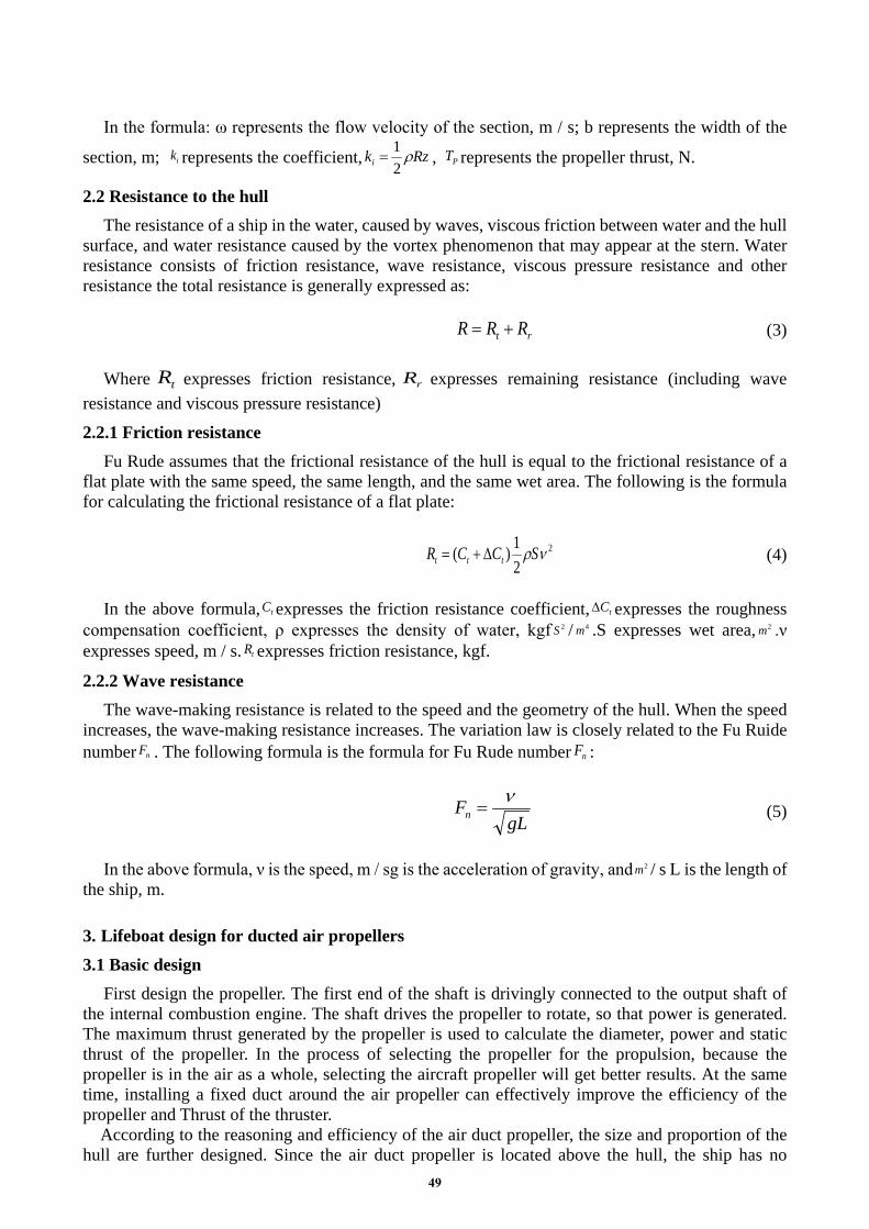
1-hull; 2-c station antenna; 3-console; 4-blower; 5-rudder blade
Figure 1. Hull sketch
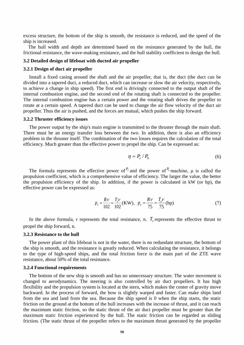
6-housing; 7-propeller; 8-rotating shaft; 9-filter; 10-air inlet; 11-air outlet
Figure 2. Specific structure of duct air propeller
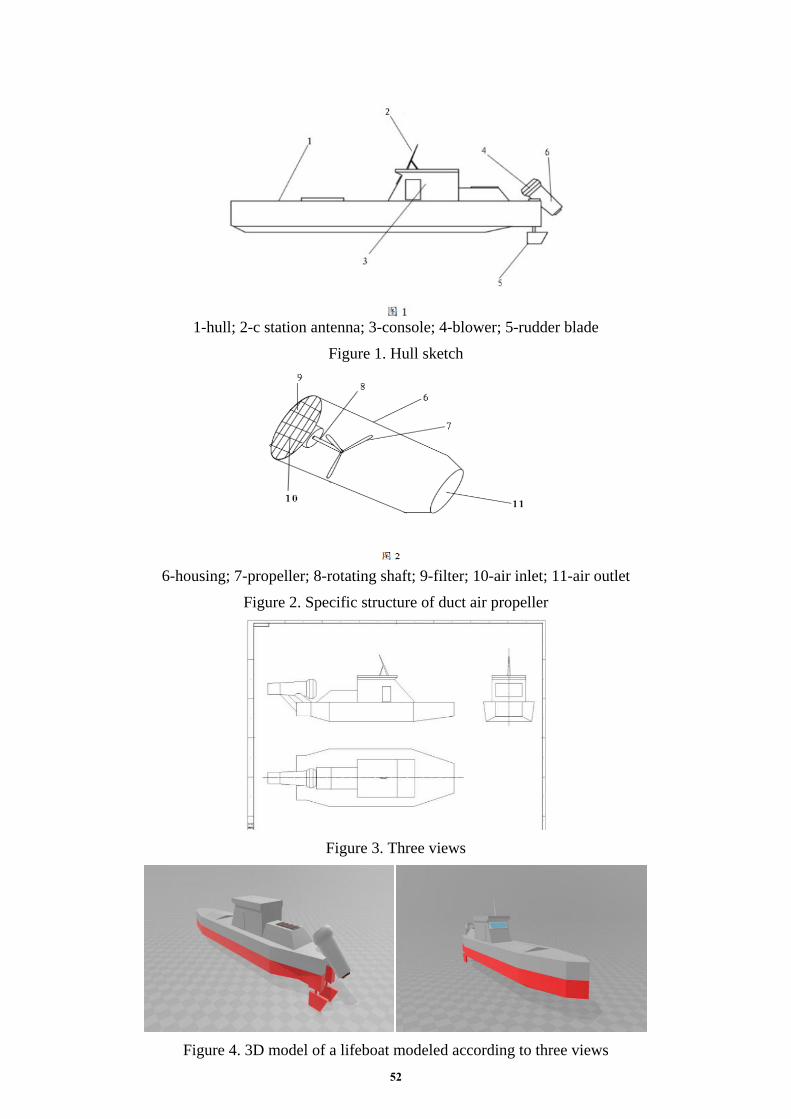
Figure 3. Three views
Figure 4. 3D model of a lifeboat modeled according to three views 52

1. Propeller diameter: 50.7mm 2. Propeller pitch: 20mm 3. Propeller thrust: 770g = 7.546N 4. Motor speed: 1200r / min 5. Hull running speed: v = 1.9737m / s 6. Hull width: 0.16m 7. Hull depth: 0.035m
Table 1. Performance criteria
performance criteria Ship speed Propeller thrust during
operation Static thrust of the ship at
start-up Ship stability
factor Calculation
results 1.8643m/s 7.327N 10.4227N 4.5714
Experimental results 1.9737m/s 7.546N 10.5381N 4.3836
The above data is calculated by formula and calculated using the actual test voyage of 1:20 model. The model hull is stable and has no defects for the time being, which verifies that the ducted air propeller lifesaving vessel is practically feasible. The theoretical entity ship speed is about 17.12 knots after calculation.
Here is the thrust change from the start of the propeller to the start of the propagation run.
Figure 5. Propeller thrust variation
5. Conclusion From the theoretical and experimental simulations, the ducted air propeller lifeboat is practical and
feasible, and can be better applied to fisheries, military and other fields in the future, which will play a certain role in ecological protection. Wetlands and inland river areas can be adapted according to demand. The improvement of local conditions has played a positive role in tourism, rescue of trapped people and other areas.
Acknowledgments This work was financially supported by Innovation and entrepreneurship training program for
college students in Dalian Ocean University in 2019 fund (provincial level, 201910158007), Liaoning Provincial Education Department's 2019 Scientific Research Funding Project (QL201911).
References [1] Wang Guoqiang, Dong Shitang, theory and application of ship propeller, second ed. Edition, Harbin University of Engineering Press, Harbin, 2007. [2] 708 Institute, hovercraft communication, 1978.
0
10
20
1 2 3 4 5 6 7 8 9 10 11 12 13
Propeller thrust variation
Simulation experiment records
Calculation record
53

[3] Duan Hong, wind turbine modeling and simulation based on momentum leaf element theory, North China Electric Power University, Beijing, 2016. [4] Zhang Yihua, Aerodynamic Numerical Simulation of horizontal axis wind turbine, Chongqing University, 2007. [5] Jiao Yuqin, Jin Chengxin, Guo Qi, experimental study on pressure fluctuation characteristics of ducted propeller, experimental fluid dynamics, Third Edition, 2008. [6] [6]Dumment R., using hovercraft in ice and water emergency rescue, Journal of Fire Engineers, 2004. [7] Code for classification and construction of high speed ships at sea, China Classification Society, people's Communications Press, Beijing, first edition, 1993 (39).
54