research article a compact multiband and dual-polarized
TRANSCRIPT

Research ArticleA Compact MultiBand and Dual-Polarized Mobile Base-StationAntenna Using Optimal Array Structure
Young-Bae Jung1 and Soon-Young Eom2
1Department of Electronics and Control Engineering, Hanbat National University, 16-1 Duckmyong-dong, Yuseong-gu,Dajeon 305-700, Republic of Korea2Radio Technology Research Department, Electronics and Telecommunications Research Institute, 138 Gajeong-no,Yuseong-gu, Dajeon 305-719, Republic of Korea
Correspondence should be addressed to Soon-Young Eom; [email protected]
Received 25 November 2014; Revised 6 March 2015; Accepted 13 March 2015
Academic Editor: Luis Landesa
Copyright © 2015 Y.-B. Jung and S.-Y. Eom. This is an open access article distributed under the Creative Commons AttributionLicense, which permits unrestricted use, distribution, and reproduction in any medium, provided the original work is properlycited.
This paper introduces a multiband base-station antenna to provide multiple communications services. There is growing need formultiband base-station antennas for mobile communications to serve existing 2nd and 3rd generation systems and to provideemerging 4th generation communication service as well as WiFi. For example, cellular, PCS, and especially WCDMA serviceare currently widely used in Korea, and 4th generation service (WiBro and LTE), introduced in 2011, will have to operate inparallel with existing services. The proposed multiband base-station antenna can provide a single/dual/triple or more multipleservices using dual-polarization (±45∘ linear polarizations) according to the requirements of the service provider. This antennahas a shared aperture, having several array antenna sets for multiple services (Band 1: cellular service in 0.824∼0.894GHz, Band2: PCS, WCDMA, and WiFi in 1.920∼2.170GHz, Band 3: WiBro and WiMAX in 2.300∼2.400GHz, and Band 4: WiMAX in5.150∼5.850GHz). This antenna can be helpful for reducing base-station operating expenses and to create a clean urban landscapeby minimizing the number of base-station antennas, which are increasing rapidly.
1. Introduction
Modern mobile communication networks are expected toaccommodate both current and legacy communications stan-dards.This inevitably involves the provision of radio coveragein a number of frequency bands and complicates the designof the network base transceiver stations (BTS). With respectto antennas, the expense of multiple base-station antennainstallations and public resistance to unsightly antenna place-ments has motivated the installation of multiband antennasat base-stations and thus avoids an increase of antenna mastsand payloads. Multiband antennas are usually expected todemonstrate comparable performance measures (especiallyinput impedance, radiation pattern, and polarization) in eachof their operating bands and have been the subject of vigorousresearch over the past two decades [1].
Significant advances have been made in designing anten-nas with sufficient bandwidth in two or even three dif-ferent bands using multiresonance and operating band
reconfigurable techniques [2–14]. For the most part, thisresearch has been concerned with the design of isolatedmultiband elements, and relatively little work has been doneto address the problems inherent in multiband array design[15, 16]. In particular, the element geometry and layout ofmultiband arrays must be carefully chosen to avoid theappearance of grating lobes in the radiation pattern. Base-station antenna arrays present further challenges in thatthey require shaped radiation patterns to limit intersiteinterference andmust satisfy very low intermodulation limits[1].
Most studies on multiband antennas, however, have thusfar focused on applications for mobile terminals that canbe operated at low power. For the base-station, multibandantennas mainly have been researched by antenna manufac-turers, and recently some major antenna manufacturers haveintroduced triple-band models. As the number of servicesincreases, many additional base-station antennas and infras-tructure should be installed for new services. In addition
Hindawi Publishing CorporationInternational Journal of Antennas and PropagationVolume 2015, Article ID 178245, 11 pageshttp://dx.doi.org/10.1155/2015/178245
2 International Journal of Antennas and Propagation
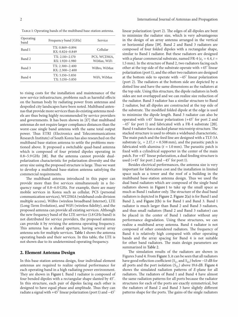
Table 1: Operating bands of the multiband base-station antenna.
Operatingband Frequency band [GHz] Service
Band 1 TX: 0.869∼0.894RX: 0.824∼0.849 Cellular
Band 2 TX: 2.110∼2.170RX: 1.920∼1.980
PCS, WCDMA,WiMax, WiFi
Band 3 TX: 2.300∼2.400RX: 2.300∼2.400 WiBro, WiMax
Band 4 TX: 5.150∼5.850TX: 5.150∼5.850 WiFi, WiMax
to rising costs for the installation and maintenance of thenew service infrastructure, problems such as harmful effectson the human body by radiating power from antennas anddespoiled city landscapes have been noted. Multiband anten-nas that providemore services than do existing antennamod-els are thus being highly recommended by service providersand governments. It has been shown in [17] that multibandantennas do not require larger compliance distances than theworst-case single band antenna with the same total outputpower. Thus ETRI (Electronics and TelecommunicationsResearch Institute) of South Korea has also researched on themultiband base-station antenna to settle the problems men-tioned above. It proposed a switchable quad-band antennawhich is composed of four printed dipoles operating in0.8∼5.9GHz [18]. But the antenna cannot provide dual-polarization characteristic for polarization diversity and thearray size using the proposed structure is large.Thus we wantto develop a multiband base-station antenna satisfying thecommercial requirements.
The multiband antenna introduced in this paper canprovide more than five services simultaneously in a fre-quency range of 0.8∼6.0GHz. For example, there are manymobile services in Korea such as cellular, PCS (personalcommunication services),WCDMA(wideband code divisionmultiple access), WiBro (wireless broadband Internet), LTE(Long-Term Evolution), and WiFi (wireless fidelity), and theproposed antenna can provide all existing services. Althoughthe new frequency band of the LTE service (1.8 GHz band) isnot distributed for service providers, the proposed antennacan provide it by revising the antenna operating frequency.This antenna has a shared aperture, having several arrayantenna sets for multiple services. Table 1 shows the antennaoperating bands and their services. In this table, the LTE isnot shown due to its undetermined operating frequency.
2. Element Antenna Design
In this base-station antenna design, four individual elementantennas are required to realize optimal performance foreach operating band in a high radiating power environment.They are shown in Figure 1. Band 1 radiator is composed offour bended dipoles with a rectangular shape slanted by 45∘.In this structure, each pair of dipoles facing each other isdesigned to have equal phase and amplitude. Thus they canradiate a signal with +45∘ linear polarization (port 1) and−45∘
linear polarization (port 2). The edges of all dipoles are bentto minimize the radiator size, which is very advantageousin the design of an array antenna arranged in the verticalor horizontal plane [19]. Band 2 and Band 3 radiators arecomposed of four folded dipoles with a rectangular shape,similar to Band 1 radiator. But these radiators are designedwith a planar commercial substrate, named FR-4 (𝜀
𝑟= 4.4, 𝑡 =
1.5mm). In the structure of Band 2, two radiators facing eachother at the top side of the substrate operate with +45∘ linearpolarization (port 1), and the other two radiators are designedat the bottom side to operate with −45∘ linear polarization(port 2). The radiators at the bottom side are depicted by adotted line and have the same dimensions as the radiators atthe top side. Using this structure, the dipole radiators in bothsides are not overlapped and we can realize size reduction ofthe radiator. Band 3 radiator has a similar structure to Band2 radiator, but all dipoles are constructed at the top side ofthe substrate. The modified folded dipole at the edge is usedto minimize the dipole length. Band 3 radiator can also beoperated with ±45∘ linear polarization (+45∘ for port 2 and−45∘ for port 1) and fabricated with a FR-4 substrate [20].Band 4 radiator has a stacked planarmicrostrip structure.Thestacked structure is used to obtain a wideband characteristic.The main patch and the feed line are designed with a TLY-5Asubstrate (𝜀
𝑟= 2.17, 𝑡 = 0.508mm), and the parasitic patch is
fabricated with alumina (𝑡 = 1.0mm). The parasitic patch isfixed with a cylindrical supporter in the center of the mainpatch. For +45∘ linear polarization, a dual feeding structure isused (+45∘ for port 2 and −45∘ for port 1).
Besides electrical performances, the antenna size is veryimportant for fabrication cost and the installation in limitedspace such as a tower and the roof of a building in themultiband base-station antenna design. Thus we used thedual band radiators which are composed of the single bandradiators shown in Figure 1 to take up the small space asmuch as Band 1 radiator only. The structure of the dual bandradiators is depicted in Figure 2. Figure 2(a) is for Band 1 andBand 2, and Figure 2(b) is for Band 1 and Band 3. Band 1radiator is much larger than Band 2 and Band 3 radiators,and thus small radiators (Band 2 and Band 3 radiator) canbe placed in the center of Band 1 radiator without anyperformance degradation. Using these structures, we canrealize a multiband array antenna. Band 4 radiator is notcomposed of other considered radiators. The frequency ofBand 4 is relatively high compared with other operatingbands and the array spacing for Band 4 is not suitablefor other band radiators. The main design parameters aresummarized in Table 2.
The simulation results of the radiators are shown inFigures 3 and 4. FromFigure 3, it can be seen that all radiatorshave good reflection coefficient (S
11and S22) below−13 dB for
all ports and the port isolation (S21) above 19.6 dB. Figure 4
shows the simulated radiation patterns of 𝐸-plane for allradiators. The radiators of Band 1 and Band 4 have almostthe same radiation patterns for all ports because the radiatorstructures for each of the ports are exactly symmetrical, butthe radiators of Band 2 and Band 3 have slightly differentpatterns shape for the ports. The gains of the single radiators

International Journal of Antennas and Propagation 3
Table 2: Main design parameters of element antennas [unit: mm].
Mark Value Mark Value Mark Value Mark Value Mark Value Mark ValueS1 160.5 L1 109.5 W1 21 D1 173.7 T1 1.5 H1 60S2 68 L2 43 W2 5.8 D2 87 T2 1.5 H2 39S3 59 L3 42 W3 6 D3 72 T3 1.5 H3 36.5
L4 22 D4 31.1 T4 1.0 H4 4.5L5 16 D5 22.6 T5 0.508
Metal rod dipole
Supporter (alumina)
Port 1 Port 2
S1L1
W1
D1T1
H1
(a)
Printed dipoleon FR4
Printed dipole (back-side)
Port 1 Port 2
Supporter (alumina)
S2L2
W2
D2T2
H2
(b)
Printed dipoleon FR4
Port 1 Port 2
Supporter (alumina)
W3
S3L3
D3
T3
H3
(c)
Parasitic radiator (metal plate)
Printed patchon TLY-5A
Port 1 Port 2
Supporter (alumina)
L4L5
D4D5
T4H4
T5
(d)
Figure 1: Single band radiator structure: (a) Band 1, (b) Band 2, (c) Band 3, and (d) Band 4 (up: top view, down: side view, and large arrow:direction of side view).

4 International Journal of Antennas and Propagation
Band 2 radiator
Band 1 radiatorS1
S2
H1H2
D1
D2
Band 2Band 1
(a)
Band 3 radiator
Band 1 radiator
H1H2
D1
D2
S1S3
Band 1 Band 3
(b)
Figure 2: Dual band radiator structure: (a) Band 1 + Band 2; (b) Band 1 + Band 3 (up: top view, down: side view, and large arrow: directionof side view).
are 7.1 dBi, 6.4 dBi, 6.2 dBi, and 6.7 dBi for Band 1, Band 2,Band 3, and Band 4, respectively.
3. Multiband Array Antenna Design
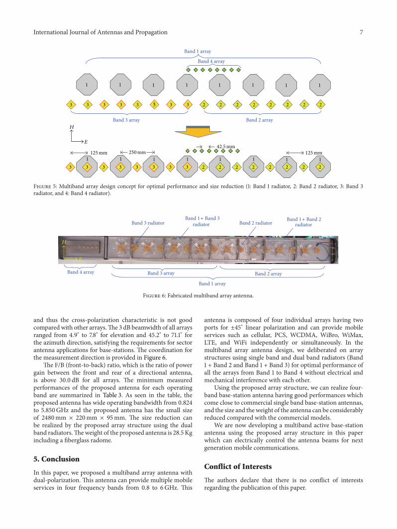
In the multiband array antenna design, it is imperativethat all the arrays from Band 1 to Band 4 provide optimalperformance without electrical and mechanical interferencewith each other.We thus deliberated on array structures usingsingle band and dual band radiators and analyzed the arrayspacing for all bands. As mentioned above, the frequency ofBand 1 is the lowest of the studied operating bands, whileBand 2 and Band 3 have similar frequencies separated by only210MHz. Band 4 has a high frequency compared with theother bands. Taking into consideration the wavelength of allbands at the center frequency, we can arrange all arrays tocomprise 8 elements, as shown in the top half of Figure 5:
Band 1: (TX) center frequency = 0.881 GHz (𝜆0=
340.3mm),(RX) center frequency = 0.837GHz (𝜆
0= 358.6mm);
Band 2: (TX) center frequency = 2.140GHz (𝜆0=
140.2mm),(RX) center frequency = 1.950GHz (𝜆
0= 153.8mm);
Band 3: (TX) center frequency = 2.350GHz (𝜆0=
127.7mm),(RX) center frequency = 2.350GHz (𝜆
0= 127.7mm);
Band 4: (TX) center frequency = 5.500GHz (𝜆0=
54.5mm),(RX) center frequency = 5.500GHz (𝜆
0= 54.5mm).
For grating lobe suppression, we want to design all arrayswith minimum array spacing below 1.0𝜆
0[21]. First, we
designed Band 1 array with array spacing from 0.70𝜆0to
1.0𝜆0considering the radiator size. To minimize the entire
antenna size, it is very helpful to use multiband radiators, asdepicted in Figure 2, for space sharing. We used eight dualband radiators at both sides of the multiband array, and fourof these radiators are for “Band 1 + Band 2” and the othersare for “Band 1 + Band 3.” In addition, four single bandradiators for “Band 2 and Band 3” are placed between the dualband radiators, as shown in the lower diagram of Figure 5.Thus we could realize a composite array structure with threeindividual radiators. In Figure 5, Band 2 array is placed in theleft half of the multiband array structure, and Band 3 arrayis in the right half of the structure. Using this configuration,we can realize a triple-band array antenna within the size of asingle band array for Band 1. Band 4 radiator is much smallerthan the other radiators and the array spacing is very close inthe aspect of electrical wavelength. If Band 4 array is designedwith other radiators, interference with other large radiators ispossible, which can block the radiation of Band 4 radiator.Band 4 array was thus designed separately from the otherband arrays:
Band 1: spacing = 250mm (TX: 0.73𝜆0, RX: 0.70𝜆
0);
Band 2: spacing = 125mm (TX: 0.90𝜆0, RX: 0.81𝜆
0);
Band 3: spacing = 125mm (TX: 0.98𝜆0, RX: 0.98𝜆
0);
Band 4: spacing = 42.5mm (TX: 0.78𝜆0, RX: 0.78𝜆
0).
For the array of “Band 2 and Band 3,” the final arrayspacing is 125mm, which was decided by a performanceanalysis according to the array spacing. The array spacingexceeding 125mm makes SLL (Side-Lobe Level) of Band 3array degraded by a grating lobe, while the spacing below125mmmakes the interference among the radiators increase.The array spacing of 125mm is 0.90𝜆
0for TX and 0.81𝜆
0for

International Journal of Antennas and Propagation 5
0
−10
−20
−30
−40
0.82 0.83 0.84 0.85 0.86 0.87 0.88 0.89 0.90
Frequency (GHz)
Refle
ctio
n co
effici
ent (
dB)
(a)
Frequency (GHz)
0
−10
−20
−30
−40
Refle
ctio
n co
effici
ent (
dB)
1.90 1.95 2.00 2.05 2.10 2.15 2.20
(b)
Frequency (GHz)
0
−10
−20
−30
−40
Refle
ctio
n co
effici
ent (
dB)
2.28 2.30 2.32 2.34 2.36 2.38 2.40
S11
S21
S22
(c)
Frequency (GHz)
0
−10
−20
−30
−40
Refle
ctio
n co
effici
ent (
dB)
5.0 5.2 5.4 5.6 5.8 6.0
S11
S21
S22
(d)
Figure 3: Simulated reflection coefficient and isolation characteristic of the radiators: (a) Band 1, (b) Band 2, (c) Band 3, and (d) Band 4.
RX, and the spacing for Band 3 is 0.98𝜆0for TX and RX.Thus
Band 1 array is designedwith array spacing of 250mm(0.73𝜆0
for TX and 0.70𝜆0for RX). Band 4 array is designed with
array spacing of 42.5mm, which is 0.78𝜆0for TX and RX.
4. Fabrication and Performance Test
Figure 6 shows the photo of the fabricatedmultiband antennahaving the array antenna design concept depicted in Figure 5and the photos of the fabricated radiators used in themultiband array antenna are shown in Figure 7. Figures 7(a)and 7(b) present the dual band radiators shown in Figure 6.The dipoles of Band 1 radiator are fabricated with a metal rodhaving a radius of 2mm, and we combined the dipoles withalumina supporters using screws. Finally, assembled Band 1radiator is fixed in an antenna ground plane with screws, andRF cables are directly connected to the feeding point at thebottom side of the radiator. The feeding points are marked
with bold dashed circles in the top views of Figure 1. For Band2 and Band 3 radiators, an alumina supporter is first fixedin the ground plane using screws and the printed dipolesare connected on the top side of the supporter. RF cablesare connected to the feeding point at the bottom side of theradiators also. Figure 7(c) shows fabricated Band 4 radiator.The square patch shown in this photo is the alumina parasiticradiator and the main square patch which is designed witha commercial substrate is situated under the parasitic patch.The main patch is fixed in the ground plane, and a parasiticpatch having a cylindrical supporter is assembled at the centerof the main patch with a long screw.
A performance test of the fabricated antenna was per-formed. First, the return loss and isolation characteristicswere tested.The isolation characteristics are especially impor-tant because all radiators can provide dual-polarization of±45∘ using dual-ports and we can realize the other linear andcircular polarizations by using the phase control circuit in

6 International Journal of Antennas and Propagation
10
0
−10
−20
−30
−40
Gai
n (d
Bi)
−180
−150
−120
−90
−60
−30 0
30
60
90
120
150
180
Angle (deg)
(a)
10
0
−10
−20
−30
−40
Gai
n (d
Bi)
−180
−150
−120
−90
−60
−30 0
30
60
90
120
150
180
Angle (deg)
(b)
10
0
−10
−20
−30
−40
Gai
n (d
Bi)
−180
−150
−120
−90
−60
−30 0
30
60
90
120
150
180
Angle (deg)Port 1Port 2
(c)
10
0
−10
−20
−30
−40
Gai
n (d
Bi)
−180
−150
−120
−90
−60
−30 0
30
60
90
120
150
180
Angle (deg)Port 1Port 2
(d)
Figure 4: Simulated radiation patterns of the radiators of 𝐸-plane: (a) 0.881 GHz for Band 1, (b) 2.14GHz for Band 2, (c) 2.35GHz for Band3, and (d) 5.5 GHz for Band 4.
the feed network. All measured results for the arrays of eachband are shown in Figure 8. Band 1 array has return loss (S
11
and S22) below −20 dB for all ports and the isolation (S
21)
between the ports is below −18.5 dB from 0.824 to 0.894GHz.The measured frequency includes both TX and RX bands.Band 2 array has return loss below −19.5 dB for all ports andthe isolation is below −32 dB from 1.92 to 2.17GHz. For Band3 array, the minimum return loss and isolation are −20 dBand −33 dB, respectively, for an operating band from 2.30to 2.40GHz. Band 4 array has return loss below −10.2 dBand isolation below −14.5 dB. Because Band 4 radiator hasa dual-port per single radiator, it is relatively more sensitivethan the single feeding structure in terms of its returnloss and isolation characteristics. A radiation pattern test ofthe fabricated antenna was performed in a compact rangechamber and far-field range anechoic chamber of Orbit Inc.with the cooperation of ACE Technology Inc. All measuredradiation patterns are depicted in Figure 9. The radiation
patterns measured at the center frequency of the TX and RXbands for Band 1 and Band 2 are shown from Figures 9(a)–9(d). The radiation patterns of Band 3 and Band 4 are shownfrom Figures 9(e)–9(h) at the start and the center frequencybecause the TX and RX operating frequency are the same.From the results at the center frequencies, Band 1 array hasthe gain of 17.4 dBi and 17.1 dBi for the cross-polarizationcharacteristic of 24.5 dB and 25.0 dB with SLL of 12.5 dB and12.6 dB, for RX and TX, respectively.The gain of Band 2 arrayis 17.2 dBi for TX and 16.6 dBi for RX. The SLL is 12.2 dB and13.7 dB and the cross-polarization characteristic is 26.8 dBand 27.2 dB, for RX and TX, respectively. For Band 3 array,the minimum gain is 16.6, the SLL is 11.6 dB, and the cross-polarization is 32.5 dB. Band 4 has a gain of 14.0 dBi with aSLL of about 11.8 dB.
The minimum value of cross-polarization is 15.0 dB. Asmentioned above, Band 4 radiator has a commonpatch struc-ture with dual-ports having inherent sensitive port isolation,
International Journal of Antennas and Propagation 7
2 2
1 1 1 1 1 1 1 1
2 2 2 2223 33 3 3 333
Band 1 array
Band 3 array Band 2 array
1 1 1 1 1 1 1 12 22 2 2 2223 33 3 3 333
Band 4 array
E
250mm125mm 125mm42.5mm
H
Figure 5: Multiband array design concept for optimal performance and size reduction (1: Band 1 radiator, 2: Band 2 radiator, 3: Band 3radiator, and 4: Band 4 radiator).
Band 2 arrayBand 4 array
radiator
Band 3 array
radiatorBand 3 radiator Band 2 radiator
Band 1 array
E
H
Band 1+ Band 3 Band 1+ Band 2
Figure 6: Fabricated multiband array antenna.
and thus the cross-polarization characteristic is not goodcompared with other arrays.The 3 dB beamwidth of all arraysranged from 4.9∘ to 7.8∘ for elevation and 45.2∘ to 71.1∘ forthe azimuth direction, satisfying the requirements for sectorantenna applications for base-stations. The coordination forthe measurement direction is provided in Figure 6.
The F/B (front-to-back) ratio, which is the ratio of powergain between the front and rear of a directional antenna,is above 30.0 dB for all arrays. The minimum measuredperformances of the proposed antenna for each operatingband are summarized in Table 3. As seen in the table, theproposed antenna has wide operating bandwidth from 0.824to 5.850GHz and the proposed antenna has the small sizeof 2480mm × 220mm × 95mm. The size reduction canbe realized by the proposed array structure using the dualband radiators.Theweight of the proposed antenna is 28.5 Kgincluding a fiberglass radome.
5. Conclusion
In this paper, we proposed a multiband array antenna withdual-polarization. This antenna can provide multiple mobileservices in four frequency bands from 0.8 to 6GHz. This
antenna is composed of four individual arrays having twoports for ±45∘ linear polarization and can provide mobileservices such as cellular, PCS, WCDMA, WiBro, WiMax,LTE, and WiFi independently or simultaneously. In themultiband array antenna design, we deliberated on arraystructures using single band and dual band radiators (Band1 + Band 2 and Band 1 + Band 3) for optimal performance ofall the arrays from Band 1 to Band 4 without electrical andmechanical interference with each other.
Using the proposed array structure, we can realize four-band base-station antenna having good performances whichcome close to commercial single band base-station antennas,and the size and theweight of the antenna can be considerablyreduced compared with the commercial models.
We are now developing a multiband active base-stationantenna using the proposed array structure in this paperwhich can electrically control the antenna beams for nextgeneration mobile communications.
Conflict of Interests
The authors declare that there is no conflict of interestsregarding the publication of this paper.

8 International Journal of Antennas and Propagation
(a) (b) (c)
Figure 7: Top view of fabricated radiators for multiband base-station antenna: (a) Band 1 + Band 2, (b) Band 1 + Band 3, and (c) Band 4.
0
−10
−20
−30
−40
0.82 0.83 0.84 0.85 0.86 0.87 0.88 0.89 0.90
Frequency (GHz)
Refle
ctio
n co
effici
ent (
dB)
(a)
Frequency (GHz)
0
−10
−20
−30
−40
Refle
ctio
n co
effici
ent (
dB)
1.90 1.95 2.00 2.05 2.10 2.15 2.20
(b)
Frequency (GHz)
0
−10
−20
−30
−40
Refle
ctio
n co
effici
ent (
dB)
2.28 2.30 2.32 2.34 2.36 2.38 2.40
S11
S21
S22
(c)
Frequency (GHz)
0
−10
−20
−30
−40
Refle
ctio
n co
effici
ent (
dB)
5.0 5.2 5.4 5.6 5.8 6.0
S11
S21
S22
(d)
Figure 8: Measured return loss and isolation characteristic of the multiband array: (a) Band 1, (b) Band 2, (c) Band 3, and (d) Band 4.

International Journal of Antennas and Propagation 9
Gai
n (d
Bi)
−180
−150
−120
−90
−60
−30 0
30
60
90
120
150
180
Angle (deg)
20
15
10
5
0
−5
−10
−15
−20
−25
−30
−35
−40
Co-pol @ H-planeCo-pol @ E-plane
X-pol @ H-planeX-pol @ E-plane
(a)
Gai
n (d
Bi)
−180
−150
−120
−90
−60
−30 0
30
60
90
120
150
180
Angle (deg)
20
15
10
5
0
−5
−10
−15
−20
−25
−30
−35
−40
Co-pol @ H-planeCo-pol @ E-plane
X-pol @ H-planeX-pol @ E-plane
(b)
Gai
n (d
Bi)
−180
−150
−120
−90
−60
−30 0
30
60
90
120
150
180
20
15
10
5
0
−5
−10
−15
−20
−25
−30
−35
−40
Angle (deg)Co-pol @ H-planeCo-pol @ E-plane
X-pol @ H-planeX-pol @ E-plane
(c)
Gai
n (d
Bi)
−180
−150
−120
−90
−60
−30 0
30
60
90
120
150
180
20
15
10
5
0
−5
−10
−15
−20
−25
−30
−35
−40
Angle (deg)Co-pol @ H-planeCo-pol @ E-plane
X-pol @ H-planeX-pol @ E-plane
(d)
Gai
n (d
Bi)
−180
−150
−120
−90
−60
−30 0
30
60
90
120
150
180
20
15
10
5
0
−5
−10
−15
−20
−25
−30
−35
−40
Angle (deg)Co-pol @ H-planeCo-pol @ E-plane
X-pol @ H-planeX-pol @ E-plane
(e)
Gai
n (d
Bi)
−180
−150
−120
−90
−60
−30 0
30
60
90
120
150
180
20
15
10
5
0
−5
−10
−15
−20
−25
−30
−35
−40
Angle (deg)Co-pol @ H-planeCo-pol @ E-plane
X-pol @ H-planeX-pol @ E-plane
(f)
Figure 9: Continued.

10 International Journal of Antennas and Propagation
Gai
n (d
Bi)
−180
−150
−120
−90
−60
−30 0
30
60
90
120
150
180
20
15
10
5
0
−5
−10
−15
−20
−25
−30
−35
−40
Angle (deg)Co-pol @ H-planeCo-pol @ E-plane
X-pol @ H-planeX-pol @ E-plane
(g)
Gai
n (d
Bi)
−180
−150
−120
−90
−60
−30 0
30
60
90
120
150
180
20
15
10
5
0
−5
−10
−15
−20
−25
−30
−35
−40
Angle (deg)Co-pol @ H-planeCo-pol @ E-plane
X-pol @ H-planeX-pol @ E-plane
(h)
Figure 9: Measured radiation patterns of the multiband array: (a) 0.881 GHz for TX of Band 1, (b) 0.837GHz for RX of Band 1, (c) 2.14GHzfor TX of Band 2, (d) 1.95GHz for RX of Band 2, (e) 2.30GHz for Band 3, (f) 2.35GHz for Band 3, (g) 5.15 GHz for Band 4, and (h) 5.50GHzfor Band 4.
Table 3: Summary of minimum measured performances of the multiband base-station antenna.
Operating band Gain [dBi] SLL [dB] BW (El) [∘] BW (Az) [∘] Cross-pol. [dB] F/B ratio [dB] Size [mm]/weight [Kg]Band 1
TX 17.1 12.2 7.0 63.8 24.5 30.2
2480 (L) × 220 (W) × 95 (H)/28.5
RX 17.0 12.3 7.8 64.7 25.0 31.8Band 2
TX 17.0 12.0 5.0 47.5 26.4 30.2RX 16.3 13.7 5.5 50.4 25.4 32.7
Band 3T/RX 16.6 10.1 4.9 45.2 31.8 32.5
Band 4T/RX 14.0 11.8 6.5 71.1 15.0 35.4
∗SLL: Side-Lobe Level, BW: 3-dB beamwidth, and F/B: front-to-back.
Acknowledgments
The authors would like to express their gratitude to Y. H. Leeand other members of ACE Antenna Inc. for their valuableadvice and contributions to the antenna development. Thisresearch was supported by the MSIP (Ministry of Science,ICT and Future Planning), Korea, under the Global IT TalentSupport Program (NIPA-2014-H0904-14-1002) supervised bythe NIPA (National IT Industry Promotion Agency) and theresearch fund of Hanbat National University in 2013.
References
[1] P. L. Starke and G. G. Cook, “Optimised design of multi-band cellular base station antenna array for GSM and UMTSdeployment,” IET Microwaves, Antennas & Propagation, vol. 3,no. 2, pp. 333–347, 2009.
[2] N. Chiba, T. Amano, and H. Iwasaki, “Dual-frequency planarantenna for handsets,” Electronics Letters, vol. 34, no. 25, pp.2362–2363, 1998.
[3] Z. D. Liu and P. S. Hall, “Dual-band antenna for hand heldportable telephones,” Electronics Letters, vol. 32, no. 7, pp. 609–610, 1996.
[4] S. D. Targonski and D. M. Pozar, “Dual-band dual polarisedprinted antenna element,” Electronics Letters, vol. 34, no. 23, pp.2193–2194, 1998.
[5] F. J. Villegas, T. Cwik, Y. Rahmat-Samii, and M. Manteghi, “Aparallel electromagnetic genetic-algorithm optimization (ego)application for patch antenna design,” IEEE Transactions onAntennas and Propagation, vol. 52, no. 9, pp. 2424–2435, 2004.
[6] H. F. Abutarboush, R. Nilavalan, S. W. Cheung et al., “Areconfigurable wideband and multiband antenna using dual-patch elements for compact wireless devices,” IEEETransactionson Antennas and Propagation, vol. 60, no. 1, pp. 36–43, 2012.
[7] M. T. Islam, M. N. Shakib, and N. Misran, “Design analysisof high gain wideband L-probe fed microstrip patch antenna,”Progress in Electromagnetics Research, vol. 95, pp. 397–407, 2009.
[8] S. Lee and Y. Sung, “A compact triple band antenna for awireless USB dongle,” Journal of Electromagnetic Engineeringand Science, vol. 12, no. 2, pp. 185–188, 2012.
International Journal of Antennas and Propagation 11
[9] D. Piazza, N. J. Kirsch, A. Forenza, R. W. Heath, and K. R.Dandekar, “Design and evaluation of a reconfigurable antennaarray for MIMO systems,” IEEE Transactions on Antennas andPropagation, vol. 56, no. 3, pp. 869–881, 2008.
[10] J.-W. Baik, S. Pyo, T.-H. Lee, and Y.-S. Kim, “Switchable printedYagi-Uda antenna with pattern reconfiguration,” ETRI Journal,vol. 31, no. 3, pp. 318–320, 2009.
[11] Y.-C. Lee and J.-S. Sun, “Compact printed slot antennas forwireless dual- and multi-band operations,” Progress in Electro-magnetics Research, vol. 88, pp. 289–305, 2008.
[12] W.H.Weedon,W. J. Payne, andG.M. Rebeiz, “MEMS-switchedreconfigurable antennas,” in Proceedings of the IEEE Antennasand Propagation Society International Symposium, vol. 3, pp.654–657, IEEE, Boston, Mass, USA, July 2001.
[13] C. won Jung, M. J. Lee, G. P. Li, and F. de Flaviis, “Reconfig-urable scan-beam single-arm spiral antenna integratedwithRF-MEMS switches,” IEEE Transactions on Antennas and Propaga-tion, vol. 54, no. 2, pp. 455–463, 2006.
[14] Z.N.Chen, “Development of ultra-wideband antennas,” Journalof Electromagnetic Engineering and Science, vol. 13, no. 2, pp. 63–72, 2013.
[15] D. M. Pozar and S. D. Targonski, “A shared-aperture dual-band dual-polarized microstrip array,” IEEE Transactions onAntennas and Propagation, vol. 49, no. 2, pp. 150–157, 2001.
[16] N. Herscovici, C. Christodoulou, Z. Zaharis, E. Vafiadis, andJ. N. Sahalos, “On the design of a dual-band base station wireantenna,” IEEEAntennas and PropagationMagazine, vol. 42, no.6, pp. 144–151, 2000.
[17] A. Thielens, G. Vermeeren, D. Kurup, W. Joseph, and L.Martens, “Compliance boundaries for multiple-frequency basestation antennas in three directions,” Bioelectromagnetics, vol.34, no. 6, pp. 465–478, 2013.
[18] T.Wu, R. L. Li, S. Y. Eom et al., “Switchable quad-band antennasfor cognitive radio base station applications,” IEEE Transactionson Antennas and Propagation, vol. 58, no. 5, pp. 1468–1476, 2010.
[19] R. Gabriel and M. Gottl, “Dual-polarized Dipole Antenna,”United States Patent US 6,313,809, 2001.
[20] J. S. Park and J. S. Jin, “Dual polarization broadbandantenna having with single pattern,” International ApplicationPCT/KR2007/001597, 2007.
[21] T. Suda, T. Takano, and Y. Kazama, “Grating lobe suppressionin an array antenna with element spacing greater than ahalf wavelength,” in Proceedings of the IEEE Antennas andPropagation Society International Symposium (APSURSI ’10), pp.1–4, Toronto, Canada, July 2010.

International Journal of
AerospaceEngineeringHindawi Publishing Corporationhttp://www.hindawi.com Volume 2014
RoboticsJournal of
Hindawi Publishing Corporationhttp://www.hindawi.com Volume 2014
Hindawi Publishing Corporationhttp://www.hindawi.com Volume 2014
Active and Passive Electronic Components
Control Scienceand Engineering
Journal of
Hindawi Publishing Corporationhttp://www.hindawi.com Volume 2014
International Journal of
RotatingMachinery
Hindawi Publishing Corporationhttp://www.hindawi.com Volume 2014
Hindawi Publishing Corporation http://www.hindawi.com
Journal ofEngineeringVolume 2014
Submit your manuscripts athttp://www.hindawi.com
VLSI Design
Hindawi Publishing Corporationhttp://www.hindawi.com Volume 2014
Hindawi Publishing Corporationhttp://www.hindawi.com Volume 2014
Shock and Vibration
Hindawi Publishing Corporationhttp://www.hindawi.com Volume 2014
Civil EngineeringAdvances in
Acoustics and VibrationAdvances in
Hindawi Publishing Corporationhttp://www.hindawi.com Volume 2014
Hindawi Publishing Corporationhttp://www.hindawi.com Volume 2014
Electrical and Computer Engineering
Journal of
Advances inOptoElectronics
Hindawi Publishing Corporation http://www.hindawi.com
Volume 2014
The Scientific World JournalHindawi Publishing Corporation http://www.hindawi.com Volume 2014
SensorsJournal of
Hindawi Publishing Corporationhttp://www.hindawi.com Volume 2014
Modelling & Simulation in EngineeringHindawi Publishing Corporation http://www.hindawi.com Volume 2014
Hindawi Publishing Corporationhttp://www.hindawi.com Volume 2014
Chemical EngineeringInternational Journal of Antennas and
Propagation
International Journal of
Hindawi Publishing Corporationhttp://www.hindawi.com Volume 2014
Hindawi Publishing Corporationhttp://www.hindawi.com Volume 2014
Navigation and Observation
International Journal of
Hindawi Publishing Corporationhttp://www.hindawi.com Volume 2014
DistributedSensor Networks
International Journal of