research article a lower extremity exoskeleton: human
TRANSCRIPT
Research ArticleA Lower Extremity Exoskeleton Human-MachineCoupled Modeling Robust Control Design Simulation andOverload-Carrying Experiment
Qing Guo1 Songjing Li2 and Dan Jiang3
1School of Aeronautics and Astronautics University of Electronic Science and Technology of China Chengdu 611731 China2Department of Fluid Control amp Automation Harbin Institute of Technology Harbin 150001 China3School of Mechatronics Engineering University of Electronic Science and Technology of China Chengdu 611731 China
Correspondence should be addressed to Qing Guo guoqinguestc163com
Received 4 November 2014 Revised 8 May 2015 Accepted 10 May 2015
Academic Editor Stanisław Migorski
Copyright copy 2015 Qing Guo et alThis is an open access article distributed under theCreativeCommonsAttributionLicense whichpermits unrestricted use distribution and reproduction in any medium provided the original work is properly cited
A robust 119867infin
control method and switched control algorithm for hydraulic actuator presents in human-machine coordinatedmotion to solve the motion delay of lower extremity exoskeleton After the characteristic parameters synthesis of human limband exoskeleton linkage the human-machine coupled motion model is constructed to estimate the appropriate hydraulic pressurewhich is considered as a structural uncertainty in hydraulic model Then the robust controller is designed to improve the robuststability and performance under the structural and parametric uncertainty disturbances Simulation results show that in walkingmode this robust controller can achieve a better dynamic response and aid-force efficiency than PID controller Then accordingto gait divisions of personrsquos limb motion the switched control algorithm is designed to reduce the delay of exoskeleton trackingperson Finally the experimental results show that the human-machine coordinated walk with bearing 60 kg load and squat actionwith no external load are realized effectively by this proposed method
1 Introduction
Lower extremity exoskeleton is a humanoid mechanicalequipment Since the exoskeleton can help a person bearmany loads and track a personrsquos motion the soldierrsquos loadcapacity and flexibility can be significantly improved Theexoskeleton is a complex system including 4 subsystemsmechanical structure gait sensing hydraulic control andpower supply Recently lower extremity exoskeleton can bearthe maximum load 200 lbs and realize typical action suchas walk running up and down hill or stairs squatting andtrotting [1] Since 2000 DARPA and U C Berkeley havedone many researches on exoskeleton and developed theprototypes called ldquoXOSrdquo and ldquoBLEEXrdquo [2ndash4] respectivelyLockheed has simplified the hydraulic actuator amountof BLEEX and renamed ldquoHuman Universal Load Carrierrdquo(HULC) [1] Other countries like Japan and France havedeveloped commercial or military exoskeleton called ldquoHALrdquoor ldquoHerculerdquo [5] In 2000 Atkeson et al [6] made conclusions
on the characteristics of humanoid robot sometimes themotion of machine is guided by person sometimes just theopposite especially sometimes the boundary is not clearlydivided between the two Due to the personrsquos participationthe traditional robotic program controlmethodwill cause themotional delay of exoskeleton tracking person [7]
Since 2004 the exoskeleton technology is developed inChina [8] A motor-driven exoskeleton with no external loadis designed by Naval Aeronautical Engineering Institute [9]In addition the aid-force exoskeleton with hydraulic-drivenactuator is designed to realize walk up and down stairs[10] However the human-machine coordinated motion isnot presented in aforementioned references if personrsquos gaitcharacteristic is ignored in exoskeleton control personrsquoscomfort and the aid-force effect are reduced In this paper ahuman-machine coupled model is constructed to analyze thedynamic external load This external load describes the aid-force efficiency of exoskeleton in the case of personrsquos safetyand should be compensated by exoskeleton controller
Hindawi Publishing CorporationMathematical Problems in EngineeringVolume 2015 Article ID 905761 15 pageshttpdxdoiorg1011552015905761
2 Mathematical Problems in Engineering
Due to the demands of high load efficiency and fastresponse lower extremity exoskeleton is driven by theelectrohydraulic servo system (EHSS) However EHSS hassome model uncertainties such as parametric disturbancesstructural uncertainties which are consequences of hydraulicphysical characteristics oil leakage oil temperature varia-tions and characteristics of valves near null [11]The classicalcontrol method of EHSS is PID [12] Due to lower orderand constant gains PID control is easy to be realized inengineering So the variable parameters of PID controllerare presented to suit the hydraulic dynamic characteristic[13 14] Some advanced control methods such as adaptivesliding mode [15ndash17] and backstepping controllers [18 19] areused in EHSS and get some good performance In additionthe robust controllers [20ndash22] of EHSS are presented withparameter uncertainty disturbance which are converted to119867infin
control problem solved by conventional robust analysisor linear matrix inequality The mixed sensitivity119867
infincontrol
method [23] of EHSS is presented to balance to the robuststability and response performance But the external load ofhydraulic control model is only considered as a disturbancenot to be quantitatively analyzed and described in robustuncertainty model In this paper by referring to119867
infincontrol
method aforementioned references a robust119867infincontroller is
designed to suppress structural uncertainty and parametricuncertainties which are caused by the external load andparametric disturbances Furthermore combined with theswitched control algorithm of hydraulic actuator this 119867
infin
controller can reduce the delay of exoskeleton trackingperson Simulation and experimental results validate thisproposed controller
2 Human-Machine CoupledModel Construction
Since human fast conscious is ahead of exoskeleton the onlymechanical motion model is not insufficient to analyze thesystematic dynamics So the coupled motion model needs tobe constructed to estimate the dynamic loads and the supplypower
21 Characteristic Parameters Synthesis Some characteristicparameters like mass and moment of inertia are differentbetween human limb and exoskeleton linkage So the char-acteristic parameters need be synthetic to balance 2 motionresponses activated by person and exoskeleton It meansthat human-constraint is relieved but not vanished throughequivalent multibody motion The human-constraint is asmall value in the thigh bandage which can not exceed thehuman tolerance
If the sagittal motion is considered only the rotationalmotion around the knee is shown in Figure 1 Here compo-nents 119861
1 119861
2 119861
3 119861
4 and 119861
5represent respectively human
calf mechanical calf sensing shoes human thigh andmechanical thigh
O
ltl5cltc
l4c
l3c
l3c
l1c l2c
B5B4
m1g
m2g
m3g
m4g
msg
m5g
mtg
C
B1
B2
B3
KA
Figure 1The rotationalmotion around the knee of human-machinesynthetic model
The centers of synthetic calf and thigh for human-machine coordinated motion [24] are shown as
119897119904119888=11989811198971119888 + 11989821198972119888 + 119898311989731198881198981 + 1198982 + 1198983
=11989811198971119888 + 11989821198972119888 + 11989831198973119888
119898119904
(1a)
119897119905119888=11989841198974119888 + 119898511989751198881198984 + 1198985
=11989841198974119888 + 11989851198975119888
119898119905
(1b)
According to the moment of inertia of the parallel axistheorem the moment of inertia of synthetic calf and thigharound respective center of mass is shown as
119868119904119888= [1198681119888 +1198981 (119897119904119888 minus 1198971119888)
2] + [1198682119888 +1198982 (119897119904119888 minus 1198972119888)
2]
+ [1198683119888 +1198983 (119897119904119888 minus 1198973119888)2]
(2a)
119868119905119888= [1198684119888 +1198984 (119897119905119888 minus 1198974119888)
2] + [1198685119888 +1198985 (119897119905119888 minus 1198975119888)
2] (2b)
where 119898119894is the 119894th component mass 119898
119904and 119898
119905are the total
masses of equivalent calf and thigh 1198971119888 1198972119888 and 119897
3119888are the
distances from center of mass to knee respectively 1198974119888 1198975119888are
the distances from center of mass to hip respectively and 119868119894119888
is the 119894th moment of inertia around respective center of mass
22 Human-Machine Coupled Motion Model In human-machine coordinated motion the exoskeleton linkagesshould compensate the load when human foot contacts theground So in the stance phase of walk or squat the hydraulicactuator not only realizes the exoskeleton knee rotationtracking human limb rotation but also balances the variableload In order to estimate the dynamic load on the hydraulic
Mathematical Problems in Engineering 3
Fl
O5
O4
5
4
3
2
1
1205791
1205793
120579k
Fp
O2
O3
O1
A
X
Y
FO2y
FO2x
1FO3x
FO3y
aGsy
aGsxGs
a120591s
ans120572O1
120596O1
FO1x
FO1y
TO1
TO1
1205791
1205792
FO4x
FO2x
FO2y
Fl
FO4y
a120591t
aGtx
aGty
ant
Gt
2
120572O2
120596O2
FO4x
FO3x
FO3y
FA
TA
Fp
FA
Fp
FO4y
a120591p
a120591c
anc
anp 4
120572c120596c
3TA
1205792
120572p 120596p
(a) (b)
(c) (d)
Figure 2 The synthetic model of human-machine coupled motion (linkages 1 and 2 represented the synthetic calf and thigh)
actuator the human-machine coupled motion model needsto be constructed in Figure 2 The link point ldquo119874
5rdquo between
mechanical back frame and thigh is the hip joint The anklejoint ldquo119874
1rdquo is equivalent to a hinge when human foot contacts
the ground The external load ldquo119865119897rdquo including the exoskeleton
mass and effective load hung at the back frameThe force ldquo119865119901rdquo
provided by hydraulic actuator compensates the load on theexoskeleton
The force andmoment equilibriumequations of 1 linkage(synthetic calf) are shown as
1198651198741119909 minus1198651198742119909 +1198651198743119909 = 119898119904119888
119886119866119904119909 (3a)
1198651198741119910 +1198651198742119910 minus1198651198743119910 minus119898119904119888
119892 = 119898119904119886119866119904119910 (3b)
1198791198741 +1198651198742119909119897119904119888 cos 1205791 +1198651198742119910119897119904119888 sin 1205791
minus1198651198743119909 (119897119904119888 minus 1198971) cos 1205791 minus1198651198743119910 (119897119904119888 minus 1198971) sin 1205791
minus119898119904119888119892119897119892119904sin 1205791 = minus 1198681199041198881205721198741
(3c)
119886119866119904119909
= 1198861198741119909 minus 119886119899119904 sdot cos 1205791 + 119886120591119904 sdot sin 1205791
119886119866119904119910
= 1198861198741119910 minus 119886119899119904 sdot sin 1205791 minus 119886120591119904 sdot cos 1205791
(3d)
where 119886119899119904= 119897
119892119904sdot 120596
21198741 119886120591119904 = 119897119892119904 sdot 1205721198741 1198861198741119909 = 1198861198741119910 = 0
Similarly the 2 linkage (synthetic thigh) 3 linkage(piston) and 4 linkage (cylinder) can also be analyzed asfollows
1198651198742119909 +1198651198744119909 = 119898119905
119886119866119905119909 (4a)
1198651198744119910 minus1198651198742119910 minus119898119905119888
119892minus119865load = 119898119905119886119866119905119910 (4b)
minus119865119897119897119905119888cos (120579
119896+ 1205791) + 11986511987441199091198972cos (120579119896 + 1205791)
minus 11986511987441199101198972sin (120579119896 + 1205791) +119898119905
119892119897119892119905sin120579
119896= 119868
1199051198881205721198742
(4c)
119865119901sin1205792 minus119865119860cos1205792 +1198651198743119909 = 119898119901
119886119866119901119909 (5a)
4 Mathematical Problems in Engineering
minus119865119901cos1205792 minus119865119860sin1205792 +1198651198743119910 = 119898119901
119886119866119901119910 (5b)
minus119865119860119897119903+119879
119860= 119868
119901120572119901 (5c)
minus119865119901sin1205792 +119865119860cos1205792 minus1198651198744119909 = 119898119888
119886119866119888119909 (6a)
119865119901cos1205792 +119865119860sin1205792 minus1198651198744119910 = 119898119888
119886119866119888119910 (6b)
minus119865119860(119897ℎminus 119897
119903) minus119879
119860= 119868
119888120572119888 (6c)
Some angle and angular velocity relations in Figure 2 areas follows
sin 1205791 =1198972 sin 120579119896
radic11989721 + 119897
22 minus 211989711198972 cos 120579119896
(7a)
sin 1205793 =(1198972 minus 119897119905119888) sin 120579119896
radic1198972119904119888+ (1198972 minus 119897119905119888)
2minus 2119897
119904119888(1198972 minus 119897119905119888) cos 120579119896
(7b)
1205792 = 1205793 minus 1205791 (7c)
120596119901= 120596
1198741
minus
1198972 cos 120579119896120596119896 + 1198972 sin 120579119896 (11989711198972 sin 120579119896120596119896radic11989721 + 11989722 minus 211989711198972 cos 120579119896)
cos 1205793 (11989721 + 11989722 minus 211989711198972 cos 120579119896)
(8a)
120596119888= 120596
1198742
minus
1198971 cos 120579119896120596119896 + 1198971 sin 120579119896 (11989711198972 sin 120579119896120596119896radic11989721 + 11989722 minus 211989711198972 cos 120579119896)
cos (120587 minus 120579119896minus 1205793) (119897
21 + 119897
22 minus 211989711198972 cos 120579119896)
(8b)
1205961198742 = 120596119896 +1205961198741 (8c)
In above equations some parameters are defined asfollows
Description of Some Motion and Geometry Parameter Con-sider the following
1198651198741119909
1198651198741119910
force from hinge 1198741to linkage 1
1198651198742119909
1198651198742119910
force from linkage 1 to linkage 21198651198743119909
1198651198743119910
force from linkage 1 to linkage 31198651198744119909
1198651198744119910
force from linkage 2 to linkage 4119886119866119904119909
119886119866119904119910
calf acceleration at the center of gravity119886119866119905119909
119886119866119905119910
thigh acceleration at the center of gravity119886120591119904 119886
119899119904 tangential and normal acceleration of calf
acceleration119886120591119905 119886119899119905 tangential and normal acceleration of thigh
119886120591119901 119886119899119901 tangential and normal acceleration of piston
119886120591119888 119886
119899119888 tangential and normal acceleration of cylin-
der119897119892119904 length between the center of gravity calf and the
ankle119897119892119905 length between the center of gravity thigh and the
knee1198971 1198972 distance between hydraulic cylinder calf thigh
connections and knee
1205961198741 120572
1198741 angular velocity and angular acceleration of
calf around the ankle1205961198742 120572
1198742 angular velocity and angular acceleration of
thigh around the knee120596119896 knee angular velocity
119868119901 moment of inertia of piston around the leg con-
nection point1198791198741 torque from point 119874
1
120596119901 120572
119901 angular velocity and angular acceleration of
piston120596119888 120572
119888 angular velocity and angular acceleration of
cylinder119865119901 radial force along the piston
119865119860 normal force perpendicular to cylinder
119879119860 torque from point 119874
3
1205791 angle between linkage 1 and vertical line
1205792 angle between piston and vertical line
1205793 angle between piston and linkage 1
120579119896 knee angle
119898119901119898
119888 piston and cylinder mass
119897ℎ total length of hydraulic actuator119897119903 length of piston
If knee angle 120579119896and angular velocity 120596
119896are given (1a)ndash
(8c) can get the analytical solution ldquo119865119901rdquo So load pressure ldquo119875
119897rdquo
of the hydraulic actuator can be computed by
119875119897=
119865119901
1205871199032119901
(9)
where ldquo119903119901rdquo is hydraulic cylinder diameter
Now the person can realize 2 typical actions walk andsquat after wearing the exoskeleton The motional rangeof knee angle is from 85∘ to 155∘ in the gait duration ofthese actions In addition the maximum external load onthe back frame of exoskeleton is 60 kg Substituting someknown parameters into (3a)ndash(9) the load pressure 119875
119897can
be computed digital simulation method shown in Figure 3So if the external Load ldquo119865
119897rdquo does not exceed 90 kg the
load pressure 119875119897will not be more than 8MPa It means
that the hydraulic supply pressure ldquo119875119904rdquo can be set as 8MPa
to appropriately compensate the external load 60 kg If theperson wears the exoskeleton with no effective load thesupply pressure is chosen as 4MPa to balance the exoskeletonmass
23 Hydraulic Model The electrohydraulic servo controlsystem is also fixed on the exoskeleton It has 2 differentcharacteristics the asymmetric hydraulic cylinder and thesingle-rod actuator The dynamics of servo valve can bedescribed as follows
119909v119906=
119870sv1205962sv
1199042 + 2120577sv120596sv119904 + 1205962sv (10)
Mathematical Problems in Engineering 5
80 90 100 110 120 130 140 150 160123456789
120579k (∘)
Fl = 0kgFl = 30kg
Fl = 60kgFl = 90kg
Pl
(MPa
)
Figure 3The load pressure 119875119897in the gait duration of walk and squat
varying load and knee angle
where 120577sv is the damping ratio 120596sv is natural frequency and119870sv is the servo valve gain
The flow equations can be linearized as follows [25]
119876119886= 119870
1119902119909v minus119870
1119888119901119886 (11a)
119876119887= 119870
2119902119909v +119870
2119888119901119887 (11b)
1198701119902= 119862
119889119908radic
2Δ119901119901
120588
1198702119902= 119862
119889119908radic
2Δ119901119877
120588
(12a)
1198701119888=
1003816100381610038161003816100381610038161003816100381610038161003816100381610038161003816
119862119889119908119909v
radic2120588Δ119901119901
1003816100381610038161003816100381610038161003816100381610038161003816100381610038161003816
1198702119888=
100381610038161003816100381610038161003816100381610038161003816
119862119889119908119909v
radic2120588Δ119901119877
100381610038161003816100381610038161003816100381610038161003816
(12b)
Δ119901119901=
1003816100381610038161003816119901119904 minus 1199011198861003816100381610038161003816 119909v ge 0
1003816100381610038161003816119901119886 minus 1199011199031003816100381610038161003816 119909v lt 0
(13a)
Δ119901119877=
1003816100381610038161003816119901119887 minus 1199011199031003816100381610038161003816 119909v ge 0
1003816100381610038161003816119901119904 minus 1199011198871003816100381610038161003816 119909v lt 0
(13b)
where 119876119886 119876
119887are 2 sides of cylinder flow 119901
119886 119901
119887are the
cylinder chamber pressures 119901119904 119901
119903are supply and return
pressures 119862119889is the valve coefficient of discharge 119908 is the
valve orifice area gradient 120588 is the oil density and 119909v is thespool valve position1198701
119902(119870
2119902) and1198701
119888(119870
2119888) are flow gains of the
servo valve and flow-pressure coefficient
If the internal and external leakages are neglected theflow-pressure continuous equation of cylinder is shown asfollows
119886=
120573119890
11988101 + 119860119886119910(119876
119886minus119860
119886119910) (14a)
119887=
120573119890
11988102 minus 119860119887119910(minus119876
119887+119860
119887119910) (14b)
11988101 = 11988102 =119881119905
2=119860119886119897ℎ
2 (15)
where120573119890is the fluid bulkmodulus119860
119886and119860
119887are the annulus
areas of 2 sides of the cylinder1198810111988102 are half-volume of thecylinder and 119910 is the cylinder position
The mechanical dynamic equation is shown as follows
119898 119910 = (119901119886119860119886minus119901
119887119860119887minus119865
119891minus119865
119901) (16)
where 119865119891is the stick-slip friction caused by the viscous damp
of oil and 119865119901is the variable load on the hydraulic actuator
If the knee angle is known the linear position of cylinder119910 can be correspondingly computed by geometric relation-ship as follows
119910 (120579119896) = radic119897
21 + 119897
22 minus 2 times 1198971 times 1198972 times cos 120579
119896 (17)
According to the analytical computation method of theload pressure 119875
119897by (9) the linear expression between 119865
119901and
119910 can be constructed as follows
119865119901(120579119896 119865119871) = 119870
119865119901(120579119896) 119910 (120579
119896) (18)
where119870119865119901represents a variable bounded scale with load and
knee angleThe stick-slip friction often includes 2 items a stick phase
119865119891static which occurs when velocity is within a small critical
velocity range and a slip friction 119865119891slip which is the same
as Coulomb friction model [26] Here the slip friction canbe estimated by simplified parameter identification methodHere the stick item is neglected so the stick-slip friction 119865
119891
can be approximately described as follows
119865119891asymp 119887 119910 (19)
where 119887 is the viscous damping coefficient of oilThe slip friction 119865
119891slip should be constructed in thesimulation model to identify the parameters 119887 The max-imum stroke of cylinder is controlled by one best PIDcontrol parameters to track the square demand The com-parison results are shown in Figure 4 The simulation resultof hydraulic position is similar to the experiment whenparameters 119887 are 100 especially the dynamic response isbetter than other conditions So the nominal value of 119887 canbe approximately identified to be used in the parametricuncertainty model in Section 3
3 Robust Controller Design
Lower extremity exoskeleton provides two features high loadbearing and fast motion So exoskeleton should have fast
6 Mathematical Problems in Engineering
0 2 4 6 8 10 12 14minus002
0
002
004
006
008
01
012
014
t (s)
y (m
)
Experimentb = 100
b = 200b = 300
Figure 4 The square response of experiment and simulationvarying the viscous damping coefficient 119887
responses but should not hinder the wearer In this sectiona robust controller is designed to improve the dynamicresponse The knee angle will be servo controlled to realizethe human-machine coordinated motion Because this EHSShas parametric disturbances and structural uncertaintiesthe robust 119867
infincontrol method is presented to satisfy the
requirement of close-loop stability and robust performanceAfter the uncertainty model of the EHSS is constructed therobust controller is designed to find the 119867
infinsuboptimal
controller
31 Uncertainty Model Construction This EHSS has someparametric uncertainties the flow gains of servo valve 119870119894
119902
(119894 = 1 2) the viscous damping coefficient 119887 the effectivebulk modulus 120573 and variable volume of 2 sides cylinder(11988101+119860
119886119910 119881
02minus119860
119887119910) and a structural uncertainty119870
119865119901from
external load These uncertainties parameters 119870119902 119864 119887 and
119870119865119901are described by upper Linear Fractional Transformation
[27 28] as follows
119872119870119902= [
[
0 119870119902
119901119870119902
119870119902
]
]
119872119864=
[[[
[
minus119901119864
1119864
minus119901119864
1119864
]]]
]
119872119887= [
0 119887
119901119887119887
]
119872119870119865119901
= [
0 1
119901119870119865119901
119870119865119901
]
(20)
119870119902= 119870
119902(1+119901
119870119902120575119870119902) minus1 le 120575
119870119902le 1 (21a)
119864 = 119864 (1+119901119864120575119864) minus1 le 120575
119864le 1 (21b)
119887 = 119887 (1+119901119887120575119887) minus1 le 120575
119887le 1 (21c)
119870119865119901= 119870
119865119901+119901
119870119865119901120575119870119865119901 (21d)
where119864 = 1198811199052120573119870
119902119864 and 119887 are the nominal values 120575
119870119902 120575119864
and 120575119887are relative variation respectively and the maximum
relative uncertainties119901119870119902119901
119864 and119901
119887can be estimated varying
some hydraulic parameters [20]If these vectors are defined the state vector 119883 =
[1199091 119909
2 119909
3 119909
4 119909
5 119909
6]119879
= [119909v v 119901119886 119901119887 119910 119910]119879 the control
input 119906(119905) which is the current of servo valve the vectorof exogenous inputs 119908(119905) = [119908
1 119908
2 119908
3 119908
4 119908
5]119879 the
output cylinder position 119910(119905) measured by encoder and theregulated output vector 119911(119905) = [119911
1 1199112 1199113 1199114 1199115 1199116]119879 then the
uncertain state-space model is constructed as follows
(119905) = 119860119883 (119905) + 1198611119882(119905) + 1198612119906 (119905) (22a)
119885 (119905) = 1198621119883 (119905) +11986311119882(119905) (22b)
119884 (119905) = 1198622119883 (119905) (22c)
where
119860 =
[[[[[[[[[[[[[[[[[[
[
0 1 0 0 0 0
minus1205962v minus2120577v120596v 0 0 0 0
119870119902
119864
0 minus119870119888
119864
0 0 minus119860119886
119864
minus
119870119902
119864
0 0 minus119870119888
119864
0 1198602
119864
0 0 0 0 0 1
0 0119860119886
119898minus119860119887
119898minus
119870119865119901
119898
119887
119898
]]]]]]]]]]]]]]]]]]
]
(23a)
1198611 =
[[[[[[[[[[[[[[[[
[
0 0 0 0 00 0 0 0 0119901119870119902
119864
minus119901119864
0 0 0
minus
119901119870119902
119864
0 minus119901119864
0 00 0 0 0 0
0 0 0 minus119901119887
119898minus
119901119870119865119901
119898
]]]]]]]]]]]]]]]]
]
(23b)
Mathematical Problems in Engineering 7
r+
minusK
u
Wp
ep
Wu
y
eu
Δ
z
w
Ghyd
Gic = Fu(Ghyd Δ)
Figure 5 The block diagram of the closed-loop system with robuststability and performance requirements
1198612 = [0 119870sv1205962v 0 0 0 0]119879 (23c)
1198621 =
[[[[[[[[[[[[[
[
119870119902
0 0 0 0 0
119870119902
119864
0 minus119870119888
119864
0 0 minus119860119886
119864
minus
119870119902
119864
0 0 minus119870119888
119864
0119860119887
119864
0 0 0 0 0 119887
0 0 0 0 1 0
]]]]]]]]]]]]]
]
(23d)
11986311 =
[[[[[[[[[[[
[
0 0 0 0 0119901119870119902
119864
minus119901119864
0 0 0
minus
119901119870119902
119864
0 minus119901119864
0 00 0 0 0 00 0 0 0 0
]]]]]]]]]]]
]
(23e)
1198622 = [0 0 0 0 1 0] (23f)
The robust stability and performance requirements of theclosed-loop system are shown in Figure 5
In Figure 5 the weighting functions 119882119901and 119882
119906are
used to reflect the relative significance of the performancerequirement The robust controller 119870 needs to be designedto optimize the robust performance 119890
119901and 119890
119906 The nominal
model 119866hyd and the interconnection model 119866ic represent therobust uncertainty model shown in (22a) (22b) and (22c)The demand and actual cylinder position 119903 119910 are the inputand output of this EHSS
32 Robust Controller Design The frequency response ofthe open-loop system with model uncertainties is shown inFigure 6 The phase margins are obviously different betweenperturbed model and nominal model which is caused bythe uncertainty parameter 119870
119865119901 Due to the presence of
119870119865119901 the stable phase of open-loop system will lead or lag
01 1 10 100628
Log
mag
nitu
de (d
B)
minus200minus150minus100
minus500
Phas
e (de
g)
Frequency (rads)
01 1 10 100628Frequency (rads)
NominalPerturbed
100
10minus2
10minus4
Figure 6 The frequency response of the open-loop system withvarying uncertainty parameters119870
119902 119864 119887 and 119870
119865119901
approximately 50 degrees in middle frequency stage (1sim628 rads)
The weight functions119882119901and119882
119906are iteratively designed
according to robust performance requirement and controlconstraint shown as follows [29]
119882119901= 095times 119904
2+ 18119904 + 5
1199042 + 8119904 + 001 (24a)
119882119906= 5times 10minus4 (24b)
The singular values of the weight function 119882119901
andthe sensitivity function of close-loop 119866
119899
119904should satisfy
119882119901119866119899
119904infinle 120583(119882
119901)120583(119866
119899
119904) lt 1 which has guaranteed the
basic control performanceThe robust controller will guarantee robust stability and
robust performance requirement which can be described inFigure 5 [30 31]
(1) 119867infin
suboptimal control problem to design a con-troller119870 satisfying the following condition
1003817100381710038171003817119865119897 (119866ic 119870)1003817100381710038171003817infin
=10038171003817100381710038171003817119865119897(119865
119906(119866hyd Δ) 119870)
10038171003817100381710038171003817infinlt 120574 (25)
where 120574 gt 1205740 1205740is theminimumvalue of 119865
119897(119866ic 119870)infin under
119870 is a stable controller
(2) Robust performance requirement the close-loop sys-tem composed of 119866ic and119870 should satisfy
100381710038171003817100381710038171003817100381710038171003817100381710038171003817
[
[
119882119901(119868 + 119866ic119870)
minus1
119882119906119870(119868 + 119866ic119870)
minus1]
]
100381710038171003817100381710038171003817100381710038171003817100381710038171003817infin
lt 1 (26)
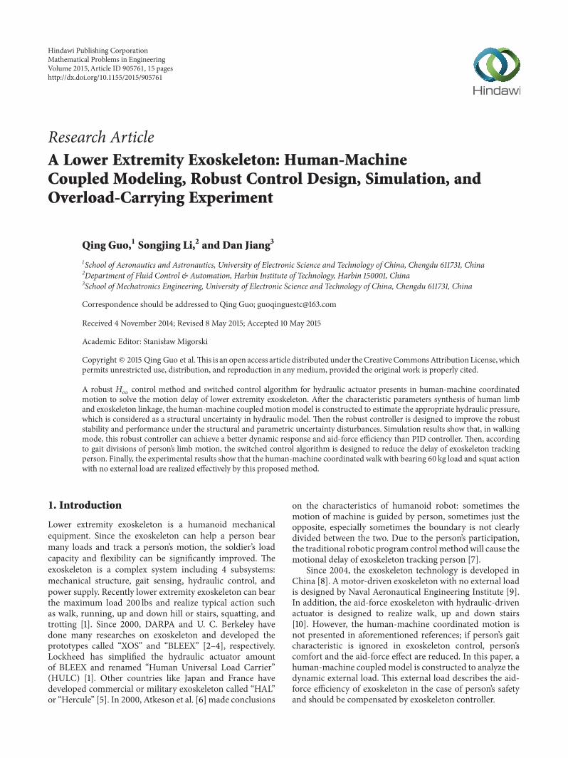
If the relative uncertainty Δ is from minus119868 to Δ = 119868 thesingular value of close-loop perturbed is 028 which is lessthan 1 shown in Figure 7 The close-loop system 119866
119888is stable
and its relative uncertainties Δ can be extended to 1028In Figure 8 the maximum singular value 120583 of close-loop
shows that the robust performance requirement is 14 which
8 Mathematical Problems in Engineering
Frequency (rads)
Upper boundLow bound
100
10minus1
10minus3
10minus2
100 101 10210minus110minus210minus4
120583
Figure 7 The maximum robust stability bound with varyinguncertainty parameters119870
119902 119864 119887 and 119870
119865119901
NominalUpper bound
Low bound
Frequency (rads)
100
10minus02
10minus06
10minus04
100 101 10210minus110minus2
120583
Figure 8 The maximum robust performance bound with varyinguncertainty parameters119870
119902 119864 119887 and 119870
119865119901
means that the steady tracking accuracymay not be excellentBut in middle and high frequency stage from 4 to 100 radsthe dynamic tracking performance and robustness marginmeet the requirement [32]
After iterative design the robust controller is 7 ordersTaking the actual project into account the controller shouldbe reduced into lower order by Balanced Truncation Method[33] So the controller is simplified to 4 orders as follows
119906extension = 119870 (119904) (119910 minus 119910)
=1198994119904
4+ 1198993119904
3+ 1198992119904
2+ 1198991119904 + 1198990
11988941199044 + 1198893119904
3 + 11988921199042 + 1198891119904 + 1198890
(119910 minus 119910)
(27)
where 119899119894(119894 = 0 4) 119889
119894(119894 = 0 4) are numerator and
denominator constant 119910 is demand input and 119910 is output
4 Gait Divisions of Coordinated Motion
In this section the gait phase divisions of 2 typical actionmodes are analyzed and designed According to the gaitidentification the switched control is realized to reduce
Single leg squat Up-squat
Walking cycle
The end for walk switch to a standing action
The end for squat switch to a standing action
Upper limb trunkLeft leg (thigh and shank)
Right leg (thigh and shank)
(1) (2) (3) (4) (5) (2)
(1) (6) (7) (8) (9) (2)
Figure 9 The gait subphases division of walk and squat action inhuman-machine coordinated motion
the delay of exoskeleton tracking person and improve thehuman-machine coupling effect
41 Walk Mode The walking gait law of human-machinecoordinate motion can be divided into 5 subphases shown inFigure 9 These subphases are (1) double standing (2) rightleg swing left leg stance (3) double stance with right leg frontand left leg back (4) right leg stance and left leg swing and(5) double stance with left leg front and right leg back
In order to improve the exoskeleton tracking personrsquosmotion 2 subphases (3) and (4) are merged That means ifthe subphases (3) are identified make the hydraulic cylinderof left leg retract in advance This operation realizes theexoskeleton ahead of person which helps person regulatethe center of system gravity easily in overload carryingcondition After the subphase (4) is identified by exoskeletonthe center of system gravity is steadily regulated by personSimultaneously the exoskeleton continuously realizes theright stance leg and the left swing leg The subphases (5)and (2) are similar to subphases (3) and (4) So the switchedcontrol algorithm is described in Table 1
In Table 1 119906119897and 119906
119903are control current of the of left and
right servo valve 119906max = plusmn40mA which is the maximumcurrent of servo
42 Squat Mode The squat gait law is divided into 6 sub-phases (1) double standing (6) left leg stance and right leguplift for preparation (7) left leg retraction gradually andright leg swing (8) left leg reached the minimum positionof cylinder and right knee contacting the ground whichmeans the single leg squat action ends (9) left leg extensiongradually and right leg swing and (2) left leg stance and rightleg swing which means the up-squat action ends and switchto the walking mode So the switched control algorithm isdescribed in Table 2
In gait (7) the left knee angle is retracted by fader controlThe symbol 119896 = 2 and 119905 is fader time
Mathematical Problems in Engineering 9
Table 1 The duty of exoskeleton and person in walking gaitsubphases by different switched controller form
Gait Controller Exoskeleton Person
(1) 119906119897= 119906extension
119906119903= 119906extension
Control doubleknee angle
Adapt toexoskeleton
(2) 119906119897= 119906extension119906119903= minus119906max
Control leftknee angle andretract right leg
Adapt toexoskeleton
(3) 119906119897= minus119906max
119906119903= 119906extension
Adapt to personand retract leftleg in advance
Regulate thecenter of gravity
(4) 119906119897= minus119906max
119906119903= 119906extension
Control rightknee angle andretract left leg
Adapt toexoskeleton
(5) 119906119897= 119906extension119906119903= minus119906max
Adapt to personand retract rightleg in advance
Regulate thecenter of gravity
Table 2The duty of exoskeleton and person in squat gait subphasesby different switched controller form
Gait Controller Exoskeleton Person
(6) 119906119897= 119906extension119906119903= minus119906max
Control leftknee angle andretract right leg
Squatpreparation
(7)119906119897=
119906max(1 minus 119890minus119896119905
)
119906119903= minus119906max
Retract left kneeangle gradually
Adapt toexoskeleton
(8) 119906119897= minus119906max
119906119903= minus119906max
Adapt to personand hold in the
prescriptposture
Regulate thecenter of gravity
(9) 119906119897= 119906extension
119906119903= 119906extension
Control 2 kneeangles andextend 2 legs
Adapt toexoskeleton
To ensure the safety of person the squat preparation timeneed to be set as 2 or 3 sec The subphase (8) is identified bya pressure force sensor on the right kneeThe transition fromsubphase (8) to subphase (9) needs amode switch button andgait identification algorithm which is not described in thissection
5 Simulation Results
Thehydraulicmodel is simulatedwith the external load 60 kgThehydraulic parameters for simulation are shown inTable 3In order to verify the effectiveness of the proposed methodthe natural walking gait law is considered as the commandinput with 05Hz frequency The fore-half duration is stancephase for one leg with the range of knee angle from 15∘ to 30∘The afterwards duration is swing phase with range of kneeangle from 15∘ to 73∘
According to the above analysis of the load pressure119875119897 the
hydraulic supply pressure 119875119904is 8MPa and the external load
is 60 kg in simulation Some hydraulic parameters are shownin Table 3 The maximum relative uncertainties 119901
119870119902= 025
Table 3 The hydraulic parameters for simulation
Name Value UnitDamping ratio 120585sv 07 mdashNatural frequency 120596
119899628 rads
Servo valve gain 119870sv 00125 mAFluid bulk modulus 120573
1198907000 bar
Mass of hydraulic actuator119898 25 kgAnnulus areas of no-rod cylinder 119860
119886177 times 10
minus4 m2
Annulus areas of rod cylinder 119860119887
113 times 10minus4 m2
Distance between hydraulic cylindercalf connections and knee 119897
1
0322 m
Distance between hydraulic cylinderthigh connections and knee 1198972
0065 m
Return pressures 119901119903
1 barPiston stroke 119871
119903016 m
Flow-pressure coefficient 1198701
119888asymp 119870
2119888
518119890 minus 12 m3sPaNominal value of119870
1199020188 m2s
Nominal value of 119887 100 NsmNominal value of 119864 198119890 minus 14 m3paNominal value of119870
1198651199011200 Nm
0 1 2 3 4 5 6 7 8 9 10minus20
0
20
40
60
80
t (s)
4 45 515202530
Knee commandRobust control
PID control
Stan
ceph
ase
Swin
gph
ase
120579lk
(∘)
Figure 10 The left knee angle response of walking gait
119901119864= 07 119901
119887= 1 and 119901
119870119865119901= 300 Here 2 control methods are
used to make the exoskeleton track the person in the walkingmode simulationThePID control parameters are designed asthe best group which satisfy the frequency domain marginThe robust119867
infincontrol method is realized by (27)
The left knee angle response of exoskeleton is shownin Figure 10 In swing phase the dynamic characteristicof PID control is same as the robust 119867
infincontrol because
there is no external load on the hydraulic actuator But instance phase the dynamic performance of robust control isbetter than PID control due to the variable compensationforce 119865
119901provided by hydraulic actuator on the exoskeleton
This external force disturbance results in the parametricuncertainty of119870
119902 119864 which reduce the stabile margin of PID
control Importantly the control current needs to balance thecompensation force 119865
119901and stick-slip friction 119865
119891in the case
10 Mathematical Problems in Engineering
0 1 2 3 4 5 6 7 8 9 10t (s)
Position commandRobust control
PID control
4 45 5034
0345035
0355
03
032
034
036
038
yl
(m)
Figure 11Theposition response of left hydraulic cylinder ofwalkinggait
0 1 2 3 4 5 6 7 8 9 10minus20
minus10
0
10
20
30
40
t (s)
PID controlRobust control
ul
(m)
Figure 12 The left servo valve control current of walking gait
of positional error suppression In addition the asymmetriccylinder affects the dynamic characteristic of hydraulicmodelwhen cylinder extension switches into retraction especiallyin stance phase The parametric uncertainty of 119870
119902 119864 and 119887
and structural uncertainty 119865119901are considered in the system
model construction so the robust controller can guaranteethe dynamic performance in the whole duration of walkingmode
The dynamic cylinder position of left hydraulic actuatoron exoskeleton is shown in Figure 11 It is computed by (17)after the knee angle is measured by encoder The availabledisplacement of cylinder is 007m in waking mode whichis less than the maximal stroke 016m of cylinder It meansthat only half stroke is useful in human-machine coordinatedwalk But the maximal stroke of cylinder needs to satisfy thesquat mode which requires enough length of cylinder
The control current of left servo valve is shown inFigure 12 The general trend of control current is same using2 control methods But the robust controller 119906extension ismore intense than PID control especially in stance phaseBecause the controller involves the high order item therobust controller can reduce the tracking error quickly in the
0 1 2 3 4 5 6 7 8 9 10
minus1000
0
500
1000
15001300
minus500minus600
t (s)
Com
pens
atio
n fo
rce (
N)
Robust controlPID controlFpres response
Figure 13 The aid-force effect of exoskeleton by left hydraulicactuator
case of model uncertaintyThemaximal amplitude of controlcurrent is 30mA which does not exceed the maximal servovalve control current plusmn119906max
The aid-force effect of exoskeleton by left hydraulic actu-ator is shown in Figure 13 Here the demand compensationforce 119865pres is constructed by
119865pres =
119865119901
(119879120572119904 + 1)2
stance phase
(1 minus 1(119879120572119904 + 1)2
)119865119901
swing phase(28)
where 119879120572= 005 s is defined as the transition response time
of external load 119865119897
In Figure 13 the compensation force error means theerror between 119865pres and the hydraulic output actual force119865act In stance phase of left leg the compensation force errordoes not exceed 500N by the robust controller The demandcompensation force 119865pres is 1300N approximately It meansthat the load bearing efficiency is great than 60 in stancephase of left leg Because 2 legs are alternative in walking gaitthe left hydraulic actuator needs not to compensate 119865pres inits swing phase while the hydraulic actuator on right leg ofexoskeleton is in charge of this load bearing task Thereforethe aid-force effect of simulation result can not include thehydraulic output actual force in swing phase in this figure
6 Experimental Results
The human-machine coordinated motion is realized by atester wearing the exoskeleton prototype The gait can beidentified by 4 force sensors in the sensor shoes The 2knee angles of exoskeleton are measured by 2 encoders Thehydraulic control system includes a motor a fixed pump2 servo valves 2 cylinders and an embedded controlleron the mechanical brace The net weight of prototype is30 kg In walking mode the tester can bear no more than60 kg external load In squat mode the tester can realizethe basic gait with no external load due to the safety of
Mathematical Problems in Engineering 11
0 2 4 6 8 10 12 14 16minus20
0
20
40
60
80
t (s)
Left kneeRight knee
c ef
ga b d
120579k
(∘)
Figure 14 The knee angles of 2 legs in walking mode
tester The hydraulic actuators are controlled by the robustcontrol method and the control algorithm will be switchedin different gait
61 Walking Mode with Overloading In walking mode theextension and retraction of 2 legs are alternatively realized byhydraulic actuator The walking frequency is 05Hz bearingwith 60 kg load
The dynamic characteristics of 2 knee angles are shownin Figure 14 which includes 5 subphases of walking gait Ingait (4) described by time slice 119886sim119887 (08 ssim15 s) the left legis retracted by the tester himself and the control current ofleft leg is minus119906max shown in Figure 20 In gait (5) described bytime slice 119887sim119888 (15 ssim17 s) the left leg is extended by feedbackcontrol and the right leg begins to retract in advance to helpthe tester regulate the center of gravity This ahead of controlcan make the tester move easily In gait (2) described by timeslice 119888sim119889 (17 ssim24 s) the right leg is retracted by the testerhimself like as gait (4) In gait (3) described by time slice 119889sim119890(24 ssim26 s) the right leg is extended by feedback control likegait (5)These 4 subphases are switched frequently in walkingmode If the walking mode ends the double stance phase gait(1) will arise described by time slice 119891sim119892 (14 ssim156 s) In gait(1) 2 legs are controlled by feedback controlThe external loadis compensated by 2 hydraulic actuators on the exoskeletononly in stance phase In swing phase the exoskeleton shouldhelp the tester switch the center of gravity from one leg to theother leg Otherwise the human-machine coupled effect isreduced significantly and the tester may be at loss of balance
The cylinder positions of 2 hydraulic actuators in onecycle of walking mode are shown in Figure 15 Here theextended position commands are designed as a rising stepThe servo feedback control phase of left leg is described astime slice 119887sim119890 (15 ssim26 s) But in time slice 1198871sim1198872 (155 ssim165 s) the cylinder position is still retracted after the positivecontrol current output This response delay is caused by thebandwidth limitation of the whole hydraulic control systemThe pressure of cylinder is constructed with time-consuming08 s from 0 to stable value 8MPa So the available positionresponse of left cylinder is time slice 1198872sim 119890 (165 ssim26 s)
08 1 12 14 18 2 22 24 26165 2815
032
033
034
035
036
037
038
t (s)
Cylid
ner p
ositi
on (m
)
Left commandRight command
Left actualRight actual
a b2bb1
c d1
d2
d e
Figure 15 The cylinder positions of 2 hydraulic actuators in onecycle of walking mode
0 2 4 6 8 10 12 14 16minus40minus30minus20minus10
010203040
t (s)
Con
trol c
urre
nt (m
A)
Left controlRight control
a
c e f
gb1 d1
Figure 16 The control current of 2 servo valves in walking mode
where the actual position of cylinder tracks the extendedposition commands In time slice 119886sim119887 the retracted positioncommands of left leg is designed as a fall step It is not a servocontrol phase for left leg So the control current of servo valveis minus maximal value minus119906max directly in order to help thetester retract the cylinder quicklyThe dynamic characteristicof right cylinder positions is similar to the left cylinder
The switched control currents correspond to 5 subphasesshown in Figure 16 The servo control phase of left leg istime slice 1198871sim 119890 (155 ssim26 s) in one cycle Similarly theservo control phase of right leg is starting at time 1198891 Indouble stance phase described by time slice 119891sim119892 the servocontrol value is near 0 after 2 knee angles reach the testerrsquosstance posture The dynamic pressures of 2 hydraulic actu-ators are shown in Figure 17 In stance phase the pressureis constructed from 0 to 8MPa with approximately 08 stime consumed due to bearing heavy load In swing phasethe fast time-consuming is 04 s for pressure from 8MPa to0 It reveals that personrsquos active control can be faster thanthe control response of exoskeleton if the walking speed ispossible So the switched control algorithm shown in Table 1is suitable for human-machine coordinated walk
12 Mathematical Problems in Engineering
0 2 4 6 8 10 12 14 160
2
4
6
8
10
t (s)
Pres
sure
(MPa
)
PlPr
Figure 17 The pressures of 2 hydraulic actuators in walking mode
62 SquatMode Test According to Figure 9 6 gait subphasesof squat mode are realized by switched control algorithmshown in Table 2 The dynamic characteristics of 2 kneeangles in squat mode are shown in Figure 18 The gaitsubphases are described by time slice ℎsim119894 (0 ssim2 s) 119894sim119895 (2 ssim4 s) 119895sim119896 (4 ssim7 s) 119896sim119897 (7 ssim29 s) 119897sim119898 (29 ssim32 s) and 119898sim119899 (32 ssim35 s) respectively In gait (5) described as time sliceℎsim 119894 the double stance phase should be passed before thesquat mode begins The cylinder positions are controlled toreach the testerrsquos stance posture shown in Figure 19 In gait(6) described as time slice 119894sim119895 the right leg swings to pre-pare the squat action and the tester regulates the center ofgravity at this moment In gait (7) described as time slice119895sim119896 the left cylinder is retracted gradually by exponentialfader control shown in Table 2 So the left leg bends graduallybefore the right knee contacts the groundThe control currentis reduced from 0 to minus119906max in 3 sec shown in Figure 20 Ingait (8) described as time slice 119896 sim 119897 2 control currents areminus maximal value The exoskeleton can not compensateits mass by 2 hydraulic actuators at this phase The tester canbear the load himself through regulating the center of gravityto reduce the backward torque caused by exoskeleton massandhold in the prescript posture In gait (9) described as timeslice 119897 sim 119898 2 cylinders are extended to realize the up-squataction in 3 sec (Figure 21)The cylinder positions of 2 legs arecontrolled by robust control algorithm to reach the suitablepositions where gait (9) is switched into gait (2) After up-squat phase ends the squat mode will return to the walkingmode
63 Experimental Scene The experimental scenes of human-machine coordinated motion are shown in Figures 22 and23 In walking mode the tester can bear the external load60 kg hung on the back frame of exoskeleton When thewaking gait is switched the tester will bear a little moreload himself due to the regulation of center of gravity In thestable stance phases such as double standing or single legstance the exoskeleton can guarantee the aid-force effect bythe proposed robust controller Also the comfortable effect oftester is improved by the switched control algorithm
0 5 10 15 20 25 30 35 40
0
50
100
150
80
t (s)
Left kneeRight knee
h i j
lk
mn
minus50
120579k
(∘)
Figure 18 The knee angles of 2 legs in squat mode
0 10 20 30 40025
03
035
04
045Cy
lidne
r pos
ition
(m)
Left actualRight actual
t (s)
Figure 19 The cylinder position of 2 hydraulic actuators in squatmode
010203040
Con
trol c
urre
nt (m
A)
Left controlRight control
h i j
k
m n
l
0 5 10 15 20 25 30 35 40t (s)
minus10
minus20
minus30
minus40
Figure 20 The control current of 2 servo valves in squat mode
Mathematical Problems in Engineering 13
0 10 20 30 400
2
4
6
8
10
t (s)
Pres
sure
(MPa
)
ihj
k l
m n
PlPr
Figure 21 The pressures of 2 hydraulic actuators in squat mode
(a) Gait (1) (b) Gait (2) (c) Gait (3)
(d) Gait (4) (e) Gait (5)
Figure 22 The walking gait subphases experiment
14 Mathematical Problems in Engineering
(a) Gait (6) (b) Gait (7)
(c) Gait (8) (d) Gait (9)
Figure 23 The squat gait subphases experiment
In squat mode the tester only bears the exoskeleton massbecause of the safety of system at the present stage The testercan realize the basic gait of squat action under the help ofanother personrsquos arm especially in gait (7) and gait (9)
7 Conclusion
In this paper a human-machined coordinatedmotion controlmethod is presented to realize the aid-force of lower extremityexoskeleton This proposed method improves the robustperformance under the structural andparametric uncertaintydisturbance The positions of 2 hydraulic actuators are con-trolled to make exoskeleton track personrsquos motion by outputfeedback control Compared with conventional PID controlmethod in simulation the proposed method can achieve abetter dynamic response performance and aid-force effect instance phase of walking gait According to the gait divisions ofhuman-machined coordinated motion the switched controlalgorithm is designed to reduce the delay of exoskeletontracking personThe experimental results of 2 motion modesvalidate the effectiveness of this proposed method and gaitswitched control algorithm
Conflict of Interests
The authors declare that there is no conflict of interestsregarding the publication of this paper
Acknowledgments
This research was supported by project of National Nat-ural Science Foundation of China (no 61305092 and no51205045) and project of China Postdoctoral Science Foun-dation (no 2013M542487) The authors would like to thankanonymous reviewers for their valuable comments and sug-gestions
References
[1] S Ackerman The Report of Production Display for ldquoHULCrdquoMade in Lockheed Martin Montgomery County Md USA2010 httpwwwlockheedmartincom
[2] Z X Wang ldquoRaytheon launched XOS2 second-generationexoskeleton devicerdquo Light Weapons pp 24ndash44 2010
Mathematical Problems in Engineering 15
[3] J R Steger A design and control methodology for humanexoskeletons [PhD dissertation] Department of MechanicalEngineering University of California Berkeley Calif USA2006
[4] J F Veneman R Ekkelenkamp R Kruidhof F C T vander Helm and H van der Kooij ldquoDesign of a series elastic-and Bowden cable-based actuation system for use as torque-actuator in exoskeleton-type trainingrdquo in Proceedings of theIEEE 9th International Conference on Rehabilitation Robotics(ICORR rsquo05) pp 496ndash499 Chicago Ill USA July 2005
[5] Verge ldquoThe report of lsquoHercule exoskeleton can help a regularhuman carry up to 220 poundsrsquordquo 2012 httpwwwthevergecom20122222815704hercule-exoskeleton-human-carry-220-pounds
[6] C G Atkeson J G Hale F Pollick et al ldquoUsing humanoidrobots to study human behaviorrdquo IEEE Intelligent Systems andTheir Applications vol 15 no 4 pp 46ndash55 2000
[7] Q Guo H Zhou and D Jiang ldquoCoordinated control methodof the lower extremity exoskeleton based on human elec-tromechanical couplingrdquo in Social Robotics 4th InternationalConference ICSR 2012 Chengdu China October 29ndash31 2012Proceedings vol 7621 of Lecture Notes in Computer Science pp650ndash659 Springer Berlin Germany 2012
[8] Q Li M Kong Z Du L Sun and D Wang ldquoInteractiverehabilitation exercise control strategy for 5-DOF upper limbrehabilitation armrdquo Chinese Journal of Mechanical Engineeringvol 44 no 9 pp 169ndash176 2008
[9] Z Y Yang Y S ZhangW J Gu et al ldquoBone clothing sensitivityamplification controlrdquo Computer Simulation vol 27 no 1 pp177ndash180 2010
[10] H Cao X W Meng Z Y Ling et al ldquoTwo-legged robotexoskeleton plantar pressure measurement systemrdquo Journ ofSensors and Actuators vol 23 no 3 pp 326ndash330 2010
[11] R Fales and A Kelkar ldquoRobust control design for a wheelloader using 119867
infinand feedback linearization based methodsrdquo
ISA Transactions vol 48 no 3 pp 312ndash320 2009[12] G P Liu and S Daley ldquoOptimal-tuning PID controller design
in the frequency domain with application to a rotary hydraulicsystemrdquo Control Engineering Practice vol 7 no 7 pp 821ndash8301999
[13] I Boiko ldquoVariable-structure PID controller for level processrdquoControl Engineering Practice vol 21 no 5 pp 700ndash707 2013
[14] M Moradi ldquoSelf-tuning PID controller to three-axis stabi-lization of a satellite with unknown parametersrdquo InternationalJournal of Non-Linear Mechanics vol 49 pp 50ndash56 2013
[15] O Cerman and P Husek ldquoAdaptive fuzzy sliding mode controlfor electro-hydraulic servo mechanismrdquo Expert Systems withApplications vol 39 no 11 pp 10269ndash10277 2012
[16] C Guan and S X Pan ldquoAdaptive sliding mode control ofelectro-hydraulic systemwith nonlinear unknown parametersrdquoControl Engineering Practice vol 16 no 11 pp 1275ndash1284 2008
[17] D H Sha V B Bajic and H Y Yang ldquoNew model and slidingmode control of hydraulic elevator velocity tracking systemrdquoSimulation Practice and Theory vol 9 no 6ndash8 pp 365ndash3852002
[18] C W Wang Z X Jiao S Wu and Y X Shang ldquoNonlinearadaptive torque control of electro-hydraulic load system withexternal active motion disturbancerdquo Mechatronics vol 24 no1 pp 32ndash40 2014
[19] I Ursu A Toader A Halanay and S Balea ldquoNew stabilizationand tracking control laws for electrohydraulic servomecha-nismsrdquo European Journal of Control vol 19 no 1 pp 65ndash802013
[20] V Milic Z Situm and M Essert ldquoRobust 119867infin
positioncontrol synthesis of an electro-hydraulic servo systemrdquo ISATransactions vol 49 no 4 pp 535ndash542 2010
[21] F L Weng Y C Ding and M K Tang ldquoLPV model-basedrobust controller design of electro-hydraulic servo systemsrdquoProcedia Engineering vol 15 pp 421ndash425 2011
[22] X Song Y Wang and Z Sun ldquoRobust stabilizer design forlinear time-varying internal model based output regulation andits application to an electrohydraulic systemrdquo Automatica vol50 no 4 pp 1128ndash1134 2014
[23] R Fales andAKelkar ldquoRobust control design for awheel loaderusing mixed sensitivity H-infinity and feedback linearizationbased methodsrdquo in Proceedings of the American Control Confer-ence (ACC rsquo05) pp 4381ndash4386 Portland Ore USA June 2005
[24] S Kawamura and M Svinin Advances in Robot Control FromEveryday Physics to Human-like Movements Springer BerlinGermany 2006
[25] A Akers M Gassman and R Smith Hydraulic Power SystemAnalysis Taylor amp Francis Group 2006
[26] A Alleyne and R Liu ldquoA simplified approach to force controlfor electro-hydraulic systemsrdquoControl Engineering Practice vol8 no 12 pp 1347ndash1356 2000
[27] W-M Lu K M Zhou and J C Doyle ldquoStabilization ofuncertain linear systems an LFT approachrdquo IEEE Transactionson Automatic Control vol 41 no 1 pp 50ndash65 1996
[28] M K H Fan A L Tits and J C Doyle ldquoRobustness inthe presence of mixed parametric uncertainty and unmodeleddynamicsrdquo IEEE Transactions on Automatic Control vol 36 no1 pp 25ndash38 1991
[29] D W Gu P H Petkov and M M Konstantinov Robust controldesign with MATLAB Springer Press 2005
[30] J C Doyle K Glover P P Khargonekar and B A FrancisldquoState-space solutions to standard 119867
2and 119867
infincontrol prob-
lemsrdquo IEEE Transactions on Automatic Control vol 34 no 8pp 831ndash847 1989
[31] G J Balas and J C Doyle ldquoRobustness and performance trade-offs in control design for flexible structuresrdquo IEEE Transactionson Control Systems Technology vol 2 no 4 pp 352ndash361 1994
[32] A Packard M K H Fan and J C Doyle ldquoA power method forthe structured singular valuerdquo in Proceedings of the 27th IEEEConference on Decision and Control pp 2132ndash2137 Chicago IllUSA December 1988
[33] W Gawronski ldquoBalanced systems and structures reductionassignment and perturbationsrdquo in Control and Dynamic Sys-tems vol 54 pp 373ndash415 1992
Submit your manuscripts athttpwwwhindawicom
Hindawi Publishing Corporationhttpwwwhindawicom Volume 2014
MathematicsJournal of
Hindawi Publishing Corporationhttpwwwhindawicom Volume 2014
Mathematical Problems in Engineering
Hindawi Publishing Corporationhttpwwwhindawicom
Differential EquationsInternational Journal of
Volume 2014
Applied MathematicsJournal of
Hindawi Publishing Corporationhttpwwwhindawicom Volume 2014
Probability and StatisticsHindawi Publishing Corporationhttpwwwhindawicom Volume 2014
Journal of
Hindawi Publishing Corporationhttpwwwhindawicom Volume 2014
Mathematical PhysicsAdvances in
Complex AnalysisJournal of
Hindawi Publishing Corporationhttpwwwhindawicom Volume 2014
OptimizationJournal of
Hindawi Publishing Corporationhttpwwwhindawicom Volume 2014
CombinatoricsHindawi Publishing Corporationhttpwwwhindawicom Volume 2014
International Journal of
Hindawi Publishing Corporationhttpwwwhindawicom Volume 2014
Operations ResearchAdvances in
Journal of
Hindawi Publishing Corporationhttpwwwhindawicom Volume 2014
Function Spaces
Abstract and Applied AnalysisHindawi Publishing Corporationhttpwwwhindawicom Volume 2014
International Journal of Mathematics and Mathematical Sciences
Hindawi Publishing Corporationhttpwwwhindawicom Volume 2014
The Scientific World JournalHindawi Publishing Corporation httpwwwhindawicom Volume 2014
Hindawi Publishing Corporationhttpwwwhindawicom Volume 2014
Algebra
Discrete Dynamics in Nature and Society
Hindawi Publishing Corporationhttpwwwhindawicom Volume 2014
Hindawi Publishing Corporationhttpwwwhindawicom Volume 2014
Decision SciencesAdvances in
Discrete MathematicsJournal of
Hindawi Publishing Corporationhttpwwwhindawicom
Volume 2014 Hindawi Publishing Corporationhttpwwwhindawicom Volume 2014
Stochastic AnalysisInternational Journal of

2 Mathematical Problems in Engineering
Due to the demands of high load efficiency and fastresponse lower extremity exoskeleton is driven by theelectrohydraulic servo system (EHSS) However EHSS hassome model uncertainties such as parametric disturbancesstructural uncertainties which are consequences of hydraulicphysical characteristics oil leakage oil temperature varia-tions and characteristics of valves near null [11]The classicalcontrol method of EHSS is PID [12] Due to lower orderand constant gains PID control is easy to be realized inengineering So the variable parameters of PID controllerare presented to suit the hydraulic dynamic characteristic[13 14] Some advanced control methods such as adaptivesliding mode [15ndash17] and backstepping controllers [18 19] areused in EHSS and get some good performance In additionthe robust controllers [20ndash22] of EHSS are presented withparameter uncertainty disturbance which are converted to119867infin
control problem solved by conventional robust analysisor linear matrix inequality The mixed sensitivity119867
infincontrol
method [23] of EHSS is presented to balance to the robuststability and response performance But the external load ofhydraulic control model is only considered as a disturbancenot to be quantitatively analyzed and described in robustuncertainty model In this paper by referring to119867
infincontrol
method aforementioned references a robust119867infincontroller is
designed to suppress structural uncertainty and parametricuncertainties which are caused by the external load andparametric disturbances Furthermore combined with theswitched control algorithm of hydraulic actuator this 119867
infin
controller can reduce the delay of exoskeleton trackingperson Simulation and experimental results validate thisproposed controller
2 Human-Machine CoupledModel Construction
Since human fast conscious is ahead of exoskeleton the onlymechanical motion model is not insufficient to analyze thesystematic dynamics So the coupled motion model needs tobe constructed to estimate the dynamic loads and the supplypower
21 Characteristic Parameters Synthesis Some characteristicparameters like mass and moment of inertia are differentbetween human limb and exoskeleton linkage So the char-acteristic parameters need be synthetic to balance 2 motionresponses activated by person and exoskeleton It meansthat human-constraint is relieved but not vanished throughequivalent multibody motion The human-constraint is asmall value in the thigh bandage which can not exceed thehuman tolerance
If the sagittal motion is considered only the rotationalmotion around the knee is shown in Figure 1 Here compo-nents 119861
1 119861
2 119861
3 119861
4 and 119861
5represent respectively human
calf mechanical calf sensing shoes human thigh andmechanical thigh
O
ltl5cltc
l4c
l3c
l3c
l1c l2c
B5B4
m1g
m2g
m3g
m4g
msg
m5g
mtg
C
B1
B2
B3
KA
Figure 1The rotationalmotion around the knee of human-machinesynthetic model
The centers of synthetic calf and thigh for human-machine coordinated motion [24] are shown as
119897119904119888=11989811198971119888 + 11989821198972119888 + 119898311989731198881198981 + 1198982 + 1198983
=11989811198971119888 + 11989821198972119888 + 11989831198973119888
119898119904
(1a)
119897119905119888=11989841198974119888 + 119898511989751198881198984 + 1198985
=11989841198974119888 + 11989851198975119888
119898119905
(1b)
According to the moment of inertia of the parallel axistheorem the moment of inertia of synthetic calf and thigharound respective center of mass is shown as
119868119904119888= [1198681119888 +1198981 (119897119904119888 minus 1198971119888)
2] + [1198682119888 +1198982 (119897119904119888 minus 1198972119888)
2]
+ [1198683119888 +1198983 (119897119904119888 minus 1198973119888)2]
(2a)
119868119905119888= [1198684119888 +1198984 (119897119905119888 minus 1198974119888)
2] + [1198685119888 +1198985 (119897119905119888 minus 1198975119888)
2] (2b)
where 119898119894is the 119894th component mass 119898
119904and 119898
119905are the total
masses of equivalent calf and thigh 1198971119888 1198972119888 and 119897
3119888are the
distances from center of mass to knee respectively 1198974119888 1198975119888are
the distances from center of mass to hip respectively and 119868119894119888
is the 119894th moment of inertia around respective center of mass
22 Human-Machine Coupled Motion Model In human-machine coordinated motion the exoskeleton linkagesshould compensate the load when human foot contacts theground So in the stance phase of walk or squat the hydraulicactuator not only realizes the exoskeleton knee rotationtracking human limb rotation but also balances the variableload In order to estimate the dynamic load on the hydraulic
Mathematical Problems in Engineering 3
Fl
O5
O4
5
4
3
2
1
1205791
1205793
120579k
Fp
O2
O3
O1
A
X
Y
FO2y
FO2x
1FO3x
FO3y
aGsy
aGsxGs
a120591s
ans120572O1
120596O1
FO1x
FO1y
TO1
TO1
1205791
1205792
FO4x
FO2x
FO2y
Fl
FO4y
a120591t
aGtx
aGty
ant
Gt
2
120572O2
120596O2
FO4x
FO3x
FO3y
FA
TA
Fp
FA
Fp
FO4y
a120591p
a120591c
anc
anp 4
120572c120596c
3TA
1205792
120572p 120596p
(a) (b)
(c) (d)
Figure 2 The synthetic model of human-machine coupled motion (linkages 1 and 2 represented the synthetic calf and thigh)
actuator the human-machine coupled motion model needsto be constructed in Figure 2 The link point ldquo119874
5rdquo between
mechanical back frame and thigh is the hip joint The anklejoint ldquo119874
1rdquo is equivalent to a hinge when human foot contacts
the ground The external load ldquo119865119897rdquo including the exoskeleton
mass and effective load hung at the back frameThe force ldquo119865119901rdquo
provided by hydraulic actuator compensates the load on theexoskeleton
The force andmoment equilibriumequations of 1 linkage(synthetic calf) are shown as
1198651198741119909 minus1198651198742119909 +1198651198743119909 = 119898119904119888
119886119866119904119909 (3a)
1198651198741119910 +1198651198742119910 minus1198651198743119910 minus119898119904119888
119892 = 119898119904119886119866119904119910 (3b)
1198791198741 +1198651198742119909119897119904119888 cos 1205791 +1198651198742119910119897119904119888 sin 1205791
minus1198651198743119909 (119897119904119888 minus 1198971) cos 1205791 minus1198651198743119910 (119897119904119888 minus 1198971) sin 1205791
minus119898119904119888119892119897119892119904sin 1205791 = minus 1198681199041198881205721198741
(3c)
119886119866119904119909
= 1198861198741119909 minus 119886119899119904 sdot cos 1205791 + 119886120591119904 sdot sin 1205791
119886119866119904119910
= 1198861198741119910 minus 119886119899119904 sdot sin 1205791 minus 119886120591119904 sdot cos 1205791
(3d)
where 119886119899119904= 119897
119892119904sdot 120596
21198741 119886120591119904 = 119897119892119904 sdot 1205721198741 1198861198741119909 = 1198861198741119910 = 0
Similarly the 2 linkage (synthetic thigh) 3 linkage(piston) and 4 linkage (cylinder) can also be analyzed asfollows
1198651198742119909 +1198651198744119909 = 119898119905
119886119866119905119909 (4a)
1198651198744119910 minus1198651198742119910 minus119898119905119888
119892minus119865load = 119898119905119886119866119905119910 (4b)
minus119865119897119897119905119888cos (120579
119896+ 1205791) + 11986511987441199091198972cos (120579119896 + 1205791)
minus 11986511987441199101198972sin (120579119896 + 1205791) +119898119905
119892119897119892119905sin120579
119896= 119868
1199051198881205721198742
(4c)
119865119901sin1205792 minus119865119860cos1205792 +1198651198743119909 = 119898119901
119886119866119901119909 (5a)
4 Mathematical Problems in Engineering
minus119865119901cos1205792 minus119865119860sin1205792 +1198651198743119910 = 119898119901
119886119866119901119910 (5b)
minus119865119860119897119903+119879
119860= 119868
119901120572119901 (5c)
minus119865119901sin1205792 +119865119860cos1205792 minus1198651198744119909 = 119898119888
119886119866119888119909 (6a)
119865119901cos1205792 +119865119860sin1205792 minus1198651198744119910 = 119898119888
119886119866119888119910 (6b)
minus119865119860(119897ℎminus 119897
119903) minus119879
119860= 119868
119888120572119888 (6c)
Some angle and angular velocity relations in Figure 2 areas follows
sin 1205791 =1198972 sin 120579119896
radic11989721 + 119897
22 minus 211989711198972 cos 120579119896
(7a)
sin 1205793 =(1198972 minus 119897119905119888) sin 120579119896
radic1198972119904119888+ (1198972 minus 119897119905119888)
2minus 2119897
119904119888(1198972 minus 119897119905119888) cos 120579119896
(7b)
1205792 = 1205793 minus 1205791 (7c)
120596119901= 120596
1198741
minus
1198972 cos 120579119896120596119896 + 1198972 sin 120579119896 (11989711198972 sin 120579119896120596119896radic11989721 + 11989722 minus 211989711198972 cos 120579119896)
cos 1205793 (11989721 + 11989722 minus 211989711198972 cos 120579119896)
(8a)
120596119888= 120596
1198742
minus
1198971 cos 120579119896120596119896 + 1198971 sin 120579119896 (11989711198972 sin 120579119896120596119896radic11989721 + 11989722 minus 211989711198972 cos 120579119896)
cos (120587 minus 120579119896minus 1205793) (119897
21 + 119897
22 minus 211989711198972 cos 120579119896)
(8b)
1205961198742 = 120596119896 +1205961198741 (8c)
In above equations some parameters are defined asfollows
Description of Some Motion and Geometry Parameter Con-sider the following
1198651198741119909
1198651198741119910
force from hinge 1198741to linkage 1
1198651198742119909
1198651198742119910
force from linkage 1 to linkage 21198651198743119909
1198651198743119910
force from linkage 1 to linkage 31198651198744119909
1198651198744119910
force from linkage 2 to linkage 4119886119866119904119909
119886119866119904119910
calf acceleration at the center of gravity119886119866119905119909
119886119866119905119910
thigh acceleration at the center of gravity119886120591119904 119886
119899119904 tangential and normal acceleration of calf
acceleration119886120591119905 119886119899119905 tangential and normal acceleration of thigh
119886120591119901 119886119899119901 tangential and normal acceleration of piston
119886120591119888 119886
119899119888 tangential and normal acceleration of cylin-
der119897119892119904 length between the center of gravity calf and the
ankle119897119892119905 length between the center of gravity thigh and the
knee1198971 1198972 distance between hydraulic cylinder calf thigh
connections and knee
1205961198741 120572
1198741 angular velocity and angular acceleration of
calf around the ankle1205961198742 120572
1198742 angular velocity and angular acceleration of
thigh around the knee120596119896 knee angular velocity
119868119901 moment of inertia of piston around the leg con-
nection point1198791198741 torque from point 119874
1
120596119901 120572
119901 angular velocity and angular acceleration of
piston120596119888 120572
119888 angular velocity and angular acceleration of
cylinder119865119901 radial force along the piston
119865119860 normal force perpendicular to cylinder
119879119860 torque from point 119874
3
1205791 angle between linkage 1 and vertical line
1205792 angle between piston and vertical line
1205793 angle between piston and linkage 1
120579119896 knee angle
119898119901119898
119888 piston and cylinder mass
119897ℎ total length of hydraulic actuator119897119903 length of piston
If knee angle 120579119896and angular velocity 120596
119896are given (1a)ndash
(8c) can get the analytical solution ldquo119865119901rdquo So load pressure ldquo119875
119897rdquo
of the hydraulic actuator can be computed by
119875119897=
119865119901
1205871199032119901
(9)
where ldquo119903119901rdquo is hydraulic cylinder diameter
Now the person can realize 2 typical actions walk andsquat after wearing the exoskeleton The motional rangeof knee angle is from 85∘ to 155∘ in the gait duration ofthese actions In addition the maximum external load onthe back frame of exoskeleton is 60 kg Substituting someknown parameters into (3a)ndash(9) the load pressure 119875
119897can
be computed digital simulation method shown in Figure 3So if the external Load ldquo119865
119897rdquo does not exceed 90 kg the
load pressure 119875119897will not be more than 8MPa It means
that the hydraulic supply pressure ldquo119875119904rdquo can be set as 8MPa
to appropriately compensate the external load 60 kg If theperson wears the exoskeleton with no effective load thesupply pressure is chosen as 4MPa to balance the exoskeletonmass
23 Hydraulic Model The electrohydraulic servo controlsystem is also fixed on the exoskeleton It has 2 differentcharacteristics the asymmetric hydraulic cylinder and thesingle-rod actuator The dynamics of servo valve can bedescribed as follows
119909v119906=
119870sv1205962sv
1199042 + 2120577sv120596sv119904 + 1205962sv (10)
Mathematical Problems in Engineering 5
80 90 100 110 120 130 140 150 160123456789
120579k (∘)
Fl = 0kgFl = 30kg
Fl = 60kgFl = 90kg
Pl
(MPa
)
Figure 3The load pressure 119875119897in the gait duration of walk and squat
varying load and knee angle
where 120577sv is the damping ratio 120596sv is natural frequency and119870sv is the servo valve gain
The flow equations can be linearized as follows [25]
119876119886= 119870
1119902119909v minus119870
1119888119901119886 (11a)
119876119887= 119870
2119902119909v +119870
2119888119901119887 (11b)
1198701119902= 119862
119889119908radic
2Δ119901119901
120588
1198702119902= 119862
119889119908radic
2Δ119901119877
120588
(12a)
1198701119888=
1003816100381610038161003816100381610038161003816100381610038161003816100381610038161003816
119862119889119908119909v
radic2120588Δ119901119901
1003816100381610038161003816100381610038161003816100381610038161003816100381610038161003816
1198702119888=
100381610038161003816100381610038161003816100381610038161003816
119862119889119908119909v
radic2120588Δ119901119877
100381610038161003816100381610038161003816100381610038161003816
(12b)
Δ119901119901=
1003816100381610038161003816119901119904 minus 1199011198861003816100381610038161003816 119909v ge 0
1003816100381610038161003816119901119886 minus 1199011199031003816100381610038161003816 119909v lt 0
(13a)
Δ119901119877=
1003816100381610038161003816119901119887 minus 1199011199031003816100381610038161003816 119909v ge 0
1003816100381610038161003816119901119904 minus 1199011198871003816100381610038161003816 119909v lt 0
(13b)
where 119876119886 119876
119887are 2 sides of cylinder flow 119901
119886 119901
119887are the
cylinder chamber pressures 119901119904 119901
119903are supply and return
pressures 119862119889is the valve coefficient of discharge 119908 is the
valve orifice area gradient 120588 is the oil density and 119909v is thespool valve position1198701
119902(119870
2119902) and1198701
119888(119870
2119888) are flow gains of the
servo valve and flow-pressure coefficient
If the internal and external leakages are neglected theflow-pressure continuous equation of cylinder is shown asfollows
119886=
120573119890
11988101 + 119860119886119910(119876
119886minus119860
119886119910) (14a)
119887=
120573119890
11988102 minus 119860119887119910(minus119876
119887+119860
119887119910) (14b)
11988101 = 11988102 =119881119905
2=119860119886119897ℎ
2 (15)
where120573119890is the fluid bulkmodulus119860
119886and119860
119887are the annulus
areas of 2 sides of the cylinder1198810111988102 are half-volume of thecylinder and 119910 is the cylinder position
The mechanical dynamic equation is shown as follows
119898 119910 = (119901119886119860119886minus119901
119887119860119887minus119865
119891minus119865
119901) (16)
where 119865119891is the stick-slip friction caused by the viscous damp
of oil and 119865119901is the variable load on the hydraulic actuator
If the knee angle is known the linear position of cylinder119910 can be correspondingly computed by geometric relation-ship as follows
119910 (120579119896) = radic119897
21 + 119897
22 minus 2 times 1198971 times 1198972 times cos 120579
119896 (17)
According to the analytical computation method of theload pressure 119875
119897by (9) the linear expression between 119865
119901and
119910 can be constructed as follows
119865119901(120579119896 119865119871) = 119870
119865119901(120579119896) 119910 (120579
119896) (18)
where119870119865119901represents a variable bounded scale with load and
knee angleThe stick-slip friction often includes 2 items a stick phase
119865119891static which occurs when velocity is within a small critical
velocity range and a slip friction 119865119891slip which is the same
as Coulomb friction model [26] Here the slip friction canbe estimated by simplified parameter identification methodHere the stick item is neglected so the stick-slip friction 119865
119891
can be approximately described as follows
119865119891asymp 119887 119910 (19)
where 119887 is the viscous damping coefficient of oilThe slip friction 119865
119891slip should be constructed in thesimulation model to identify the parameters 119887 The max-imum stroke of cylinder is controlled by one best PIDcontrol parameters to track the square demand The com-parison results are shown in Figure 4 The simulation resultof hydraulic position is similar to the experiment whenparameters 119887 are 100 especially the dynamic response isbetter than other conditions So the nominal value of 119887 canbe approximately identified to be used in the parametricuncertainty model in Section 3
3 Robust Controller Design
Lower extremity exoskeleton provides two features high loadbearing and fast motion So exoskeleton should have fast
6 Mathematical Problems in Engineering
0 2 4 6 8 10 12 14minus002
0
002
004
006
008
01
012
014
t (s)
y (m
)
Experimentb = 100
b = 200b = 300
Figure 4 The square response of experiment and simulationvarying the viscous damping coefficient 119887
responses but should not hinder the wearer In this sectiona robust controller is designed to improve the dynamicresponse The knee angle will be servo controlled to realizethe human-machine coordinated motion Because this EHSShas parametric disturbances and structural uncertaintiesthe robust 119867
infincontrol method is presented to satisfy the
requirement of close-loop stability and robust performanceAfter the uncertainty model of the EHSS is constructed therobust controller is designed to find the 119867
infinsuboptimal
controller
31 Uncertainty Model Construction This EHSS has someparametric uncertainties the flow gains of servo valve 119870119894
119902
(119894 = 1 2) the viscous damping coefficient 119887 the effectivebulk modulus 120573 and variable volume of 2 sides cylinder(11988101+119860
119886119910 119881
02minus119860
119887119910) and a structural uncertainty119870
119865119901from
external load These uncertainties parameters 119870119902 119864 119887 and
119870119865119901are described by upper Linear Fractional Transformation
[27 28] as follows
119872119870119902= [
[
0 119870119902
119901119870119902
119870119902
]
]
119872119864=
[[[
[
minus119901119864
1119864
minus119901119864
1119864
]]]
]
119872119887= [
0 119887
119901119887119887
]
119872119870119865119901
= [
0 1
119901119870119865119901
119870119865119901
]
(20)
119870119902= 119870
119902(1+119901
119870119902120575119870119902) minus1 le 120575
119870119902le 1 (21a)
119864 = 119864 (1+119901119864120575119864) minus1 le 120575
119864le 1 (21b)
119887 = 119887 (1+119901119887120575119887) minus1 le 120575
119887le 1 (21c)
119870119865119901= 119870
119865119901+119901
119870119865119901120575119870119865119901 (21d)
where119864 = 1198811199052120573119870
119902119864 and 119887 are the nominal values 120575
119870119902 120575119864
and 120575119887are relative variation respectively and the maximum
relative uncertainties119901119870119902119901
119864 and119901
119887can be estimated varying
some hydraulic parameters [20]If these vectors are defined the state vector 119883 =
[1199091 119909
2 119909
3 119909
4 119909
5 119909
6]119879
= [119909v v 119901119886 119901119887 119910 119910]119879 the control
input 119906(119905) which is the current of servo valve the vectorof exogenous inputs 119908(119905) = [119908
1 119908
2 119908
3 119908
4 119908
5]119879 the
output cylinder position 119910(119905) measured by encoder and theregulated output vector 119911(119905) = [119911
1 1199112 1199113 1199114 1199115 1199116]119879 then the
uncertain state-space model is constructed as follows
(119905) = 119860119883 (119905) + 1198611119882(119905) + 1198612119906 (119905) (22a)
119885 (119905) = 1198621119883 (119905) +11986311119882(119905) (22b)
119884 (119905) = 1198622119883 (119905) (22c)
where
119860 =
[[[[[[[[[[[[[[[[[[
[
0 1 0 0 0 0
minus1205962v minus2120577v120596v 0 0 0 0
119870119902
119864
0 minus119870119888
119864
0 0 minus119860119886
119864
minus
119870119902
119864
0 0 minus119870119888
119864
0 1198602
119864
0 0 0 0 0 1
0 0119860119886
119898minus119860119887
119898minus
119870119865119901
119898
119887
119898
]]]]]]]]]]]]]]]]]]
]
(23a)
1198611 =
[[[[[[[[[[[[[[[[
[
0 0 0 0 00 0 0 0 0119901119870119902
119864
minus119901119864
0 0 0
minus
119901119870119902
119864
0 minus119901119864
0 00 0 0 0 0
0 0 0 minus119901119887
119898minus
119901119870119865119901
119898
]]]]]]]]]]]]]]]]
]
(23b)
Mathematical Problems in Engineering 7
r+
minusK
u
Wp
ep
Wu
y
eu
Δ
z
w
Ghyd
Gic = Fu(Ghyd Δ)
Figure 5 The block diagram of the closed-loop system with robuststability and performance requirements
1198612 = [0 119870sv1205962v 0 0 0 0]119879 (23c)
1198621 =
[[[[[[[[[[[[[
[
119870119902
0 0 0 0 0
119870119902
119864
0 minus119870119888
119864
0 0 minus119860119886
119864
minus
119870119902
119864
0 0 minus119870119888
119864
0119860119887
119864
0 0 0 0 0 119887
0 0 0 0 1 0
]]]]]]]]]]]]]
]
(23d)
11986311 =
[[[[[[[[[[[
[
0 0 0 0 0119901119870119902
119864
minus119901119864
0 0 0
minus
119901119870119902
119864
0 minus119901119864
0 00 0 0 0 00 0 0 0 0
]]]]]]]]]]]
]
(23e)
1198622 = [0 0 0 0 1 0] (23f)
The robust stability and performance requirements of theclosed-loop system are shown in Figure 5
In Figure 5 the weighting functions 119882119901and 119882
119906are
used to reflect the relative significance of the performancerequirement The robust controller 119870 needs to be designedto optimize the robust performance 119890
119901and 119890
119906 The nominal
model 119866hyd and the interconnection model 119866ic represent therobust uncertainty model shown in (22a) (22b) and (22c)The demand and actual cylinder position 119903 119910 are the inputand output of this EHSS
32 Robust Controller Design The frequency response ofthe open-loop system with model uncertainties is shown inFigure 6 The phase margins are obviously different betweenperturbed model and nominal model which is caused bythe uncertainty parameter 119870
119865119901 Due to the presence of
119870119865119901 the stable phase of open-loop system will lead or lag
01 1 10 100628
Log
mag
nitu
de (d
B)
minus200minus150minus100
minus500
Phas
e (de
g)
Frequency (rads)
01 1 10 100628Frequency (rads)
NominalPerturbed
100
10minus2
10minus4
Figure 6 The frequency response of the open-loop system withvarying uncertainty parameters119870
119902 119864 119887 and 119870
119865119901
approximately 50 degrees in middle frequency stage (1sim628 rads)
The weight functions119882119901and119882
119906are iteratively designed
according to robust performance requirement and controlconstraint shown as follows [29]
119882119901= 095times 119904
2+ 18119904 + 5
1199042 + 8119904 + 001 (24a)
119882119906= 5times 10minus4 (24b)
The singular values of the weight function 119882119901
andthe sensitivity function of close-loop 119866
119899
119904should satisfy
119882119901119866119899
119904infinle 120583(119882
119901)120583(119866
119899
119904) lt 1 which has guaranteed the
basic control performanceThe robust controller will guarantee robust stability and
robust performance requirement which can be described inFigure 5 [30 31]
(1) 119867infin
suboptimal control problem to design a con-troller119870 satisfying the following condition
1003817100381710038171003817119865119897 (119866ic 119870)1003817100381710038171003817infin
=10038171003817100381710038171003817119865119897(119865
119906(119866hyd Δ) 119870)
10038171003817100381710038171003817infinlt 120574 (25)
where 120574 gt 1205740 1205740is theminimumvalue of 119865
119897(119866ic 119870)infin under
119870 is a stable controller
(2) Robust performance requirement the close-loop sys-tem composed of 119866ic and119870 should satisfy
100381710038171003817100381710038171003817100381710038171003817100381710038171003817
[
[
119882119901(119868 + 119866ic119870)
minus1
119882119906119870(119868 + 119866ic119870)
minus1]
]
100381710038171003817100381710038171003817100381710038171003817100381710038171003817infin
lt 1 (26)
If the relative uncertainty Δ is from minus119868 to Δ = 119868 thesingular value of close-loop perturbed is 028 which is lessthan 1 shown in Figure 7 The close-loop system 119866
119888is stable
and its relative uncertainties Δ can be extended to 1028In Figure 8 the maximum singular value 120583 of close-loop
shows that the robust performance requirement is 14 which
8 Mathematical Problems in Engineering
Frequency (rads)
Upper boundLow bound
100
10minus1
10minus3
10minus2
100 101 10210minus110minus210minus4
120583
Figure 7 The maximum robust stability bound with varyinguncertainty parameters119870
119902 119864 119887 and 119870
119865119901
NominalUpper bound
Low bound
Frequency (rads)
100
10minus02
10minus06
10minus04
100 101 10210minus110minus2
120583
Figure 8 The maximum robust performance bound with varyinguncertainty parameters119870
119902 119864 119887 and 119870
119865119901
means that the steady tracking accuracymay not be excellentBut in middle and high frequency stage from 4 to 100 radsthe dynamic tracking performance and robustness marginmeet the requirement [32]
After iterative design the robust controller is 7 ordersTaking the actual project into account the controller shouldbe reduced into lower order by Balanced Truncation Method[33] So the controller is simplified to 4 orders as follows
119906extension = 119870 (119904) (119910 minus 119910)
=1198994119904
4+ 1198993119904
3+ 1198992119904
2+ 1198991119904 + 1198990
11988941199044 + 1198893119904
3 + 11988921199042 + 1198891119904 + 1198890
(119910 minus 119910)
(27)
where 119899119894(119894 = 0 4) 119889
119894(119894 = 0 4) are numerator and
denominator constant 119910 is demand input and 119910 is output
4 Gait Divisions of Coordinated Motion
In this section the gait phase divisions of 2 typical actionmodes are analyzed and designed According to the gaitidentification the switched control is realized to reduce
Single leg squat Up-squat
Walking cycle
The end for walk switch to a standing action
The end for squat switch to a standing action
Upper limb trunkLeft leg (thigh and shank)
Right leg (thigh and shank)
(1) (2) (3) (4) (5) (2)
(1) (6) (7) (8) (9) (2)
Figure 9 The gait subphases division of walk and squat action inhuman-machine coordinated motion
the delay of exoskeleton tracking person and improve thehuman-machine coupling effect
41 Walk Mode The walking gait law of human-machinecoordinate motion can be divided into 5 subphases shown inFigure 9 These subphases are (1) double standing (2) rightleg swing left leg stance (3) double stance with right leg frontand left leg back (4) right leg stance and left leg swing and(5) double stance with left leg front and right leg back
In order to improve the exoskeleton tracking personrsquosmotion 2 subphases (3) and (4) are merged That means ifthe subphases (3) are identified make the hydraulic cylinderof left leg retract in advance This operation realizes theexoskeleton ahead of person which helps person regulatethe center of system gravity easily in overload carryingcondition After the subphase (4) is identified by exoskeletonthe center of system gravity is steadily regulated by personSimultaneously the exoskeleton continuously realizes theright stance leg and the left swing leg The subphases (5)and (2) are similar to subphases (3) and (4) So the switchedcontrol algorithm is described in Table 1
In Table 1 119906119897and 119906
119903are control current of the of left and
right servo valve 119906max = plusmn40mA which is the maximumcurrent of servo
42 Squat Mode The squat gait law is divided into 6 sub-phases (1) double standing (6) left leg stance and right leguplift for preparation (7) left leg retraction gradually andright leg swing (8) left leg reached the minimum positionof cylinder and right knee contacting the ground whichmeans the single leg squat action ends (9) left leg extensiongradually and right leg swing and (2) left leg stance and rightleg swing which means the up-squat action ends and switchto the walking mode So the switched control algorithm isdescribed in Table 2
In gait (7) the left knee angle is retracted by fader controlThe symbol 119896 = 2 and 119905 is fader time
Mathematical Problems in Engineering 9
Table 1 The duty of exoskeleton and person in walking gaitsubphases by different switched controller form
Gait Controller Exoskeleton Person
(1) 119906119897= 119906extension
119906119903= 119906extension
Control doubleknee angle
Adapt toexoskeleton
(2) 119906119897= 119906extension119906119903= minus119906max
Control leftknee angle andretract right leg
Adapt toexoskeleton
(3) 119906119897= minus119906max
119906119903= 119906extension
Adapt to personand retract leftleg in advance
Regulate thecenter of gravity
(4) 119906119897= minus119906max
119906119903= 119906extension
Control rightknee angle andretract left leg
Adapt toexoskeleton
(5) 119906119897= 119906extension119906119903= minus119906max
Adapt to personand retract rightleg in advance
Regulate thecenter of gravity
Table 2The duty of exoskeleton and person in squat gait subphasesby different switched controller form
Gait Controller Exoskeleton Person
(6) 119906119897= 119906extension119906119903= minus119906max
Control leftknee angle andretract right leg
Squatpreparation
(7)119906119897=
119906max(1 minus 119890minus119896119905
)
119906119903= minus119906max
Retract left kneeangle gradually
Adapt toexoskeleton
(8) 119906119897= minus119906max
119906119903= minus119906max
Adapt to personand hold in the
prescriptposture
Regulate thecenter of gravity
(9) 119906119897= 119906extension
119906119903= 119906extension
Control 2 kneeangles andextend 2 legs
Adapt toexoskeleton
To ensure the safety of person the squat preparation timeneed to be set as 2 or 3 sec The subphase (8) is identified bya pressure force sensor on the right kneeThe transition fromsubphase (8) to subphase (9) needs amode switch button andgait identification algorithm which is not described in thissection
5 Simulation Results
Thehydraulicmodel is simulatedwith the external load 60 kgThehydraulic parameters for simulation are shown inTable 3In order to verify the effectiveness of the proposed methodthe natural walking gait law is considered as the commandinput with 05Hz frequency The fore-half duration is stancephase for one leg with the range of knee angle from 15∘ to 30∘The afterwards duration is swing phase with range of kneeangle from 15∘ to 73∘
According to the above analysis of the load pressure119875119897 the
hydraulic supply pressure 119875119904is 8MPa and the external load
is 60 kg in simulation Some hydraulic parameters are shownin Table 3 The maximum relative uncertainties 119901
119870119902= 025
Table 3 The hydraulic parameters for simulation
Name Value UnitDamping ratio 120585sv 07 mdashNatural frequency 120596
119899628 rads
Servo valve gain 119870sv 00125 mAFluid bulk modulus 120573
1198907000 bar
Mass of hydraulic actuator119898 25 kgAnnulus areas of no-rod cylinder 119860
119886177 times 10
minus4 m2
Annulus areas of rod cylinder 119860119887
113 times 10minus4 m2
Distance between hydraulic cylindercalf connections and knee 119897
1
0322 m
Distance between hydraulic cylinderthigh connections and knee 1198972
0065 m
Return pressures 119901119903
1 barPiston stroke 119871
119903016 m
Flow-pressure coefficient 1198701
119888asymp 119870
2119888
518119890 minus 12 m3sPaNominal value of119870
1199020188 m2s
Nominal value of 119887 100 NsmNominal value of 119864 198119890 minus 14 m3paNominal value of119870
1198651199011200 Nm
0 1 2 3 4 5 6 7 8 9 10minus20
0
20
40
60
80
t (s)
4 45 515202530
Knee commandRobust control
PID control
Stan
ceph
ase
Swin
gph
ase
120579lk
(∘)
Figure 10 The left knee angle response of walking gait
119901119864= 07 119901
119887= 1 and 119901
119870119865119901= 300 Here 2 control methods are
used to make the exoskeleton track the person in the walkingmode simulationThePID control parameters are designed asthe best group which satisfy the frequency domain marginThe robust119867
infincontrol method is realized by (27)
The left knee angle response of exoskeleton is shownin Figure 10 In swing phase the dynamic characteristicof PID control is same as the robust 119867
infincontrol because
there is no external load on the hydraulic actuator But instance phase the dynamic performance of robust control isbetter than PID control due to the variable compensationforce 119865
119901provided by hydraulic actuator on the exoskeleton
This external force disturbance results in the parametricuncertainty of119870
119902 119864 which reduce the stabile margin of PID
control Importantly the control current needs to balance thecompensation force 119865
119901and stick-slip friction 119865
119891in the case
10 Mathematical Problems in Engineering
0 1 2 3 4 5 6 7 8 9 10t (s)
Position commandRobust control
PID control
4 45 5034
0345035
0355
03
032
034
036
038
yl
(m)
Figure 11Theposition response of left hydraulic cylinder ofwalkinggait
0 1 2 3 4 5 6 7 8 9 10minus20
minus10
0
10
20
30
40
t (s)
PID controlRobust control
ul
(m)
Figure 12 The left servo valve control current of walking gait
of positional error suppression In addition the asymmetriccylinder affects the dynamic characteristic of hydraulicmodelwhen cylinder extension switches into retraction especiallyin stance phase The parametric uncertainty of 119870
119902 119864 and 119887
and structural uncertainty 119865119901are considered in the system
model construction so the robust controller can guaranteethe dynamic performance in the whole duration of walkingmode
The dynamic cylinder position of left hydraulic actuatoron exoskeleton is shown in Figure 11 It is computed by (17)after the knee angle is measured by encoder The availabledisplacement of cylinder is 007m in waking mode whichis less than the maximal stroke 016m of cylinder It meansthat only half stroke is useful in human-machine coordinatedwalk But the maximal stroke of cylinder needs to satisfy thesquat mode which requires enough length of cylinder
The control current of left servo valve is shown inFigure 12 The general trend of control current is same using2 control methods But the robust controller 119906extension ismore intense than PID control especially in stance phaseBecause the controller involves the high order item therobust controller can reduce the tracking error quickly in the
0 1 2 3 4 5 6 7 8 9 10
minus1000
0
500
1000
15001300
minus500minus600
t (s)
Com
pens
atio
n fo
rce (
N)
Robust controlPID controlFpres response
Figure 13 The aid-force effect of exoskeleton by left hydraulicactuator
case of model uncertaintyThemaximal amplitude of controlcurrent is 30mA which does not exceed the maximal servovalve control current plusmn119906max
The aid-force effect of exoskeleton by left hydraulic actu-ator is shown in Figure 13 Here the demand compensationforce 119865pres is constructed by
119865pres =
119865119901
(119879120572119904 + 1)2
stance phase
(1 minus 1(119879120572119904 + 1)2
)119865119901
swing phase(28)
where 119879120572= 005 s is defined as the transition response time
of external load 119865119897
In Figure 13 the compensation force error means theerror between 119865pres and the hydraulic output actual force119865act In stance phase of left leg the compensation force errordoes not exceed 500N by the robust controller The demandcompensation force 119865pres is 1300N approximately It meansthat the load bearing efficiency is great than 60 in stancephase of left leg Because 2 legs are alternative in walking gaitthe left hydraulic actuator needs not to compensate 119865pres inits swing phase while the hydraulic actuator on right leg ofexoskeleton is in charge of this load bearing task Thereforethe aid-force effect of simulation result can not include thehydraulic output actual force in swing phase in this figure
6 Experimental Results
The human-machine coordinated motion is realized by atester wearing the exoskeleton prototype The gait can beidentified by 4 force sensors in the sensor shoes The 2knee angles of exoskeleton are measured by 2 encoders Thehydraulic control system includes a motor a fixed pump2 servo valves 2 cylinders and an embedded controlleron the mechanical brace The net weight of prototype is30 kg In walking mode the tester can bear no more than60 kg external load In squat mode the tester can realizethe basic gait with no external load due to the safety of
Mathematical Problems in Engineering 11
0 2 4 6 8 10 12 14 16minus20
0
20
40
60
80
t (s)
Left kneeRight knee
c ef
ga b d
120579k
(∘)
Figure 14 The knee angles of 2 legs in walking mode
tester The hydraulic actuators are controlled by the robustcontrol method and the control algorithm will be switchedin different gait
61 Walking Mode with Overloading In walking mode theextension and retraction of 2 legs are alternatively realized byhydraulic actuator The walking frequency is 05Hz bearingwith 60 kg load
The dynamic characteristics of 2 knee angles are shownin Figure 14 which includes 5 subphases of walking gait Ingait (4) described by time slice 119886sim119887 (08 ssim15 s) the left legis retracted by the tester himself and the control current ofleft leg is minus119906max shown in Figure 20 In gait (5) described bytime slice 119887sim119888 (15 ssim17 s) the left leg is extended by feedbackcontrol and the right leg begins to retract in advance to helpthe tester regulate the center of gravity This ahead of controlcan make the tester move easily In gait (2) described by timeslice 119888sim119889 (17 ssim24 s) the right leg is retracted by the testerhimself like as gait (4) In gait (3) described by time slice 119889sim119890(24 ssim26 s) the right leg is extended by feedback control likegait (5)These 4 subphases are switched frequently in walkingmode If the walking mode ends the double stance phase gait(1) will arise described by time slice 119891sim119892 (14 ssim156 s) In gait(1) 2 legs are controlled by feedback controlThe external loadis compensated by 2 hydraulic actuators on the exoskeletononly in stance phase In swing phase the exoskeleton shouldhelp the tester switch the center of gravity from one leg to theother leg Otherwise the human-machine coupled effect isreduced significantly and the tester may be at loss of balance
The cylinder positions of 2 hydraulic actuators in onecycle of walking mode are shown in Figure 15 Here theextended position commands are designed as a rising stepThe servo feedback control phase of left leg is described astime slice 119887sim119890 (15 ssim26 s) But in time slice 1198871sim1198872 (155 ssim165 s) the cylinder position is still retracted after the positivecontrol current output This response delay is caused by thebandwidth limitation of the whole hydraulic control systemThe pressure of cylinder is constructed with time-consuming08 s from 0 to stable value 8MPa So the available positionresponse of left cylinder is time slice 1198872sim 119890 (165 ssim26 s)
08 1 12 14 18 2 22 24 26165 2815
032
033
034
035
036
037
038
t (s)
Cylid
ner p
ositi
on (m
)
Left commandRight command
Left actualRight actual
a b2bb1
c d1
d2
d e
Figure 15 The cylinder positions of 2 hydraulic actuators in onecycle of walking mode
0 2 4 6 8 10 12 14 16minus40minus30minus20minus10
010203040
t (s)
Con
trol c
urre
nt (m
A)
Left controlRight control
a
c e f
gb1 d1
Figure 16 The control current of 2 servo valves in walking mode
where the actual position of cylinder tracks the extendedposition commands In time slice 119886sim119887 the retracted positioncommands of left leg is designed as a fall step It is not a servocontrol phase for left leg So the control current of servo valveis minus maximal value minus119906max directly in order to help thetester retract the cylinder quicklyThe dynamic characteristicof right cylinder positions is similar to the left cylinder
The switched control currents correspond to 5 subphasesshown in Figure 16 The servo control phase of left leg istime slice 1198871sim 119890 (155 ssim26 s) in one cycle Similarly theservo control phase of right leg is starting at time 1198891 Indouble stance phase described by time slice 119891sim119892 the servocontrol value is near 0 after 2 knee angles reach the testerrsquosstance posture The dynamic pressures of 2 hydraulic actu-ators are shown in Figure 17 In stance phase the pressureis constructed from 0 to 8MPa with approximately 08 stime consumed due to bearing heavy load In swing phasethe fast time-consuming is 04 s for pressure from 8MPa to0 It reveals that personrsquos active control can be faster thanthe control response of exoskeleton if the walking speed ispossible So the switched control algorithm shown in Table 1is suitable for human-machine coordinated walk
12 Mathematical Problems in Engineering
0 2 4 6 8 10 12 14 160
2
4
6
8
10
t (s)
Pres
sure
(MPa
)
PlPr
Figure 17 The pressures of 2 hydraulic actuators in walking mode
62 SquatMode Test According to Figure 9 6 gait subphasesof squat mode are realized by switched control algorithmshown in Table 2 The dynamic characteristics of 2 kneeangles in squat mode are shown in Figure 18 The gaitsubphases are described by time slice ℎsim119894 (0 ssim2 s) 119894sim119895 (2 ssim4 s) 119895sim119896 (4 ssim7 s) 119896sim119897 (7 ssim29 s) 119897sim119898 (29 ssim32 s) and 119898sim119899 (32 ssim35 s) respectively In gait (5) described as time sliceℎsim 119894 the double stance phase should be passed before thesquat mode begins The cylinder positions are controlled toreach the testerrsquos stance posture shown in Figure 19 In gait(6) described as time slice 119894sim119895 the right leg swings to pre-pare the squat action and the tester regulates the center ofgravity at this moment In gait (7) described as time slice119895sim119896 the left cylinder is retracted gradually by exponentialfader control shown in Table 2 So the left leg bends graduallybefore the right knee contacts the groundThe control currentis reduced from 0 to minus119906max in 3 sec shown in Figure 20 Ingait (8) described as time slice 119896 sim 119897 2 control currents areminus maximal value The exoskeleton can not compensateits mass by 2 hydraulic actuators at this phase The tester canbear the load himself through regulating the center of gravityto reduce the backward torque caused by exoskeleton massandhold in the prescript posture In gait (9) described as timeslice 119897 sim 119898 2 cylinders are extended to realize the up-squataction in 3 sec (Figure 21)The cylinder positions of 2 legs arecontrolled by robust control algorithm to reach the suitablepositions where gait (9) is switched into gait (2) After up-squat phase ends the squat mode will return to the walkingmode
63 Experimental Scene The experimental scenes of human-machine coordinated motion are shown in Figures 22 and23 In walking mode the tester can bear the external load60 kg hung on the back frame of exoskeleton When thewaking gait is switched the tester will bear a little moreload himself due to the regulation of center of gravity In thestable stance phases such as double standing or single legstance the exoskeleton can guarantee the aid-force effect bythe proposed robust controller Also the comfortable effect oftester is improved by the switched control algorithm
0 5 10 15 20 25 30 35 40
0
50
100
150
80
t (s)
Left kneeRight knee
h i j
lk
mn
minus50
120579k
(∘)
Figure 18 The knee angles of 2 legs in squat mode
0 10 20 30 40025
03
035
04
045Cy
lidne
r pos
ition
(m)
Left actualRight actual
t (s)
Figure 19 The cylinder position of 2 hydraulic actuators in squatmode
010203040
Con
trol c
urre
nt (m
A)
Left controlRight control
h i j
k
m n
l
0 5 10 15 20 25 30 35 40t (s)
minus10
minus20
minus30
minus40
Figure 20 The control current of 2 servo valves in squat mode
Mathematical Problems in Engineering 13
0 10 20 30 400
2
4
6
8
10
t (s)
Pres
sure
(MPa
)
ihj
k l
m n
PlPr
Figure 21 The pressures of 2 hydraulic actuators in squat mode
(a) Gait (1) (b) Gait (2) (c) Gait (3)
(d) Gait (4) (e) Gait (5)
Figure 22 The walking gait subphases experiment
14 Mathematical Problems in Engineering
(a) Gait (6) (b) Gait (7)
(c) Gait (8) (d) Gait (9)
Figure 23 The squat gait subphases experiment
In squat mode the tester only bears the exoskeleton massbecause of the safety of system at the present stage The testercan realize the basic gait of squat action under the help ofanother personrsquos arm especially in gait (7) and gait (9)
7 Conclusion
In this paper a human-machined coordinatedmotion controlmethod is presented to realize the aid-force of lower extremityexoskeleton This proposed method improves the robustperformance under the structural andparametric uncertaintydisturbance The positions of 2 hydraulic actuators are con-trolled to make exoskeleton track personrsquos motion by outputfeedback control Compared with conventional PID controlmethod in simulation the proposed method can achieve abetter dynamic response performance and aid-force effect instance phase of walking gait According to the gait divisions ofhuman-machined coordinated motion the switched controlalgorithm is designed to reduce the delay of exoskeletontracking personThe experimental results of 2 motion modesvalidate the effectiveness of this proposed method and gaitswitched control algorithm
Conflict of Interests
The authors declare that there is no conflict of interestsregarding the publication of this paper
Acknowledgments
This research was supported by project of National Nat-ural Science Foundation of China (no 61305092 and no51205045) and project of China Postdoctoral Science Foun-dation (no 2013M542487) The authors would like to thankanonymous reviewers for their valuable comments and sug-gestions
References
[1] S Ackerman The Report of Production Display for ldquoHULCrdquoMade in Lockheed Martin Montgomery County Md USA2010 httpwwwlockheedmartincom
[2] Z X Wang ldquoRaytheon launched XOS2 second-generationexoskeleton devicerdquo Light Weapons pp 24ndash44 2010
Mathematical Problems in Engineering 15
[3] J R Steger A design and control methodology for humanexoskeletons [PhD dissertation] Department of MechanicalEngineering University of California Berkeley Calif USA2006
[4] J F Veneman R Ekkelenkamp R Kruidhof F C T vander Helm and H van der Kooij ldquoDesign of a series elastic-and Bowden cable-based actuation system for use as torque-actuator in exoskeleton-type trainingrdquo in Proceedings of theIEEE 9th International Conference on Rehabilitation Robotics(ICORR rsquo05) pp 496ndash499 Chicago Ill USA July 2005
[5] Verge ldquoThe report of lsquoHercule exoskeleton can help a regularhuman carry up to 220 poundsrsquordquo 2012 httpwwwthevergecom20122222815704hercule-exoskeleton-human-carry-220-pounds
[6] C G Atkeson J G Hale F Pollick et al ldquoUsing humanoidrobots to study human behaviorrdquo IEEE Intelligent Systems andTheir Applications vol 15 no 4 pp 46ndash55 2000
[7] Q Guo H Zhou and D Jiang ldquoCoordinated control methodof the lower extremity exoskeleton based on human elec-tromechanical couplingrdquo in Social Robotics 4th InternationalConference ICSR 2012 Chengdu China October 29ndash31 2012Proceedings vol 7621 of Lecture Notes in Computer Science pp650ndash659 Springer Berlin Germany 2012
[8] Q Li M Kong Z Du L Sun and D Wang ldquoInteractiverehabilitation exercise control strategy for 5-DOF upper limbrehabilitation armrdquo Chinese Journal of Mechanical Engineeringvol 44 no 9 pp 169ndash176 2008
[9] Z Y Yang Y S ZhangW J Gu et al ldquoBone clothing sensitivityamplification controlrdquo Computer Simulation vol 27 no 1 pp177ndash180 2010
[10] H Cao X W Meng Z Y Ling et al ldquoTwo-legged robotexoskeleton plantar pressure measurement systemrdquo Journ ofSensors and Actuators vol 23 no 3 pp 326ndash330 2010
[11] R Fales and A Kelkar ldquoRobust control design for a wheelloader using 119867
infinand feedback linearization based methodsrdquo
ISA Transactions vol 48 no 3 pp 312ndash320 2009[12] G P Liu and S Daley ldquoOptimal-tuning PID controller design
in the frequency domain with application to a rotary hydraulicsystemrdquo Control Engineering Practice vol 7 no 7 pp 821ndash8301999
[13] I Boiko ldquoVariable-structure PID controller for level processrdquoControl Engineering Practice vol 21 no 5 pp 700ndash707 2013
[14] M Moradi ldquoSelf-tuning PID controller to three-axis stabi-lization of a satellite with unknown parametersrdquo InternationalJournal of Non-Linear Mechanics vol 49 pp 50ndash56 2013
[15] O Cerman and P Husek ldquoAdaptive fuzzy sliding mode controlfor electro-hydraulic servo mechanismrdquo Expert Systems withApplications vol 39 no 11 pp 10269ndash10277 2012
[16] C Guan and S X Pan ldquoAdaptive sliding mode control ofelectro-hydraulic systemwith nonlinear unknown parametersrdquoControl Engineering Practice vol 16 no 11 pp 1275ndash1284 2008
[17] D H Sha V B Bajic and H Y Yang ldquoNew model and slidingmode control of hydraulic elevator velocity tracking systemrdquoSimulation Practice and Theory vol 9 no 6ndash8 pp 365ndash3852002
[18] C W Wang Z X Jiao S Wu and Y X Shang ldquoNonlinearadaptive torque control of electro-hydraulic load system withexternal active motion disturbancerdquo Mechatronics vol 24 no1 pp 32ndash40 2014
[19] I Ursu A Toader A Halanay and S Balea ldquoNew stabilizationand tracking control laws for electrohydraulic servomecha-nismsrdquo European Journal of Control vol 19 no 1 pp 65ndash802013
[20] V Milic Z Situm and M Essert ldquoRobust 119867infin
positioncontrol synthesis of an electro-hydraulic servo systemrdquo ISATransactions vol 49 no 4 pp 535ndash542 2010
[21] F L Weng Y C Ding and M K Tang ldquoLPV model-basedrobust controller design of electro-hydraulic servo systemsrdquoProcedia Engineering vol 15 pp 421ndash425 2011
[22] X Song Y Wang and Z Sun ldquoRobust stabilizer design forlinear time-varying internal model based output regulation andits application to an electrohydraulic systemrdquo Automatica vol50 no 4 pp 1128ndash1134 2014
[23] R Fales andAKelkar ldquoRobust control design for awheel loaderusing mixed sensitivity H-infinity and feedback linearizationbased methodsrdquo in Proceedings of the American Control Confer-ence (ACC rsquo05) pp 4381ndash4386 Portland Ore USA June 2005
[24] S Kawamura and M Svinin Advances in Robot Control FromEveryday Physics to Human-like Movements Springer BerlinGermany 2006
[25] A Akers M Gassman and R Smith Hydraulic Power SystemAnalysis Taylor amp Francis Group 2006
[26] A Alleyne and R Liu ldquoA simplified approach to force controlfor electro-hydraulic systemsrdquoControl Engineering Practice vol8 no 12 pp 1347ndash1356 2000
[27] W-M Lu K M Zhou and J C Doyle ldquoStabilization ofuncertain linear systems an LFT approachrdquo IEEE Transactionson Automatic Control vol 41 no 1 pp 50ndash65 1996
[28] M K H Fan A L Tits and J C Doyle ldquoRobustness inthe presence of mixed parametric uncertainty and unmodeleddynamicsrdquo IEEE Transactions on Automatic Control vol 36 no1 pp 25ndash38 1991
[29] D W Gu P H Petkov and M M Konstantinov Robust controldesign with MATLAB Springer Press 2005
[30] J C Doyle K Glover P P Khargonekar and B A FrancisldquoState-space solutions to standard 119867
2and 119867
infincontrol prob-
lemsrdquo IEEE Transactions on Automatic Control vol 34 no 8pp 831ndash847 1989
[31] G J Balas and J C Doyle ldquoRobustness and performance trade-offs in control design for flexible structuresrdquo IEEE Transactionson Control Systems Technology vol 2 no 4 pp 352ndash361 1994
[32] A Packard M K H Fan and J C Doyle ldquoA power method forthe structured singular valuerdquo in Proceedings of the 27th IEEEConference on Decision and Control pp 2132ndash2137 Chicago IllUSA December 1988
[33] W Gawronski ldquoBalanced systems and structures reductionassignment and perturbationsrdquo in Control and Dynamic Sys-tems vol 54 pp 373ndash415 1992
Submit your manuscripts athttpwwwhindawicom
Hindawi Publishing Corporationhttpwwwhindawicom Volume 2014
MathematicsJournal of
Hindawi Publishing Corporationhttpwwwhindawicom Volume 2014
Mathematical Problems in Engineering
Hindawi Publishing Corporationhttpwwwhindawicom
Differential EquationsInternational Journal of
Volume 2014
Applied MathematicsJournal of
Hindawi Publishing Corporationhttpwwwhindawicom Volume 2014
Probability and StatisticsHindawi Publishing Corporationhttpwwwhindawicom Volume 2014
Journal of
Hindawi Publishing Corporationhttpwwwhindawicom Volume 2014
Mathematical PhysicsAdvances in
Complex AnalysisJournal of
Hindawi Publishing Corporationhttpwwwhindawicom Volume 2014
OptimizationJournal of
Hindawi Publishing Corporationhttpwwwhindawicom Volume 2014
CombinatoricsHindawi Publishing Corporationhttpwwwhindawicom Volume 2014
International Journal of
Hindawi Publishing Corporationhttpwwwhindawicom Volume 2014
Operations ResearchAdvances in
Journal of
Hindawi Publishing Corporationhttpwwwhindawicom Volume 2014
Function Spaces
Abstract and Applied AnalysisHindawi Publishing Corporationhttpwwwhindawicom Volume 2014
International Journal of Mathematics and Mathematical Sciences
Hindawi Publishing Corporationhttpwwwhindawicom Volume 2014
The Scientific World JournalHindawi Publishing Corporation httpwwwhindawicom Volume 2014
Hindawi Publishing Corporationhttpwwwhindawicom Volume 2014
Algebra
Discrete Dynamics in Nature and Society
Hindawi Publishing Corporationhttpwwwhindawicom Volume 2014
Hindawi Publishing Corporationhttpwwwhindawicom Volume 2014
Decision SciencesAdvances in
Discrete MathematicsJournal of
Hindawi Publishing Corporationhttpwwwhindawicom
Volume 2014 Hindawi Publishing Corporationhttpwwwhindawicom Volume 2014
Stochastic AnalysisInternational Journal of
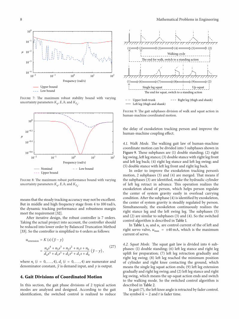
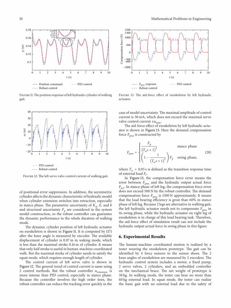