research article a new proposed return guide vane for
TRANSCRIPT

Hindawi Publishing CorporationInternational Journal of Rotating MachineryVolume 2013, Article ID 683713, 11 pageshttp://dx.doi.org/10.1155/2013/683713
Research ArticleA New Proposed Return Guide Vane for Compact MultistageCentrifugal Pumps
Qihua Zhang,1 Weidong Shi,1 Yan Xu,1 Xiongfa Gao,1
Chuan Wang,1 Weigang Lu,1 and Dongqi Ma2
1 National Research Center of Pumps and Pumping System Engineering and Technology, Jiangsu University, Zhenjiang 212013, China2 Fujian Academy of Mechanical Sciences, Fuzhou, Fujian 350005, China
Correspondence should be addressed to Qihua Zhang; [email protected]
Received 5 April 2013; Accepted 18 July 2013
Academic Editor: J.-C. Han
Copyright © 2013 Qihua Zhang et al. This is an open access article distributed under the Creative Commons Attribution License,which permits unrestricted use, distribution, and reproduction in any medium, provided the original work is properly cited.
For widely used multistage centrifugal pumps, their former structures are so bulky that nowadays growing interest has been shiftedto the development of more compact structures. Following this trend, a compact pump structure is provided and analysed. Tomaintain the pump’s pressure recovery, as well as to meet the water flow from the impeller, a circumferential twisted return guidevane (RGV) is proposed. To validate this designmethod, the instantaneous CFD simulations are performed to investigate the rotor-stator interventions. Within the impeller, the pressure fluctuation is cyclic symmetry, where the impeller frequency dominates. Atthe zone where flow leaves impeller for RGV, the pressure fluctuation is nonperiodic, the impeller frequency is major, and therotation frequency is secondary. Within RGV, the periodic symmetric fluctuation is recovered, where the rotation frequency isgoverning. The fluctuation decreases from seven cycles within impeller to two cycles within RGV, indicating that the flow fromimpeller is well handled by RGV. To examine the pump’s performance, a prototype multistage pump is designed.The testing showsthat the pump efficiency is 57.5%, and the stage head is 9m, which is comparable to former multistage centrifugal pumps. And thisdesign is more advantageous in developing compact multistage centrifugal pumps.
1. Introduction
Tomeet variable flow angles into gas turbines, hydraulic run-ners, and so forth, inlet guide vane (IGV) is adopted to keepthem operating at peak performance [1–5]. For compressors,fans, pumps, and so forth, IGV is also used to manipulatetheir operating load [6–11]. Outlet guide vane (OGV) isheavily used at downstream of low pressure turbines, fans,compressors, and pumps, where the rotating velocity canbe effectively transformed to static pressure, reducing flow-induced vibration and noise [12–19]. Nozzle guide vane(NGV) is widely used in turbines. More specially, returnguide vane (RGV) is applied for multistage centrifugal turbo-machines, where RGV is functioned as an OGV with respectto its upstream stage; meanwhile, it is served as an IGV withrespect to its downstream stage, which increases its designcomplexity [20–23].
In the first place, a suitable guide vane design is criticalfor overall stage performance. For IGV and OGV, flow in
a mainstream direction is concerned, so airfoil is widelyadopted in the streamwise direction, while in the spanwisedirection, such strategies as free-vortex method, forced-vortex method, and radial-equilibriummethod are available.To improve the performance of an impulse turbine, a free-vortex method was used to design a 3D IGV [1, 2], whichachieved a 4.5% efficiency growth. And through a dual-curvature shape technique, an IGV of minihydraulic bulbturbines was proposed, which was validated by prototypeturbine tests [3].
In early times, experimental testings were conducted todetermine the effects of guide vanes on pump performance.And through comparisons of four guide vane arrangementsin terms of pressure head, efficiency, and velocity distribu-tions, it was concluded that RGV played a more crucial rolein their multistage pump [20]. With technology advance-ment, especially with increasing CFD involvement sincethe 1980s, optimization has been popular in contemporaryturbomachine design [24]. And especially for multistage

2 International Journal of Rotating Machinery
turbomachines, the focus is the interaction between the rotorand the stator [25]. And sliding mesh technique was usedto examine different flow patterns within a multistage pumpby [26]. Moreover, rotor-stator interactions were investigatedto aid in their design optimizations. By using a rotor-statorshear system, the drop size distribution of emulsification isnumerically examined, and it was found that the effectiveequilibrium drop size was dominated by the rotor shape andits rotating speed [27]. Different combinations of flat typeblade and curved-type blade in turbomolecular pumps werenumerically investigated with DSMC, and the flat-curvedrotor-stator combination was found to be more efficient [28].The effect of the guide plate on the cavitation erosion on thebottom surface of the guide vane in three Gorges turbine wasnumerically investigated, and a new vortex structure clarify-ing this erosion was identified by the numerical simulation,which would be used to design antierosion guide plates [29].
On the other hand, optimal strategy research plays animportant role in the turbomachine optimization design. Amultiobjective method was performed to optimize a helico-axial pump impeller shape [30]. Monitoring and controllingstrategy is an alternative procedure which can be calibratedto manage energy consumption of overall turbomachinesystems. Commonly, this is an interdisciplinary and interde-partmental task. And a wide range of statistical investigationswere performed upon a large number of pumps in plants topursue energy saving [31]. And some monitoring techniqueshave been developed to improve existing pumping systemefficiency [32].
Though multistage centrifugal pumps are not so widelyapplied as turbines, fans, they are indispensable in the deepwell water and oil pumping and occupy a considerablemarketshare of household water supply, rural drainage, and urbanwater circulation. So light weight and mobility are the mostimportant factors concerned by the customers, challengingthe former structure of multistage centrifugal pumps [33]. Inthis study, the difference between former pump structure andcompact pump structure is firstly analyzed. And the merit ofcompact structure is addressed. Then, a new RGV design isproposed to match this compact structure. And the instan-taneous rotor-stator interactions are conducted to evaluateRGVperformance. Finally, a prototypemultistage centrifugalpump is designed and tested to validate the design strategy.
2. RGV Structure Study
Due to inertia, fluid discharged from the impeller trailingedge is ongoing with high rotating speed. But in the ductedpumps, the circumferential velocity is useless. And RGV iscommonly installed at downstream to recover this rotatingvelocity.There are two representative structures.Thefirst typeis widely used in boiler water feeding and power plant watercirculations, where the stages are cascaded as depicted inFigure 1(a). The RGV blade structure is commonly designedto be cylindrical, as shown in Figures 1(b) and 1(c).
The second type is commonly used in oil drilling andrural and urban water supply from underground deepwells, so it is also called multistage submersible pump or the
deep-well pump. As shown in Figure 1(e), the RGV bladestructure is twisted like a bowl.
2.1. Structure Analysis. A compact stage for submersiblepumps was proposed independently by [34, 35], where theimpeller outer diameter is nearly equal to the casing diameter,increasing its stage head. To illustrate the difference betweenformer structure and compact structure, a structure com-parison is depicted in Figure 2. Herein, the compact stagemeans removing the radial diffuser; thus, it can be speculatedthat there are two extreme cases as depicted in Figures 2(b)and 2(c). For special case I, the impeller diameter 𝐷
21is not
changed, and the casing diameter𝐷31shrinks to 𝐷
32, and its
radial size is greatly reduced. For special case II, the casingdiameter 𝐷
31is not changed, and the impeller diameter 𝐷
21
is increased to𝐷22, and its head is theoretically multiplied by
a factor (𝐷22/𝐷21)2; thus, less stages are needed and its axial
size is shortened. So compact also means saving cost.On the other hand, the special RGV also is an alternative
to the bowl-shaped RGV from the cost saving aspect. But thisis beyond our current research and would be regarded in thefuture.
2.2. Compact Stage Design. To extract oil or water from deepwells, the pump structure must be carefully tailored to utilizethe limited space in well bore. In our early work [35], a com-pact deep-well pump was developed, as shown in Figure 3.
This pump has only three stages, but it’s performanceexceeds the former multistage pump with five stages. To pro-mote its popularity and to replace former multistage pumps,it is essential to establish a set of mature design procedures,especially for RGV. Though such efforts as steady-state sim-ulation and experimental testing have been conducted toimprove its hydraulic performance, cylindrical blade shapegenerally impedes through flow performance of RGV [36–39], as well as its pressure recovery.This point can be demon-strated by the principles of centrifugal pumps [40], whereflow angles are varied along the leading edge to reduce theincidence loss.Therefore, a new circumferential twisted guidevane is proposed to tackle this problem.
3. A New RGV Structure
3.1. Twisted Blade Design Principle. A new RGV structure isdeveloped by three streamlines at different spanwise position.As shown in Figure 4(a), by fixing the top streamline 𝑐,extending the mid span streamline 𝑏 along the circumferen-tial direction and further extending the bottom streamline 𝑎forward, a triple-streamline surface is constructed, where thethree streamlines are drawn by our in-house code NQSJ [41],which is a general purpose RGV profile design tool. Then bycutting off the triangle block 𝐴𝐵𝐶 from the round plate, achannel passage is formed, as shown in Figure 4(a).
Further, as shown in Figure 4(b), the blade is combinedby two joined parts: a cylindrical part 𝐺𝐻𝐼𝐽 and a twistedpart 𝐷𝐸𝐹𝐺𝐻. Then, a practical RGV is formed as shown inFigure 4(c). Therefore, the key point is to establish the threestreamlines 𝑎, 𝑏, 𝑐 and the dividing point 𝐺, which will bediscussed hereafter.

International Journal of Rotating Machinery 3
Return guide vaneRadial diffuser
(a) (b) (c)
Bowl-shapedreturn guide
vane
(d) (e)
Figure 1: Two multistage pumps: (a) multistage pump equipped with radial diffuser and RGV, (b) radial diffuser, (c) RGV, (d) multistagepump equipped with bowl-shaped RGV, and (e) bowl-shaped RGV.
D21
D31
(a)
D32
(b)
D22
(c)
Figure 2: Structure comparison: (a) former structure, (b) special case I, and (c) special case II.
3.2. Twisted Blade Design Procedure. Herein, it is assumedthat the impeller design has been finished. And our majorconcern is the geometric structure of the impeller discharge.Tomeet design flow rate, the impellermust be cut at the outeredge to achieve enough flow area. As shown in Figure 5, thereare two cutting proposals. The first proposal cuts the blade as
well as its hub plate, and the second proposal keeps the bladeand cuts its hub plate.
Thus, for the first cutting proposal, the effective diameterof impeller is the mean value of the shroud and the hub,𝐷
2=
(𝐷21
+ 𝐷20)/2, as depicted in Figure 5(a). And the effective
diameter for the second proposal is the shroud diameter,

4 International Journal of Rotating Machinery
Suction ductImpeller Discharge valve
Guide vane
(a) (b)
Figure 3: A multistage pump with compact stages: (a) assembly and (b) RGV.
a b cabcA
BC
(a)
D
H
JI
G
EF
(b)
(c)
Figure 4: Blade design procedure: (a) schematic of a new RGV, (b) two parts of RGV, and (c) 3D view.
b2
D2 D20
D21
(a)
b2
D20D2
(b)
Figure 5: Two cutting proposals: (a) cutting blade outer edge and hub plate and (b) keeping blade and cutting hub plate.

International Journal of Rotating Machinery 5
15141210
8642015
14121086420a b c
a b c
d
o
d
R4
R5 b4
(a)
b
a
b
ccc
ooo
dd
R4
R4
R4
R5R
5R5
(b)
Figure 6: Blade profile drawing procedure: (a) blade angle distribution profiles and (b) blade profiles.
Figure 7: Schematic of 125QSJ10 and its impeller and RGV.
as shown in Figure 5(b). Then, the outer diameter of RGVis 𝐷4∈ [1.03, 1.08]𝐷
2. And the inlet meridional velocity at
leading edge of RGV is
V𝑚3
=4𝑄
𝜋 (𝐷2
2− 𝐷20
2). (1)
And the circumferential velocity at leading edge of RGVis
V𝑢3
=𝑔𝐻/𝜂
ℎ
𝑢2
, (2)
where 𝜂ℎis the impeller hydraulic efficiency, which is assu-
med to be known.Thus, with the meridional velocity V𝑚3
andcircumferential velocity V
𝑢3, the RGV inlet flow angle at the
streamline 𝑎 is
𝛼3𝑎
= arctan(V𝑚3
V𝑢3
) . (3)
With circumferential velocity decreasing, the inlet flowangle at streamline 𝑏 and 𝑐 is increased gradually. As the flowfield information within RGV is insufficient, it is presumedthat 𝛼
3𝑏= 𝛼3𝑎+ const, and 𝛼
3𝑐= 𝛼3𝑏+ const, where the const
can be revised at design stage. Similarly, the RGV outlet angleis presumed to be at 𝛼
4∈ [45
∘, 90∘], the wrap angle is at
𝜙 ∈ [60∘, 130∘], and the RGV blade height 𝑏
4∈ [1.05, 1.4]𝑏
2.
These parameters are flexible at design stage, which can beadjusted via the GUI of our in-house code NQSJ [41]. Withthese structural parameters, it is ready to draw the bladeprofile.
The profile drawing procedure is similar to the designof impeller blades [40]. Firstly, the blade angle distributionprofile from inlet angle 𝛼
3to outlet angle 𝛼
4is constructed by
a Bezier curve as plotted in Figure 6(a), where 𝑎, 𝑏, 𝑐 represent
Table 1: Design parameters of impeller.
𝑄 (m3/h) 𝐻 (m) 𝑛 (r/min) 𝑍𝐼
𝐷21(mm) 𝐷
20(mm) 𝑏
2(mm)
10 8.5 2850 7 103 98 8
Table 2: Design parameters of RGV.
𝑍𝑅
𝐷4(mm) 𝐵
4(mm) 𝛼
3𝑎(∘) 𝛼
3𝑏(∘) 𝛼
3𝑐(∘) 𝛼
4(∘) 𝜙 (∘)
6 105 10 10 13.5 16.5 65 75
the blade angle distribution profile of three streamlines and 𝑑
represents the dividing point. And the cubic Bezier curve is
Bez (𝑠) = 𝑃0(1 − 𝑠)
3+ 3𝑃1𝑠(1 − 𝑠)
2
+ 3𝑃2𝑠2(1 − 𝑠) + 𝑃
3𝑠3, 𝑠 ∈ [0, 1] ,
(4)
where 𝑃0represents the inlet point, that is, points 𝑎, 𝑏, and
𝑐, and 𝑃3represents the outlet point, that is, point 𝑜, as
shown in Figure 6(a). 𝑃1and 𝑃
2are auxiliary points which
are controlled by NQSJ. With the angle distribution profiles,the corresponding blade profiles are plotted point by point asshown in Figure 6(b).
4. Instantaneous Rotor-StatorInteraction Analysis
4.1. Pump Configurations. To examine the new RGV designmethod, a prototype pump 125QSJ10 is designed, whichmeans the pump is used in a 125mm (4 inch) deep well. Theimpeller discharge is cut using the first proposal. The majordesign parameters are listed in Tables 1 and 2.
To shorten design cycle, a hydraulic design system NQSJ[40] is heavily used in the blade design and optimizationprocedures. And the main structure and such hydrauliccomponents as impeller and RGV are depicted in Figure 7.

6 International Journal of Rotating Machinery
Interface 1Interface 2Interface 3
Interface 4
Stage 1 Stage 2 Discharge pipeSuction pipe
Figure 8: Dual-stage calculation model and numerical grids.
4.2. Numerical Configuration
4.2.1. Basic Equations. For incompressible flows, mass con-servation equation is
𝜕𝜌
𝜕𝑡+ ∇ ⋅ (𝜌u) = 0. (5)
For flows under noninertial rotating frame, momentumconservation equation is
𝜕 (𝜌u)𝜕𝑡
+ ∇ ⋅ (𝜌𝑢u) + 𝜌 [2𝜔 × u + 𝜔 × 𝜔 × r]
= −∇𝑝 + ∇ ⋅ 𝜎,
(6)
where𝜎 = 𝜇(𝜕V𝑖/𝜕𝑥𝑗+𝜕V𝑗/𝜕𝑥𝑖), 2𝜔×u represents the Coriolis
force and 𝜔 × 𝜔 × r represents centrifugal force. Andthe previous equations applies for the multistage centrifugalpumps.
The RNG 𝑘-𝜀model is used for treatment of turbulence:
𝜕𝑘
𝜕𝑡+ 𝑢𝑖
𝜕𝑘
𝜕𝑥𝑖
=𝜕
𝜕𝑥𝑗
[𝛼𝑘
𝜇eff𝜌
𝜕𝑘
𝜕𝑥𝑗
]
+𝜇𝑡
𝜌[𝜕𝑢𝑖
𝜕𝑥𝑗
+
𝜕𝑢𝑗
𝜕𝑥𝑖
]𝜕𝑢𝑖
𝜕𝑥𝑗
− 𝜀,
𝜕𝜀
𝜕𝑡+ 𝑢𝑖
𝜕𝜀
𝜕𝑥𝑖
=𝜕
𝜕𝑥𝑗
[𝛼𝜀
𝜇eff𝜌
𝜕𝜀
𝜕𝑥𝑗
]
+ 𝐶1𝜀
𝜀
𝑘
𝜇𝑡
𝜌[𝜕𝑢𝑖
𝜕𝑥𝑗
+
𝜕𝑢𝑗
𝜕𝑥𝑖
]𝜕𝑢𝑖
𝜕𝑥𝑗
− 𝐶∗
2𝜀
𝜀2
𝑘,
𝐶∗
2𝜀= 𝐶2𝜀+
𝐶𝜇𝜂3(1 − 𝜂/𝜂
0)
1 + 𝛽𝜂3,
(7)
where 𝜇eff = 𝜇 + 𝜇𝑡represents effective viscosity, and
𝜇𝑡
= 𝜌𝐶𝜇(𝑘2/𝜀) represents turbulent viscosity. And 𝜂 =
[2𝑆𝑖𝑗⋅ 𝑆𝑖𝑗]1/2
(𝑘/𝜀), where 𝑆𝑖𝑗
= (1/2)[𝜕𝑢𝑖/𝜕𝑥𝑗+ 𝜕𝑢𝑗/𝜕𝑥𝑖] is
fluid strain rate. And the model related constants are 𝐶𝜇=
0.0845, 𝛼𝑘= 𝛼𝜀= 1.393, 𝐶
1𝜀= 1.42, 𝐶
2𝜀= 1.68, 𝜂
0= 4.38,
and 𝛽 = 0.012. To date, a better choice of turbulence modelfor rotating flow within turbomachines is still not available.
Table 3
Number of cells Stage head (m) Error (%)700,584 10.173 5.081,300,745 9.982 2.9071,510,374 9.958 2.66
P4
P3
P6 P7
P9
P10P1
Figure 9: Pressure monitoring positions.
Relatively, the application of RNG 𝑘-𝜀 model receives moresupport, as well as its accuracy.
4.2.2. CFD Setup. The calculation model is set up in thecommercial package Ansys FLUENT to perform the simu-lation. A dual-stage calculation model is built to evaluate itsperformance. And there are four sets of interfaces betweenthe stationary parts and the rotating parts, as shown inFigure 8.
Themean velocity inlet boundary condition is prescribedon the suction, where the velocity is 𝑈suc = 4𝑄/𝜋(𝐷
1
2−
𝐷ℎ
2), 𝐷1is the impeller suction diameter, and 𝐷
ℎis the
impeller hub diameter. And the flow at discharge is supposedto be fully developed, so the Neumann boundary condition𝜕𝜑/𝜕𝑛 = 0 is imposed, 𝜑 represents such unknown variablesas velocity, pressure, and turbulence scalars. No-slip bound-ary condition is imposed on the impeller and the guide vanewall boundaries, where 𝜑 = 0. And the turbulent flows aresimulated by the RNG 𝑘-𝜀 model and the wall function fornear wall treatment.
4.2.3. Grid Irrelevance Analysis. The numerical mesh wasgenerated by Ansys ICEM, where yplus ∈ [30, 150]. Then,the steady-state simulation is performed to achieve such

International Journal of Rotating Machinery 7
0.000 0.005 0.010 0.015 0.020 0.025
−0.3
−0.2
−0.1
0.0
0.1
t(s)
P1P2
Cp
(a)
0.000 0.005 0.010 0.015 0.020 0.025
−0.24
−0.16
−0.08
0.00
0.08
t(s)
P3P4P5
Cp
(b)
0.000 0.005 0.010 0.015 0.020 0.025−0.06
−0.04
−0.02
0.00
0.02
0.04
t(s)
P6P7
Cp
(c)
0.000 0.005 0.010 0.015 0.020 0.025−0.02
−0.01
0.00
0.01
0.02
t(s)
P8P9P10
Cp
(d)
Figure 10: Pressure fluctuation at different locations: (a) impeller leading edge, (b) impeller trailing edge, (c) RGV leading edge, and (d)within RGV.
time-averaged characteristics as pump head, torque and effi-ciency. The stage head is
𝐻 =
(𝑃totdis − 𝑃totsuc)
𝜌𝑔, (8)
where 𝑃totdis represents the stage total pressure at dischargeand 𝑃totsuc represents the stage total pressure at suction. Andthe stage efficiency is
Eff =𝜌𝑔𝐻𝑄
𝑀𝜔. (9)
With steady-state simulations, the grid irrelevance isexamined at three grid levels. And the obtained stage headand its estimated error are listed in Table 3.
So in the present study, the magnitude of mesh size isaround 1,500,000; thus, the grid irrelevance can be guaran-teed.
4.3. Rotor-Stator Interaction. Instantaneous rotor-stator int-eraction rather than steady-state flow field reveals the real-time flow situation. Herein, the sliding mesh is used for therotor-stator interaction analysis. And the pressure coefficientis used to evaluate its fluctuation as follows:
𝐶𝑝=
𝑝 − 𝑝
𝜌𝑢2
2/2, (10)
where 𝑝 is the averaged pressure within a rotation and 𝑢2is
the impeller wheel velocity.As shown in Figure 9, pressure monitorings are conduct-
ed at ten different positions within the impeller and RGV.In Figures 10(a) and 10(b), with blade perturbation, the
pressure fluctuation is formed within the impeller. It is cyclicsymmetric at the leading edge. Inherently, the fluctuationruns seven peaks and valleys, equaling to the number ofblades. And gradually, it is deviated from the cyclic symmetry

8 International Journal of Rotating Machinery
0 500 1000 1500 2000 2500
0.00
0.01
0.02
0.03
0.04
0.05
Frequency (Hz)
P1
P2
Cp
(a)
0 500 1000 1500 2000 2500
0.000
0.005
0.010
0.015
0.020
Frequency (Hz)
P3
P4
P5
Cp
(b)
0 500 1000 1500 2000 2500
0.000
0.002
0.004
0.006
0.008
0.010
Frequency (Hz)
P6
P7
Cp
(c)
0 500 1000 1500 2000 2500
0.0000
0.0006
0.0012
0.0018
0.0024
0.0030
Frequency (Hz)
P8
P9
P10
Cp
(d)
Figure 11: Frequency spectra at different locations: (a) impeller leading edge, (b) impeller trailing edge, (c) RGV leading edge, and (d) withinRGV.
by the intervention of RGV. With water outflowing fromimpeller, the fluctuation appears to be abnormal, as shownin Figure 10(c). But with the renormalization of RGV, itreappears cyclic, but only two peaks and valleys are retainedas shown in Figure 10(d).
The frequency spectra are shown in Figure 11, which areobtained by FFT transformations. For multistage pumps, theimpeller frequency is
𝑓𝐼=
𝑛𝑍𝐼
60. (11)
Substitute 𝑛 = 2850 (r/min), 𝑍𝐼
= 7, into (10), 𝑓𝐼is
332.5Hz. In impeller, as above the fluctuation frequency isdominated by the impeller frequency, that is, 332.5Hz, asshown in Figures 11(a) and 11(b). With water outflowing fromthe impeller, the impeller frequency is even pronounced, buta secondary frequency appears with magnitude 𝑛/60, that is,47.5Hz, which is the rotation frequency, as shown in Fig-ure 11(c).Within RGV, the rotation frequency dominates, andthe impeller frequency becomes the secondary frequency, asshown in Figure 11(d).
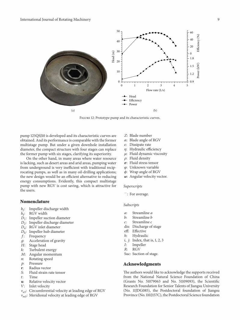
4.4. Prototype Pump Testing. To verify the previous designstrategies, a four-stage pump is designed and tested.The test-ing is conducted at the pump test rig of the FujianAcademy of
Mechanical Sciences. And the stage-averaged performance,such as the flow rate versus head and the flow rate versusefficiency curves are plotted in Figure 12.
In Figure 12, the results show that the peak efficiencyis 57.5%, and the stage head is 9m. And its efficiency iscomparable to former multistage pumps, while commonlythe stage head of former multistage pump is near 6.5m. Sothe more head is needed, the greater cost-saving potential itwill produce.
5. Conclusions
In this study, a compact structure is put forward and com-pared with the former structure of multistage centrifugalpumps. It is evident that its light weight and mobility willattract more prospective users. To meet this compact struc-ture, a new RGV design is proposed. By using a triple-streamline surface shaping, a circumferential twisted RGV isdeveloped.
To validate this design, the instantaneous rotor-statorinteractions are investigated using the sliding mesh. Andthe pressure fluctuations are analyzed. The results show thatthe maximum fluctuation appears at the leading edge ofRGV. And at the trailing edge of RGV the fluctuation isalmost negligible. To check validity of this design, a prototype
International Journal of Rotating Machinery 9
(a)
50
40
30
20
10
00 1 2 3 4 5
Flow rate (L/s)
Hea
d (m
)
Head
Pow
er (k
W)
Power
Effici
ency
(%)
Efficiency
60
40
20
01.8
1.5
1.2
0.9
(b)
Figure 12: Prototype pump and its characteristic curves.
pump 125QSJ10 is developed and its characteristic curves areobtained. And its performance is comparable with the formermultistage pump. But under a given downhole installationdiameter, the compact structure with four stages can replacethe former pump with six stages, clarifying its superiority.
On the other hand, in many areas where water resourceis lacking, such as desert areas and arid areas, pumping waterfrom underground is very inefficient with traditional recip-rocating pumps, as well as in many oil-drilling applications;the new design would be an efficient alternative to reducingenergy consumptions. Evidently, this compact multistagepump with new RGV is cost saving, which is attractive forthe users.
Nomenclature
𝑏2: Impeller discharge width
𝑏4: RGV width
𝐷1: Impeller suction diameter
𝐷2: Impeller discharge diameter
𝐷4: RGV inlet diameter
𝐷ℎ: Impeller hub diameter
𝑓: Frequency𝑔: Acceleration of gravity𝐻: Stage head𝑘: Turbulent energy𝑀: Angular momentum𝑛: Rotating speed𝑝: Pressurer: Radius vector𝑆: Fluid strain rate tensor𝑡: Timeu: Relative velocity vector𝑉: Inlet velocityV𝑢3: Circumferential velocity at leading edge of RGV
V𝑚3: Meridional velocity at leading edge of RGV
𝑍: Blade number𝛼: Blade angle of RGV𝜀: Dissipate rate𝜂: Hydraulic efficiency𝜇: Fluid dynamic viscosity𝜌: Fluid density𝜎: Fluid stress tensor𝜑: Unknown variable𝜙: Wrap angle of RGV𝜔: Angular velocity vector.
Superscripts—: For average.
Subscripts
𝑎: Streamline 𝑎𝑏: Streamline 𝑏𝑐: Streamline 𝑐dis: Discharge of stageeff: Effectiveℎ: Hydraulic𝑖, 𝑗: Index, that is, 1, 2, 3𝐼: Impeller𝑅: RGVSuc: Suction of stage.
Acknowledgments
The authors would like to acknowledge the supports receivedfrom the National Natural Science Foundation of China(Grants No. 51079063 and No. 51109093), the ScientificResearch Foundation for Senior Talents of Jiangsu University(No. 11JDG085), the Postdoctoral foundation of JiangsuProvince (No. 1102157C), the Postdoctoral Science foundation

10 International Journal of Rotating Machinery
of China (No. 2013M531282), and the National Key Technol-ogy R&DProgram of theMinistry of Science and Technologyof China (No. 2011BAF14B01).
References
[1] A. Thakker, T. S. Dhanasekaran, and J. Ryan, “Experimentalstudies on effect of guide vane shape on performance of impulseturbine for wave energy conversion,” Renewable Energy, vol. 30,no. 15, pp. 2203–2219, 2003.
[2] A. Thakker and T. S. Dhanasekaran, “Computed effect of guidevane shape on performance of impulse turbine for wave energyconversion,” International Journal of Energy Research, vol. 29,no. 13, pp. 1245–1260, 2005.
[3] L. M. C. Ferro, L. M. C. Gato, and A. F. O. Falcao, “Design andexperimental validation of the inlet guide vane system of a minihydraulic bulb-turbine,” Renewable Energy, vol. 35, no. 9, pp.1920–1928, 2010.
[4] M. Govardhan and T. S. Dhanasekaran, “Effect of guide vaneson the performance of a self-rectifying air turbine with constantand variable chord rotors,” Renewable Energy, vol. 26, no. 2, pp.201–219, 2002.
[5] Q. Li, H. Quan, R. Li, and D. Jiang, “Influences of guide vanesairfoil on hydraulic turbine runner performance,” inProceedingsof the International Conference on Modern Hydraulic Engineer-ing (CMHE ’12), pp. 703–708, Nanjing, China, March 2012.
[6] A. Mohseni, E. Goldhahn, R. A. Van den Braembussche, and J.R. Seume, “Novel IGV designs for centrifugal compressors andtheir interaction with the impeller,” Journal of Turbomachinery,vol. 134, no. 2, Article ID 021006, 8 pages, 2012.
[7] S. L. Gunter, S. A. Guillot, W. F. Ng, and S. T. Bailie, “A three-dimensional CFD design study of a circulation control inletguide vane for a transonic compressor,” in Proceedings of the54th ASME Turbo Expo 2009, pp. 91–101, Orlando, Fla, USA,June 2009.
[8] M.Hensges, “Simulation and optimization of an adjustable inletguide vane for industrial turbo compressors,” in Proceedings ofthe 53rd ASME Turbo Expo 2008, pp. 11–20, Berlin, Germany,June 2008.
[9] M. Coppinger and E. Swain, “Performance prediction of anindustrial centrifugal compressor inlet guide vane system,”Proceedings of the Institution ofMechanical Engineers A, vol. 214,no. 2, pp. 153–164, 2000.
[10] J. Fukutomi and R. Nakamura, “Performance and internal flowof cross-flow fan with inlet guide vane,” JSME InternationalJournal B, vol. 48, no. 4, pp. 763–769, 2005.
[11] W. K. Chan, Y. W. Wong, S. C. M. Yu, and L. P. Chua, “Acomputational study of the effects of inlet guide vanes on theperformance of a centrifugal blood pump,” Artificial Organs,vol. 26, no. 6, pp. 534–542, 2002.
[12] V. Chernoray, S. Ore, and J. Larsson, “Effect of geometrydeviations on the aerodynamic performance of an outlet guidevane cascade,” in Proceedings of the ASME Turbo Expo 2010:Power for Land, Sea, and Air, pp. 381–390, Glasgow, UK, June2010.
[13] T. Sonoda and H. Schreiber, “Aerodynamic characteristics ofsupercritical outlet guide vanes at low Reynolds number condi-tions,” Journal of Turbomachinery, vol. 129, no. 4, pp. 694–704,2007.
[14] H. Posson, S. Moreau, and M. Roger, “Broadband noise predic-tion of fan outlet guide vane using a cascade response function,”
Journal of Sound and Vibration, vol. 330, no. 25, pp. 6153–6183,2011.
[15] C. Clemen, “Aero-mechanical optimisation of a structural fanoutlet guide vane,” Structural and Multidisciplinary Optimiza-tion, vol. 44, no. 1, pp. 125–136, 2011.
[16] A. G. Barker and J. F. Carrotte, “Influence of compressor exitconditions on combustor annular diffusers, part 1: diffuserperformance,” Journal of Propulsion and Power, vol. 17, no. 3, pp.678–685, 2001.
[17] V. Cyrus and J. Polansky, “Numerical simulation of the flowpulsations origin in cascades of the rear blade rows in a gasturbine axial compressor using low calorific fuel,” Journal ofTurbomachinery, vol. 132, no. 3, Article ID 031012, 11 pages, 2010.
[18] D. Kaya, “Experimental study on regaining the tangentialvelocity energy of axial flow pump,” Energy Conversion andManagement, vol. 44, no. 11, pp. 1817–1829, 2003.
[19] W. Yan, D. Shi, Z. Luo, and Y. Lu, “Three-dimensional CFDstudy of liquid-solid flow behaviors in tubular loop polymer-ization reactors: the effect of guide vane,” Chemical EngineeringScience, vol. 66, no. 18, pp. 4127–4137, 2011.
[20] A. Sulaiman and S. Gabin, “Flow through the return channelof a multistage centrifugal pump,” in Proceedings of the 5thConference on Fluid Machinery, vol. 2, pp. 1121–1132, AkademiaiKiado, Budapest, Hungary, 1975.
[21] S. Konig and N. Petry, “Parker-type acoustic resonances inthe return guide vane cascade of a centrifugal compressor—theoreticalmodeling and experimental verification,” inProceed-ings of the ASME Turbo Expo 2010: Power for Land, Sea, and Air,pp. 1687–1700, Glasgow, UK, June 2010.
[22] M.Miyano, T. Kanemoto, D. Kawashima, A.Wada, T. Hara, andK. Sakoda, “Return vane installed in multistage centrifugalpump,” The International Journal of Fluid Machinery and Sys-tems, vol. 1, no. 1, pp. 57–63, 2008.
[23] D. Kawashima, T. Kanemoto, K. Sakoda et al., “Matching dif-fuser vane with return vane installed in multistage centrifugalpump,” The International Journal of Fluid Machinery and Sys-tems, vol. 1, no. 1, pp. 86–91, 2008.
[24] J. D. Denton, “Some limitations of turbomachinery CFD,” inProceedings of the ASME Turbo Expo 2010: Power for Land, Sea,and Air, pp. 1–11, Glasgow, UK, June 2010.
[25] T. Nagahara and Y. Inoue, “Investigation of hydraulic design forhigh performancemulti-stage pump using CFD,” in Proceedingsof the ASME Fluids Engineering Division Summer Conference(FEDSM ’09), pp. 417–424, Vail, Colo, USA, August 2009.
[26] S. Huang, A. A. Mohamad, and K. Nandakumar, “Numericalsimulation of unsteady flow in a multistage centrifugal pumpusing sliding mesh technique,” Progress in Computational FluidDynamics, vol. 10, no. 4, pp. 239–245, 2010.
[27] T. L. Rodgers and M. Cooke, “Rotor-stator devices: the role ofshear and the stator,”Chemical Engineering Research andDesign,vol. 90, no. 3, pp. 323–327, 2012.
[28] N. Sengil, “Performance increase in turbomolecular pumpswith curved type blades,”Vacuum, vol. 86, no. 11, pp. 1764–1769,2012.
[29] T. Chen and S. C. Li, “Numerical investigation of guide-plateinduced pressure fluctuations on guide vanes of three gorgesturbines,” Journal of Fluids Engineering, vol. 133, no. 6, ArticleID 061101, 10 pages, 2011.
[30] J. Zhang, H. Zhu, C. Yang, Y. Li, and H. Wei, “Multi-objectiveshape optimization of helico-axial multiphase pump impellerbased on NSGA-II and ANN,” Energy Conversion and Manage-ment, vol. 52, no. 1, pp. 538–546, 2009.

International Journal of Rotating Machinery 11
[31] D. Kaya, E. A. Yagmur, K. S. Yigit, F. C. Kilic, A. S. Eren, and C.Celik, “Energy efficiency in pumps,” Energy Conversion andManagement, vol. 49, no. 6, pp. 1662–1673, 2008.
[32] S. Sallem, M. Chaabene, and M. B. A. Kamoun, “Optimumenergy management of a photovoltaic water pumping system,”Energy Conversion and Management, vol. 50, no. 11, pp. 2728–2731, 2009.
[33] M. Golcu, Y. Pancar, and Y. Sekmen, “Energy saving in a deepwell pump with splitter blade,” Energy Conversion and Manage-ment, vol. 50, no. 11, pp. 2728–2731, 2009.
[34] H. Roclawski and D.-H. Hellmann, “Rotor-stator-interaction ofa radial centrifugal pump stage with minimum stage diameter,”in Proceedings of the 4th WSEAS International Conferenceon Fluid Mechanics and Aerodynamics, pp. 301–308, Elounda,Greece, 2006.
[35] W. Shi, Q. Zhang, and W. Lu, “Hydraulic design of new-typedeep well pump and its flow calculation,” Journal of JiangsuUniversity, vol. 27, no. 6, pp. 528–531, 2006 (Chinese).
[36] H. Roclawski and D.-H. Hellmann, “Numerical simulation of aradial multistage centrifugal pump,” in Proceedings of the 44thAIAA Aerospace Sciences Meeting and Exhibit, AIAA2006-1428,Elounda, Greece, January 2006.
[37] H. Roclawski, A. Weiten, and D.-H. Hellmann, “Numericalinvestigation and optimization of a stator for a radial submer-sible pump stage with minimum stage diameter,” in Proceedingsof the ASME Joint U.S.-European Fluids Engineering DivisionSummer Meeting (FEDSM ’06), FEDSM2006-98181, pp. 233–243, Miami, Fla, USA, July 2006.
[38] W. Shi, W. Lu, H. Wang, and Q. Li, “Research on the theoryand design methods of the new type submerible pump for deepwell,” in Proceedings of the ASME Fluids Engineering DivisionSummer Conference (FEDSM ’09), pp. 91–97, Vail, Colo, USA,August 2009.
[39] L. Zhou, W. D. Shi, W. G. Lu et al., “Numerical investigationsand performance experiments of a deep-well centrifugal pumpwith different diffusers,” Journal of Fluids Engineering, vol. 134,no. 7, Article ID 071102, 8 pages, 2012.
[40] J. F. Gulich, Centrifugal Pumps, Springer, New York, NY, USA,2007.
[41] Q. H. Zhang, Y. Xu,W. D. Shi et al., “Research and developmenton the hydraulic design system of the guide vanes of multistagecentrifugal pumps,” Applied Mechanics and Materials, vol. 197,pp. 24–30, 2012.

International Journal of
AerospaceEngineeringHindawi Publishing Corporationhttp://www.hindawi.com Volume 2014
RoboticsJournal of
Hindawi Publishing Corporationhttp://www.hindawi.com Volume 2014
Hindawi Publishing Corporationhttp://www.hindawi.com Volume 2014
Active and Passive Electronic Components
Control Scienceand Engineering
Journal of
Hindawi Publishing Corporationhttp://www.hindawi.com Volume 2014
International Journal of
RotatingMachinery
Hindawi Publishing Corporationhttp://www.hindawi.com Volume 2014
Hindawi Publishing Corporation http://www.hindawi.com
Journal ofEngineeringVolume 2014
Submit your manuscripts athttp://www.hindawi.com
VLSI Design
Hindawi Publishing Corporationhttp://www.hindawi.com Volume 2014
Hindawi Publishing Corporationhttp://www.hindawi.com Volume 2014
Shock and Vibration
Hindawi Publishing Corporationhttp://www.hindawi.com Volume 2014
Civil EngineeringAdvances in
Acoustics and VibrationAdvances in
Hindawi Publishing Corporationhttp://www.hindawi.com Volume 2014
Hindawi Publishing Corporationhttp://www.hindawi.com Volume 2014
Electrical and Computer Engineering
Journal of
Advances inOptoElectronics
Hindawi Publishing Corporation http://www.hindawi.com
Volume 2014
The Scientific World JournalHindawi Publishing Corporation http://www.hindawi.com Volume 2014
SensorsJournal of
Hindawi Publishing Corporationhttp://www.hindawi.com Volume 2014
Modelling & Simulation in EngineeringHindawi Publishing Corporation http://www.hindawi.com Volume 2014
Hindawi Publishing Corporationhttp://www.hindawi.com Volume 2014
Chemical EngineeringInternational Journal of Antennas and
Propagation
International Journal of
Hindawi Publishing Corporationhttp://www.hindawi.com Volume 2014
Hindawi Publishing Corporationhttp://www.hindawi.com Volume 2014
Navigation and Observation
International Journal of
Hindawi Publishing Corporationhttp://www.hindawi.com Volume 2014
DistributedSensor Networks
International Journal of