research article a numerical study on a vertical-axis wind turbine with inclined … ·...
TRANSCRIPT

Research ArticleA Numerical Study on a Vertical-AxisWind Turbine with Inclined Arms
Agostino De Marco, Domenico P. Coiro, Domenico Cucco, and Fabrizio Nicolosi
Department of Industrial Engineering (DII), University of Naples Federico II, Piazzale Tecchio 80, 80125 Naples, Italy
Correspondence should be addressed to Agostino De Marco; [email protected]
Received 28 August 2013; Revised 5 March 2014; Accepted 2 April 2014; Published 30 June 2014
Academic Editor: W. W. Liou
Copyright © 2014 Agostino De Marco et al. This is an open access article distributed under the Creative Commons AttributionLicense, which permits unrestricted use, distribution, and reproduction in any medium, provided the original work is properlycited.
This work focuses on a particular type of vertical-axis wind turbine, in which a number of inclined arms with airfoil-shapedcross-sections are mounted to connect the principal blades to their hub. While the majority of the known studies on vertical-axis turbines is devoted to the role of principal blades, in most of the cases without taking into account other parts of the windturbine, the objective of this work is to investigate the effect of uncommon arm geometries, such as the inclined arms.The inclinedarms are known to have a potentially beneficial role in the power extraction from the wind current but, due to the complexity ofthe phenomena, the investigation on aerodynamics of this type of turbine is often impossible through analytical models, such asblade-element momentum theory. It turns out that adequate studies can only be carried out by wind tunnel experiments or CFDsimulations.This work presents amethodical CFD study on how inclined arms can be used on a selectedwind turbine configurationto harvest additional power from the wind.The turbine configuration, geometry, and some fundamental definitions are introducedfirst. Then an in-depth CFD analysis is presented and discussed.
1. Introduction
Due to the rapid consumption of fossil fuel resources andrising general public concerns for sustainable development,wind power generation is actually one of the fastest growingindustries for renewable energy production. In addition tolarge wind farms, studies are focusing on harnessing windenergy in urban and suburban areas.
The two primary types of wind turbine today in useare horizontal axis (horizontal-axis wind turbine (HAWT))and vertical axis (vertical-axis wind turbine (VAWT))machines. VAWTs can be further divided into lift-driven (alsonamed Darrieus-type) and drag-driven (named Savonius-type) devices.
HAWTs are highly developed and used in all currentlarge scale wind farms. On the other hand, the majority ofresearch onVAWTswas carried out in the late 1970s and early1980s, till it became accepted that HAWTsweremore efficientat large scales, and interest in VAWTs was dropped out.
Only recently this kind of turbine had undergone renewinginterest, because they have indeed a number of advantagesover HAWTs: (i) VAWTs are independent on wind direction,so there is no need for a yawing mechanism; (ii) due to therelatively lower rotational speed, VAWTs are typically quieterthan HAWTs; (iii) production and maintenance costs of aVAWT can be lower than those for an equivalent HAWT.
On the other hand, aVAWThas an inherently nonstation-ary aerodynamic behavior due to the continuous variationof incidence angle and relative velocity experienced by theblades during a complete revolution. This leads, especiallyat low angular speed (low tip speed ratios), to the dynamicstall phenomenon that has significant effects on unsteadyloads acting on the blades and consequently on turbine per-formance. Moreover, every half rotation each blade actuallyworks in its ownwake as well as in other blades wakes, furtherenhancing the nonstationary behavior of the motion.
Due to the complexity of the phenomena, the investi-gation of VAWT aerodynamics is often impossible through
Hindawi Publishing CorporationInternational Journal of Aerospace EngineeringVolume 2014, Article ID 180498, 14 pageshttp://dx.doi.org/10.1155/2014/180498

2 International Journal of Aerospace Engineering
Blade
Inclined arms
Horizontal arm
(a)
H = 2.50m
HA = 2.00m
𝜑A = 30∘
R = 1.30m
Turbine axis
(b)
Figure 1: Parts and dimensions of one element of the proposed vertical-axis wind turbine with inclined arms.
analytical models, such as blade-element momentum theory[1]. It turns out that adequate studies can only be carried outby wind tunnel experiments or CFD simulations.
Recently, several authors [2–4] performed both 2D and3D numerical simulations of Darrieus micro-VAWTs. SimaoFerreira et al. [5] compared the results of two types ofRANS solutions (with Spalart-Allmaras [6] and K-Omega [7]turbulence models) and of large Eddy simulation (LES) anddetached Eddy simulation (DES) with experimental vorticityvisualization for a single-bladed VAWT. Castelli et al. [8–10]presented a fairly complete numerical study of the effect onturbine performance of different blade parameters such asairfoil asymmetry, blade inclination, and number. The sameauthors [11] proposed also an interesting turbine performanceprediction model. Amet et al. [12] performed accurate 2Dnumerical studies on the mechanism of vorticity generationin VAWTs. Hwang et al. [13] presented numerical simulationsof blade pitch control systems.
While the majority of the known studies on VAWT focuson the blade itself, in most of the cases without takinginto account other parts of a wind turbine, the presentwork objective is to investigate the effect of uncommonarm geometries of VAWT, such as the “inclined arms” (seeFigure 1). Some phenomena occurring when this configura-tion rotates in the wind are still not completely understoodnowadays. This offers the chance to investigate on how theinclined-armsVAWTcan be used to harvest additional powerfrom the wind. The Aircraft Design and AeroflightDynamicsGroup of the University Federico II Department of IndustrialEngineering (Aerospace Division) have developed severalprototypes of this kind of HAWT and VAWT [14–16]. Initialestimations obtained with vortex methods have shown goodresults, encouraging further investigation of this kind ofturbine. The present work reports a CFD analysis of selectedturbine geometry with this concept.
In the next sections the turbine configuration, geometry,and some fundamental definitions are introduced first. Thenan in-depth CFD study realized for the present work willbe presented. Finally, the principal results obtained will bediscussed.
2. Inclined-Arms Turbine Configuration
As depicted in Figure 1, the geometry of the inclined-armsconcept implies the presence of two inclined arms withairfoil-shaped cross-sections. The inclined arms are joinedto a horizontal arm that connects the blades to the hub.There are twomain advantages stemming from this particularconfiguration:
(i) the inclined arms act as additional blades; the nettorque provided by the arms per revolution at leastneutralizes their own parasite torque (due to theirdrag); and, as will be shown, additional power can beeffectively extracted;
(ii) a better distribution of mechanical loads on bladeattachments with respect to horizontal-arms turbines.
The complete turbine configuration consists of threerotating “elements” mounted on the hub. In the study pre-sented here, each element is formed by
(i) a NACA 0018 straight, untwisted vertical blade, with20mmof chord and 5∘ of pitch (outwardswith respectto the circular path of rotation, see Figure 2(b));
(ii) 2 inclined arms whose cross-section has the sameprofile of the vertical blade; their external tip isattached at some point along the vertical blade; andeach inclined arm forms a 30∘ angle with the blade;
(iii) an inner horizontal arm, with NACA 0018 profile and12mm of chord, connecting inclined arms to the hub.

International Journal of Aerospace Engineering 3
Upwind XY
Z
Downwind
Air flow
Turbine axis
AF
Ω
(a)
X
Y
O
W
L
D
W
D
LW
D
L
V = ΩR
V = ΩR
V = ΩR𝛼
𝛼
𝛼
U∞
U∞
U∞
0∘
𝜃
90∘
180∘
270∘
(b)
Figure 2: (a) Conceptual visualization of a VAWT. (b) Forces and velocities on a Darrieus turbine [5].
3. Turbine Parameters
For the discussion of results presented later in this work,some fundamental definitions have to be established. Turbinesolidity is defined as follows:
𝜎 =
𝑛𝑐
𝑅
, (1)
where 𝑛 is the number of blades and 𝑐 is the blade chord.Thetip speed ratio 𝜆 (or TSR) is given by
𝜆 =
Ω𝑅
𝑈∞
, (2)
where Ω is the turbine angular velocity and 𝑈∞
is the windvelocity.
Fromgeometric considerations, theoretical relative veloc-ity modulus𝑊 and incidence angle 𝛼 are given by
𝑊 = 𝑈∞
√1 + 2𝜆 cos 𝜃 + 𝜆2,
𝛼 = −tan−1 ( sin 𝜃cos 𝜃 + 𝜆
) ,
(3)
where the angle 𝜃 is the azimuthal position of the elementalong the revolution.The azimuthal position is zero when theelement is facing the asymptotic wind direction and grows asthe blade rotates counterclockwise (see Figures 2, 3, and 4).
The sign convention of the blade incidence angle 𝛼 is thesame of the blade pitch angle 𝛽, which is considered positivewhen the blade leading edge is rotated outwards with respectto the circular path of rotation. Then, when the azimuthalposition is zero, the incidence angle is positive if the bladehas a positive pitch.
The results discussed later in this work will be shownin terms of the turbine performance coefficient (or power
coefficient) 𝐶𝑃, which is calculated from the torque 𝑇 as
follows:
𝐶𝑃=
𝑇Ω
(1/2) 𝜌𝑈3
∞
𝐴𝐹
, (4)
where 𝐴𝐹is the rotor frontal area (2𝑅 times the blade height
ℎ).
4. A CFD Study on an Inclined-Arms VAWT
The study presented here goes straight to the numericalcalculation of the three-dimensional fluid dynamic fieldaround the rotating inclined-arms wind turbine.The analysiscannot evolve from preceding two-dimensional simulationsdue to the intrinsic three-dimensional characteristics of thisparticular rotor.
The computational fluid dynamics code used in ournumerical studies is Star-CCM+ by CD-Adapco. It solves theReynolds-averaged Navier-Stokes (RANS) equations over aproperly designed three-dimensional computational mesh.The turbulence model chosen is the SST K-Omega [7].
The simulation domain is divided into two regions:
(i) a stationary block-shaped outer zone, determiningthe extent of the overall calculation domain;
(ii) an inner rotating block that contains a cylindricalrotating subdomain centered on turbine axis; in thismoving domain the mesh is finer than the outer meshand conforms to the turbine shape.
The six sides of the outer region have different boundaryconditions (BCs). A velocity Inlet BC is placed upwind at dis-tance 10𝑅 from the turbine axis. A pressure outlet was placeddownwind at distance 15𝑅, allowing a full development of thewake. Lateral sides of the computational domain are placed

4 International Journal of Aerospace Engineering
0 60 120 180 240 300 360−30
−20
−10
0
10
20
30
40
50
𝜆 = 5.0
𝜆 = 5.0
𝜆 = 3.0
𝜆 = 3.0
𝜆 = 2.0
𝜆 = 2.0
𝛼(∘
),W
(m/s
)
𝜃 (∘)
Figure 3: Incidence angle 𝛼 (solid lines) and relative velocitymagnitude𝑊 (dashed lines) during a turbine revolution for differenttip speed ratios, with no blade pitch.
0 60 120 180 240 300 360−30
−20
−10
0
10
20
30
40
𝜃 (∘)
𝜆 = 2.0
𝛼(∘
)
𝛽 = +5∘
U∞ = 8m/sU∞ = 6m/sU∞ = 4m/s
Figure 4: Incidence angle during a turbine revolution for differentwind velocities, with fixed tip speed ratio and 5∘ positive blade pitch(curves shift upwards).
10𝑅 away (left and right) from the axis. Top and bottom sidesare placed 5𝑅 from the middle of the hub. Left, right, top, andbottom sides are all assigned with SlipWall BCs. See Figure 5for the computational domain geometry.
The computational grid is unstructured (“trimmed”according to the Star-CCM+ definitions [17]) and is formedalmost entirely of hexagonal cells, except near the solid walls,inside the inner cylindrical domain, where finely meshedprismatic layers are used tomodel the boundary layer regions(see Figure 6). The thickness of the near-wall prism layer waschosen to achieve wall y+ values around 1, corresponding toa size of 10 𝜇m, while the total extension of the prism layers is
set adequately larger than the expected thickness of the localturbulent boundary layer. Grid had been finely enhanced incritical areas such as leading and trailing edges, corners, andturbine wake.
A grid sensitivity study was performed to achieve meshindependence. This resulted in 3D models whose numberof cells ranges between 4 and 18 million, according to thenumber of turbine elements simulated.
The velocity inlet boundary allows the magnitude of inletflow and turbulent quantities to be specified. Wind velocityis set to 8.0m/s. The turbulent intensity applied is 20%according to IEC international standard for wind turbines[18]. Turbulence velocity and length scale are, respectively,equal to wind velocity and typical cell dimension in thedirection of the flow.
Initial simulations used a temporal discretization chosento satisfy Courant-Friedrichs-Lewy condition [17], whichlimits the time-step in order to obtain a unitary value of theCFL number. The asymptotic velocity and the dimensionsof the smallest grid cell outside of the prism layers (insidethe boundary layer velocities are smaller and decreasingconcurrently with cell dimensions) were used to calculatethe time-step, which was somewhere about 0.1ms. Then,several simulations were carried out subsequently increasingthe time-step. Since these simulations did not show anysignificant variation, the final time-step was set equal to thelapse of time the rotor takes to make a 1∘ rotation (around1ms).
5. Code Validation
The results discussed later were validated by comparisonswith experimental data. A turbine rotor whose geometry isvery similar to the one presented was mounted onto a truckand tested in open-field trials (see Figure 7). The rotor testedexperimentally has a slightly higher radius with respect to theone used in numerical simulations (1.43 against 1.30 meters).The performance coefficients obtained both numerically andexperimentally in selected working conditions are plotted inFigure 8.
The numerical results show a good agreement withthe experimental data. Both the curve slope and the TSRcorresponding to the maximum performance coefficient arecaptured. Some minor discrepancies between numerical andexperimental data are probably due to the discrepanciesbetween the physicalmodels employed in the simulations andthe real conditions experienced by the turbine.
However, this work’s objective is to focus less on the exactnumerical values and more on performance trends as thegeometric parameters change, and then this level of accuracywas considered appropriate.
6. Results and Discussion
Simulations were performed on the university supercom-puting infrastructure S.Co.P.E. [19], which hosts a clusterof about 300 eight-core servers. A typical simulation is

International Journal of Aerospace Engineering 5
10R 15R
10R
1.2D
Velo
city
inle
tVe
loci
ty in
let
Pres
sure
out
let
Pres
sure
out
let
Slip wall
Slip wall
(a)
10R1.2H
2.5H
1.2D
Slip wall
Slip wall
(b)
Figure 5: Upper view (a) and frontal view (b) of computational domain. The rotating region (in grey) inside the stationary one can be seen,along with their dimensions with respect to turbine radius 𝑅, diameter𝐷, and height𝐻. Different boundary conditions are also shown.
Figure 6: Turbine parts close up both of the CAD model and the final mesh; the latter visualized also with the mesh of the open spacesurrounding the turbine.
performedon64 cores and takes about 24 hours of computingtime to fulfill one turbine revolution.
When doing this kind of simulations an initial transientbehavior of the numerical solution has to be expected. Typi-cally the transient covers at least the first two revolutions.Thisbehavior was noticed in the simulations presented here. Sig-nificant differences in the flow field are present between thefirst and the second revolution; then these differences becomeless evident and negligible for the successive revolutions.Theresults presented below correspond to the 5th revolution,when the wake is completely developed downstream.
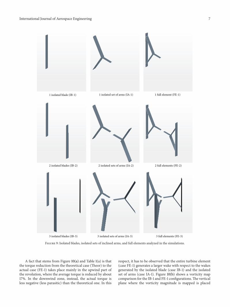
7. Single Element Efficiency
The first part of this study focuses on results obtained for theturbine “single element.” Here a single element is intendedas the single blade with the two arms (see Figure 9, firstrow). The aim of this initial study is to assess the singleelement efficiencywhen it is not influenced by the presence ofother elements. In particular, three different simulations werecarried out:
(i) a simulation concerning one vertical blade alone (IB-1);

6 International Journal of Aerospace Engineering
Figure 7: Real turbine during experiments performed in open field, along with the turbine geometric model used in the simulations.
1.25 1.5 1.75 2 2.25 2.5 2.75 3 3.250.05
0.1
0.15
0.2
0.25
0.3
0.35
0.4
TSR
R = 1.43 C = 0.20 (EXP)R = 1.30 C = 0.20 (NUM)R = 1.30 C = 0.15 (NUM)R = 1.30 C = 0.12 (NUM)
CP
Figure 8: Turbine performance coefficients as a result of experimental (EXP) andnumerical (NUM)data.Numerical analyseswere performedon several geometries (radius 𝑅 and inclined arm chord 𝐶 in meters).
(ii) a simulation concerning one set of inclined armsalone (IA-1);
(iii) a simulation of the full element (FE-1, blade plus thetwo inclined arms).
It has to be observed that the horizontal arms connectingthe inclined arms to the hub have been modeled as well toaccount for their wake effects in the simulations. However,their parasite torque was not considered in the analysespresented in Figure 10(a) and Table 1(a).
Figure 10 shows the instantaneous torque 𝑇 as a functionof the azimuthal position 𝜃 provided by the isolated blade(IB-1), by the isolated couple of inclined arms (IA-1), and bythe full configuration (FE-1).The theoretical curve (THEOR)given by the algebraic sum of IB-1 and IA-1 is also shown.
This latter curve is named “element theoretical torque,” inopposition to the “element actual torque” (FE-1). It turns outthat, as expected, the actual torque average value 𝑇avg,FE islower than the theoretical torque average value 𝑇avg,THEOR. Inparticular, 𝑇avg,FE is about 14% less than 𝑇avg,THEOR. Despitethis fact, the actual average torque is still quite larger than theone provided by the vertical blade alone, 𝑇avg,IB.
Similarly, the average values per revolution of the per-formance coefficient 𝐶
𝑃are compared in Table 1(a) for the
various cases IB-1, IA-1, THEOR, and FE-1. Average valuesin the upwind and downwind zones are also shown in thesame table. The “upwind zone” contribution is the averageof instantaneous 𝐶
𝑃over the range 0∘ ≤ 𝜃 < 180∘. The
“downwind zone” contribution is the average over the range180∘
≤ 𝜃 < 360∘.
International Journal of Aerospace Engineering 7
1 isolated blade (IB-1) 1 isolated set of arms (IA-1) 1 full element (FE-1)
2 isolated blades (IB-2) 2 isolated sets of arms (IA-2) 2 full elements (FE-2)
3 isolated blades (IB-3) 3 isolated sets of arms (IA-3) 3 full elements (FE-3)
Figure 9: Isolated blades, isolated sets of inclined arms, and full elements analyzed in the simulations.
A fact that stems from Figure 10(a) and Table 1(a) is thatthe torque reduction from the theoretical case (Theor) to theactual case (FE-1) takes place mainly in the upwind part ofthe revolution, where the average torque is reduced by about17%. In the downwind zone, instead, the actual torque isless negative (less parasitic) than the theoretical one. In this
respect, it has to be observed that the entire turbine element(case FE-1) generates a larger wake with respect to the wakesgenerated by the isolated blade (case IB-1) and the isolatedset of arms (case IA-1). Figure 10(b) shows a vorticity mapcomparison for the IB-1 and FE-1 configurations.The verticalplane where the vorticity magnitude is mapped is placed

8 International Journal of Aerospace Engineering
0 60 120 180 240 300 360−60
−40
−20
0
20
40
60
80
100
120
Torq
ue (N
m)
Upwind Downwind
IB-1IA-1
TheorFE-1
Instantaneous torque
𝜃 (∘)
(a)
Vort
icity
: mag
nitu
de (/
s)
3.50
2.80
2.10
1.40
0.700
0.000
Vort
icity
: mag
nitu
de (/
s)
3.50
2.80
2.10
1.40
0.700
0.000
(b) (c)
Figure 10: (a) Instantaneous torque generated during one revolution by one isolated blade (IB-1) and one isolated set of arms (IA-1), alongwiththeoretical (arithmetical sum of blade and arms torques, IB-1 plus IA-1) and actual (FE-1) entire element results. (b) Comparison of vorticitymagnitude maps in a plane behind IB-1 (top) and FE-1 (bottom) configurations. (c) Vorticity in a plane behind the FE-1 configuration (freestream coming from lower right). The rotating element is shown in four subsequent positions during one revolution and the dots representthe grid used for the vorticity maps (see Figure 10(b)) and the quantitative evaluation of wake strength (see Table 1(b)).
behind the rotor orthogonally to the free stream velocity(see Figure 10(c)). The high values of the vorticity magnitudein the area immediately behind the “triangle” made by thevertical blade and the two inclined arms (see Figure 10(b),bottom left) give an idea of the stronger wake of the case FE-1over the case IB-1. Average values of the vorticity magnitudeare reported in Table 1(b).
During an entire revolution the rotating element encoun-ters its own wake and one effect of this wake is to reducethe local asymptotic airspeed seen by the blade profiles,decreasing the local incidence angles (see Figure 4). Thepositive pitched blade experiences larger incidence angles inthe downwind zone and a greater reduction of these largeangles has a positive effect on the blade instantaneous torque.

International Journal of Aerospace Engineering 9
0 60 120 180 240 300 360−40
−20
0
20
40
60
80
Torq
ue (N
m)
IB-1IB-2IB-3
Instantaneous torque
𝜃 (∘)
(a)
0 60 120 180 240 300 360−15
−10
−5
0
5
10
15
20
25
30
35
Torq
ue (N
m)
IA-1IA-2IA-3
Instantaneous torque
𝜃 (∘)
(b)
0 60 120 180 240 300 360−40
−20
0
20
40
60
80
100
Torq
ue (N
m)
FE-1FE-2FE-3
𝜃 (∘)
Instantaneous torque
(c)
Figure 11: (a) Instantaneous total torque when a different number of isolated blades are present in the simulation. (b) Instantaneous totaltorque when a different number of isolated set of arms are present in the simulation. (c) Instantaneous total torque when a different numberof full elements are present in the simulation.
On the other hand, in the upwind zone, the local incidenceangles are already small and the reduction introduced by astronger wake (case FE-1) has an evident negative effect.
8. Multiple Elements Efficiency
In successive analyses the turbine element (FE-1, one bladeplus one set of arms) is first doubled, obtaining a two-elementrotor. Then the real turbine composed of three elements
is finally considered. Also in these cases the investigationinvolves first the isolated couple, or triplet, of blades (IB-2 orIB-3), and the isolated couple, or triplet, of arm sets (IA-2 orIA-3). This is aimed at identifying the beneficial sources ofthe full rotor efficiency. These simulations correspond to thecases depicted in the second and third rows of Figure 9.
As shown in Figure 11, increasing the number of singleparts (blades only, or arms only) or elements corresponds toincreasing the number of peaks in the instantaneous torque,

10 International Journal of Aerospace Engineering
0 60 120 180 240 300 360−40
−20
0
20
40
60
80
Torq
ue (N
m)
Upwind Downwind
IB-1IB-2IB-3
𝜃 (∘)
Instantaneous torque per blade
(a)
0 60 120 180 240 300 360−15
−10
−5
0
5
10
15
20
25
30
35
Torq
ue (N
m)
Upwind Downwind
IA-1IA-2IA-3
Instantaneous torque per set of arms
𝜃 (∘)
(b)
0 60 120 180 240 300 360−40
−20
0
20
40
60
80
100
Torq
ue (N
m)
Upwind Downwind
FE-1FE-2FE-3
Instantaneous torque per element
𝜃 (∘)
(c)
Figure 12: (a) Instantaneous torque per blade (generated by a single isolated blade) when a different number of isolated blades are present inthe simulation. (b) Instantaneous torque per set of arms (generated by a single isolated set of arms) when a different number of isolated set ofarms are present in the simulation. (c) Instantaneous torque per element (generated by a single full element) when a different number of fullelements are present in the simulation.
per revolution. From Figures 11(a) and 11(b) it is also seenthat the maximum values generated by three isolated blades(IB-3) and three isolated set of arms (IA-3) is actually greaterthan the peak values generated by one or two blades (IB-1, IB-2) or sets of arms (IA-1, IA-2). As stated above, thisfact is due (beside the merely contribution of more thanone part) to the greater wake generated by the presence ofmultiple parts, which effectively increases the performances
in the downwind zone. As stated in Table 2, the averageperformance coefficient for both isolated blades and set ofarms grows with the number of elements involved.
However, when it comes to the full elements, passing toFE-2 and FE-3, the curves of Figure 11(c) show thatmaximuminstantaneous torque is actually smaller than the one gener-ated by only one element FE-1. This is due to a stronger wakethat compromises the performance of each single element in

International Journal of Aerospace Engineering 11
Table 1: (a) Average 𝐶𝑃
generated during one revolution by oneisolated blade (IB-1) and one isolated set of arms (IA-1), along withtheoretical (IB-1 plus IA-1) and actual full element (FE-1) results. (b)Average vorticity magnitude in a vertical plane behind the turbine,orthogonal to the free stream velocity (see Figure 10(c)).
(a)
CaseAverage 𝐶
𝑃
Upwindzone
Downwindzone
Fullrevolution
IB-1 0.220 −0.024 0.098IA-1 0.096 −0.021 0.038THEOR 0.316 −0.045 0.136FE-1 0.261 −0.027 0.117 (−14%)
(b)
IB-1 IA-1 FE-10.562 1/s 0.445 1/s 0.913 1/s
Table 2: Average performance coefficient on one revolution for allthe considered cases.
Case Average 𝐶𝑃
% differencecompared to the∗-1 case
IB-1 0.098IB-2 0.214 +118%IB-3 0.369 +276%IA-1 0.038IA-2 0.081 +113%IA-3 0.148 +289%FE-1 0.117FE-2 0.258 +120%FE-3 0.259 +121%
both the upwind and downwind zones. With respect to thecase FE-2, the wakes of each rotating element in case FE-3 are separated (azimuthally) by 120∘ instead of 180∘. In thedownwind zone each element encounters a wake three timesper revolution instead of two times (FE-2) or one time (FE-1).
As stated in Table 2, the average performance coefficientreaches a maximum with two elements (FE-2), and thenremains substantially unchanged even if a third element isadded (FE-3).
To further enhance the understanding of the previousresults, the behavior of a single part (or element) whenother parts (or elements) are present is shown in Figure 12and Table 3. Their efficiencies will be compared to the onesobtained when they operate alone. In the next plots, theinstantaneous torque per single part (or per element) will beshown when one, two or three parts (or elements) are presentin the simulation.
Figure 12(a) shows the instantaneous torque per bladein cases IB-1, IB-2, IB-3. Similarly, Figure 12(b) shows thetorque per set of inclined arms in cases IA-1, IA-2 and IA-3.Finally, Figure 12(c) shows the torque per full element in cases
Table 3: Average performance coefficient per element on onerevolution, when different numbers of elements are present in thesimulation.
CaseAverage 𝐶
𝑃
per elementUpwindzone
Downwindzone
Fullrevolution
FE-1 0.261 −0.027 0.117FE-2 0.215 0.042 0.129 (+10%)FE-3 0.152 0.020 0.086 (−26%)
FE-1, FE-2, FE-3; the latter is the actual three-element rotorconfiguration.
The average values on one revolution of the performancecoefficients are shown in Table 3. Partial average values, in theupwind and downwind zones, are also reported.
It is clearly seen that a rotor with two elements (FE-2)has an average performance coefficient per element higherthan the single element case (FE-1). Passing from case FE-1 tocase FE-2, larger wake effects tend to decrease the per elementefficiency in the upwind zone; at the same time the efficiencyis increased significantly in the downwind zone. The result isthe greatest average value per element achieved by 𝐶
𝑃(+10%
in case FE-2 compared to the case FE-1).Nonetheless, when the number of elements is increased
from two (FE-2) to three (FE-3) the even larger wake effectsgenerated by the presence of all the turbine elements tend todecrease the overall per element efficiency in both the upwindand downwind zones. The result is the worst average value of𝐶𝑃(−26% in case FE-3 in comparison to the case FE-1).Wakes of all the different configurations of Figure 9 are
depicted in the set of Figure 13(a) in terms of scalar fieldsof the 𝑋-velocity component (same direction as 𝑈
∞) taken
at the mid-hub height. Example of velocity vector fields inplanes’ orthogonal to the turbine axis is reported in Fig-ure 13(b). Examples of streamlines and vorticity magnitudemaps are shown in Figure 13(c).
9. Results with DifferentTurbine Radii and Arm Chords
A final investigation is presented here that emphasizes therole of two geometrical parameters: the turbine radius andthe arm chord length.
Figure 14(a) shows that an optimal radius exists thatmaximizes the peak of 𝐶
𝑃with TSR when all the geometrical
and aerodynamic parameters are fixed, for a given windvelocity. Figure 14(b) shows that lesser chord lengths of theinclined arms bring performance improvements (at higherTSRs). This is clearly due to the reduction of parasite drag.
One of the aims of the paper is to bring up the aboveconcepts, in particular by decreasing the inclined arm chord;starting from a baseline case, one obtains an efficiencyimprovement. The assessment of efficiency trends with vary-ing inclined arm chords and blade pitching angles is the scopeof a future article.

12 International Journal of Aerospace Engineering
IB-1 IB-2 IB-3
IA-1 IA-2 IA-3
FE-1 FE-2 FE-3
(a)
(b)
0.000
Y X
Velo
city
: mag
nitu
de (m
/s)
4.000
4.800
5.600
6.400
7.200
8.000Y
Y
Z
X
X
Vort
icity
: mag
nitu
de (/
s)100.000
80.000
60.000
40.000
20.000Z
25.000
YZ
Y
X
X
20.000
15.000
10.000
5.000
0.000
Vort
icity
: mag
nitu
de (/
s)
(c)
Figure 13: (a) Scalar fields of𝑋-velocity component, which has the same direction of the asymptotic wind velocity (wind blowing from left toright), taken at hub height. First row shows simulation results for one or multiple blades. Second row shows results for one or multiple arms.Third row shows results for one or multiple turbine elements. The blockage effect of the turbine is clearly seen, especially in the downwindzone, being enhanced as the number of elements grown. The local presence of reverse flow is also visible. (b) Velocity vector fields in a planeorthogonal to the turbine axis. (c) Streamlines (top) and vorticity magnitude maps in planes orthogonal to the turbine axis (middle) and inplanes orthogonal to the free stream velocity, in the downwind zone (bottom).

International Journal of Aerospace Engineering 13
1.5 2 2.5 3 3.50
0.05
0.1
0.15
0.2
0.25
0.3
0.35
TSR
Performance coefficient
CP
R = 1.3mR = 1.6mR = 1.9m
cA = 0.20m
(a)
1.5 2 2.5 3 3.50
0.05
0.1
0.15
0.2
0.25
0.3
0.35
TSR
Performance coefficient
CP
cA = 0.20mcA = 0.15mcA = 0.12m
R = 3.0m
(b)
Figure 14: (a) Performance coefficient against tip speed ratio for different turbine radii (FE-3). (b) Performance coefficient against tip speedratio for different arm chord lengths (FE-3).
10. Conclusions
Performances and flow fields for a wind turbine with uncon-ventional arms geometry were numerically computed solvingthe three-dimensional RANS equations with SST K-Omegaturbulence model. Initially, results for a single blade-plus-arms element were presented, and it has been shown thatthe presence of inclined/profiled arms actually increases theaverage value (per revolution) of performance coefficient.Also, the larger wake effects generated by the presence ofthe arms seem to increase the performance of the positive-pitched blade in the downwind zone by reducing its localincidence angle. These positive results are further enhancedas the number of turbine elements is brought to two. Whenthe number of turbine elements is then set to the originalvalue of three, the very large blockage effect on the incomingwind flow is clearly felt on the turbine performances.
The number of blades is just one of the many parame-ters that can be investigated. Results can change greatly ifparameters such as turbine radius, arm chord, and blade pitchare changed. Arm chord, especially, is a fundamental variableas a small reduction of this parameter could lead to minorblockage effect on the flow while still guaranteeing a positivetorque during the revolution.
Conflict of Interests
The authors declare that there is no conflict of interestsregarding the publication of this paper.
References
[1] I. Paraschivoiu, Wind Turbine Design: With Emphasis onDarrieus Concept, Polytechnic International Press, Montreal,Canada, 2002.
[2] C. A. Consul, R. H. J. Willden, E. Ferrer, and M. D. McCulloch,“Influence of solidity on the performance of a cross-flowturbine,” in Proceedings of the 8th European Wave and TidalEnergy Conference (EWTEC ’09), Uppsala, Sweden, 2009.
[3] K. Hamada, T. Smith, N. Durrani, N. Qin, and R. Howell,“Unsteady flow simulation and dynamic stall around verticalaxis wind turbine blades,” in Proceedings of the 46th AIAAAerospace Sciences Meeting and Exhibit, AIAA 2008-1319, Reno,Nevada, January 2008.
[4] R. Howell, N. Qin, J. Edwards, and N. Durrani, “Wind tunneland numerical study of a small vertical axis wind turbine,”Renewable Energy, vol. 35, no. 2, pp. 412–422, 2010.
[5] C. J. Simao Ferreira, A. van Zuijlen, H. Bijl, G. van Bussel, andG. van Kuik, “Simulating dynamic stall in a two-dimensionalvertical-axis wind turbine: verification and validation withparticle image velocimetry data,”Wind Energy, vol. 13, no. 1, pp.1–17, 2010.
[6] P. R. Spalart and S. R. Allmaras, “A one-equation turbulencemodel for aerodynamic flows,” in Proceedings of the 30thAerospace SciencesMeeting and Exhibit, AIAA, Reno, Nev, USA,1992.
[7] F. R. Menter, “Zonal two equation k-𝜔 turbulence models foraerodynamic flows,” AIAA Paper 93-2906, 1993.
[8] M. R. Castelli, G. Simioni, and E. Benini, Numerical Analysisof the Influence of Airfoil Asymmetry on VAWT Performance,Engineering and Technology 61, World Academy of Science,2012.

14 International Journal of Aerospace Engineering
[9] M. R. Castelli and E. Benini, “Effect of blade inclination angleon a darrieuswind turbine,” Journal of Turbomachinery, vol. 134,no. 3, Article ID 031016, 10 pages, 2011.
[10] M. Raciti Castelli, S. de Betta, and E. Benini, “Effect of bladenumber on a straight-bladed vertical-axis Darreius wind tur-bine,” World Academy of Science, Engineering and Technology,vol. 64, pp. 206–212, 2012.
[11] M. Raciti Castelli, A. Englaro, and E. Benini, “The Darrieuswind turbine: proposal for a newperformance predictionmodelbased on CFD,” Energy, vol. 36, no. 8, pp. 4919–4934, 2011.
[12] E. Amet, T. Maıtre, C. Pellone, and J.-L. Achard, “2D numericalsimulations of blade-vortex interaction in a darrieus turbine,”Journal of Fluids Engineering, vol. 131, no. 11, Article ID 111103,15 pages, 2009.
[13] I. S. Hwang, Y. H. Lee, and S. J. Kim, “Optimization of cycloidalwater turbine and the performance improvement by individualblade control,” Applied Energy, vol. 86, no. 9, pp. 1532–1540,2009.
[14] D. P. Coiro, G. Troise, F. Scherillo, A. de Marco, and U.Maisto, “Experimental tests of GEM-Ocean’s kite, an innovativepatented submerged system for marine current energy produc-tion,” in Proceedings of the 3rd International Conference onCleanElectrical Power: Renewable Energy Resources Impact (ICCEP’11), pp. 223–230, Capri, Italy, June 2011.
[15] D. P. Coiro, F. Nicolosi, A. deMarco, S. Melone, and F.Montella,“Dynamic behavior of novel vertical axis tidal current turbine:numerical and experimental investigations,” in Proceedings ofthe 15th International Offshore and Polar Engineering Conference(ISOPE ’05), Seoul, Republic of Korea, June 2005.
[16] D. P. Coiro, F. Nicolosi, A. deMarco, S. Melone, and F.Montella,“Flow curvature effects on dynamic behaviour of a novel verticalaxis tidal current turbine: numerical and experimental analysis,”in Proceedings of the ASME 24th International Conference onOffshoreMechanics andArctic Engineering (OMAE ’05), pp. 601–609, Halkidiki, Greece, June 2005.
[17] R. Courant, K. Friedrichs, and H. Lewy, “Uber die partiellendifferenzengleichungen der mathematischen physik,” Mathe-matische Annalen, vol. 100, no. 1, pp. 32–74, 1928.
[18] International Electrotechnical Commission, IEC InternationalStandard 61400-1, 3rd edition, 2007.
[19] L. Merola, “The S.Co.P.E. Project,” 2006.

International Journal of
AerospaceEngineeringHindawi Publishing Corporationhttp://www.hindawi.com Volume 2014
RoboticsJournal of
Hindawi Publishing Corporationhttp://www.hindawi.com Volume 2014
Hindawi Publishing Corporationhttp://www.hindawi.com Volume 2014
Active and Passive Electronic Components
Control Scienceand Engineering
Journal of
Hindawi Publishing Corporationhttp://www.hindawi.com Volume 2014
International Journal of
RotatingMachinery
Hindawi Publishing Corporationhttp://www.hindawi.com Volume 2014
Hindawi Publishing Corporation http://www.hindawi.com
Journal ofEngineeringVolume 2014
Submit your manuscripts athttp://www.hindawi.com
VLSI Design
Hindawi Publishing Corporationhttp://www.hindawi.com Volume 2014
Hindawi Publishing Corporationhttp://www.hindawi.com Volume 2014
Shock and Vibration
Hindawi Publishing Corporationhttp://www.hindawi.com Volume 2014
Civil EngineeringAdvances in
Acoustics and VibrationAdvances in
Hindawi Publishing Corporationhttp://www.hindawi.com Volume 2014
Hindawi Publishing Corporationhttp://www.hindawi.com Volume 2014
Electrical and Computer Engineering
Journal of
Advances inOptoElectronics
Hindawi Publishing Corporation http://www.hindawi.com
Volume 2014
The Scientific World JournalHindawi Publishing Corporation http://www.hindawi.com Volume 2014
SensorsJournal of
Hindawi Publishing Corporationhttp://www.hindawi.com Volume 2014
Modelling & Simulation in EngineeringHindawi Publishing Corporation http://www.hindawi.com Volume 2014
Hindawi Publishing Corporationhttp://www.hindawi.com Volume 2014
Chemical EngineeringInternational Journal of Antennas and
Propagation
International Journal of
Hindawi Publishing Corporationhttp://www.hindawi.com Volume 2014
Hindawi Publishing Corporationhttp://www.hindawi.com Volume 2014
Navigation and Observation
International Journal of
Hindawi Publishing Corporationhttp://www.hindawi.com Volume 2014
DistributedSensor Networks
International Journal of